1
Selection
and Operation
A Shure Educational Publication
Selection
and
Operation
of
Wireless
Microphone
Systems
Wireless
Microphone Systems
By Tim Vear
2ND EDITION
A B L E
O F
C
O N T E N T S
Introduction . . . . . . . . . . . . . . . . . . . . . . . . 4
PART ONE
WIRELESS MICROPHONE SYSTEMS:
HOW THEY WORK
CHAPTER 1
BASIC RADIO PRINCIPLES . . . . . . . . . . 5
Radio Wave Transmission . . . . . . . . . . . . . 5
Radio Wave Modulation . . . . . . . . . . . . . . 7
BASIC RADIO SYSTEMS . . . . . . . . . . . . 8
System Description . . . . . . . . . . . . . . . . . . 8
Input Sources . . . . . . . . . . . . . . . . . . . . . . 8
Transmitter: General Description . . . . . . . . 9
Transmitter: Audio Circuitry . . . . . . . . . . . 10
Transmitter: Radio Circuitry . . . . . . . . . . . 11
Receiver: General Description . . . . . . . . . 12
Receiver: Radio Circuitry . . . . . . . . . . . . . 12
Receiver: Audio Circuitry . . . . . . . . . . . . . 14
Receiver: Squelch . . . . . . . . . . . . . . . . . . 14
Receiver: Antenna Configuration . . . . . . . 15
Multipath . . . . . . . . . . . . . . . . . . . . . . . . . 15
New! Receiver: Diversity Techniques . . 16
New! Antennas . . . . . . . . . . . . . . . . . . . 18
New! Antenna Cable . . . . . . . . . . . . . . . 20
Antenna Distribution . . . . . . . . . . . . . . . . . 20
WIRELESS SYSTEM OPERATION . . . . . 22
New! Frequency Bands for
Wireless Systems . . . . . . . . . . . . . . . . . . . 22
VHF . . . . . . . . . . . . . . . . . . . . . . . . . . . . . 22
UHF . . . . . . . . . . . . . . . . . . . . . . . . . . . . . 23
New! Frequency Selection . . . . . . . . . . . 24
System Compatibility . . . . . . . . . . . . . . . . 25
Operating Frequency Interactions:
Intermodulation . . . . . . . . . . . . . . . . . . . . 25
Internal Frequency interactions: LO, IF,
Crystal Multipliers . . . . . . . . . . . . . . . . . . . 26
Non-System Radio Interference . . . . . . . . 28
New! Broadcast Television . . . . . . . . . . . 28
Broadcast Radio . . . . . . . . . . . . . . . . . . . . 31
Other Radio Services . . . . . . . . . . . . . . . . 31
Non-Broadcast Sources . . . . . . . . . . . . . . 31
Spread Spectrum Transmission . . . . . . . . 32
Range of Wireless Microphone Systems . 33
New! Digital Wireless Systems . . . . . . . 34
New! Operation of Wireless Systems
Outside of the U.S. . . . . . . . . . . . . . . . . . 35
PART TWO
WIRELESS MICROPHONE SYSTEMS:
HOW TO MAKE THEM WORK
of Wireless Microphone Systems
CHAPTER 2
CHAPTER 3
Selection and Operation
T
CHAPTER 4
WIRELESS SYSTEM
SELECTION AND SETUP . . . . . . . . . . . 36
New! System Selection . . . . . . . . . . . . . 36
New! Crystal Controlled vs.
Frequency Synthesis . . . . . . . . . . . . . . . . 37
System Setup: Transmitter . . . . . . . . . . . . 37
System Setup: Receivers . . . . . . . . . . . . . 39
System Setup: Receiver Antennas . . . . . . 42
System Setup: Batteries . . . . . . . . . . . . . . 43
System Checkout and Operation . . . . . . . 43
Troubleshooting
Wireless Microphone Systems . . . . . . . . . 44
Troubleshooting Guide . . . . . . . . . . . . . . 45
CHAPTER 5
APPLICATION NOTES . . . . . . . . . . . . . 46
Presenters . . . . . . . . . . . . . . . . . . . . . . . . 46
Musical Instruments . . . . . . . . . . . . . . . . . 46
Vocalists . . . . . . . . . . . . . . . . . . . . . . . . . . 47
Aerobic/Dance Instruction . . . . . . . . . . . . 48
Theater . . . . . . . . . . . . . . . . . . . . . . . . . . . 48
Worship . . . . . . . . . . . . . . . . . . . . . . . . . . 49
Bingo . . . . . . . . . . . . . . . . . . . . . . . . . . . . 49
Film/Videography . . . . . . . . . . . . . . . . . . .50
Broadcast . . . . . . . . . . . . . . . . . . . . . . . . . 50
New! Point-to-Point Wireless . . . . . . . . . 51
Large Room/Multi-Room Applications . . . 51
Conclusion . . . . . . . . . . . . . . . . . . . . . . . . 54
REFERENCE INFORMATION
Appendix A: Calculation of
Intermodulation Products . . . . . . . . . . . . 55
Appendix B: U.S. Television Channels . . . 57
Glossary of Terms and Specifications . . . 58
Included Illustrations . . . . . . . . . . . . . . . . 61
Suggested Reading & Biography . . . . . . 62
3
of Wireless Microphone Systems
Selection and Operation
I
N T R O D U C T I O N
The many uses of wireless microphone systems can span applications
from live entertainment to earth-orbit communications. It can include
devices from a single "Mr. Microphone" to a 60 channel theme park system.
It can evoke visions of freedom in prospective users and memories of
ancient disaster in veteran sound engineers. In all its forms, wireless has
become a fact of life for people who design and use audio systems. With
increased use of wireless microphone systems has come the need for
increased quantity and quality of information on the topic.
The scope of this guide is limited to wireless microphone systems used in
audio applications. The reader is presumed to be somewhat familiar with
basic audio. However, since wireless microphone systems depend upon
certain general principles of radio, some information on basic radio is
included. While there are similarities between sound transmission and radio
transmission, many of the characteristics of radio systems are neither
analogous to audio systems nor intuitive. Still, though perhaps new, the key
ideas are fairly straightforward.
The purpose of this guide is to provide the interested reader with adequate
information to select suitable wireless equipment for a given application
and to use that equipment successfully. In addition, it is hoped that the
fundamentals presented here will equip regular users of wireless with a
framework to assist in their further understanding of this evolving technology.
This guide is presented in two parts: how wireless microphone systems
work and how to make wireless microphone systems work. The first part
is a technical introduction to the basic principles of radio and to the
characteristics of wireless transmitters and receivers. The second part
discusses the practical selection and operation of wireless microphone
systems for general and specific applications. The two parts are intended
to be self-contained. The first part should be of interest to those who
specify or integrate professional wireless equipment while the second
part should be of use to anyone who regularly works with wireless
microphone systems.
4
Part One: Wireless Microphone Systems: How They Work
H A P T E R
1
Basic Radio Principles
RADIO WAVE TRANSMISSION
of Wireless Microphone Systems
Radio refers to a class of time-varying electromagnetic
fields created by varying voltages and/or currents in
certain physical sources. These sources may be "artificial,"
such as electrical power and electronic circuits, or
"natural," such as the atmosphere (lightning) and stars
(sunspots). The electromagnetic field variations radiate
outward from the source forming a pattern called a radio
wave. Thus, a radio wave is a series of electromagnetic
field variations travelling through space. Although,
technically, any varying source of voltage or current
produces a varying field near the source, here the term
"radio wave" describes field variations that propagate a
significant distance away from the source.
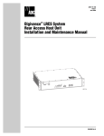
A sound wave has only a single "field" component (air
pressure). Variations in this component create a pattern of
air pressure changes along the direction the sound wave
travels but otherwise have no particular orientation. In
contrast, a radio wave includes both an electric field
component and a magnetic field component. The
variations in these components have the same relative
pattern along the direction the radio wave travels but they
are oriented at a 90 degree angle to each other as
illustrated in Figure 1-1. In particular, it is the orientation of
the electric field component which determines the angle of
"polarization" of the radio wave. This becomes especially
important in the design and operation of antennas.
frequencies in the range just below visible light, which are
perceived as heat (infrared radiation). The overall radio
spectrum includes both natural and artificial sources as
indicated by Figure 1-2.
The amplitude of a radio wave is the magnitude of the
field variations. It is the characteristic that determines the
"strength" of the radio wave. Specifically, it is defined to be
the amplitude of the electric field variation. It is measured
in volts per unit length and ranges from nanovolts/meter
(nV/m) to kilovolts/meter (KV/m), where nV refers to one
billionth of a volt and KV refers to one thousand volts.
The minimum level required for pickup by a typical radio
receiver is only a few tens of microvolts (uV, a millionth of a
volt) but much higher levels can be found near transmitters
and other sources. The wide range of radio wave
amplitudes that may be encountered in typical
applications requires great care in the design and use of
wireless microphone systems, particularly receivers.
Selection and Operation
C
Figure 1-2: frequency vs. wavelength
y
x
Magnetic Field
Electric Field
Figure 1-1: radio wave
Like sound waves, a radio wave can be described by
its frequency and its amplitude. The frequency of a radio
wave is the time rate of the field variations measured in
Hertz (Hz), where 1 Hz equals 1 cycle-per-second. The
radio spectrum, or range of frequencies, extends from a
few Hertz through the Kilohertz (KHz) and Megahertz
(MHz) ranges, to beyond the Gigahertz (GHz) range. The
suffixes KHz, MHz, and GHz refer to thousands, millions,
and billions of cycles-per-second respectively. As far as is
presently known, humans are directly sensitive to radio
waves only at frequencies in the range of a few million
GHz, which are perceived as visible light, and at those
Another characteristic of waves, related to frequency,
is wavelength. The wavelength is the physical distance
between the start of one cycle and the start of the next
cycle as the wave moves through space. Wavelength is
related to frequency by the speed at which the wave
travels through a given medium. This relationship is
expressed in the wave equation, which states that the
speed of the wave is always equal to the product of the
frequency times the wavelength. The wave equation
applies to any physical wave phenomenon such as radio
waves, sound waves, seismic waves, etc. (See Figure 1-3.)
Figure 1-3: the wave equation
5
of Wireless Microphone Systems
Selection and Operation
C
H A P T E R
1
Basic Radio Principles
The speed of radio waves (through a
vacuum) is equal to approximately 3 x 10⁸
meter/second, or about 186,000 miles/
second. This is also known as the "speed of
light," since light is just one part of the radio
spectrum. The wave equation states that the
frequency of a radio wave, multiplied by its
wavelength always equals the speed of light.
Thus, the higher the radio frequency, the
shorter the wavelength, and the lower the
frequency, the longer the wavelength. Typical
wavelengths for certain radio frequencies are
given in Figure 1-3. Wavelength also has important
consequences for the design and use of wireless
microphone systems, particularly for antennas.
Unlike sound, radio waves do not require a physical
substance (such as air) for transmission. In fact, they
"propagate" or travel most efficiently through the vacuum of
space. However, the speed of radio waves is somewhat
slower when travelling through a medium other than
vacuum. For example, visible light travels more slowly
through glass than through air. This effect accounts for the
"refraction" or bending of light by a lens. Radio waves can
also be affected by the size and composition of objects in
their path. In particular, they can be reflected by metal objects
if the size of the object is comparable to or greater than the
wavelength of the radio wave. Large surfaces can reflect
both low frequency (long wavelength) and high frequency
(short wavelength) waves, but small surfaces can reflect
only high frequency (short) radio waves. (See Figure 1-5.)
Interestingly, a reflecting metal object can be porous,
that is, it can have holes or spaces in it. As long as the
holes are much smaller than the wavelength, the metal
surface will behave as if it were solid. This means that
screens, grids, bars, or other metal arrays can reflect radio
waves whose wavelength is greater than the space
between the array elements and less than the overall array
size. If the space between elements is larger than the
wavelength, the radio waves will pass through the array.
For example, the metal grid on the glass door of a
microwave oven reflects microwaves back into the oven
but allows light waves to pass through so that the inside is
visible. This is because microwaves have a wavelength of
6
at least one centimeter while visible light has a wavelength
of only one-millionth of a meter. (See Figure 1-4)
Even metal objects that are somewhat smaller than the
wavelength are able to bend or "diffract" radio waves.
Generally, the size, location, and quantity of metal in the
vicinity of radio waves will have significant effect on their
behavior. Non-metallic substances (including air) do not
reflect radio waves but are not completely transparent either.
To some degree, they generally "attenuate" or cause a loss
in the strength of radio waves that pass through them. The
amount of attenuation or loss is a function of the thickness
and composition of the material and also a function of the
radio wavelength. In practice, dense materials produce
more losses than lighter materials and long radio waves (low
frequencies) can propagate greater distances through
"lossy" materials than short radio waves (high frequencies).
The human body causes significant losses to short radio
waves passing through it.
An object that is large enough to reflect radio
waves or dense enough to attenuate them can
create a "shadow" in the path of the waves which
can greatly hamper reception of radio in the area
beyond the object.
A final parallel between sound waves and
radio waves lies in the nature of the overall radio
wave pattern or "field" produced by various
sources at a given location. If reflections are
present (which is nearly always the case
indoors), the radio field will include both direct
waves (those that travel by the shortest path
from the source to the location) and indirect waves (those
that are reflected). Radio waves, like sound waves, become
weaker as they travel away from their source, at a rate
governed by the inverse-square law: at twice the distance,
the strength is decreased by a factor of four (the square of
two). The strength of radio waves that arrive at a given
location, by direct or indirect paths, is equal to the strength
of the original source(s) minus the amount of loss due to
distance (inverse square loss), loss due to material
attenuation, and loss due to reflections.
After many reflections radio waves become weaker and
essentially non-directional. They ultimately contribute to
H A P T E R
1
Basic Radio Principles
RADIO WAVE MODULATION
This discussion of radio transmission has so far dealt
only with the basic radio wave. It is also necessary to
consider how information is carried by these waves. Audio
"information" is transmitted by sound waves which consist
of air pressure variations over a large range of amplitudes
and frequencies. This combination of varying amplitudes
and varying frequencies creates a highly complex sound
field. These varying pressure waves are able to be
processed directly by our auditory systems to perceive
speech, music, and other intelligible sounds (information).
Radio "information" is generally transmitted using only
one frequency. This single electromagnetic wave is varied
in amplitude, frequency, or some other characteristic (such
as phase) and for most radio transmissions neither the wave
nor its variation can be detected or processed directly by
human senses. In fact, the wave itself is not the
information but rather the "carrier" of the information. The
information is actually contained in the amplitude variation or
frequency variation, for example. When a radio wave
contains information it is called a radio "signal."
The
general term for this information-carrying variation of radio
waves is "modulation." If the amplitude of the wave is varied
the technique is called Amplitude Modulation or AM. If the
frequency is varied, it is called Frequency Modulation or FM.
The amount of information that can be carried in a radio
signal depends on the type of modulation and the level of
modulation that can be applied to the basic radio wave. It also
depends on the frequency of the basic radio wave. These
factors are limited by physics to some extent, but are also
limited by regulatory agencies such as the FCC. For AM
signals, the radio wave has a single (constant) frequency of
some basic amplitude (determined by the transmitter power).
This amplitude is varied up and down (modulated) by the
audio signal to create the corresponding radio signal. The rate
of modulation is equal to the frequency of the audio signal and
the amount of modulation is proportional to the amplitude
(loudness) of the audio signal. The maximum (legal) amount
Figure 1-6: amplitude modulation (AM)
of amplitude modulation allows an audio signal of only limited
frequency response (about 50-9000 Hz) and limited dynamic
range (about 50 dB). (See Figure 1-6.)
For FM signals, the radio wave has a constant
amplitude (again determined by transmitter power) and
a basic frequency. The basic radio frequency is varied up and
down (modulated) by the audio signal to create the corresponding radio signal. This frequency modulation is called
"deviation" since it causes the carrier to deviate up and down
from its basic or unmodulated frequency. (See Figure 1-7.)
of Wireless Microphone Systems
ambient radio "noise," that is, general radio energy
produced by many natural and man-made sources across
a wide range of frequencies. The strength of ambient radio
noise is relatively constant in a given area, that is, it does not
diminish with distance. The total radio field at a given location consists of direct waves, indirect waves and radio noise.
Radio noise is nearly always considered to be
undesirable. The direct and indirect waves may come from
both the desired source (the intended transmission) and
undesirable sources (other transmissions and general radio
energy emitters). Successful radio reception depends on a
favorable level of the desired transmission compared to the
level of undesirable transmissions and noise.
Selection and Operation
C
Figure 1-7: frequency modulation (FM)
The amount of deviation is a function of the amplitude
of the audio signal and is usually measured in kilohertz
(KHz). Typical values of deviation in wireless microphone
systems range from about 12KHz to 45KHz depending on
the operating frequency band. The maximum (legal)
amount of deviation allows an audio signal of greater
frequency response (about 50-15,000 Hz) and greater
dynamic range (more than 90 dB) than does AM.
Although the details of wireless microphone transmitters
and receivers will be covered in the next section, it should be
noted here that all of the systems discussed in this presentation use the FM technique. The reasons for this are the same
as are apparent in commercial broadcast systems. More
"information" can be sent in the typical FM signal, allowing
higher fidelity audio signals to be transmitted. In addition, FM
receivers are inherently less sensitive to many common
sources of radio noise, such as lightning and electrical power
equipment. These sources are characterized by a high level
of AM-type noise which is rejected by FM systems.
7
of Wireless Microphone Systems
Selection and Operation
8
C
H A P T E R
2
Basic Radio Systems
The output of the receiver is typically monitored through
headphones or loudspeakers. It may feed a portable
The function of a radio or "wireless" system is to send
audio or video recorder. This is the configuration of
information in the form of a radio signal. In this presentation,
wireless systems for in-ear-monitors, (IEMs) interruptible
the information is assumed to be an audio signal, but of
foldback systems (IFB), assistive listening, simultaneous
course video, data, or control signals can all be sent via
translation, and various instructional uses. It is also, of
radio waves. In each case, the information must be
course, the configuration of commercial radio and
converted to a radio signal, transmitted, received, and
television broadcast systems when the receiver is mobile
converted back to its original form. The initial conversion
such as a personal radio or a car radio.
consists of using the original information to create a radio
The third configuration consists of both a portable
signal by "modulating" a basic radio wave. In the final
transmitter and a portable receiver. The users of both
conversion, a complementary technique is used to
components are free to move about. Again, the input
"demodulate" the radio signal to recover the original
source is usually a microphone and the output is often a
information.
headphone. This is the configuration of "wireless
A wireless microphone system consists generally of
intercom" systems, though each user in a typical setup
three main components: an input source, a transmitter,
has both a transmitter and a receiver for two-way
and a receiver.
communication.
(See Figure 2-1.) The
Another application
input source provides
of this configuration
an audio signal to the
is for transmission
transmitter. The
of audio from
transmitter converts the
a wireless
audio signal to a radio
microphone to a
signal and "broadcasts"
portable camera/
or transmits it to the
recorder in
surrounding area.
broadcast, film, and
Figure 2-1: general radio system diagram
The receiver "picks
videography.
up" or receives the radio signal and converts it back into an
The fourth configuration comprises a transmitter
audiosignal. Additional system components include
and a receiver that are each stationary. Such setups
antennas and, possibly, antenna cables and distribution
are often referred to as "point-to-point" wireless
systems. The processes and the basic components are
systems. The typical input would be a playback source
functionally similar to commercial radio and television and
or mixer while the output might be to a sound system
other forms of radio communications. What differs is the
or to a broadcast facility. Examples of this setup are
component scale and the physical system configurations.
wireless audio feeds to multiple amplifier/loudspeaker
There are four basic configurations of wireless
arrays for temporary distributed sound systems, radio
microphone systems, related to the mobility of the
remote-to-studio links and of course commercial and
transmitter and receiver components, as required for
non-commercial broadcasts from fixed transmitters to
different applications. The first configuration involves a
fixed receivers.
portable transmitter and a stationary receiver. The
transmitter is usually carried by the user, who is free to
INPUT SOURCES
move about, while the receiver is located in a fixed
position. The input source in this setup is normally a
The input source is any device that provides a suitable
microphone or an electronic musical instrument. The
audio signal to the transmitter. "Suitable audio signal"
receiver output is typically sent to a sound system,
means an electrical signal within a certain frequency range
recording equipment, or a broadcast system. This is the
(audio), voltage range (microphone level or line level), and
configuration of the standard "wireless microphone" and is
impedance range (low or high) that can be handled by the
the arrangement most widely used in entertainment,
transmitter. Though this places some limits on input
public address, and broadcast applications.
sources, it will be seen that almost any type of audio
The second configuration employs a stationary
signal can be used with one system or another.
transmitter and a portable receiver. In this case, the user
The most common input source is a microphone,
carries the receiver, while the transmitter is fixed. The input
which may take any one of a variety of forms: handheld,
source to the transmitter for these setups is usually a
lavaliere, headworn, instrument-mounted, etc. The audio
sound system, playback system, or other installed source.
signal provided by this source is audio frequency,
SYSTEM DESCRIPTION
H A P T E R
2
Basic Radio Systems
to clothing or belt, or may be placed in a pocket or pouch.
In theater and some other applications they may be
concealed underneath clothing. Input is made from the
source to the bodypack via a cable, which may be
permanently attached or detachable at a connector. This
connector may allow a variety of input sources to be used
with one transmitter.
Bodypack transmitter controls include at least a power
switch and often a separate mute switch, allowing the
audio input to be silenced without interrupting the radio
signal. Other controls may include gain adjustment,
attenuators, limiters and, in tuneable systems, a provision
for frequency selection. Indicators (usually LED’s) for
power-on and battery condition are desirable, while
tuneable units sometimes include digital readouts of
frequency. A few transmitters are equipped with audio
"peak" indicators. Finally, the antenna for a bodypack
transmitter may be in the form of a flexible attached wire, a
short "rubber ducky" type, or the input source cable itself,
such as a guitar cable or lavaliere microphone cable.
Handheld transmitters, as the name implies, consist of
a handheld vocal microphone element integrated with a
transmitter built into the handle. The complete package
appears only slightly larger than a wired handheld
microphone. It may be carried in the hand or mounted on
a microphone stand using an appropriate swivel adapter.
Input from the microphone element is direct via an internal
connector or wires. Some models have removable or
interchangeable microphone elements.
of Wireless Microphone Systems
microphone level, and usually low impedance. Since the
"wireless" part of the wireless microphone only serves to
replace the cable, ideally, the characteristics and
performance of a particular microphone should not
change when used as part of a wireless microphone system.
Therefore, the selection of microphone type for a
wireless microphone system should be made following
the same guidelines as for wired microphones. The usual
choices of operating principle (dynamic/condenser),
frequency response (flat/shaped), directionality
(omnidirectional/unidirectional),
electrical
output
(balanced/unbalanced, low or high impedance), and
physical design (size, shape, mounting, etc.) must still be
made correctly. Problems that result from improper
microphone choice will only be aggravated in a wireless
application.
Another widely encountered input source is an
electronic musical instrument, such as an electric guitar,
electric bass, or portable electronic keyboard. The signal
from these sources is again audio frequency, microphone
or line level, and usually high impedance. The potentially
higher signal levels and high impedances can affect
transmitter choice and operation.
Finally, general audio signal sources such as mixer
outputs, cassette or CD players, etc. may be considered.
These exhibit a wide range of levels and impedances.
However, as long as these characteristics are within the
input capabilities of the transmitter they may be
successfully used.
Selection and Operation
C
TRANSMITTER:
GENERAL DESCRIPTION
Transmitters can be either fixed or portable as mentioned earlier. Regardless of type, transmitters usually feature a single audio input (line or microphone type), minimal
controls and indicators (power, audio gain adjustment)
and a single antenna. Internally, they are also functionally
the same, except for the power supply: AC power for fixed
types and battery power for portable models. The
important features of transmitter design will be presented
in the context of portable units.
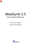
Portable transmitters are available in three different
forms: bodypack, handheld, and plug-on. (See Figure 2-2.)
Each of these has further variations of inputs, controls,
indicators, and antennas. The choice of transmitter type
is often dictated by the choice of input source: handheld
microphones usually require handheld or plug-on
transmitters while nearly all other sources are used with
bodypack types.
Bodypack (sometimes called beltpack) transmitters
are typically packaged in a shirt-pocket sized rectangular
housing. They are often provided with a clip that secures
Figure 2-2:
examples of transmitters (left to right: handheld, bodypack, plug-on)
9
of Wireless Microphone Systems
Selection and Operation
C
H A P T E R
2
Basic Radio Systems
Handheld transmitter controls are generally limited
called pre-emphasis, which is designed to minimize the
to a power switch, a mute switch, and gain adjustment.
apparent level of high frequency noise (hiss) that is
Again, tuneable models include some provision for
unavoidably added during the transmission. The "emphasis"
frequency selection. Indicators are comparable to
is a specifically tailored boost of the high frequencies.
those in bodypack transmitters: power status, battery
When this is coupled with an equal (but opposite)
condition, frequency. Handheld transmitter antennas
"de-emphasis" in the receiver, the effect is to reduce high
are usually concealed internally, though certain types
frequency noise by up to 10 dB. (See Figures 2-4 a & b.)
(primarily UHF) may use a short external antenna.
The second process is called "companding"
"Plug-on" transmit(compress/expand),
ters are a special type
which is designed to
designed to attach
compensate for the
directly to a typical
limited dynamic range of
handheld microphone,
radio transmission. The
effectively
allowing
part of the process
many standard microperformed in the transphones to become
mitter is "compression,"
"wireless." The transin which the dynamic
mitter is contained in a
range of the audio
Figure 2-3: general transmitter block diagram
small rectangular or
signal is reduced or
cylindrical housing with
compressed, typically by
an integral female XLR-type input connector. Controls and
a fixed ratio of 2:1. Again, when this is coupled with an equal
indicators are comparable to those found in bodypack
but opposite (1:2) "expansion" of the signal in the receiver,
types and the antenna is usually internal.
the original dynamic range of the audio signal is restored. A
Miniaturization of components has also resulted in a
voltage-controlled-amplifier (VCA) is the circuit element that
class of transmitters that are integrated directly into
provides both dynamic functions: gain is decreased in the
headworn microphones and lapel microphones as well as
compressor mode and increased in the expander mode.
units that can plug directly into the output connector of an
The gain change is proportional to the signal level change.
electric guitar. The trend toward smaller and more highly
Nearly all current wireless microphone systems employ
integrated devices is certain to continue.
some form of companding, allowing a potential dynamic
While transmitters vary considerably in their external
range greater than 100 dB. (See Figure 2-5.)
appearance, internally they all must accomplish the same
task: use the input audio signal to modulate a radio
carrier and transmit the resulting radio signal effectively.
Though there are many different ways to engineer wireless
transmitters, certain functional elements are common to
most current designs. It is useful to describe these
elements to gain some insight to the overall performance
and use of wireless microphone systems. (See Figure 2-3.)
TRANSMITTER: AUDIO CIRCUITRY
Figure 2-4a: pre-emphasis in transmitter
The first part of the typical transmitter is the input circuitry.
This section makes the proper electrical match between the
input source and the rest of the transmitter. It must handle the
expected range of input levels and present the correct
impedance to the source. Gain controls and impedance
switches allow greater flexibility in some designs. In certain
cases, the input circuitry also provides electrical power to the
source (for condenser microphone elements).
The signal from the input stage passes to the signal
processing section, which optimizes the audio signal in
several ways for the constraints imposed by radio
transmission. The first process is a special equalization
10
Figure 2-4b: de-emphasis in transmitter
H A P T E R
2
Basic Radio Systems
Figure 2-5: compander (2:1, fixed rate)
TRANSMITTER: RADIO CIRCUITRY
After processing, the audio signal is sent to a voltagecontrolled oscillator (VCO). This is the section that actually
converts the audio signal to a radio signal by the technique
called frequency modulation (FM). The (relatively) low
frequency audio signal controls a high frequency oscillator
to produce a radio signal whose frequency "modulates" or
varies in direct proportion to the audio signal.
The maximum value of modulation is called the
deviation and is specified in kilohertz (KHz). The amount of
deviation produced by the audio signal is a function of the
design of the transmitter. Systems with deviation greater
than the modulating frequency are called wideband, while
systems with deviation less than the modulating frequency
are called narrow band. Most wireless microphone
transmitters fall into the upper end of the narrow band
category. (See Figures 2-6 a & b.)
of Wireless Microphone Systems
A variation that is found in a few compander designs is
to divide the audio signal into two or more frequency bands.
Each band is then pre-emphasized and compressed
independently. In the receiver, de-emphasis and expansion
are applied separately to these same bands before
combining them back into a full-range audio signal. Though
more expensive, multi-band companding systems may
have a better ability to improve dynamic range and
apparent signal-to-noise ratio across the entire audio range.
A limitation of fixed-ratio companders is that the same
amount of signal processing is applied regardless of
signal level. Dynamics processors perform compression
or expansion functions based on an evaluation of the
"average" signal level, which fluctuates continuously.
Because this process is not instantaneous, the compander
action is not completely transparent. With good design,
audible "artifacts" are minimal but may become more
apparent when the signal level is extremely low. This
accounts for occasional "modulation" noise or background
noise intrusion that accompanies low-level audio signals,
especially when the radio signal itself is weak or noisy.
The performance of full-band companding systems can
be improved by first optimizing the measurement of the
average signal level. A "true RMS" detector is preferred,
since this technique most closely tracks the amplitude of a
full range audio signal, regardless of frequency response.
Further improvement can be realized by using leveldependent companding. For low level audio signals, little
or no processing is applied so there are no audible effects.
As the audio signal level increases, processing levels are
increased, so that potentially audible artifacts are masked.
Implementation of this scheme requires a high
performance VCA and close tolerance in the audio
sections of transmitters and receivers.
In many transmitters, an additional process called limiting
is applied to the audio signal. This is to prevent overload and
distortion in subsequent audio stages or to prevent
"overmodulation" (excessive frequency deviation) of the radio
signal. The "limiter" automatically prevents the audio signal
level from exceeding some preset maximum level and is
usually applied after pre-emphasis and companding.
Selection and Operation
C
Figure 2-6a: unmodulated FM signal spectrum
Figure 2-6b: modulated FM signal spectrum
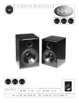
The "base" or unmodulated frequency of the oscillator for
a single frequency system is fixed. By design, the
frequency of the signal from the VCO (for a conventional,
crystal-controlled transmitter) is much lower than the desired
output frequency of the transmitter. In order to achieve a given
transmitter frequency the output from the VCO is put through
a series of frequency multiplier stages. These multipliers are
usually a combination of doublers, triplers, or even quadruplers.
For example, a transmitter that employs two triplers (for a 9x
multiplication) would use a VCO with a base frequency of 20
MHz to achieve a 180 MHz transmitted frequency. The
multipliers also function as amplifiers so that the output signal
is at the desired power level as well. (See Figure 2-7.)
11
of Wireless Microphone Systems
Selection and Operation
C
H A P T E R
2
Basic Radio Systems
A few tuneable transmitters use multiple crystals to
obtain multiple frequencies. However, the base frequency
of the VCO for most tuneable systems is adjustable by a
technique known as frequency synthesis. A control circuit
called a phase-locked-loop (PLL) is used to calibrate the
transmitter frequency to a reference "clock" frequency
through an adjustable frequency divider. By changing the
divider in discrete steps, the transmitter frequency can be
precisely varied or tuned over the desired range.
Frequency-synthesized designs allow the audio signal to
modulate the VCO directly at the transmitter frequency. No
multiplier stages are required. (See Figure 2-8.)
Figure 2-7: crystal-controlled transmitter
RECEIVER:
GENERAL DESCRIPTION
Receivers are available in both fixed and portable
designs. (See Figure 2-9.) Portable receivers resemble
portable transmitters externally: they are characterized by
small size, one or two outputs (microphone/line, headphone), minimal controls and indicators (power, level), and
(usually) a single antenna. Internally they are functionally
similar to fixed receivers, again with the exception of the
power supply (battery vs. AC). The important features
ofreceivers will be presented in the context of fixed units,
which exhibit a greater range of choices.
Fixed receivers offer various outward features: units
may be free standing or rack-mountable; outputs may
include balanced/unbalanced microphone or line level as
well as headphones; indicators for power and audio/radio
signal level may be present; controls for power and output
level are usually offered; antennas may be removable or
permanently attached. Like transmitters, receivers can
vary greatly in packaging, but inside they must achieve a
common goal: receive the radio signal efficiently and
convert it into a suitable audio signal output. Once again
it will be useful to look at the main functional elements of
the typical receiver. (See Figure 2-10.)
fixed
Figure 2-8: frequency-synthesized transmitter
Figure 2-9:
receiver examples
The last internal element of the transmitter is the
power supply. For portable transmitters, power is
generally supplied by batteries. Since the voltage level
of batteries falls as they are discharged, it is necessary
to design the device to operate over a wide range of
voltage and/or to employ voltage-regulating circuitry.
Most designs, especially those requiring a 9 V battery,
use the battery voltage directly. Others, typically those
using 1.5 V cells, have DC-to-DC converters that boost
the low voltage up to the desired operating value.
Battery life varies widely among transmitters, from just
a few hours up to twenty hours, depending on output
power, battery type, and overall circuit efficiency.
12
portable
RECEIVER: RADIO CIRCUITRY
The first section of receiver circuitry is the "front end."
Its function is to provide a first stage of radio frequency
(RF) filtering to prevent unwanted radio signals from
causing interference in subsequent stages. It should
effectively reject signals that are substantially above or
below the operating frequency of the receiver. For a single
frequency receiver the front end can be fairly narrow. For a
tuneable receiver it must be wide enough to accommodate
the desired range of frequencies if the front end filter itself
H A P T E R
2
Basic Radio Systems
Figure 2-10: general receiver block diagram
frequency and still yield the same difference frequency
when combined in the mixer. When the LO frequency is
lower than the received frequency the design is called
"low-side injection." When it is above it is called "high-side
injection." The sum and difference signals are then sent to
a series of filter stages that are all tuned to the frequency
of the difference signal.
This frequency is the
"intermediate frequency" (IF), so-called because it is lower
than the received radio frequency but still higher than the
final audio frequency. It is also the "defined amount" used
to determine the local oscillator frequency of the previous
section. The narrowly tuned IF filters are designed to
completely reject the sum signal, as well as the LO
frequency and the original received signal, and any other
radio signals that may have gotten through the front end.
The IF filters allow only the difference signal to pass
through. (See Figure 2-12.) This effectively converts the
received radio frequency (RF) signal to the much lower
intermediate frequency (IF) signal and makes subsequent
signal processing more efficient. This overall process is
called "downconversion."
Next, the (filtered) received signal and the local
oscillator output are input to the "mixer" section. The mixer,
in a radio receiver, is a circuit that combines these signals
in a process called "heterodyning." This process produces
two "new" signals: the first new signal is at a frequency
which is the sum of the received signal frequency and the
local oscillator frequency, while the second is at a frequency
which is the difference between the received signal
frequency and the local oscillator frequency. Both the sum
and the difference signals contain the audio information
carried by the received signal. It should be noted that the
LO frequency can be above or below the received
of Wireless Microphone Systems
is not tuneable. Filter circuits of various types ranging from
simple coils to precision "helical resonators" are used in front
end filters. The second receiver section is the "local
oscillator" (usually abbreviated as "LO"). This circuit
generates a constant radio frequency that is related to the
frequency of the received radio signal but differs by a
"defined amount." Single frequency receivers have a fixed
frequency local oscillator (LO), again using a quartz crystal.
Tuneable receivers have an adjustable LO, which generally
uses a frequency synthesis design. (See Figures 2-11 a & b.)
Selection and Operation
C
Figure 2-12: receiver, filter characteristic
Figure 2-11a: single conversion, crystal-controlled receiver
Figure 2-11b: single conversion, frequency-synthesized receiver
If only one LO and one mixer stage are used then only
one intermediate frequency is produced and the receiver
is said to be a "single conversion" type. In a "double
conversion" receiver the incoming signal is converted to
the final IF in two successive stages, each with its own LO
and mixer. This technique can provide increased stability
and interference rejection, though at significantly higher
design complexity and cost. Double conversion is more
common in UHF receiver designs where the received
signal frequency is extremely high. (See Figures 2-13 a & b.)
The IF signal is finally input to the "detector" stage
which "demodulates" or extracts the audio signal by one of
several methods. One standard technique is known as
"quadrature." When two signals are out of phase with each
other by exactly 90 degrees they are said to be in
quadrature. When such signals are multiplied together
and low-pass filtered the resulting output signal consists
13
of Wireless Microphone Systems
Selection and Operation
C
H A P T E R
2
Basic Radio Systems
only of frequency variations of the original input signal.
This effectively eliminates the (high-frequency) carrier
frequency leaving only the low-frequency modulation
information (the original audio signal).
In a quadrature FM detector the IF signal passes
through a circuit which introduces a 90 degree phase shift
relative to the original IF signal. The phase-shifted IF
signal is then multiplied by the straight IF signal. A
low-pass filter is applied to the product, which results in a
signal that is now the audio signal originally used to
modulate the carrier in the transmitter.
Figure 2-13a: double conversion, crystal-controlled receiver
Figure 2-13b: double conversion, frequency-synthesized receiver
RECEIVER: AUDIO CIRCUITRY
The demodulated audio signal undergoes
complementary signal processing to complete the
dynamic range recovery and noise reduction action begun
in the transmitter. For conventional compander systems, a
1:2 expansion is applied, followed by a high-frequency
de-emphasis. If a multi-band process was used in the
transmitter, the received audio is divided into the
corresponding bands, each band is expanded, the high
frequency band is de-emphasized, and finally the bands
are recombined to yield the full-range audio signal.
In the case of a signal-dependent compression
system, complementary variable expansion is used
14
followed by high frequency de-emphasis. Again, a
precision VCA with a true-rms audio level detector is required.
Finally, an output amplifier supplies the necessary
audio signal characteristics (level and impedance) for
connection to an external device such as a mixer input, a
recorder, headphones, etc. Typically, better receivers will
include a balanced output that can be switched between
line level and microphone level. Unbalanced outputs are
usually provided as well.
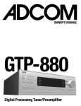
RECEIVER: SQUELCH
One additional circuit that is important to proper receiver
behavior is called "squelch" or muting. The function of this
circuit is to mute or silence the audio output of the
receiver in the absence of the desired radio signal. When
the desired signal is lost (due to multi-path dropout, excessive distance, loss of power to the transmitter, etc.) the
"open" receiver may pick up another signal or
background radio "noise." Typically, this is heard as "white"
noise and is often much louder than the audio signal from
the desired source.
The traditional squelch circuit is an audio switch
controlled by the radio signal level using a fixed or
manually adjustable threshold (level). (See Figure 2-14.)
When the received signal strength falls below this level the
output of the receiver is muted. Ideally, the squelch level
should be set just above the background radio noise level
or at the point where the desired signal is becoming too
noisy to be acceptable. Higher settings of squelch level
require higher received signal strength to unmute the
receiver. Since received signal strength decreases as
transmission distance increases, higher squelch settings
will decrease the operating range of the system.
One refinement of the standard squelch circuit is
referred to as "noise squelch." (See Figure 2-15.) This
technique relies on the fact that the audio from undesirable
radio noise has a great deal of high frequency energy
compared to a typical audio signal. The noise squelch
circuit compares the high frequency energy of the
received signal to a reference voltage set by the squelch
adjustment. In this system the squelch control essentially
determines the "quality" of signal (signal-to-noise ratio)
required to unmute the receiver. This allows operation at
lower squelch settings with less likelihood of noise if the
desired signal is lost.
A further refinement is known as "tone-key" or "tonecode" squelch. (See Figure 2-16.) It enables the receiver to
identify the desired radio signal by means of a supra- or
sub-audible tone that is generated in the transmitter and
sent along with the normal audio signal. The receiver will
unmute only when it picks up a radio signal of adequate
strength and also detects the presence of the tone-key.
H A P T E R
2
Basic Radio Systems
RECEIVER:ANTENNA CONFIGURATION
un-muted
squelch
threshold
RF
Level
RF signal
and noise
muted
Radio Frquency
RF Noise
Audio
Characteristic
AF
Noise
Level
muted
unmuted
Noise Squelch
Threshold
Audio
Characteristic
non-diversity (single antenna)
diversity (two antennas)
of Wireless Microphone Systems
Figure 2-14: threshold squelch
Fixed receivers are offered in two basic external
configurations: diversity and non-diversity. Non-diversity
receivers are equipped with a single antenna while
diversity receivers generally have two antennas. Both
systems may offer otherwise similar outward features:
units may be free standing or rack-mountable; outputs
may include balanced/ unbalanced microphone or line
level as well as head-phones; indicators for power and
audio/radio signal level may be present; controls for power
and audio output level are provided; antenna(s) may be
removable or permanently attached. (See Figure 2-17.)
Selection and Operation
C
Audio Frequency
Figure 2-17: examples of receivers
Figure 2-15: noise squelch
AF
Level
un-mute
tone squelch
threshold
mute
20 Hz
20 kHz
Audio Frequency
32 kHz
tone
Though diversity receivers tend to include more
features than non-diversity types, the choice of diversity vs.
non-diversity receiver is usually dictated by performance and
reliability considerations. Diversity receivers can significantly
improve both qualities by minimizing the effect of variations in
radio signal strength in a given reception area due to fading or
due to multi-path. Fading is a loss of signal strength at
excessive distance or because of shadowing or blocking of the
radio wave. Multi-path is a more complex phenomenon but
both mechanisms can adversely affect radio reception.
MULTIPATH
Figure 2-16: tone key squelch
This effectively prevents the possibility of noise from the
receiver when the desired transmitter signal is lost, even
in the presence of a (non-tone-key) interfering signal at
the same frequency. Turn-on and turn-off delays are
incorporated in the transmitter tone-key circuits so that
the transmitter power switch operates silently. When the
transmitter is switched on, the radio signal is activated
immediately but the tone-key is briefly delayed, keeping
the receiver muted until the signal is stable. This masks
any turn-on noise. When the transmitter is switched off,
the tone-key is deactivated instantly, muting the receiver,
but actual turn-off of the transmitted signal is delayed
slightly. This masks any turn-off noise. As a result, the
need for a separate mute switch is eliminated.
A necessary element in the concept of diversity radio
reception is the occurrence of "multi-path" effects in radio
transmission. In the simplest case, radio waves proceed
directly from the transmitting antenna to the receiving antenna
in a straight line. The received signal strength is only a function
of the transmitter power and the distance between the
transmitting and receiving antennas. In practice, this situation
could only occur outdoors on level, unobstructed terrain.
In most situations, however, there are objects that
attenuate radio waves and objects that reflect them. Since
both the transmitting and receiving antennas are essentially
omnidirectional, the receiving antenna picks up a varying
combination of direct and reflected radio waves. The reflected
waves and direct waves travel different distances (paths) to
arrive at the receiving antenna, hence the term multi-path.
(See Figure 2-18.)
15
of Wireless Microphone Systems
Selection and Operation
C
H A P T E R
2
Basic Radio Systems
RECEIVER:
DIVERSITY TECHNIQUES
Figure 2-18: multipath
These multiple paths result in differing levels, arrival times
and phase relationships between the radio waves. The net
received signal strength at any location is the sum of the
direct and reflected waves.
These waves can
reinforce or interfere with each other depending on their
relative amplitude and phase. The result is substantial
variation in average signal strength throughout an area.
This creates the possibility of degradation or loss of the
radio signal at certain points in space, even when the
transmitter is at a relatively short distance from the
receiver. Cancellation of the signal can occur when the
direct and indirect waves are similar in amplitude and
opposite in phase. (See Figure 2-19.)
Figure 2-19: signal level at two antennas with multipath
The audible effects of such signal strength variation
range from a slight swishing sound ("noise-up"), to severe
noises ("hits"), to complete loss of audio ("dropout"). Similar
effects are sometimes noted in automobile radio reception
in areas with many tall buildings. The "size" of a dropout
region is related to wavelength: in the VHF range (long
wavelength) dropout areas are larger but farther apart, while
in the UHF range (short wavelength) they are smaller but
closer together. For this reason, multi-path effects tend to be
more severe in the UHF range. These effects are
unpredictable, uncomfortable, and ultimately unavoidable
with single-antenna (non-diversity) receivers.
16
Diversity refers to the general principle of using
multiple (usually two) antennas to take advantage of the
very low probability of simultaneous dropouts at two
different antenna locations. "Different" means that the
signals are statistically independent at each location. This
is also sometimes called "space diversity," referring to the
space between the antennas.
For radio waves, this "de-correlation" is a function of
wavelength: a separation of one wavelength results in nearly
complete de-correlation. In most cases, at least one-quarter
wavelength separation between antennas is necessary for
significant diversity effect: about 40 cm for VHF systems and
about 10 cm for UHF systems. Some increased benefit may
be had by greater separation, up to one wavelength.
Separation beyond one wavelength does not significantly
improve diversity performance, but larger areas may be
covered due to more favorable antenna placement.
There are a number of diversity techniques that have
had some degree of success. The term "true" diversity has
come to imply those systems which have two receiver
sections, but technically, any system which samples the
radio field at two (or more) different locations, and can
"intelligently" select or combine the resulting signals is a
true diversity system.
The simplest technique, called "passive antenna
combining" utilizes a single receiver with a passive combination of two or three antennas. Antennas combined in this
manner create an "array," which is essentially a single
antenna with fixed directional characteristic. In its most
effective form (three antennas, each at right angles to the
other two) it can avoid complete dropouts, but with a
reduction of maximum range. This is because the array
output will almost always be less than the output of a
single antenna at the optimum location. If only two
antennas are used, dropouts can still occur in the event of
an out-of-phase condition between them. Cost is relatively
low but setup of multiple antennas can be somewhat
cumbersome. This is not a "true" diversity design.
(See Figure 2-20.)
A true diversity variation of this technique is "antenna
phase diversity." It also employs two antennas and a
single receiver but provides an active combining circuit for
the two antennas. This circuit can switch the phase of one
antenna relative to the other, eliminating the possibility of
phase cancellation between them. However, switching
noise is possible as well as other audible effects if
switching is incorrect. Range is sometimes greater with
favorable antenna combinations. Cost is relatively low.
Setup requires somewhat greater antenna spacing for
best results. (See Figure 2-21.)
H A P T E R
2
Basic Radio Systems
Figure 2-20: passive antenna combining
Figure 2-22: antenna switching
Figure 2-23: receiver switching
Figure 2-24: receiver combining
of Wireless Microphone Systems
Figure 2-21: antenna phase switching
The next variation, "antenna switching diversity," again
consists of a single receiver with two antennas. The receiver
includes circuitry that selects the antenna with the better
signal according to an evaluation of the radio signal.
Switching noise is possible but this system avoids the
possibility of phase cancellation between antennas
because the antennas are never combined. Range is the
same as for a single antenna system. Cost is relatively low
and setup is convenient. (See Figure 2-22.)
In both of these active antenna diversity approaches, the
switching decision is based on the received signal quality of
a single receiver section. When the signal quality falls below
some preset threshold, switching occurs immediately. If the
new antenna (or antenna combination) doesn’t improve the
reception, the receiver must switch back to the original state.
The lack of "predictive" ability often causes unnecessary
switching, increasing the chance of noise. The switching
speed is also critical: too fast and audible noise occurs, too
slow and a dropout may occur.
A recent antenna switching method offers predictive
diversity capability using a microcontroller to optimize
switching characteristics. A running average signal level
and a maximum signal level are calculated by analyzing
the change in signal level over time. Comparing the
current average signal level to the most recent maximum
signal level determines the switch action, based on typical
dropout characteristics. Small declines at high signal
levels indicate impending dropout, causing a switch to
occur. At moderate signal levels, larger decreases are
allowed before switching. At very low signal levels
switching is curtailed to avoid unnecessary noise. Of
course, if the signal level is increasing, no switching
occurs. The onset of dropout can be more accurately
recognized and countered, while eliminating switching
when there is little likelihood for improvement.
"Receiver switching diversity" is a widely used diversity
system. It consists of two complete receiver sections, each
with its own associated antenna, and circuitry that selects the
audio from the receiver that has the better signal. Switching
noise is possible but when properly designed these systems
can have very good dropout protection with little chance of
other audible effects due to incorrect selection. This is
because the system compares the signal condition at each
receiver output before audio switching occurs. Range is the
same as with single antenna systems. Cost is higher, but
setup is convenient. (See Figure 2-23.)
"Ratio combining diversity" also uses two complete
receiver sections with associated antennas. This design
takes advantage of the fact that, most of the time, the
signal at both antennas is useable. The diversity circuitry
combines the outputs of the two receiver sections by
proportionally mixing them rather than switching between
them. At any given moment, the combination is
proportional to the signal quality of each receiver. The
Selection and Operation
C
17
of Wireless Microphone Systems
Selection and Operation
C
H A P T E R
2
Basic Radio Systems
output will usually consist of a mix of the two audio
sections. In the case of loss of reception at one antenna,
the output is chosen from the other section. Excellent
dropout protection is obtained with no possibility of
switching noise since the diversity circuit is essentially an
intelligent panpot, not a switch. (See Figure 2-24.)
Signal-to-noise is improved by up to 3 dB. Range can be
greater than with single antenna systems. Cost is
somewhat higher, setup is convenient.
A properly implemented diversity system can yield
measurable improvements in reliability, range, and signalto-noise ratio. Although a comparable non-diversity
system will perform adequately most of the time in typical
setups, the extra insurance of a diversity system is worthwhile. This is particularly true if the RF environment is
severe (multipath), troubleshooting time is minimal (no
rehearsal), or dropout-free performance is required
(ideally always). The price difference is small enough that
diversity receivers are typically chosen in all but the most
budget-conscious applications.
ANTENNAS
In addition to the circuitry contained inside transmitters
and receivers, one critical circuitry element is often located
outside the unit: the antenna. In fact, the design and
implementation of antennas is at least as important as the
devices to which they are attached. Although there are
certain practical differences between transmitting and
receiving antennas there are some considerations that
apply to both. In particular, the size of antennas is directly
proportional to wavelength (and inversely proportional to
frequency). Lower radio frequencies require larger
antennas, while higher frequencies use smaller antennas.
Another characteristic of antennas is their relative
efficiency at converting electrical power into radiated
power and vice versa. An increase of 6 dB in radiated
power, or an increase of 6 dB in received signal strength
can correspond to a 50% increase in range. Likewise, a
loss of 6 dB in signal may result in 50% decrease in range.
Though these are best (and worst) case predictions, the trend
is clear: greater antenna efficiency can give greater range.
The function of an antenna is to act as the interface
between the internal circuitry of the transmitter (or
receiver) and the external radio signal. In the case of the
transmitter, it must radiate the desired signal as efficiently as
possible, that is, at the desired strength and in the desired
direction. Since the output power of most transmitters is
limited by regulatory agencies to some maximum level, and
since battery life is a function of power output, antenna
efficiency is critical. At the same time, size and portability of
transmitters is usually very important. This results in only a few
suitable designs for transmitter antennas. (See Figure 2-25.)
18
The smallest simple antenna that is consistent with
reasonable transmitter output is an antenna that is
physically (and electrically) one quarter as long as the
wavelength of the radio wave frequency being transmitted.
This is called a "1/4 wave" antenna. It takes different forms
depending on the type of transmitter being used. For some
bodypack transmitters, the antenna is a trailing wire cut to an
appropriate length. In other designs the cable that attaches
the microphone to the transmitter may be used as the
antenna. In either case, the antenna must be allowed to
extend to its proper length for maximum efficiency. The
effective bandwidth of this antenna type is great enough that
only about three different lengths are required to cover the
high-band VHF range. For transmitter applications requiring
even smaller antenna size a short "rubber duckie" antenna
is sometimes used. This type is still (electrically) a 1/4 wave
antenna, but it is wound in a helical coil to yield a shorter
package. There is some loss in efficiency due to the
smaller "aperture" or physical length. In addition, these
antennas have a narrower bandwidth. This may require up
to six different lengths to cover the entire high-band VHF
range for example.
Handheld transmitters generally conceal the antenna
inside the body of the unit, or use the outer metal parts of
the case as the antenna. In either design, the antenna is
rarely a true 1/4 wave long. This results in somewhat less
radiated power for a handheld transmitter with an internal
antenna than a comparable bodypack design with an
external antenna. However, antenna output is somewhat
reduced when placed close to the body of the user. Since
the antenna of a hand-held transmitter is usually at some
distance from the body, though, the practical difference
may be small. Plug-on type transmitters normally use the
microphone body and the transmitter case itself as the
antenna, though some manufacturers models have used an
external antenna. In practice the typical VHF transmitter
antenna is less than 10% efficient. UHF types may be
significantly better because the shorter wavelength of
these frequencies is more consistent with the requirement
for a small antenna.
internal
rubber-duckie
trailing wire
Figure 2-25: transmitter antenna examples
H A P T E R
2
Basic Radio Systems
Figure 2-26: 1/4 wave and 1/2 wave antennas UHF range
receiver or antenna distribution system. In addition, it is
resistant to the effects of electrical noise that might otherwise
be picked up at the interface.
When antenna size is an issue, such as for portable
receivers, the previously mentioned 1/4 wave rubber
duckie is an option. UHF designs can use 1/4 wave rubber
duckies because of the shorter wavelengths. Another
relatively small size remote antenna can be found in the form
of a 1/4 wave antenna with an attached array of radial
elements that function as an integral ground plane. Both of
these types are omnidirectional in the horizontal plane when
mounted vertically. For maximum efficiency, receiving
antennas should be oriented in the same direction as the
transmitting antenna. In the same way that a transmitter
antenna produces a radio wave that is "polarized" in the
direction of its orientation, a receiver antenna is most
sensitive to radio waves that are polarized in its direction of
orientation. For example, the receiving antenna should be
vertical if the transmitting antenna is vertical. If the
orientation of the transmitting antenna is unpredictable
(ie. handheld use), or if the polarization of the received wave
is unknown (due to multipath reflections) a diversity receiver
can have even greater benefit. In this case it is often
effective to orient the two receiving antennas at different
angles, up to perhaps 45 degrees from vertical.
Unidirectional antennas are also available for wireless
microphone systems. These designs are comprised of a
horizontal boom with multiple transverse elements and are
of the same general type as long range antennas for
television reception. They can achieve high gain (up to 10
dB compared to the 1/4 wave type) in one direction and
can also reject interfering sources coming from other
directions by as much as 30 dB. (See Figure 2-27.)
Two common types are the Yagi and the log-periodic.
The Yagi consists of a dipole element and one or more
additional elements: those located at the rear of the boom
are larger than the dipole element and reflect the signal
back to the dipole while those located at the front are
smaller than the dipole and act to direct the signal on to the
dipole. The Yagi has excellent directivity but has a fairly
narrow bandwidth and is usually tuned to cover just one
TV channel (6 MHz). The log-periodic achieves greater
bandwidth than the Yagi by using multiple dipole elements
in its array. The size and spacing between the dipoles
of Wireless Microphone Systems
In all of these designs, the radio wave pattern emitted
by the 1/4 wave antenna is omnidirectional in the plane
perpendicular to the axis of the antenna. For a vertically
oriented 1/4 wave antenna the radiation pattern is
omnidirectional in the horizontal plane, which is the typical
case for a trailing wire antenna. There is very little output
along the axis of the antenna. A three-dimensional
representation of the field strength from a vertical antenna
would resemble a horizontal doughnut shape with the
antenna passing through the center of the hole.
Recall that a radio wave has both an electric field
component and a magnetic field component. A vertically
oriented 1/4 wave transmitter antenna radiates an electric
field component that is also vertical (while the magnetic
field component is horizontal). This is said to be a
"vertically polarized" wave. Horizontal orientation of the
antenna produces a "horizontally polarized" wave.
In receiver applications, the antenna must pick up the
desired radio signal as efficiently as possible. Since the
strength of the received signal is always far less than that
of the transmitted signal this requires that the antenna be
very sensitive to the desired signal and in the desired
direction. However, since the size and location of the
receiver are less restrictive, and since directional pickup
may be useful, a much greater selection of antenna types
is generally available for receivers.
Again, the minimum size for adequate reception is 1/4
wavelength. A whip or telescoping antenna of this size is
supplied with most receivers, and it too is omnidirectional
in the horizontal plane when it is vertically oriented. An
important consideration in the performance of a 1/4 wave
receiving antenna is that its efficiency depends to some
extent on the presence of a "ground plane," that is, a metal
surface at least 1/4 wave long in one or both dimensions
and electrically connected to the receiver ground at the
base of the antenna. Typically, the receiver chassis or
receiver PC board to which the antenna is attached acts as
a sufficient ground plane. (See Figure 2-26.)
If more sensitivity is desired, or if it is necessary to mount
an omnidirectional antenna remotely from the receiver, 1/2
wave or 5/8 wave antennas are often used. These antennas
have a theoretical "gain" (increase of sensitivity) up to 3 dB
greater than the 1/4 wave antenna in some configurations.
This can translate into increased range for the system.
However, the 5/8 wave antenna, like the 1/4 wave type, only
achieves its performance with an appropriate ground plane.
Without a ground plane unpredictable effects may occur
resulting in asymmetric pickup patterns and potential signal
loss due to the non-ideal cable/antenna interface. A
properly designed 1/2 wave antenna does not require a
ground plane, allowing it to be remotely mounted with
relative ease. It can also maintain proper impedance at the
cable/antenna interface or can be directly attached to a
Selection and Operation
C
19
of Wireless Microphone Systems
Selection and Operation
C
H A P T E R
2
Basic Radio Systems
varies in a logarithmic progression so that at any given
frequency one or more dipoles are active while the others are
functioning as reflecting or directing elements, depending
on their size and location relative to the active element(s).
The longer the boom and the greater the number of
elements the greater is the bandwidth and the directivity.
Helical antennas are highly directional and also broadband.
Although these directional antennas are somewhat
large (3-5 ft. wide for VHF) and may be mechanically
cumber-some to mount, they can provide increased range
and greater rejection of interfering sources for certain
applications. It should also be noted here that these
antennas should be oriented with the transverse elements
in the vertical direction rather than the horizontal direction
(as would be used for television reception), again because
the transmitting antennas are usually also vertical.
possible. Antenna amplifiers can be used to compensate for
losses in long cable runs. (See Figure 2-33.)
In addition, the construction of the cable should be
considered: coaxial cables with a solid center conductor and
stiff insulator/shield are most suitable for permanent installation,
while cables with stranded conductors and flexible insulator/
shield should be used for portable applications which require
repeated setups. Finally, the number of connections in the
antenna signal path should be kept to a minimum.
ANTENNA DISTRIBUTION
1/2 wave
(with amplifier)
log
periodic
helical
Figure 2-27: examples of remote receiver antennas
ANTENNA CABLE
An important but often overlooked component of many
wireless microphone systems is the antenna cable.
Applications in which the receiver is located away from the
transmitter vicinity and/or within metal racks will require the use
of remote antennas and connecting cables. Compared to
audio frequency signals, the nature of radio frequency signal
propagation in cables is such that significant losses can occur
in relatively short lengths of cable. The loss is a function of the
cable type and the frequency of the signal. Figures 2-28 and
2-29 give some approximate losses for various commonly
used antenna cables at different radio frequencies. It may be
noted from this chart that these cables have a "characteristic"
impedance, typically 50 ohms. Ideally, for minimum signal loss
in antenna systems, all components should have the same
impedance: that is the antennas, cables, connectors and the
inputs of the receivers. In practice, the actual losses due to
impedance mismatches in wireless receiver antenna systems
are negligible compared to the losses due to antenna cable
length. Obviously, the benefits of even a high gain antenna
can be quickly lost using the wrong cable or too long a cable.
In general, antenna cable lengths should be kept as short as
20
Figure 2-28: comparison of coaxial cable types
The last component found in larger wireless receiver
systems is some form of antenna signal distribution. It is often
desirable to reduce the total number of antennas in multiple
systems by distributing the signal from one set of antennas to
several receivers. This is usually done to simplify system setup,
but can also improve performance by reducing certain types of
interference as will be seen later. There are two general types of
antenna distribution available: passive and active. Passive
antenna splitting is accomplished with simple in-line devices that
provide RF impedance matching for minimum loss. Still, a
single passive split results in about a 3 dB loss, which may
translate into some loss of range. (See Figure 2-31.) Multiple
passive splits are impractical due to excessive signal loss.
To allow coupling of antenna signals to more receivers
and to overcome the loss of passive splitters, active antenna
distribution amplifiers are used. These are also known as "active
antenna splitters" or "antenna multi-couplers." These devices
provide enough amplification to make up for splitter loss, they
Figure 2-29: coaxial antenna cable loss
at VHF and UHF frequencies
H A P T E R
2
Basic Radio Systems
Figure 2-31: passive antenna distribution
Figure 2-32a: active antenna distribution (one level)
LARGE ROOM/
MULTI-ROOM APPLICATIONS
Sometimes it is desired to use a single wireless
transmitter throughout a very large space or in
multiple rooms. It is difficult to get reliable reception
from transmitters in distant rooms or in extremely
large rooms, especially if there are many obstructions
or strong RF interference. A centrally located receiver
antenna may improve the situation. Line-of-sight
transmitter to receiver placement is always the
preferred setup.
If a diversity receiver with detachable antennas is used
the two antennas may be located in different rooms,
though this essentially reduces the receiver mode to
two non-diversity sections. If diversity reception is to
be maintained two antennas may be located in each
room with the use of an antenna combiner.
The "A" antenna in one room is combined with the "A"
antenna in the other room using an antenna
combiner. The "B" antennas are similarly connected
and the "A" and "B" combiner outputs are fed to the
receiver "A" and "B" antenna inputs. (See Figure 2-30.)
of Wireless Microphone Systems
usually operate at "unity" gain overall, that is, no net amplification
occurs. Though a multi-coupler is generally a separate accessory, some receiver designs are equipped with internal antenna
distribution when multiple receiver sections are incorporated in
the same chassis such as modular or card-cage systems.
Stand-alone active antenna splitters can typically feed
up to four receivers from one set of antennas. (See Figure
2-32a.) If more receivers are required, the outputs of one
distribution amplifier can feed the inputs of a second level set of
distribution amplifiers. (See Figure 2-32b.) Each of these can
then feed several receivers. Further active splits are impractical,
due to the potential for increased RF distortion and interference.
Selection and Operation
C
It is also possible to use multiple receivers and
antennas tuned to the frequency of a single transmitter.
The audio outputs of the receivers can then be
combined in a mixer to allow continuous pickup of the
signal from multiple locations. However, some type of
audio level control must be employed since the audio
level of such a system will increase by 3dB each time
the number of active receivers doubles. That is, if the
transmitter is picked up by two receivers at the same
time the overall audio level will be 3dB louder than
when picked up by only one receiver. Automatic
mixers can control this effect.
Figure 2-32b: active
antenna distribution (two level)
Figure 2-30: multi-room antenna distribution
Figure 2-33: antenna amplifiers
21
of Wireless Microphone Systems
Selection and Operation
C
H A P T E R
3
Wireless System Operation
FREQUENCY BANDS
FOR WIRELESS SYSTEMS
Existing wireless microphone systems transmit and
receive on a specific radio frequency, called the operating
frequency. Individual radio frequencies are found in
frequency "bands" which are specific ranges of frequencies.
Use of radio frequencies in the United States is
regulated by the FCC (Federal Communication
Commission). The FCC has designated certain bands of
frequencies and certain frequencies in those bands for use
by wireless microphones, as well as by other services. In
the US, the frequencies used for wireless audio systems
may be grouped into four general bands or ranges:
low-band VHF (49-108 MHz), high-band VHF (169-216
MHz), low-band UHF (450-806 MHz) and high-band UHF
(900-952 MHz). VHF stands for "Very High Frequency,"
UHF stands for "Ultra High Frequency." (See Figure 3-1.)
Figure 3-1: wireless frequency bands in the United States
The FCC further determines who can operate in
each band and who has priority if more than one user
is operating.
"Primary" users include licensed
broadcasters (radio and television) and commercial
communications services (2-way radio, pagers, and
cellular telephones). Wireless microphone operators
are always considered to be "secondary" users. In
general, priority is given to primary users: secondary
users may not interfere with primary users, and
secondary users may be subject to interference from
primary users.
On the subject of licensing, it should be noted that
while manufacturers must be licensed by the FCC to
sell wireless equipment, it is the responsibility of the
operator to observe FCC regulations regarding their
actual use.
We will briefly describe each band and its
advantages and disadvantages for wireless
microphone system operation, based on the designated
users of the band, the physical characteristics of the
band, and the regulatory limitations of the band.
22
THE VHF BAND
At the beginning of the low-band VHF range is the 49
MHz region, used not only by wireless microphones but
also by cordless telephones, walkie-talkies, and radio
controlled toys. 54-72 MHz is occupied by VHF television
channels 2-4. The 72 MHz area is used by "assistive
listening" type wireless microphone systems. 76-88 MHz
is assigned to VHF television channels 5 and 6. At the
top, 88-108 MHz is the commercial FM radio broadcast
band. (See Figure 3-2.) All of these regions have been
used at one time or another for wireless microphone
systems. Allowable deviation limits (typically up to
15KHz) can accommodate high-fidelity audio (the same
as for FM broadcast). The propagation of these waves
through the air is very good, as is their ability to pass
through many non-metallic substances (a result of their
relatively long wavelength). The most attractive feature of
operation in this band is low equipment cost.
Except for assistive listening systems, however,
low-band VHF is not recommended for serious
applications. Due to the large number of primary and
secondary users, and high levels of general radio
frequency (RF) "noise," this band is prone to
interference from many sources. Transmitter power is
limited to less than 50 mW (except in the 72-76 MHz
range where up to 1 watt is allowed for assistive
listening systems). Finally, the minimum proper
antenna size for units in this range can be over one
meter long (one quarter of a five meter wave), which
can severely limit portability and/or efficiency.
Next is the high-band VHF range, widely used for
professional applications, in which quality systems are
available at a variety of prices. In the US, the
high-band VHF range is divided into two bands, which
are available to wireless microphone users. The first of
these, from 169-172 MHz, includes eight specific
frequencies designated by the FCC (Part 90.263b or
just "Part 90") for wireless microphone use by general
business. These frequencies are often referred to as
Figure 3-2: VHF allocations in the United States (30-300 MHz)
H A P T E R
3
Wireless System Operation
Finally, these frequencies are not generally legal outside of
the US and Canada.
The larger part of the high-band VHF region is 174-216
MHz. This band is designated by the FCC for use by
broadcasters and by commercial film/video producers ("Part
74"). The primary users of this band are VHF television
channels 7-13. Once again, high quality audio is possible
within legal deviation limits (+15 kHz). The 50 mw power
restriction is the same as for low-band, propagation losses
are still minimal, and acceptable quarter-wave antenna sizes
range down to less than one-half meter.
The possibility of interference from other secondary
users and general RF noise exists, but it is much less
likely than for low-band frequencies. In addition,
although this range includes powerful primary users
(television channels 7-13), there are ample frequencies
available (locally unused television channels) in almost
any part of the US.
UHF VS. VHF
deviation, for potentially greater audio dynamic range. In
addition, greater transmitter power is allowed (up to 250 mw).
Finally, the available radio spectrum for UHF wireless
microphone system use is eight times greater than for
high-band VHF. This allows for a much larger number of
systems to be operated simultaneously.
In practice, the effectively greater deviation limits of UHF
are not generally used because of the resulting reduction in
the number of simultaneous systems that may operated:
the corresponding increased occupied bandwidth of each
system uses up more of the available frequency range.
Also, use of increased transmitter power is rare due to the
resulting severely decreased battery life and to the
increased potential of mutual system interference. Even
with limited deviation and power, however, the capability for
an increased number of simultaneous systems is a
significant benefit in certain applications. This is especially
true since UHF systems can generally be used in
conjunction with VHF systems at the same location without
mutual interference.
The primary economic difference between VHF and
UHF operation is the relatively higher cost of UHF
equipment. Typically, it is more difficult and hence more
expensive to design and manufacture UHF devices. In
many ways this is a consequence of the behavior of high
frequency (short wavelength) radio signals. This cost
differential applies to antennas, cables, and other
accessories as well as to the basic transmitter and receiver.
Currently, though, economies of scale have reduced this
premium substantially so that it is now possible to produce
basic UHF systems at prices comparable to VHF. However,
advanced features and performance tend to remain in the
province of high-end UHF products.
Like the VHF region, the UHF region contains several
bands that are used for wireless microphone systems.
However, certain physical, regulatory, and economic
differences between VHF and UHF regions should be
noted here. The primary physical characteristic of UHF
radio waves is their much shorter wavelength (one-third to
two-thirds of a meter). The visible consequence of this is
the much shorter length of antennas for UHF wireless
microphone systems. Quarter-wave antennas in the UHF
range can be less than 10 cm.
There are other consequences of the shorter UHF
wavelength. One is reduced efficiency of radio wave
propagation both through the air and through other nonmetallic materials such as walls and human bodies. This
can result in potentially less range for a UHF signal
compared to a VHF signal of the same radiated power.
"Line-of-sight" operation is more important in the UHF
range. Another consequence is the increased amount of
radio wave reflections by smaller metal objects, resulting in
comparatively more frequent and more severe
interference due to multi-path (dropouts). However,
diversity receivers are very effective in the UHF band, and
the required antenna spacing is minimal. Finally, the
signal loss in coaxial antenna cables is greater in the UHF
range. Amplifiers and/or low-loss cable may be required
in UHF antenna systems.
While the regulations for users and for licensing are
essentially the same in the VHF and UHF bands (FCC Part 90),
regulations for the equipment allow two potential
differences. For FM signals in the UHF band, greater occupied
bandwidth is allowed. This effectively permits greater FM
of Wireless Microphone Systems
"travelling frequencies," because they can (theoretically) be
used throughout the US without concern for interference
from broadcast television. Legal limits of deviation (+/_12
KHz) allow high quality audio transmission. Once again,
power is limited to 50 mw. Propagation characteristics are
good, and antenna length is more manageable at about
one-half meter for a quarter-wave type.
Unfortunately, the primary users in this band include
many business band and government operations such as
digital paging services, forestry, hydro-electric power
stations, and the Coast Guard. Since the secondary user
category is not restrictive, the potential for interference
from both primary and other secondary users is always
present. Also, general RF noise is still fairly strong in this
band. In addition, due to the limitation of available
frequency bandwidth, and the spacing of the prescribed
eight frequencies, it is only feasible to operate, at most, two
or three units simultaneously on travelling frequencies.
Selection and Operation
C
23
THE UHF BAND
The low-band UHF range of frequencies may be considered as two overlapping bands: low (450-536 MHz)
and high (470-806). The primary users of these bands are
business services such as land mobile radio and pagers
(450-536 MHz) and UHF television channels 14-69 (470806 MHz). As in the high-band VHF region, unused
television channels are allotted for wireless microphone
system use by broadcasters and video/film producers.
There are many primary users (business and television) in
the low part of the band, but interference from primary
users is rare in the high (non-business) part of the band,
due to the relatively small number and shorter range of
UHF television stations. Other secondary users and RF
noise are also less likely at these frequencies.
high power primary users, international availability
(almost), no bandwidth/modulation scheme limits, and no
license requirement. Unfortunately, these same features
have already attracted a considerable number of users:
cordless telephones and short-to-medium range wireless
network applications such as "Bluetooth" and "Wi-Fi." Add
to this the existing base of 2.4 GHz users that includes the
ISM (Industrial, Scientific, and Medical) band as well as the
lowly microwave oven and it would appear that this band
may be subject to the same fate as its other unlicensed
predecessors. However, many of the devices in this band
use a "spread-spectrum" modulation scheme, which
reduces mutual interference to some extent. It remains to
be seen how they may coexist with wireless audio systems.
Finally, it should be kept in mind that the allocation of
these bands is always subject to change as demand for
spectrum increases. In the US, for example, proposals to
designate unused VHF TV channels in major urban areas
for use by land-mobile services are being considered.
Some unused high-band UHF TV channels are being
re-allocated for public safety radio systems while others
will be auctioned off to commercial wireless
communication services. As always, manufacturers and
users must continue to evaluate these developments for
their impact on wireless system operation.
FREQUENCY SELECTION
Like high-band VHF, licensing is still required in this
UHF band. The required minimum quarter-wave antenna
size for UHF radio waves is 9-16 cm (only one-quarter to
one-third that for VHF). Equipment is moderately
expensive and diversity systems are strongly
recommended, but high quality audio can be achieved
along with a large number of simultaneous systems.
The high-band UHF range (900 MHz and above)
includes studio-to-transmitter links (STL), other primary
users, and a host of secondary users. (See Figure 3-3.) This
band offers additional channels and potentially less
interference from RF noise, as well as antenna lengths of
less than 9 cm. Other operating characteristics are similar
to low-band UHF. However, secondary users are allowed to
operate without licensing in much of this range. Though
there have been some wireless microphone products in this
unlicensed range, it has now largely been occupied by
consumer products such as cordless telephones and home
audio/video repeaters. As in the cases of 49 MHz and
169-172 MHz ("traveling" frequencies), the proliferation of
consumer wireless products has rendered the 900 MHz
band all but unusable for professional wireless operations.
Recently, the 2.4 GHz band has attracted some
interest for wireless microphone use. Potential advantages
of this band are: very short antennas (less than 4 cm.), no
Selecting the operating frequency of a wireless audio
system is a two-step process: first, choose an appropriate
radio frequency band; second, choose the appropriate
operating frequency (or frequencies) within that band. As
indicated above, there is a finite number of wireless
microphone systems that may be used simultaneously in
any one frequency range. The reasons for this
limitation are several and they fall under the general topic
of frequency coordination or "compatibility." We will define
these factors and examine each in terms of origin, effects,
H A P T E R
3
Wireless System Operation
SYSTEM COMPATIBILITY
OPERATING FREQUENCY
INTERACTIONS: INTERMODULATION
A single wireless microphone system can theoretically
be used on any open operating frequency. When a
second system is added it must be on a different
operating frequency in order to be used at the same time
as the first. This limitation arises from the nature of radio
receivers: they cannot properly demodulate more than
one signal on the same frequency. In other words, it is not
possible for a receiver to "mix" the signals from multiple
transmitters. If one signal is substantially stronger than the
others it will "capture" the receiver and block out the other
signals. If the signals are of comparable strength none of
them will be received clearly.
The effect of this is often heard in automobile radios
when travelling out of range of one station and into the
range of another station at the same frequency. The
receiver will switch back and forth between the two
stations as their relative signal strength changes, often with
considerable noise and distortion. The result is that neither
station is listenable when the signals are nearly equal.
If the wireless microphone systems must be on
different frequencies, how "different" should they be? The
limiting characteristic of the receiver in this regard is its
"selectivity" or its ability to differentiate between adjacent
frequencies. The greater the selectivity the closer
together the operating frequencies can be. Most
manufacturers recommend a minimum frequency
difference of 400 kHz (0.4 MHz) between any two systems.
When a third system is added to the group it must of
course be at least 400 kHz away from each of the existing
systems. However, it is now necessary to consider other
potential interactions between the transmitters to insure
that all three systems will be compatible with each other.
The most important type of interaction is called
intermodulation (IM), and it arises when signals are
applied to "non-linear" circuits. (See Figure 3-4.)
A characteristic of a non-linear circuit is that its output
contains "new" signals in addition to the original signals
that were applied to the circuit. These additional signals
Figure 3-4: linear vs. non-linear circuits
are called IM products and are produced within the circuit
components themselves. The frequencies of IM products
are mathematically related to the original transmitter
frequencies. Specifically, they consist of sums and
differences of the original frequencies, multiples of the
original frequencies, and sums and differences of the
multiples. Non-linear circuits are intrinsic to the design of
wireless components and include the output stages of
transmitters and the input stages of receivers. The "mixer"
stage at the receiver input is an example of a non-linear
circuit: recall that it is designed to produce a "difference"
frequency that becomes the intermediate frequency (IF)
for subsequent stages.
IM can occur when transmitters are in close proximity
to each other. The signal from each transmitter generates
IM products in the output stage of the other. These new
signals are transmitted along with the original signals and
can be picked up by receivers operating at the
corresponding IM frequencies. (See Figure 3-7.)
IM can also occur when transmitters are operated very
close to receivers. In this case IM products are generated
in the receiver input stage which can interfere with the
desired signal or be detected by the receiver if the desired
signal (transmitter) is not present.
The strongest IM products are the two so-called 3rd
order products produced by two adjacent transmitters
operating at frequency f1 and frequency f2, where f1 is lower
than f2. The resulting IM products may be calculated as:
IM1 = (2 x f1) – f2
IM2 = (2 x f2) –f1
If the interval between f1 and f2 is F, then IM1 = f1 – F and
IM2 = f2 + F. That is, one IM will appear exactly at interval F
above the upper frequency f2 while the other IM will appear
exactly at interval F below the lower frequency. For example, if
f1 = 180MHz and f2 = 190MHz, then F = 10MHz. Thus,
IM1 = 170MHz and IM2 = 200MHz. (See Figure 3-5.)
In addition to IM products generated by interaction
between two transmitters, other IM products are generated by
interaction between three transmitters in a similar fashion.
(See Figure 3-6.) In order to avoid potential IM problems most
manufacturers recommend a minimum margin of 250 kHz
(0.25 MHz) between any 3rd order IM product and any
of Wireless Microphone Systems
The two main areas of concern are: interaction
between transmitters and receivers related to their operating
frequencies, and interactions between transmitters and
receivers related to their internal frequencies. The first
class of interactions is the more important one and may
occur in any group of wireless microphone systems. It is
also the one more cumbersome to calculate. The second
class of interactions is less problematic and is also
relatively easy to predict. However, it is determined by
specific system characteristics.
Selection and Operation
C
25
of Wireless Microphone Systems
Selection and Operation
C
H A P T E R
3
Wireless System Operation
operating frequency. This further restricts available frequency
choices as the number of simultaneous systems increases.
It should be apparent from this discussion that the
prediction of potential compatibility problems due to
IM products is best left to computer programs.
The complexity increases exponentially for additional
systems: a group of 10 wireless microphone systems
involves thousands of calculations. See Appendix 1 for
details on calculation of IMD products.
INTERNAL FREQUENCY
INTERACTIONS:
LO, IF, CRYSTAL MULTIPLIERS
Figure 3-5: two-transmitter intermodulation
In addition to frequency conflicts due to intermodulation
between operating frequencies there are certain other sources
of potential conflicts due to the various "internal" frequencies
present in the normal operation of transmitters and receivers.
These differ from manufacturer to manufacturer and even from
system to system from the same manufacturer.
Figure 3-8: local oscillator (LO) interference
Figure 3-6: three-transmitter intermodulation
Figure 3-7: two-transmitter IMD strength vs.
transmitter separation
26
One such source is the local oscillator (LO) of the receiver
itself. Although this is a low-level signal which is generally
confined within the receiver, it is possible for the local
oscillator of one receiver to be picked up by another receiver
tuned to that LO frequency if they or their antennas are in close
proximity to each other (stacked, for instance). For example,
assuming a typical intermediate frequency (IF) of 10.7 MHz, a
receiver tuned to 200.7 MHz would have its LO operating at
190.0 MHz. Another receiver tuned to 190 MHz should not be
used close to the first receiver because the second unit could
pick up the LO of the first, especially if the 190 MHz transmitter
is turned off or is operating at a great distance. (See Figure
3-8.) Good design and shielding in receivers and physical
separation of receivers will minimize the possibility of LO
interference. For multiple units, active antenna splitters will
effectively isolate antenna inputs from each other. However, it
is still recommended that operating frequencies be chosen to
avoid LO frequencies by at least 250 KHz.
An "image" frequency is another source of possible
interference. In a receiver, recall that the frequency of the
local oscillator (LO) always differs from the frequency of the
H A P T E R
3
Wireless System Operation
received signal by an amount equal to the intermediate
frequency (IF). Specifically, the operating frequency is
above the local oscillator frequency by an interval equal to
the IF. When these two frequencies are applied to the mixer
section (a non-linear circuit) one of the output frequencies of
the mixer is this difference frequency (the IF), which is the
tuned frequency of the subsequent IF stage filters.
of Wireless Microphone Systems
10.7 MHz, a receiver tuned to 200.7 MHz would have its LO
at 190.0 MHz. A signal from another transmitter at 179.3
MHz would appear as an image frequency since it is 10.7
MHz below the LO frequency or 21.4 MHz below the
operating frequency.
The image frequency differs from the operating
frequency by an amount equal to two times the intermediate
frequency (2 x IF). (See Figures 3-9 a & b.) The image
frequency will be below the operating frequency for a high-side
injection receiver and above the operating frequency for a
low-side injection receiver. Thus the image frequency for the
typical single conversion receiver is at least 20 MHz away from
the operating frequency. Double conversion receivers, which
have a relatively high first IF (50 MHz typical), have image
frequencies which are even farther (>100 MHz typical) away
from the operating frequency. In most cases, the front end of
the receiver should be able to reject an image frequency
unless it is extremely strong. Nevertheless, it is recommended
that operating frequencies be chosen to be at least 250 KHz
from any image frequency.
Selection and Operation
C
Figure 3-9a: image frequency interference (low-side injection)
Figure 3-10: crystal harmonics
Figure 3-9b: image frequency interference (high-side injection)
If the frequency of a second signal is at the same
interval below the local oscillator frequency, the difference
between this second frequency and the LO frequency
would again be equal to the intermediate frequency (IF).
The mixer stage does not discriminate between "positive"
or "negative" frequency differences. If this second (lower)
frequency enters the mixer stage, it will result in another
(difference) signal getting to the IF stages and causing
possible interference. This lower frequency is called the
"image" of the original frequency. Again, assuming an IF of
The last internal frequency issue concerns the VCO in
crystal controlled transmitters. Recall that the actual VCO
frequency is a relatively low radio frequency that is
multiplied to obtain the final transmitter frequency. A small
amount of the original crystal frequency remains after each
multiplier stage. Thus the output signal includes not only
the final operating frequency but also low-level "spurs" or
spurious emissions due to the multipliers. These spurs
occur above and below the operating frequency at
intervals equal to "harmonics" (multiples) of the original
crystal frequency.
For example, assuming a 9 x multiplier, a 180 MHz
transmitter would have a 20 MHz crystal frequency. This
would produce spurs at 160 MHz and 200 MHz, 140 MHz
and 220 MHz, etc. Good transmitter design will minimize
the amplitude of such crystal harmonics but, again,
additional receivers should be chosen to avoid these
frequencies by at least 250 KHz. (See Figure 3-10.)
Frequency-synthesized transmitters do not produce
spurious emissions of this type because they do not employ
27
of Wireless Microphone Systems
Selection and Operation
C
H A P T E R
3
Wireless System Operation
multipliers. However, both types of transmitters can
produce other spurious emissions due to power regulating
circuitry, parasitic oscillations, carrier harmonics, etc. These
emissions can all be controlled through careful design.
It can be seen that the calculation of both local
oscillator conflicts and image frequencies depends on the
intermediate frequency (IF) of the receiver while calculation
of crystal harmonics depends on the number of multipliers
in the transmitter. If receivers with different IFs or
transmitters with different multipliers are being used
together (i.e. units from different manufacturers) this must be
taken into account in compatibility analysis. Unfortunately,
only a few proprietary computer programs for frequency
selection have this capability. Input to most of these
programs assumes that all units are of the same design. For
this reason, accurate prediction of compatibility between
systems of different design is not always possible.
NON-SYSTEM
RADIO INTERFERENCE
Figure 3-11a: analog television channel spectrum
Even though a group of wireless microphone
systems may be carefully chosen to avoid mutual
interference there always exists the possibility of
interference from non-system sources. These sources fall
into two categories: broadcast (including television and
other defined radio sources) and non-broadcast (narrow
band or broadband sources of radio noise). We will look
at each of these sources in terms of potential problems
and possible solutions.
BROADCAST TELEVISION
In the US, and some other countries, broadcast
television is undergoing a transition from analog to
digital. This transition affects wireless audio systems in
several ways: more "occupied" TV channels, no "open"
space in DTV channels, and future "re-allocation" of
existing TV channels.
Television stations are presently broadcasting both
traditional analog signals and digital signals (DTV).
Though both types of signal occupy similar channel
"blocks", the nature of the signal within the channel is
quite different. An analog TV transmission consists of
three separate signals, each at a specified carrier
frequency within a 6 MHz block (in the US). (See Figure
3-11a.) The picture or "video" information is an AM signal at 1.25 MHz above the bottom (low frequency end)
of the block. The sound or "audio" information is an FM
signal located at 0.25 MHz below the top (high
frequency end) of the block. The color or "chroma"
information is an AM signal at 3.58 MHz above the
video signal. The energy distribution and occupied
28
bandwidth of these three signals is not equal: the
video signal has the highest power and widest
bandwidth, followed by the audio signal and finally the
chroma signal with the lowest power and smallest
bandwidth.
Figure 3-11b: digital television channel spectrum (DTV)
A digital TV transmission consists of a continuous
signal that occupies the entire 6 MHz block. (See Figure 311b.) All of the video, audio, and color information is
digitally encoded into this signal along with a variety of
other data, control, and secondary audio information. It is
possible for the DTV transmission to carry one
high-definition television signal (HDTV) or up to four standard-definition television signals. The energy distribution
within a DTV channel is essentially uniform. However, the
average signal level of a DTV transmission is somewhat
less than the levels of the video and audio signals in an
analog TV transmission.
As indicated previously, the primary users of both
high-band VHF and low-band UHF frequencies are
broadcast television stations. In the US these are VHF
TV channels 7 through 13 and UHF TV channels 14
through 69. Each TV channel is allotted a 6 MHz block
for its transmission. VHF channel 7 begins at 174.0
MHz and extends to 180.0 MHz, channel 8 occupies
H A P T E R
3
Wireless System Operation
country. As the
distribution of
Figure 3-12: major analog and digital
TV channels in Chicago and Milwaukee
vacant channels changes from city to city it is almost
inevitable that a "touring" system will experience
interference from a television station in some location. For
example, Chicago has active high-band VHF TV channels
7, 9, and 11. Therefore, a suitable setup for use there would
include wireless microphone systems on frequencies
corresponding to TV channels 8, 10, and/or 12.
If this setup is taken to Milwaukee, which has TV
channels 8 and 10, it is likely that one or more of the units
would experience interference, especially if used outdoors
or even indoors in a building near one of those television
transmitters. A similar situation may also occur in the UHF
band though the distribution of UHF TV channels is not
quite as dense. (See Figure 3-12.)
The effects of interference from television broadcast
are dependent on the type of television signal (analog or
DTV), the strength of the television signal, as well as the
location and the operating frequency of the wireless
microphone system.
Direct conflicts with any of the three signals that make up
an analog TV transmission can produce noise, distortion, and
short range or dropout. Pickup of the video or chroma signals
(which are AM) can cause distinct "buzz" in the wireless
receiver, while pickup of the audio signal (FM) will result in the
TV sound being heard. It is sometimes possible to use
frequencies just above or just below the chroma carrier since
that signal has the least power and the narrowest occupied
bandwidth, though this is not always reliable.
Direct conflict with a DTV signal usually causes short
range or dropouts. It is not possible for an analog receiver
to "hear" anything from a digital transmission but the DTV
signal acts as a very strong broadband noise source. In
some systems this may result in increased noise or
distortion in the audio output. There are no "unoccupied"
frequencies in a DTV signal so it may not be possible to
operate anywhere within a very strong DTV channel.
The most effective solution for broadcast television
interference is to avoid using frequencies of local active TV
channels. Television transmitters may operate at power
levels up to several million watts while wireless
microphone systems typically have only 50 mw (fifty onethousandths of one watt!) of output power. For this reason
it is unwise to choose wireless microphone system
frequencies that fall in an active local TV channel block.
"Local" is generally considered to be up to 50 miles,
depending on the coverage area of the particular TV
transmitter and on the location of the wireless microphone
system. Indoor setups are at less risk than outdoor setups
because building structures will usually strongly attenuate
TV signals. Nevertheless, since the locations and
assignments of television stations are well known it is
relatively easy to choose fixed wireless microphone
system frequencies to avoid them in a particular area.
of Wireless Microphone Systems
180-186 MHz and so on up to channel 13 at 210-216
MHz. UHF channel 14 begins at 470 MHz and extends
to 476 MHz with successive channels up to channel 69
at 800-806 MHz.
The 6 MHz/TV channel block is found in the US, the
rest of North America, South America and Japan.
Other countries, most of Europe and India for example,
use a 7 MHz/TV channel block, while France and
China, among others, use an 8 MHz/TV channel block.
For analog transmission in these other systems, the
video and audio signals are located at the same
frequencies relative to the channel boundaries as in the
6 MHz systems, but the frequency of the chroma signal
differs slightly in each to accommodate the various
color systems: NTSC (6 MHz), PAL (7 MHz), and
SECAM (8 MHz). DTV proposals for all systems
specify the appropriate TV channel block sizes.
To avoid potential interference between broadcast
television stations, regulatory agencies have not
allowed adjacent analog TV channel operation in a
given geographic area. For example, in the US, if a
local analog TV channel 9 existed, then analog
channels 8 and 10 would be vacant. These vacant
channels could then be used by wireless microphone
systems with little concern for television interference.
Historically, this guaranteed the existence of certain
"unused" TV channels in a given area. The advent of DTV
has removed this guarantee. DTV channels are allowed to
exist adjacent to each other and also adjacent to existing
analog TV channels. This has resulted not only in more
occupied TV channels but also in difficulty using earlier
"pre-selected" frequency compatibility schemes.
Many manufacturers pre-select groups of wireless
microphone system frequencies based on the availability of
vacant TV channels. They also have information on TV
channel distribution throughout the US. It is usually sufficient
to indicate the destination of the wireless equipment at the time
that it is specified in order to avoid broadcast television
interference.
Chicago
Milwaukee
One conseAnalog DTV Analog DTV
quence of the
2
3
4
28
relatively dense
5
29
6
33
TV channel
7
52
10
8
distribution in the
9
19
12
34
US is that it is not
11
47
18
61
generally possible 20
21
24
25
to use a given set 26
27
36
27
of fixed-frequency 32
31
32
35
38
43
55
40
wireless micro50
51
58
46
phone systems
66
53
everywhere in the
Selection and Operation
C
29
of Wireless Microphone Systems
Selection and Operation
C
H A P T E R
3
Wireless System Operation
DTV VS. WIRELESS SYSTEMS
In the United States, the Federal Communications
Commission (FCC) is currently supervising the transition
of broadcast television from its traditional analog format
to an all-digital format (DTV). In the process, the
commission is also mandated to increase efficient use of
TV spectrum and to increase the amount of spectrum
available for public safety and other wireless services.
Therefore, the transition provides for consolidation of the
broadcast spectrum and for the reallocation of the
resulting open spectrum to other uses.
The FCC intends to consolidate all broadcast
television into a "core" band, currently TV Channels
2-51. Proposed and existing TV stations above
Channel 51 will eventually migrate into the core
band. All former television spectrum above Channel
51 is to be auctioned by competitive bidding, with
the exception of new "public safety" bands.
Specifically, the public safety bands total 24 MHz in two
"paired" bands: 764-776 MHz (TV 63-64) for fixed
transmitters and 794-806 MHz (TV 68-69) for mobile
transmitters. The remaining spectrum, 698-764 MHz
(TV 52-62) and 776-794 MHz (TV 65-67), will be
allocated for commercial fixed and mobile services as
well as possible "new" broadcast services.
Timetable for DTV transition:
Telecommunications Act of 1996 provides for
digital television
April 3, 1997: existing TV stations (1600+)
assigned a second channel for DTV
As of January 1, 2003 there were 700+ digital stations
on-air, in addition to the 1600+ existing analog stations.
Though not quite on schedule, the DTV transition is
proceeding. The primary concern for wireless system
operators remains the same: the potential loss of
operating spectrum due to interference from television
transmitters, whether digital or analog. Though digital
and analog signals differ in some respects, the defense
is the same: avoid operating in active TV channels. The
difficulty is the increased number of TV transmitters
(potentially double) during the DTV transition period
and the increased density of TV transmitters in the
"core" spectrum after the transition period.
Though it is likely that there will be a net reduction in the
final number of television stations after the
transition period, the core spectrum (TV 2-51) will
certainly be more crowded than at present, and the
former television bands will host various new radio
services. However, it is expected that wireless systems
will continue to be allowed to operate as low power auxiliary stations (LPAS) throughout their original spectrum.
Thus, for near term applications, wireless system users only
need to keep track of DTV stations as they go
on-air during the transition period. For long term
applications, however, wireless system users will have to
contend with the spectrum landscape after transition:
broadcast transmitters will be in place but commercial and
public safety services will have to be taken into account as
they come on-line. Ultimately, the existing VHF and UHF
bands still appear to be the best choice for wireless system
operation, but practical equipment will likely have to employ
advanced frequency agility or other technologies to make
the best use of scarce spectrum resources.
May 1, 1999: 40 top-10 market stations
required to be on-air
November 1, 1999: 120 top-thirty stations
required to be on-air
May 1, 2002: all commercial stations
required to be on-air
May 1, 2003: all non-commercial stations
required to be on-air
May 1, 2005: broadcasters required to
make final channel choice
December 31, 2006: broadcasters
required to move to "core" spectrum,
analog transmission ends
30
For a complete list of
U.S. television frequencies...
see Appendix B on page 57.
Coordinating frequencies?
Looking for unoccupied television channels?
Check out:
www.shure.com/frequency
or
www.shure.com/faq
H A P T E R
3
Wireless System Operation
BROADCAST RADIO
OTHER RADIO SERVICES
Direct pickup of 2-way radio, pagers, business band,
ham-radio etc. is rare. However, since some of these
sources can be quite strong locally there is the possibility
of interference due to intermodulation or if the source
appears as an image frequency. For example, operating a
walkie-talkie near a wireless receiver can cause noise,
distortion or apparent loss of range.
In particular, the "travelling" wireless microphone
system frequencies (169-172 MHz) share space with a
number of unpredictable primary users including
government (Coast Guard, Secret Service), industry
(forestry, hydroelectric), land mobile and paging services.
Direct pickup or inter-modulation from these sources is
possible in this band. Symptoms may again include
noise, loss of range or actual audio pickup.
Of course nearby use of other (unexpected) wireless
microphone systems can create interference through intermodulation or direct frequency conflict. Given the finite
number of wireless frequencies available, especially in the
"travelling" channels, it is always possible to encounter other
wireless microphone users in locations such as hotels,
convention centers, sports facilities, and news events.
Remedies for such interference involve identifying the
interfering source if possible and relocating the source or the
wireless microphone system to reduce proximity. If this is
not sufficient it may be necessary to change the
operating frequency of the wireless microphone system
especially if the interfering source is a primary (licensed) user.
NON-BROADCAST SOURCES
Non-broadcast sources are those that produce radio
frequencies only as a by-product of their operation. There are
three main types which are of concern to wireless use: digital
audio/video devices, digital computers/controllers, and certain
AC power equipment. Digital audio devices include: digital
signal processors (DSP’s) such as delays, reverbs,
pitch shifters; digital recording and playback devices such as
of Wireless Microphone Systems
High-band VHF wireless FM systems are not generally
subject to interference from commercial AM or FM radio
stations. Both bands are well below the VHF band and in
particular, these systems are not typically sensitive to
moderate AM signals. UHF systems are even less likely to
respond to commercial radio sources since the UHF band
is >300 MHz above the top of the FM band. However,
occasional interference, in the form of distortion or short
range, can occur in cases of extreme proximity to a
high-power commercial radio transmitter.
DAT recorders, CD players, hard drive recorders and
samplers; digital electronic musical instruments such as
synthesizers, organs, and MIDI-controlled instruments. Digital
video devices include cameras, camcorders, video switchers,
video DSPs, and video editing systems.
Digital computing devices include: microprocessor
equipped units (PC’s, calculators), minicomputers
(workstations) and main-frame computers. In addition,
controllers for lighting, AV presentations, industrial
equipment and certain video equipment contain
microprocessors.
Digital devices can produce broad band RFI (radio
frequency interference) in close proximity to the source.
Any device which carries an FCC type approval label such
as "Class B computing device" can be assumed to be a
potential source of interference. The audible effect is
usually high frequency noise or distortion and it generally
only occurs when the receiver is close to the digital device
and the transmitter is at a distance. Unfortunately, this is
often the case when wireless receivers are located in or
near racks of digital gear while the transmitters are being
used on a stage.
The best remedy for this type of interference is to
locate the receivers and antennas at least several feet from
any digital device. In a rack of different equipment this
would suggest mounting the wireless receivers at the top,
analog equipment below that and digital equipment at the
bottom. In extreme cases, choosing higher wireless
frequencies may improve matters. However, as the speed
(clock frequency) of digital equipment increases this
technique will be less effective.
Finally, any equipment that uses or controls high
voltage or high current AC power can generate radio
frequency interference (RFI). Examples include lighting
dimmers and some types of gas discharge lamp supplies
such as neon or fluorescent ballasts.
Audible effects of this type of source include buzz or
hum in the signal. Again, the first remedy is to relocate the
offending source or the wireless equipment to minimize
pickup. In some cases special filtering may be applied to
the various power and connecting cables of both the
source and the wireless equipment to block RFI from
leaving the source or entering the wireless equipment.
A property of FM reception which can reduce the
audibility of many types of interference is the so-called
"capture effect. " When multiple signals (close to the
operating frequency) are present, the strongest signal
will capture or lock-in the receiver. If the desired signal is
sufficiently strong, the interfering signals may not be
heard. Since the strength of the desired signal (the
transmitter) is dependent on the operating distance, a
nearby transmitter can often overcome weak or distant
interference sources.
Selection and Operation
C
31
of Wireless Microphone Systems
Selection and Operation
C
H A P T E R
3
Wireless System Operation
SPREAD SPECTRUM
TRANSMISSION
A transmission technique that may have application to
wireless microphone systems is known as "spread
spectrum." The object of this technique is to improve
performance by reducing interference effects and
increasing efficiency of band utilization. Instead of
concentrating the information and energy of the
transmission at a single, continuous frequency, the signal
is spread out over a wide radio frequency range. The two
most common methods are "frequency hopping" and
"direct sequence spreading. "
Figure 3-13: frequency hopping spectrum
Frequency hopping systems utilize a transmitter that
changes its operating frequency many times per second
according to a predetermined pseudo-random pattern.
The receiver is synchronized with the transmitter so that it
changes its operating frequency in exactly the same
pattern. At any instant the system is operating on only one
frequency but over time the range of frequencies used
may be several MHz. The information may be carried as
an FM signal or as a digital signal. (See Figure 3-13.)
Direct sequence systems operate around a center
frequency but the effective total modulation (bandwidth) of
the signal is significantly increased. This is accomplished by
modulating the phase of the carrier with a high-speed, predetermined pseudo-random digital sequence (pattern).
Again the receiver is synchronized with the transmitter
according to the same pattern. In this system the
information can be carried as an analog FM signal or as a
digital signal, mixed with the phase modulating sequence.
(See Figure 3-14.)
By spreading the transmission power of the desired
signal over a greater portion of the radio spectrum, the
average energy of the desired signal at any one frequency
is reduced. This reduces the potential for interference from
a particular transmitter. In addition, the receiver becomes
less sensitive to undesirable radio sources at any one
frequency because it spreads the energy of the interfering
source over a wider range at much lower average level.
It is not only possible to decrease certain radio interference
effects but also to increase the number of users that may
operate in a given band.
Historically, this technique has been applied to
communication and data transmission, particularly in
military applications. Presently it is found in some
consumer cordless telephone equipment and has been
used in at least one MIDI wireless microphone system.
However, current spread spectrum technology may not
lend itself to the highest fidelity audio transmission in a
wireless microphone package without significant tradeoffs
in size and cost.
RANGE OF WIRELESS
MICROPHONE SYSTEMS
A logical question concerning wireless performance is
the transmission range of various systems. Unfortunately,
the answer is much more complicated than a simple
distance measurement. Ultimately, the receiver must be
able to pick up a "useable" signal from the transmitter.
"Useable" means that the strength of the desired signal is
within the sensitivity range of the receiver and further that it
is sufficiently stronger than (or different from) undesirable
signals and RF noise to produce an acceptable signal-tonoise ratio at the audio output of the receiver. Elements
that affect useability are the transmitter/antenna, the
transmission path, the receiver/antenna and RFI. Some
characteristics of these elements are controllable,
some are not. (See Figure 3-15.)
Figure 3-15: loss vs. distance vs. frequency
Figure 3-14: direct sequence spectrum
32
H A P T E R
3
Wireless System Operation
DIGITAL WIRELESS SYSTEMS
As other links in the audio chain have been
converted to the digital domain it is of interest to look
at the impact of digital technology on wireless
transmission systems. Digital techniques can be
applied to professional wireless in several ways, each
offering potential benefits. The first level of application
has been the use of digital control circuits for various
tasks such as frequency selection, diversity antenna
switching and most display functions. Nearly all
frequency-agile wireless systems benefit from the use
of digital controls and digital displays.
The next digital application level employs DSP (Digital
Signal Processing) to replace traditional analog
companding circuits. An audio DSP circuit is used in the
transmitter to optimize the input signal for
transmission and a complementary audio DSP is used in
the receiver to optimize the output signal. The radio
transmission path is still in the analog domain. Benefits
may include increased audio dynamic range, decreased
companding artifacts, and wider frequency response.
The highest level of digital implementation uses a
fully digital transmission path. The input signal is
digitized in the transmitter and remains in the digital
domain until the receiver output. It is even possible to
output a digital signal from the receiver to subsequent
digital equipment. Potential benefits of an all-digital
wireless approach include both improved audio quality
and improved radio transmission. However, the
technical requirements are not trivial and the inevitable
compromise between performance and cost requires
some difficult decisions.
In concept, fully digital wireless transmission is
simple. Add an analog-to-digital (A/D) converter at the
input of the transmitter. Transmit the resulting digital
information to the receiver. Demodulate the digital
information and add a complementary digital-to-analog
(D/A) converter at the output of the receiver. The
ultimate limitation lies in the amount of digital
information that must be reliably transmitted for
acceptable audio quality.
In general, information transmission techniques
(wired or wireless) must balance bandwidth limitations
with hardware (and software) complexity. Bandwidth
refers to the range of frequencies and/or amplitudes
used to convey the information. In audio, a frequency
range of 20-20,000Hz and an amplitude range
(dynamic range) of 120dB is perhaps the ultimate goal.
However, a frequency range of 300-3000Hz and a
dynamic range of 30dB are sufficient for telephonequality speech. As expected, high fidelity audio
equipment tends to be more complex and costly than
telephone equipment.
In analog FM radio systems, audio fidelity is
greatly dependent on allowable deviation, which is
related to RF bandwidth: wider deviation increases
occupied bandwidth. Walkie-talkies use less band-
of Wireless Microphone Systems
Important transmitter characteristics are power output
and antenna efficiency. Maximum power is limited by
government regulations and battery capability. Antenna
efficiency is limited by size and design. Recall that the
efficiency of typical wireless transmitter antennas is fairly
low, about 10% or less for VHF. This means that for a 50
mW VHF transmitter the effective radiated power (ERP) is
less than 5 mW. This may be further attenuated by
proximity to the body or other lossy objects.
Important receiver characteristics are antenna
efficiency, receiver sensitivity and the ability of the
receiver to reject unwanted signals and noise. Antenna
efficiency is again limited by size and design but
receiver antennas tend to be much more efficient than
transmitter antennas since they can be made large
enough to be better tuned to the proper frequency.
Other receiver characteristics are limited by design.
Both elements are limited by cost.
The transmission path is characterized by distance,
intervening obstructions and propagation effects. Losses
due to these characteristics are generally frequency
dependent: the higher the frequency the greater the loss.
Once the operating frequency is chosen, only the path
length and antenna locations are controllable. These are
usually limited by the application itself. Under good
conditions (line-of-sight) at a distance of about 100 ft. the
field strength of the signal from a 50 mW transmitter is on
the order of 1000 uV/m, well within the range of sensitivity
of a typical receiver.
Finally, RFI is characterized by its spectrum, that is,
its distribution of amplitude and frequency. It typically
consists of both broadband noise and discrete
frequencies. However, its strength can be comparable
to or greater than the desired signal in poor conditions.
Except for a few predictable sources it is largely
uncontrollable.
Rather than quote a specific maximum operating
distance most manufacturers of wireless microphone
systems give a "typical" range. For systems of the type
discussed here (10-50 mW, VHF or UHF) the typical
range may vary from 100 ft. to 1000 ft. The lower
number represents a moderately severe environment
while the upper figure might be achieved in absolute
ideal conditions. Extremely poor conditions could
result in a range of only 50 feet or less. It is impossible
to accurately predict the range of an arbitrary wireless
microphone system in an arbitrary application.
Selection and Operation
C
33
of Wireless Microphone Systems
Selection and Operation
34
C
H A P T E R
3
Wireless System Operation
width than wireless microphones. Even so, bandwidth
limitations necessitate the use of companders to
achieve acceptable dynamic range in most high
quality analog wireless systems.
The bandwidth required for a high fidelity digital
wireless system depends on the amount of digital
information transmitted and the transmission rate. In
practice, the bandwidth is limited by physical and
regulatory requirements. This effectively constrains the
amount and rate of information that can be transmitted.
Ultimately, the fidelity and reliability of a digital wireless
system is limited by these same bandwidth restrictions.
A digital representation of an analog audio signal is
generated by sampling (measuring the amplitude of)
the audio waveform at some rate. The rate must be
equal to at least twice the highest audio frequency
desired. The resolution (accuracy) of the amplitude
measurement must be sufficient to handle the desired
dynamic range. The resolution is given in "bits". 8-bit
audio is considered moderate fidelity while 16-bit audio
is considered high fidelity. The bit rate of a digital
signal is the resolution multiplied by the sampling rate.
CD audio is 16 bits x 44.1KHz for a bit rate of 705,600
bits per second or 705.6Kbits-per-second.
In the simplest form of digital transmission, the
theoretical occupied bandwidth of such a signal would
be equal to the bit rate. That is, to transmit CD-quality
audio would require a bandwidth of 705.6KHz. In "real
world" systems the occupied bandwidth would be even
greater. Based on allowable deviation limits it is not
possible to transmit such a signal. By comparison,
cellular telephones use 8-bit resolution with a 6KHz
sample rate. By using special "coding" techniques the
occupied bandwidth is only 30KHz. The resulting
audio quality difference is obvious.
In digital signal transmission it is possible to send
more than one bit per cycle by coding the bits into
"symbols". The symbol rate is equal to the bit rate
divided by the number of bits transmitted with each
symbol. The theoretical occupied bandwidth of a
coded digital transmission is then equal to the "symbol"
rate. For instance, a digital coding scheme that
transmits two bits per symbol will have only half the
occupied bandwidth of the CD example above.
It is further possible to reduce the bandwidth by
using compression schemes similar to those used in
MiniDisc and MP3 recording devices. However, these
are "lossy" techniques that eliminate some of the audio
information. Nevertheless, when done properly, the
audio quality can be quite good.
Finally, the "reliability" of the digital signal
transmission is also affected by the integrity of the
radio path. Dropouts, interference, and multipath can
cause loss of digital data. Extra bits are usually added
to the signal for error correction, though this increases
bandwidth slightly.
One issue that is important in any digital scheme is
latency, which is the signal delay that occurs whenever
a signal passes through certain digital processes.
These include the A/D or D/A converters, the coding
and decoding devices and any DSP that is applied in
the analog signal path. Latency must be kept to a
minimum to avoid distraction to the user and possible
interference with non-delayed signal paths. The
latency that is typical of cellular telephone circuits
would be unacceptable in a live performance setting.
Traditional analog transmitters and receivers use a
moderate amount of bandwidth. Complex transmit/
receive technologies are required to transmit digital
information in a comparable bandwidth. Since
spectrum is limited and increasingly crowded,
successful digital transmission systems must have
not only high audio quality but high bandwidthefficiency as well.
H A P T E R
3
Wireless System Operation
OPERATION OF WIRELESS
SYSTEMS OUTSIDE OF THE U.S.
specifications may differ from one band to another and
may further differ from one type of user to another within the same band. For this reason, it is not possible to
select a specific frequency or even frequency band that
is (legally) useable in all parts of the world.
Furthermore, it is not possible to design a single type of
wireless equipment that will satisfy the specifications of
all or even most of these agencies around the globe.
of Wireless Microphone Systems
Allocation and regulation of radio frequencies is
supervised by specific government agencies in each
country, with the result that allowable (legal)
frequencies and frequency bands differ from country to
country. In addition to frequency, these agencies
typically specify other aspects of the equipment itself.
They include: allowable transmitter power, maximum
deviation (for FM), spurious emissions, etc. These
Selection and Operation
C
Figure 3-16: international wireless frequencies
35
of Wireless Microphone Systems
Selection and Operation
Part Two: Wireless Microphone Systems: How To Make Them Work
36
C
H A P T E R
4
Wireless System Selection and Setup
SYSTEM SELECTION
The proper selection of a wireless microphone system
consists of several steps based on the intended
application and on the capabilities and limitations of the
equipment required for that application. It should be
remembered that while wireless microphone systems
cannot ultimately be as consistent and reliable as wired
systems, the performance of currently available wireless
can be very good, allowing excellent results to be
obtained. Following these steps will insure selection of the
best system(s) for a given application.
1) Define the application. This definition should
include the intended sound source (voice, instrument,
etc.) and the intended sound destination (sound system,
recording or broadcast). It must also include a description
of the physical setting (architectural and acoustic features).
Any special requirements or limitations should also be
noted: cosmetics, range, maintenance, other possible
sources of RF interference, etc. Finally, the desired
performance level must be defined: radio quality, audio
quality, and overall reliability.
2) Choose the microphone (or other source)
type. The application will usually determine which
microphone physical design is required: a lavaliere or
clip-on type attached to clothing, or a head-worn type,
both for hands-free use; a handheld type for a vocalist or
when the microphone must be passed around to different
users; a connecting cable when an electric musical
instrument or other non-microphone source is used.
Other microphone characteristics (transducer type,
frequency response, and directionality) are dictated by
acoustic concerns. As mentioned earlier, the microphone
choice for a wireless application should be made using the
same criteria as for a wired application.
3) Choose the transmitter type. The microphone
choice will usually determine the required transmitter type
(handheld, bodypack or plug-on), again based on the
application. General features to consider include:
antenna style (internal or external), control functions and
location (power, muting, gain, tuning), indicators (power,
battery condition), batteries (operating life, type,
accessibility), and physical description (size, shape,
weight, finish, material). For handheld and plug-on types
interchangeability of microphone elements may be an
option. For bodypack transmitters, inputs may be
hardwired or detachable. Multi-use inputs are often
desirable and may be characterized by connector type,
wiring scheme and electrical capability (impedance, level,
bias voltage, etc.).
4) Choose the receiver type. The basic choice is
between diversity and non-diversity. For reasons
mentioned in the receiver section above, diversity
receivers are recommended for all but the most budgetconscious applications. Though non-diversity types will
work well in many situations, the insurance provided by
the diversity receiver against multipath problems is usually well worth the somewhat higher cost. Other receiver
features that should be considered are: controls (power,
output level, squelch, tuning), indicators (power, RF level,
audio level, frequency), antennas (type, connectors),
electrical outputs (connectors, impedance, line/
microphone/headphone level, balanced/unbalanced). In
some applications battery power may be required.
5) Determine the total number of systems to be
used simultaneously. This should take into account
future additions to the system: choosing a system type
that can only accommodate a few frequencies may prove
to be an eventual limitation. Of course, the total number
should include any existing wireless microphone systems
with which the new equipment must work.
6) Specify the geographic location in which
these systems will be used. This information is
necessary in the next step to avoid possible conflict with
broadcast television frequencies. In the case of touring
applications, this may include cities inside and outside
of the US.
7) Coordinate frequencies for system
compatibility and avoidance of known non-system
sources. Consult the manufacturer or a knowledgeable
professional about frequency selection and integration of
the planned number of systems. This should be done even
for single systems and must certainly be done for any
multiple system installation to avoid potential interference
problems. Frequency coordination includes the choice of
operating band (VHF and/or UHF) and choice of the
individual operating frequencies (for compatibility and
avoidance of other transmissions). For fixed locations
choose frequencies in unused TV channels. For touring
applications, it may be necessary to carry additional
systems on alternate frequencies, though this is only
practical for a small number of channels. The preferred
approach for touring is to use frequency-agile (tuneable)
units to insure the required number of systems at all venues.
8) Specify accessory equipment as needed.
This may include remote antennas (1/2 wave, 5/8 wave,
directional), mounting hardware (brackets, groundplanes), antenna splitters (passive, active), and antenna
cables (portable, fixed). These choices are dependent on
operating frequencies and the individual application.
H A P T E R
Selection and Operation
C
4
CRYSTAL-CONTROLLED VS.
FREQUENCY SYNTHESIS
SYSTEM SETUP: TRANSMITTER
Transmitter setup first requires optimizing the sourceto-transmitter interface. Sources include dynamic and
condenser microphones, electronic musical instruments
and general audio sources such as mixer outputs,
playback devices, etc. The output signal of each of these
sources is characterized by its level, impedance and
configuration (balanced or unbalanced). For sources
such as condenser microphones, some type of power
(phantom or bias) may be required.
The transmitter may be a bodypack, plug-on or handheld type and its input will also have a characteristic level,
impedance and configuration (balanced or unbalanced).
of Wireless Microphone Systems
Crystal controlled wireless units can be designed with
wide audio frequency response, low noise, low distortion,
and relatively long battery life. They are the most costeffective choice for fixed frequency applications involving a
moderate number of simultaneous systems. One
limitation inherent to a crystal controlled transmitter is the
generation of spurious emissions due to output multiplier
stages, though these can generally be kept to a minimum
with careful design.
For tuneable systems, frequency synthesis is the most
practical technique. The absence of spurious emissions
from the transmitter also simplifies coordination of multiple
systems. However, it is more difficult (and more
expensive) to design equally low noise, low distortion
frequency synthesized systems. A limitation inherent to
the audio frequency response of this type of transmitter
results from the use of a sharp lo-cut filter to prevent very
low audio frequencies from interfering with the PLL control
circuit. This places a lower limit on the audio frequency
range that may be transmitted. Special techniques are
required to achieve extended low frequency response in
frequency synthesized systems. In addition, the greater
power consumption of frequency synthesized transmitters
reduces battery operating time.
As in the choice of other wireless microphone system
characteristics above, it is necessary to evaluate the
application to determine which frequency generation
method is preferable. For most fixed applications, crystal
controlled systems are suitable. Frequency synthesized
systems should be considered when frequency agility is a
primary requirement or if there are other included features
that are desirable for the application.
Once the wireless microphone system(s) choice is
made, careful setup and proper use are necessary to
obtain the best performance.
Figure 4-1:
examples of transmitters (left to right: handheld, bodypack, plug-on)
It may be capable of supplying power to the source. The
interface can consist of some type of connector or it may be
hard-wired, either internally or externally. (See Figure 4-1.)
The simplest interface is the handheld transmitter. This
design should insure that the microphone element is
already optimally integrated (electrically and mechanically)
with the transmitter. The only choice involves systems that
offer a selection of microphone elements. If each is
equipped for proper interface the decision should be
made based on the performance characteristics of the
microphone element for the intended application.
The plug-on transmitter offers a range of interface
possibilities. Mechanically, the 3-pin XLR type connector is
standard but the electrical characteristics of the chosen
microphone and transmitter combination must be
considered. The input impedance of the transmitter
should be higher than the microphone output impedance.
All transmitters of this type will work with typical lowimpedance dynamic microphones. If the transmitter input
impedance is high enough (>10,000 ohms) a high
impedance microphone may also be used. Most plug-on
transmitters will work with either balanced or unbalanced
microphone outputs.
Some plug-on transmitters are also capable of
supplying "phantom power" to a condenser microphone.
This is only possible with a balanced transmitter input and
a balanced microphone output. Even then, the transmitter
must supply at least the minimum phantom voltage
37
of Wireless Microphone Systems
Selection and Operation
C
H A P T E R
4
required by the microphone (usually between 11 and 52
volts DC). If less than the minimum is available, the
condenser microphone performance may be
compromised with less headroom or more distortion. This
is not a concern with dynamic microphones (which do not
require power) or with condenser microphones powered
by an internal battery.
The bodypack transmitter presents the greatest range
of possible interfaces. The simplest arrangement is the
hard-wired lavaliere or headset microphone. Again, it can
usually be assumed that this design already provides the
optimum interface for the components provided. If various
hardwired microphone choices are offered, the selection
should be based on the intended application.
Most bodypack transmitters are equipped with an
input connector to allow the use of a variety of
microphones and other input sources. (See Figure 4-2.)
Microphones and input cables supplied by a manufacturer
with a given wireless microphone system can be assumed
to be compatible with that system. However, they may not
be directly compatible with wireless microphone systems
from other manufacturers. At a minimum, a connector
change is often required. In many cases, additional
circuitry or modifications to components will be necessary.
A few combinations simply will not work.
1/4”
mini XLR
Lemo
Figure 4-2: examples of input connectors
In order to determine the suitability of a particular
microphone for use with a particular transmitter it is first
necessary to determine the connector type(s) involved.
Connectors include eighth-inch and quarter-inch phone
jacks as well as a variety of multi-pin designs.
Next, the wiring of the microphone connector and the
wiring of the transmitter connector must be compared.
Unfortunately, there is no standard input connector, and further,
the wiring scheme of the same connector may
differ from one manufacturer to another. A quarter-inch input
jack is usually wired unbalanced with the audio signal at the tip
and shield on the sleeve. The typical multi-pin input on a
body-pack transmitter has at least one pin for the audio signal
and one pin for shield or ground. There may be other pins to
provide "bias" (a DC voltage for a condenser microphone
element) or to provide an alternate input impedance. Some
transmitters have additional pins to accept audio signals at
different levels or to provide a combination audio + bias for
certain condenser elements.
38
The electrical characteristics of the microphone and
transmitter should then be compared: the output level of the
microphone should be within the acceptable input level
range of the transmitter and the output impedance of the
microphone should be less than the input impedance of the
transmitter. In addition, the input configuration of most
bodypack units is unbalanced. Microphones intended for
use with wireless are also invariably unbalanced, though a
balanced output dynamic microphone can usually be
accommodated with an adapter cable.
If the microphone has a condenser element and does
not have its own power source then the transmitter must
supply the required bias voltage. Most transmitters
provide about 5 VDC, suitable for a typical electret
condenser element, though some elements may require
as much as 9 VDC. In this case, it is sometimes possible
to modify the transmitter to provide the higher voltage.
Many condenser elements and associated
transmitters use a two-conductor-plus-shield hookup in
which the audio is carried on one conductor and the bias
voltage on the other. A few condenser elements and some
transmitters
use
a
single-conductor-plus-shield
arrangement in which the audio and bias voltage are
carried on the same conductor. Interfacing a microphone
of one scheme with a transmitter of the other may require
modification of one or both components.
In general, for non-standard combinations, it is best to
directly contact the manufacturer of the wireless microphone
system and/or the manufacturer of the microphone to
determine the compatibility of the desired components. They
can provide the relevant specifications and can usually
describe any limitations or necessary modifications.
Non-microphone sources include electronic musical
instruments and possibly outputs from sound systems and
playback devices. Though none of these sources require
bias or phantom power their interface presents a much
wider range of level and impedance than a typical
microphone source.
Musical instruments such as electric guitars and basses
can have output levels from a few millivolts (microphone
level) for instruments with passive pickups to a few volts
(line level) for those with active pickups. The transmitter
must be capable of handling this dynamic range to avoid
overmodulation or distortion.
Ordinary (passive) magnetic instrument pickups have
a high output impedance and require a transmitter input
impedance of about 1 Megohm to insure proper
frequency response. Active (powered) pickups have fairly
low output impedance and will work with almost any
transmitter input impedance of 20,000 ohms or greater.
Piezoelectric pickups have very high output impedance
and require a 1-5 Megohm transmitter input impedance to
avoid loss of low frequencies.
H A P T E R
4
✓OK
NO
receiver that is not equipped with compander circuitry.
For tuneable transmitters, make sure that the
transmitter is set to the same frequency as the receiver.
The last step in transmitter setup is placement.
Placement of a handheld or plug-on system is essentially
the same as for a wired microphone of the same type. The
unit may be mounted on a stand, boom or fishpole with an
appropriate stand adapter, or it may be handheld.
Bodypack transmitter placement is dependent on the
particular application. If the input source is a microphone,
such as a lavaliere or headset, the bodypack is normally
clipped to a belt or pants waistband. It may be attached in
other ways as long as the antenna is allowed to extend
freely. Insure that there is adequate access to the controls if
necessary and that the connecting cable, if any, has enough
length to permit the source and the transmitter to be
located as desired. When the input is a musical instrument,
it is often possible to attach the transmitter directly to the
instrument or to its strap as in the case of an electric guitar.
For all types of transmitters, insure that the antenna is
securely attached and positioned for maximum efficiency.
Wire antennas should be fully extended. The hand should
not cover external antennas on handheld transmitters.
(See Figure 4-3.)
As much as possible, proper transmitter placement
should avoid large metal objects and previously mentioned
sources of RF such as digital devices and other wireless
transmitters. If an individual is using more than one wireless
system at the same time, such as a wireless head-set and a
wireless musical instrument, or is wearing a wireless
personal monitor receiver, the devices should be kept as far
apart as practical to minimize interaction.
of Wireless Microphone Systems
Mixers and playback devices produce line level
outputs. These sources typically have low-to-medium
output impedance and may be balanced or unbalanced.
They can sometimes be interfaced with a simple adapter
cable. However, these high level input sources often
require additional (external or internal) attenuation to
prevent overload of the transmitter input, which is usually
expecting a mic-level signal.
Once the source/transmitter interface has been
optimized, control adjustment should be performed. The only
control adjustment available on most transmitters is for input
level or sensitivity. It consists of a small potentiometer and/or a
switch. The control is often placed inside the battery
compartment or in a recessed position to avoid accidental
maladjustment. Some bodypack designs have separate level
adjustments for microphone inputs and instrument inputs.
Selection and Operation
C
SYSTEM SETUP: RECEIVERS
Figure 4-3: proper and improper antenna positions
The control(s) should be adjusted so that the loudest
sound level (or highest instrument level) in actual use
produces full modulation of the radio signal. This is usually
determined by speaking or singing into the microphone
(or playing the instrument) while observing audio level
indicators on the receiver. Typically, an audio peak LED will
indicate full (or nearly full) modulation. A few designs have
peak indicators on the transmitters themselves. In systems
that indicate peaks at less than full modulation, this LED may
light fairly often. For systems that indicate full modulation,
this should light only briefly at maximum input levels.
In either case, sustained peak indication requires reducing
input sensitivity or level to avoid audible distortion.
If the transmitter is equipped with a compander system
(noise reduction) defeat switch make sure that it is set to
the same mode as the receiver. The only situation in which
this system would be defeated is with the use of a
Receiver setup involves two interfaces: antenna-toreceiver and receiver-to-sound system. (See Figure 4-4.)
fixed
Figure 4-4:
receiver examples
portable
39
of Wireless Microphone Systems
Selection and Operation
40
C
H A P T E R
4
Audio Interface
Here we will discuss the sound system interface.
Remember that the basic function of a wireless
microphone system is to replace the connecting cable
between the source and the sound system. In the typical
case, the output of the wireless receiver will resemble the
output of the original source both electrically and physically.
That is, most wireless microphone receivers have a
balanced, low impedance, microphone level output,
usually on a standard 3-pin XLR-type audio connector.
This can be connected to a standard microphone input
of a sound system using an ordinary balanced
microphone cable. (See Figure 4-5.)
Some receivers, particularly those designed for use with
electric instruments, may be equipped with a quarter-inch
phone jack instead of (or in addition to) an XLR connector.
Normally, this output is an unbalanced, low or medium
impedance, microphone or instrument level signal. It can be
directly connected to the input of an instrument amplifier
using a standard shielded instrument cable.
In addition, a few receivers have line level outputs
available. These can be connected to line or aux level
inputs of sound systems equipped with similar types of
input connectors.
If it is desired (or necessary) to connect one type of
output to a different type of input a few possibilities
should be
considered.
For a
balanced
XLR output
to an
unbalanced
quarterinch input
an adapter which connects Pin 2 of the XLR to the tip of the
phone plug and connects Pin 1 and Pin 3 of the XLR to the
sleeve of the phone plug may be used. A similar adapter
(with appropriate XLR connector) may be used to connect
an unbalanced quarter-inch output to a balanced XLR
input. Simple adapters of this type will usually work if the
levels and impedances of the outputs and inputs are
compatible.
In some cases simple adapters cannot be used due to
significant impedance or level differences. In addition, the
quarter-inch phone-to-XLR hookups just described (which
cause the circuit to be unbalanced) can occasionally
create audible hum problems due to ground loops
between the receiver and the sound system. In either
case, the use of a transformer may offer a solution. It can
provide the proper transition between different
impedances and between balanced and unbalanced
circuits. The transformer also allows ground loops to be
eliminated by lifting the shield connection at the source
end of the balanced cable.
Finally, the presence of phantom power at the
balanced microphone input of the sound system must be
considered. If the receiver output is unbalanced, phantom
power may cause noise or distortion in the signal. Phantom
power should be turned off at that input if possible. If not, a
suitable transformer or an adapter with capacitors will block the
voltage in the connecting path. However, if the receiver output
is balanced, phantom power is usually not a problem though
a manufacturer may specify the maximum voltage that the
receiver can tolerate. A few receivers present a significant load
to the phantom source. This can result in a lowering of the
phantom voltage at other inputs on a mixer that has insufficient
isolation of the phantom supply between inputs.
Once the receiver has been properly connected, then
the sound system controls may be set. The first control
adjustment on a receiver is the output level. This usually
consists of a rotary pot and possibly a switch to select
microphone or line level. The general procedure is to set the
output level so that it is approximately the same as that of a
wired source of the same type. This will provide
normal gain structure in the rest of the sound system.
Though microphone level is most common, line level can be
appropriate for long cable runs or for driving line level
devices
such as
equalizers,
crossovers
or power
amplifiers.
On most
receivers,
the audio
level indicators are pre-volume control and are unaffected
by receiver volume control settings. Use the indicators on
subsequent equipment to gauge the actual output level.
Squelch Adjustment
Another receiver adjustment is the squelch control.
Recall from the previous discussion that the function of the
squelch circuit is to mute the audio output of the receiver
when the transmitted signal is lost or becomes
unacceptably noisy. Depending on the type of squelch
system used (threshold squelch, noise squelch, tone-key
squelch) the adjustment procedure will vary:
If a simple threshold squelch is used, adjustment may
be required if the radio background noise level changes
substantially. This would be indicated by loud "white
noise" from the receiver output when the transmitter is
turned off or drops out.
H A P T E R
4
The threshold type squelch adjustment procedure is:
1)
2)
3)
6)
7)
8)
9)
10)
If noise squelch is used, no adjustment is normally
necessary. Noise squelch mutes the receiver based on the
signal-to-noise quality of the audio signal. The receiver will
generally not produce noise in the
absence of the transmitter signal.
Setting the squelch above the default
position will force the receiver to mute
for mildly noisy signals, which will
reduce the effective range somewhat.
Setting the squelch below the default
position will allow a noisier signal to be
received, which may increase the
effective range.
A receiver equipped with a
tone-key squelch system also does not
normally require adjustment. The
receiver will only respond to a signal
that contains the appropriate pilot
"tone." The squelch may be varied from
its default position with the same results
as for the noise squelch system above.
Receiver Mounting and Placement
Proper placement of receivers involves both mechanical
and electrical considerations. Mechanically, wireless
receivers are usually designed to be used like other
standard rackmount products. The electrical concerns are
possible RF interference and possible hum or other
electrical noise induced in the audio circuits. Receivers
should be kept away from RF noise sources such as digital
processors, computers and video equipment. They should
also be separated from large AC sources such as power
supplies for high current or high voltage equipment as well
as lighting dimmers, fluorescent light ballasts and motors.
If wireless receivers are mounted in racks with other
equipment it is best to place them with low-power analog
devices nearby and potentially troublesome devices farther
away or in a separate rack. In particular, if other wireless
transmitting devices such as personal monitor transmitters
or wireless intercom transmitters are used, it is strongly
recommended that they be mounted in a different rack.
Antennas from these transmitters should also be at a
sufficient distance from receiver antennas. Obviously, if
receivers are placed in metal racks or mounted between
other metal devices it will be necessary to make sure that
antenna function is not compromised.
of Wireless Microphone Systems
4)
5)
Turn the transmitter power off to eliminate the
desired signal.
Turn on all associated equipment in nearby
locations to create the "worst-case" signal
condition.
Set the receiver volume control to minimum to
avoid excessive noise in the sound system.
Turn the receiver power on.
Observe the RF and audio indicators on the
receiver.
If the indicators are showing a no-signal
condition the squelch setting may be left as-is.
If the indicators are showing a steady or
intermittent signal-received condition increase
the squelch control setting until a no-signal
condition is indicated. Set the squelch
control slightly past this point to provide a
threshold margin.
If the no-signal condition cannot be achieved
even with high squelch settings, it may be
possible to find and eliminate the undesirable
signal. Otherwise, it may be necessary to
select a different operating frequency.
Turn the transmitter power on.
Make sure that the receiver indicates a
signal-received condition with the transmitter
at normal operating distance. Remember
that high squelch settings reduce the
operating distance.
Other receiver controls may include monitor (headphone) level, indicator selectors, channel selectors, etc.
These may be set as desired for a particular application. If
there is a compander (noise reduction) defeat switch, make
sure that it is set to the same mode as the transmitter. Again,
there is no reason to defeat the compander in the receiver
unless the transmitter is not equipped with compander
circuitry. If the receiver is tuneable, make sure that it is set to
the same frequency as the transmitter. Some receivers are
now capable of automatically scanning for a clear channel.
Selection and Operation
C
✓OK
Figure 4-6: proper and improper antenna and receiver placement
41
of Wireless Microphone Systems
Selection and Operation
42
C
H A P T E R
4
SYSTEM SETUP:
RECEIVER ANTENNAS
Setup of receiver antennas involves first the antenna-toreceiver interface and then antenna placement. The
simplest case is a receiver with the antenna(s) permanently
attached. The antenna is typically a quarter-wave
telescoping or possibly "rubber ducky" type. Receivers with
non-detachable antennas should be placed on an open
surface or shelf, in line-of-sight to the transmitter, for proper
operation. They are often not suitable for rack mounting
except perhaps as a single unit at the top of a rack and then
only if the antennas are mounted on the front of the
receiver or can project through the top of the rack.
A receiver with detachable antennas offers more
versatility in setup. In most cases the antennas attach to
the rear of the receiver. If the receiver is to be mounted in
a metal rack the antennas must be brought to the outside
of the rack. Some designs allow the antennas to be
moved to the front of the receiver, while others provide an
accessory panel for antenna relocation. Again, the
receiver should be mounted high enough in the rack so
that the antennas are essentially in the open.
Here are some general rules concerning setup and
use of receiver antennas:
1) Maintain line-of-sight between the transmitter and
receiver antennas as much as possible, particularly for
UHF systems. Avoid metal objects, walls, and large numbers
of people between the receiving antenna and its associated
transmitter. Ideally, this means that receiving antennas should
be in the same room as the transmitters and elevated above
the audience or other obstructions. (See Figure 4-6.)
2) Locate the receiver antenna so that it is at a
reasonable distance from the transmitter. A minimum
distance of about 5 meters is recommended to avoid
potential intermodulation products in the receiver. The
maximum distance is not constant but is limited by
transmitter power, intervening objects, interference, and
receiver sensitivity. Ideally, it is better to have the
antenna/receiver combination closer to the transmitter
(and run a long audio cable) than to run a long antenna
cable or to transmit over excessively long distances.
3) Use the proper type of receiver antenna.
A quarter-wave antenna can be used if it is mounted directly
to the receiver, to an antenna distribution device or to
another panel, which acts as a ground-plane. If the
antenna is to be located at a distance from the receiver, a
half-wave antenna is recommended. This type has somewhat increased sensitivity over the quarter-wave and does
not require a ground-plane. For installations requiring
more distant antenna placement or in cases of strong
interfering sources it may be necessary to use a directional
(Yagi or log-periodic) antenna suitably aimed. Telescoping
antennas should be extended to their proper length.
4) Select the correctly tuned receiver antenna(s).
Most antennas have a finite bandwidth making them
suitable for receivers operating only within a certain
frequency band. When antenna distribution systems are
used, receivers should be grouped with antennas of the
appropriate frequency band as much as possible. For the
VHF range: if the receiver frequencies span two adjacent
antenna bands, the longer (lower frequency) antennas
should be used. If the range spans all three antenna
bands, one long antenna and one short antenna should
be used (no middle length antenna). For the UHF range:
receivers should only be used with antennas of a
matching range.
5) Locate diversity receiver antennas a suitable
distance apart. For diversity reception the minimum
separation for significant benefit is one-quarter wavelength
(about 30 cm. for VHF and about 10 cm. for UHF ). The
effect improves somewhat up to a separation of about one
wavelength. Diversity performance does not change substantially beyond this separation distance. However, in
some large area applications, overall coverage may be
improved by further separation. In these cases one or both
antennas may be located to provide a shorter average
distance to the transmitter(s) throughout the operating area.
6) Locate receiver antennas away from any suspected
sources of interference. These include other receiver and
transmitter antennas as well as sources mentioned earlier
such as digital equipment, AC power equipment, etc.
7) Mount receiver antennas away from metal
objects. Ideally, antennas should be in the open or else
perpendicular to metal structures such as racks, grids,
metal studs, etc. They should be at least one-quarter
wavelength from any parallel metal structure. All antennas
in a multiple system setup should be at least one-quarter
wavelength apart.
8) Orient receiver antennas properly. A nondiversity receiver should generally have its antenna vertical.
Diversity receivers can benefit from having antennas angled 45
degrees apart. Yagi and log-periodic types should be
oriented with their transverse elements vertical.
9) Use the proper antenna cable for remotely
locating receiver antennas. A minimum length of the
appropriate low-loss cable equipped with suitable
connectors will give the best results. Refer to the chart
presented earlier. Because of increasing losses at higher
frequencies, UHF systems may require special cables.
10) Use an antenna distribution system when possible.
This will minimize the overall number of antennas and may
reduce interference problems with multiple receivers. For
two receivers a passive splitter may be used. For three or
more receivers active splitters are strongly recommended.
Verify proper antenna tuning as mentioned above. Antenna
amplifiers are not usually necessary for VHF systems but
may required for UHF systems with long cable runs.
H A P T E R
4
SYSTEM SETUP: BATTERIES
SYSTEM CHECKOUT
AND OPERATION
Good practice with any wireless microphone system
calls for a checkout of the system ahead of performance
time. As suggested in the squelch adjustment section this
should be done with all associated production equipment
also on. This may reveal potential problems that are not
apparent in a wireless-system-only test.
of Wireless Microphone Systems
Always use fresh batteries of the correct type in the
transmitter and/or receiver.
Most manufacturers
recommend only alkaline type batteries for proper
operation. Alkaline batteries have a much higher power
capacity, more favorable discharge rate and longer storage
life than other types of single-use batteries such as carbonzinc. Alkaline types will operate up to 10 times longer than
so-called "heavy duty" non-alkaline cells. They are also far
less likely to cause corrosion problems if left in the unit.
Consider bulk purchase of alkaline batteries to get the greatest
economy: they have a shelf life of at least one year. The
battery condition should be determined before system use
and checked periodically during use, if possible. Most
transmitters are equipped with a battery status indicator of
some kind that will at least indicate a go/no-go or some
minimum operating time. Some units have a "fuel gauge" that
can allow more precise indication of remaining battery life. A
few models even have the capability of transmitting battery
condition information to the receiver for remote monitoring.
9-volt size Ni-Cad batteries that have eight cells (9.6 volts
initial) but even these have less than half the alkaline
operating time and are expensive. (See Figure 4-7.)
If it is decided to use rechargeable batteries, battery
management is very important. For systems in daily
service a minimum of three batteries per unit is
recommended due to the charging time: one charged, one
charging, and one in use. In addition, Ni-Cad batteries must
periodically be completely cycled to get maximum service
life and avoid developing a short discharge "memory."
Ultimately, the long-term potential savings in battery cost
must be weighed against the short operating time, initial
investment and ongoing maintenance requirements for
rechargeable batteries.
Experienced users almost
invariably choose alkaline batteries.
Selection and Operation
C
Pre-Show Checkout:
Figure 4-7: alkaline vs. rechargeable batteries
Use rechargeable batteries with extreme caution: their
power capacity is much lower than the same size alkaline
and their actual initial voltage is usually less. The
conventional rechargeable battery uses a Ni-Cad (nickelcadmium) cell or Ni-Mh (nickel-metal-hydride) cell. The
voltage of an individual Ni-Cad or Ni-Mh cell is 1.2 volts
rather than the 1.5 volts of an alkaline cell. This is a 20%
lower starting voltage per cell. The standard alkaline 9-volt
battery is made up of six cells in series, which yields an
initial voltage of at least 9 volts.
The typical "9-volt size" rechargeable also has six cells,
giving it an initial voltage of only 7.2 volts. When combined
with its lower power capacity the operating time may be
less than 1/20 of an alkaline, only about 15 minutes in
some units. The "better" 9-volt size rechargeable has
seven cells (8.4 volts initial), but still has only about 1/10
the operating time of an alkaline. It is possible to obtain
1) Verify good batteries in all transmitters.
2) Turn on all receivers (without transmitters)
and all antenna distribution equipment. All
receivers should show little or no RF activity.
3) Turn on individual transmitters one at a time to
verify activation of proper receiver. Transmitters
should all be at a comparable distance (at least
5 meters) from receiving antennas. Off-channel
receivers should show little or no RF activity.
4) Turn on all transmitters (with receivers) to verify
activation of all receivers. Transmitters should
all be at a comparable distance (at least 5
meters) from receiving antennas and at least
1 meter from each other.
5) Perform a stationary listening test with each
individual system one at a time to verify proper
audio level settings.
6) Perform a listening test around the performance
area with each individual system one at a time
to verify no dropouts.
7) Perform a listening test around the performance
area with each individual system while all
systems are on to verify no audible interference
or dropouts.
43
of Wireless Microphone Systems
Selection and Operation
C
H A P T E R
4
It should be noted in Step 3 (on pg. 43) that certain
combinations of active transmitters and receivers might
indicate pickup of an individual transmitter by more than
one receiver. However, in Step 7 (on pg. 43), when all
transmitters are active, each should be picked up by just
its intended receiver. Unless there is audible interference
when all transmitters are on this should not pose a
problem, since a receiver should not normally be turned
up when its own transmitter is not active. Once the
wireless microphone systems have passed this checkout
there are a few recommendations to achieve successful
operation during the performance:
Show Operation:
1) Again, verify good batteries in all transmitters.
2) Receivers should be muted until transmitters are on.
3) Do not activate unneeded transmitters or their
associated receivers.
4) Once the system is on, use the "mute" or
"microphone" switch to turn off the audio
if necessary, not power switch. (This is not
a concern for tone-key squelch systems.)
5) Do not bring up the sound system audio
level for any receiver that does not have
an active transmitter.
6) Maintain line-of-sight from transmitter
antennas to receiver antennas.
7) Maintain transmitter-to-receiver antenna
distance of at least 5 meters.
8) Maintain transmitter-to-transmitter
distance of at least 1 meter if possible.
9) Operate transmitters in the same general
performance area.
10) At the end of the event mute receiver
outputs before turning off transmitters.
Although this goal could be achieved with
proprietary controls and displays, the most common
wireless system interface device is the personal
computer. By using such a universal platform it is
possible to monitor and control large-scale wireless
installations from both local and remote points.
Hookup is usually through either serial or Ethernet
connections.
Typical monitor capabilities include battery
condition, RF signal strength, audio level and diversity
status. Typical receiver control functions include
frequency selection, squelch level set, and
alphanumeric channel naming. In addition, some
systems can automate the selection of appropriate
operating frequencies without prior knowledge of the
RF environment.
Such systems have a set-up mode during which
the receiver functions as an automatic radio scanner to
find open channels. This scan-mode can be under the
control of an onboard microprocessor in an individual
receiver or externally controlled by a computer. The
receiver can also be made to function as a simple RF
spectrum analyzer for interference problems or as an
RF level recorder for uncovering possible antenna
problems in a pre-show walk-through.
Finally, computer data management capability
permits creating and recalling “scenes” or setups for
touring, rentals, and other temporary applications, as
well as logging of wireless system performance. All of
this information can be reviewed as needed for
troubleshooting or maintenance. Presently, computer
control can assist in setup and operation of even
moderate-sized wireless rigs and is the only practical
way of integrating very large wireless installations.
COMPUTER-CONTROLLED
WIRELESS SYSTEMS
It was noted in the digital
wireless selection that digital
control circuits are now
common in wireless systems,
particularly frequency-agile
designs. Various transmitter and
receiver functions are handled
by embedded microprocessors.
Display information is also
digitally generated. One result
of these internal technologies
is the possibility of external
monitoring and control of
wireless systems.
44
Figure 4-8: computer controlled receivers
H A P T E R
4
TROUBLESHOOTING WIRELESS
MICROPHONE SYSTEMS
TROUBLESHOOTING GUIDE
Conditions: TX on, RCV on, single system
Symptom
No AF signal and no RF signal
TX - RCV
Distance
any
Possible cause
Action
low TX battery voltage
replace battery
No AF signal and no RF signal
any
No AF signal and no RF signal
average
TX and RCV tuned to
different frequencies
multipath dropout
retune one or both units
No AF signal and no RF signal
long
out of range
use diversity RCV or reposition TX
and/or RCV
move TX closer to RCV
No AF signal but normal RF signal
any
TX muted
un-mute TX
No AF signal but normal RF signal
any
microphone or other input source
check input source
Distortion with no AF peak indication
any
low TX battery voltage
replace battery
Distortion with AF peak indication
Distortion with AF peak indication in
subsequent equipment
Noise with low AF signal and normal RF signal
Noise with low AF signal and normal RF signal
any
any
excessive TX input level
excessive RCV output level
decrease source level or TX input level
decrease RCV output level
any
any
insufficient TX input level
strong RFI
increase source level or TX input level
identify source and eliminate, or change
frequency of wireless microphone system
increase squelch setting until RCV mutes
identify source and eliminate, or change
frequency of wireless microphone system
move TX closer to RCV
use higher gain antenna
use low loss cable and/or less cable
use diversity RCV or reposition TX
and/or RCV
remove obstructions or reposition TX
and/or RCV
decrease squelch setting
identify source and eliminate, or change
frequency of wireless microphone system
Noise with normal AF signal and low RF signal
Noise with normal AF and RF signals
average
moderate RFI
any
very strong RFI
Intermittent AF signal and low RF signal
Intermittent AF signal and low RF signal
Intermittent AF signal and low RF signal
Intermittent AF and RF signals
long
long
long
average
out of range
insufficient antenna gain
excessive antenna cable loss
multipath interference
Intermittent AF and RF signals
average
obstructions in signal path
Intermittent AF and RF signals
Intermittent AF and RF signals
average
average
squelch set too high
very strong RFI
of Wireless Microphone Systems
Even when wireless microphone systems appear to be
properly selected and set up, problems may arise in
actual use. While it is not practical here to offer
comprehensive solutions for all possible situations some
general guidelines are suggested.
Though problems with wireless microphone systems
eventually show up as audible effects these effects can be
symptoms of audio and/or radio problems. The object of
troubleshooting in either situation is first to identify the source
of the problem and second to reduce or eliminate the problem.
The following abbreviations are used in these charts:
AF-audio frequency, RF-radio frequency, RFI-radio
frequency interference, TX-transmitter, RCV-receiver
A common symptom in multiple system operation is
apparent activation of two receivers by a single transmitter.
This can be due to one of several causes: operating
frequencies the same or too close, crystal harmonics,
transmitter at the image frequency of the second receiver, IM
with an unknown source, etc. If activating the second
transmitter results in proper operation of both systems this
effect can usually be ignored. Recommended operating
procedure is to turn up a receiver only when its transmitter is
active. If it is desired to allow open receivers without
transmitters, readjusting the squelch settings may suffice.
Otherwise the operating frequencies may have to be changed.
Selection and Operation
C
When multiple systems are in use some additional problems can occur due to interaction between the systems. Turning individual systems
on and off and trying systems in different combinations can help to pinpoint the cause. However, this can become much more difficult as the
number of systems increases.
Following are some multiple system troubleshooting suggestions for symptoms observed when all systems are active.
Conditions: TX on, RCV on, multiple systems
Symptom
Distortion on two (or more) systems with no
AF peak indication
Distortion on one (or more) systems with no
AF peak indication
Distortion on one (or more) systems with no
AF peak indication
Distortion on one (or more) systems with no
Distance
any
Possible cause
units on same frequency
Action
change frequencies
TX-TX short
TX + TX intermod
change frequencies
TX-TX short
TX-RCV short
TX-RCV short
TX + TX intermod
TX + TX + RCV intermod
TX + TX + RCV intermod
increase TX to TX distance
change frequencies
increase TX to RCV distance
AF peak indication
45
of Wireless Microphone Systems
Selection and Operation
46
C
H A P T E R
5
Application Notes
Following are some suggestions on wireless
microphone system selection and use for some specific
applications. Each section gives typical choices and setup
for microphones, transmitters and receivers as well as a
few operating tips.
PRESENTERS
The most common wireless choice for presentations is
a lavaliere/bodypack system, which allows hands-free use
by a single speaking voice. A small condenser
microphone is connected to a bodypack transmitter
and the combination is worn by the
presenter.
The
receiver is located
in a fixed position.
The bodypack
transmitter
is
generally worn at
the waistband or
belt. It should be
located so that the
antenna can be
freely extended and so that the controls can be reached
easily. Transmitter gain should be adjusted to provide
suitable level for the particular presenter.
The receiver should be located so that its antennas are
line of sight to the transmitter and at a suitable distance,
preferably at least 5 meters. Once the receiver is connected
to the sound system the output level and squelch should be
adjusted according to the previous recommendations.
The most important factor in achieving good sound
quality and adequate gain-before-feedback with a lavaliere
system is microphone choice and placement. A high
quality microphone placed as close as practical to the
wearers’ mouth is the best starting point.
An
omnidirectional lavaliere microphone should be attached to
the presenter on a tie, lapel or other location within 8-10
inches of the mouth for best pickup. A headworn type is an
increasingly popular option.
In situations of limited gain-before-feedback or high
ambient noise levels a unidirectional microphone may be
used. This type should be located like the omnidirectional
type but it must also be aimed at the presenter’s mouth.
The user should be aware that unidirectional types are
much more sensitive to wind noise and breath blasts (k’s,
t’s, d’s, etc.) as well as noise from clothing rubbing against
the microphone or cable. Unidirectional lavaliere
microphones should always be used with a windscreen
and mounted in a way to reduce direct mechanical contact
with clothing or jewelry.
MUSICAL INSTRUMENTS
The most appropriate choice for an instrument
wireless application is a bodypack system, which will
accept the audio signal from various instrument sources.
The receiver can be a diversity design for highest
performance or non-diversity for economy applications
and is located in a fixed position.
The transmitter can often be attached to the instrument
itself or to the instrument strap. In any case it should be
located to avoid interfering with the player but with its
controls accessible. Instrument sources include electric
guitars and basses as well as acoustic instruments such
as saxophones and trumpets. Electric sources can
usually connect directly to a transmitter while acoustic
sources require a microphone or other transducer.
Receivers for instrument systems are connected to an
instrument amplifier for
electric guitars and
basses or to a mixer input
for acoustic instruments,
which are not otherwise
amplified. Be aware of
the
potential
for
interference from digital
effects processors in the
vicinity of the amplifier or
at the mixer position.
Connections should be
well-shielded and
secure. Again the
usual distance
and line-of-sight
considerations
apply.
The
most
important factor in
the performance
of an instrument
system is the
interface between
the instrument and
the
transmitter.
The signals from
electric instruments fitted with magnetic pickups are
generally comparable to microphone signals, though
the levels and impedances may be somewhat higher.
Other transducers such as piezo-electric types have
output signals that also are similar to microphone
signals but again may have higher levels and
substantially higher impedances. With any of these
sources care should be taken to insure that there is
compatibility with the transmitter input in regard to
level, impedance and connector type.
H A P T E R
5
Application Notes
the polarity of the
guitar amp is of no
consequence.
VOCALISTS
The usual
choice for vocalists is a handheld
wireless microphone system
for close pickup of
the singing voice.
It consists of a
suitable vocal
microphone
element attached
to a handheld transmitter used with a fixed receiver.
The microphone/transmitter may be handheld or
mounted on a microphone stand. Microphone
technique is essentially the same as for a wired
microphone:
close placement gives the most
gain-before-feedback, the least ambient noise pickup
and the most proximity effect. An accessory pop filter
may be used if wind or breath blast is a problem. If the
transmitter is equipped with an external antenna avoid
placing the hand around it. If the transmitter has
externally accessible controls it may be useful to
conceal them with a sleeve or tape to avoid accidental
switching during a performance. Some transmitters
can be set to lock out the controls. Battery condition
should be checked prior to this if the indicator will be
covered. Transmitter gain should be adjusted for the
particular vocalist at performance levels.
The receiver should be located at a suitable
distance and in line of sight to the transmitter. Since
this is often at the mixer position, check for possible
interference from nearby digital signal processors.
Again antenna and audio connections should be
well-shielded and secure.
The primary considerations for sound quality in a
hand-held wireless microphone system is the
microphone element and its proper integration with the
transmitter. The choice of element for a wireless
microphone system would be made according to the
same criteria as for a wired microphone. Ideally the
wireless version of a microphone will sound identical to
the wired version.
Ultimately this is up to the
manufacturer of the wireless microphone system. For
this reason it is highly recommended to compare the
performance of the proposed wireless microphone
system to its wired counterpart to make sure that any
differences in sound quality or directionality are minimal.
of Wireless Microphone Systems
Occasionally it is found that certain wireless
microphone systems do not initially work well with certain
instruments. Symptoms may include poor frequency
response, distortion or noise. In most cases this can be
traced to an impedance or level mismatch between the
two. Frequency response changes are most often due
to impedance problems.
Make sure that the
transmitter has sufficiently high input impedance.
Distortion is usually due to excessive input level to the
transmitter. Instruments with active circuitry (battery
powered preamps) often have very high output levels
which may need to be attenuated for some
transmitters. They may also suffer from RFI caused by
the wireless microphone system. This may reduced by
the addition of RF filters in the instrument.
A common type of noise that is heard in wireless
microphone systems is often called modulation noise.
This is a low-level hiss, which accompanies the actual
instrument sound. Though it is usually masked by the
instrument sound certain factors may make it more
pronounced. These include low audio signal levels,
low RF signal levels and high RF noise levels.
Modulation noise can be most noticeable when the
wireless microphone system is connected to a high
gain instrument amplifier with boosted high
frequencies and distortion circuits engaged. The
apparent level of modulation noise can be reduced by
setting the transmitter gain as high as possible (without
causing distortion), maintaining adequate RF signal
level and avoiding sources of RF noise.
Some electric guitars and basses used with wireless
microphone systems may also exhibit intermittent noise
when their control pots are moved to or from the endpoints
of their rotation (full-on or full-off). This is due to metal-tometal contact, which occurs at these points in certain
potentiometer designs. A different type of pot may need to
be substituted.
Microphones for acoustic instruments may be omni- or
unidirectional and are usually condenser types.
Microphone selection and placement for acoustic
instruments is a subjective process that may involve a
certain amount of trial and error. See the references in the
bibliography for suggestions.
It is advised to consult the manufacturer of the wireless
equipment and/or the manufacturer(s) of the instruments,
microphones and transducers if problems persist. They
may have details of suggested modifications for one or
both units.
One wireless benefit of interest to guitar players is the
elimination of the potential shock hazard created between a
wired electric guitar and a wired microphone. Once the
hardwire connection between either the guitar and amplifier
or between the microphone and the PA system is removed
Selection and Operation
C
47
of Wireless Microphone Systems
Selection and Operation
48
C
H A P T E R
5
Application Notes
AEROBIC/DANCE INSTRUCTION
Aerobic
and dance
applications
most often
require bodypack wireless
microphone
systems to
allow handsfree use by
the instructor.
The microphone is most often a headworn type,
with a unidirectional element. This will give the best
results for feedback control and overall sound
quality. A lavaliere microphone may be used if
gain-before-feedback is not a problem but it will not
have the same sound quality as a headworn type.
The receiver may be diversity or non-diversity
depending on the performance level required and
is located in a fixed position.
The transmitter is worn at the waist and must be
securely attached since the user is generally quite
active. The antenna should be freely extended and
the controls accessibly located. Gain should be
adjusted for the individual under actual use
conditions.
The receiver should be located with the usual
regard to distance and line of sight. In addition it
should be out of the way of moving bodies and feet.
Since these systems are often set up and taken
down the connections should be regularly
checked.
The primary criterion for aerobic/dance
systems is reliability under extremely active
conditions. These conditions include vibration,
impact, heat, humidity and various bodily fluids! The
basic system must certainly be durable but there are
some additional steps that can be taken to improve
long-term reliability. An accessory belt or pouch
made of neoprene can protect the transmitter from
mechanical damage as well as perspiration. It also
provides a pad between the wearer and the
transmitter to improve comfort and allows the
transmitter to be easily repositioned if the instructor is
doing floor exercises. etc. A design that covers the
controls and/or connectors will further resist
corrosion damage at these points of entry.
Microphone cable life can be prolonged by
routing the cable to avoid extreme flexing or pull.
Allow slack at the headband and at the point of
entry to the transmitter. A side entry design
provides more strain relief and allows for a drip loop
in the cable to prevent perspiration from flowing
down the cable into the connector. If an adjustable
headband is used it should be adjusted only as
often as necessary to maintain adequate stability.
The microphone element can be somewhat
protected by using a foam windscreen. Periodically
remove the windscreen, sponge it in warm soapy
water, rinse and let dry. Replace when it shows
signs of wear.
However, even with these
precautions the microphone and cable assembly in
such a system should probably be considered a
consumable item.
THEATER
Theatrical
applications
also generally
call for
lavaliere/
bodypack
wireless
microphone
systems. The microphone and transmitter are worn
by the performer while the receiver is in a fixed
location. Theater combines aspects of presenter,
vocalist, and aerobic/dance applications with
additional unique requirements.
In current theater practice the lavaliere
microphone is often concealed somewhere on the
head of the performer: just in front of the ear, on the
forehead, in the hair or beard, etc. In some cases it is
concealed in some part of the costume such as a hat
or high collar. The intent is always to get the microphone as close to the performer’s mouth as possible
without being visible. The close placement maximizes
gain-before-feedback and minimizes noise and
acoustic interference. Miniature omnidirectional types
are used almost exclusively, but they must be of high
quality for both speech and singing. Avoid obstructing
the ports on microphones with makeup or adhesives.
Transmitters are also concealed in or under
costumes and are often subject to an even more
severe environment than the aerobic/dance situation.
Special packs and bindings are available to attach the
transmitter to various parts of the body. Latex covers
are sometimes used to protect transmitters from sweat.
Routing microphone cables and antennas and still
allowing quick costume changes presents a serious
challenge. Normal wear and tear on cables and connectors will take a rapid toll on anything but the most
reliable microphones and transmitters.
H A P T E R
5
Application Notes
WORSHIP
Worship services
may include
presenter, vocalist
and instrument
applications. While
wireless vocal and
instrument use is
essentially the
same as outlined
in the preceding sections, the presenter function may be
somewhat different. Microphone, transmitter and receiver
selection are as before but placement of the components
may require extra consideration.
In particular, proper location of the lavaliere
microphone and/or transmitter may pose problems
because of robes or vestments. It is still necessary to
position the microphone as close as practical the user’s
mouth for best results. Different methods of attachment
may be necessary. Access to transmitter controls can also
be problematic. Use of accessory microphone mute
switches similar to those worn by sports referees can be
the answer. Though an omnidirectional type microphone
is easier to use, a unidirectional model may be chosen to
allow more gain-before-feedback. In this case pop
sensitivity and mechanical noise should be taken into
account. Again it is very important to adjust the transmitter
level for the individuals’ voice under actual conditions.
Note that headworn microphones are becoming more
acceptable for worship applications. They provide the
highest gain-before-feedback in a hands-free type.
Because most worship services involve both wired
lectern microphones and wireless lavaliere microphones it
often happens that the person wearing the wireless is also
speaking at the lectern. If the voice is picked up by both
microphones an acoustic phenomenon known as "comb
filtering" occurs which creates a hollow, unnatural sound.
The solution is to turn down one of the two microphones
whenever they are within one or two feet of each other. In
most cases it will be less noticeable to turn down the lectern
microphone when the wireless wearer approaches it.
Proper frequency selection is necessary for any
worship application. Since a fixed location is the norm, unused
TV channel frequencies are the best recommendation, not
"traveling" frequencies. The simultaneous use of other wireless
microphone systems by vocalists and musicians during the
service must be considered as well. In addition, wireless
microphone systems at other churches or facilities within 1000
feet of the site should be included in any program for
frequency coordination.
Finally, receivers should be located and adjusted
according to the suggestions made earlier. Even with
proper squelch settings, though, it is very strongly
recommended to turn off or turn down the outputs of
any receivers that do not have an active transmitter.
This will avoid noise from random RF interference
being heard in the sound system.
BINGO
of Wireless Microphone Systems
Receivers for theatrical applications are not unique but
they must be of high quality to allow multiple system use without interference. It is not unusual to use as many as 30
simultaneous wireless microphone systems in a professional
musical theater production. This number can only be handled
with systems operating in the UHF range. 10 to 12 systems is
the practical limit at VHF frequencies. In addition, separate
antennas and antenna distribution systems are necessary for
any installation involving a large number of systems.
Though small-scale theater applications can be done with
a moderate investment in planning and equipment, largescale productions usually require professional coordination of
wireless microphone systems to achieve successful results.
This becomes an absolute necessity for a touring production.
Selection and Operation
C
Wireless microphones have become common in
large-scale bingo halls. Though the caller is typically in a fixed
location and uses a hardwired microphone, the checkers must
be able to move about the hall in order to verify the cards.
Handheld systems are the usual choice but bodypack
systems with either headworn or lavaliere microphones are
also used. Receivers are in fixed locations.
Selection and operation of wireless for this application is
straightforward though often strongly influenced by budget. In
particular, it is often requested that a single receiver be used for
multiple transmitters on the same frequency since only a
single checker need be on the air at any one time. While this
is technically possible it becomes difficult in practice for two
reasons: failure to turn off transmitters when not needed and
noise that occurs when transmitters are switched on and off.
As indicated previously, simultaneous operation of more than
one transmitter on the same frequency creates severe
interference. In addition, some amount of switching noise is
inevitable except in tone-key squelch systems.
Transmitters should be muted when not being used,
but power should remain on to eliminate possibility of noise.
If it is desired to turn the checker wireless transmitters off
during the event, make sure that squelch levels are
adjusted properly. Ideally, the corresponding receiver(s)
should be turned down until needed. Tone-key squelch
systems are useful in this application to allow transmitters
to be turned on and off without noise.
Receivers and antennas should be located properly for
coverage of the intended area. The usual suggestions
concerning frequency selection apply. In particular,
unused TV channel frequencies are recommended since
bingo systems are generally in fixed locations.
49
of Wireless Microphone Systems
Selection and Operation
50
C
H A P T E R
5
Application Notes
FILM/VIDEOGRAPHY
Film and videography
applications usually call
for lavaliere/ bodypack
wireless microphone
systems to minimize the
visibility of the microphone.
Handheld transmitters
may also be used when
visual appearance is
not anissue. However,
the receivers may be
either fixed or portable.
A common choice is a camera-mounted receiver used
with a camcorder. Microphone/transmitter selection and
placement are as outlined in other sections. Directional
microphones are useful to control ambient noise.
Placement can be consistent with visual requirements
but should be positioned as close as practical to the
sound source. The overall audio quality is largely
determined by microphone selection and placement.
An important area in the use of wireless microphone
systems with video and film equipment is the electrical
interface between them. The interface is specified in terms
of level, impedance, configuration (balanced/unbalanced)
and connector. While the output characteristics of wireless
receivers are well specified and fairly standard, the audio
input characteristics of video equipment are often
unspecified and unique. This is especially true for
consumer video camcorders. Professional video units are
normally designed with standard professional audio inputs.
Most camcorders that have a built-in microphone also
have an input jack for an external microphone. This is
usually a 1/8" mini phone jack. If the wireless receiver is
equipped with a microphone-level 1/4" phone jack output a
simple adapter cable will generally suffice. If the receiver
only has an XLR-type output some additional concerns
arise. An adapter cable or transformer can be used as
described in the receiver setup section above.
Stereo camcorders often use an 1/8" stereo (tip-ringsleeve) external microphone jack. To deliver a monophonic
wireless signal to both the left and right audio channels a
mono-to-stereo adapter must be inserted at the input jack.
Some camera-mount receivers include a special output
cable designed to work in either mono or stereo inputs.
Certain camcorder microphone inputs also supply a DC
bias voltage for condenser microphones. In this case a
transformer or blocking capacitor may be required to isolate
the output of the wireless receiver from the DC. Consult the
camcorder literature or manufacturer for details.
Camcorders that do not have manual audio level
controls are always equipped with an automatic gain
control (AGC). Its function is to maintain a constant audio
recording level by increasing the gain for weak signals and
decreasing the gain for strong signals. This circuit is
generally not defeatable. When using the built-in microphone
most direct sound sources are at a significant distance. At the
microphone the overall variation between direct sound level
and background sound level is not very large.
Close-talked microphones, either handheld or lavaliere,
present a much stronger signal relative to the background
sound level. With these devices the AGC will operate at
high gain when only background sound is present and will
quickly reduce gain when a strong close-talk signal occurs.
This will result in audible "pumping" of the background
noise level. The same effect is typically heard in live sports
broadcasts: the crowd noise is quickly suppressed when
the announcer speaks and slowly returns when the
announcer is silent. Unfortunately, if the AGC is not
defeatable there is no convenient way to eliminate this
effect. Operating the wireless microphone system at very
low levels can force the AGC to operate at full gain but this
will result in noisy audio tracks.
Frequency selection for film/videography should be
done according to the guidelines already presented. One
additional source of potential interference is the video
equipment itself since it contains digital and RF circuitry.
Listen for audible effects from both the transmitter and from
the receiver when they are used close to the camera and/or
video recorders.
BROADCAST
Broadcast
applications may
require handheld,
plug-on and/or
bodypack wireless
microphone systems.
To interview random
subjects most field
reporters and roving
talk show hosts prefer a handheld or plug-on transmitter for
maximum mobility and control. Bodypack systems are
used to pick up a single talent when a handheld type would
be cumbersome. Receivers may be in a fixed location for
studio use or may be portable for field use.
Omnidirectional microphones are the preferred choice
for situations where ambient noise is not excessive.
This allows more flexibility in placement and orientation as
well as reduced sensitivity to wind and handling noise.
When ambient noise is a factor or in a setup where
feedback is a possibility a unidirectional microphone may
be necessary. Microphones with good sound quality
and durability are a must.
H A P T E R
5
Application Notes
POINT-TO-POINT WIRELESS
Introduction
Often it is desirable (or even mandatory) to send an
audio signal from one fixed location to another fixed
location without wires. This is termed "point-to-point"
wireless. In some cases this may involve a single transmit
location and multiple receive locations, referred to as
"point-to-multi-point" wireless. Possible applications
include remote speaker/amplifier locations, remote recording/
broadcast operations, and one-way communication links.
Potentially this could be accomplished either by optical
transmission or by radio frequency transmission.
Optical methods are inherently limited to line-of-sight
conditions. The use of conventional (non-directional)
infrared transmission is limited by ambient light levels vs.
practical infrared power levels.
Modulated laser
transmission (highly directional) is another optical
possibility but available systems are primarily geared to
high-speed data/video transmission and are not widely (or
affordably) distributed.
Low-power radio transmission systems, on the other
hand, are both widely available and relatively affordable.
For radio signals, line-of-sight conditions are desirable but
they are not strictly required. In addition, point-tomulti-point is more easily accomplished with a single radio
transmitter.
General requirements for point-to-point wireless include:
• High fidelity audio
• Line level in and line level out
• AC-power capability for both transmitter and receiver
• "Sufficient" transmission distance
of Wireless Microphone Systems
Lavaliere microphones will require a bodypack
transmitter. If a desired handheld microphone model is
available in a wireless version it can be used directly. Since
most handheld transmitters use unidirectional microphone
elements a plug-on transmitter may be necessary for use
with handheld omnidirectional microphones or other wired
hand-held models.
Even for portable or camera-mount use a diversity
receiver is standard choice for professional broadcast
applications. Antenna location should be well planned,
especially when used in a studio environment with
lighting grids and other large metal structures.
Receivers should be located away from lighting
controllers, digital audio equipment and video
equipment that may produce interference. Balanced
audio lines are also standard procedure.
Receivers used in remote trucks face interference not
only from nearby audio and video equipment but they may
also be subject to interference from two-way radio systems
and remote-to-studio transmitters operating on VHF or
UHF frequencies. Two-way transceivers should not be
operated close to wireless transmitters or receivers. The
wireless microphone system receivers should also be
located well away from remote link transmitters. In
addition, both the wireless microphone system antennas
and the remote link antennas should be properly installed
for minimum interference with each other.
Frequency selection for broadcast involves the same
considerations as in other applications for studio use. In ENG
(Electronic News Gathering) or EFP (Electronic Field
Production) situations the additional factors of nearby remote
transmitters and the possibility of wireless microphone
systems in use by other broadcast crews must be taken into
account. In a local area it is sometimes possible to coordinate
frequencies between different stations ahead of time to reduce
the likelihood of frequency conflict at a news site. Specifying
high quality frequency-agile wireless equipment will further
minimize interference problems.
Selection and Operation
C
Most radio communication products such as wireless
intercoms, two-way radios, and mobile phones are
unsuitable due to lack of audio fidelity. However, two
common high-fidelity radio products that can be used in a
point-to-point application are the wireless microphone
system and the wireless in-ear monitor sytem. Each of
these has slightly different concerns/advantages in
performance and in setup.
Using wireless microphones for point-to-point
A bodypack wireless system can fulfill the
requirements above with two modifications. (See
Figure 5-1.) First, though many receivers have line
level outputs, few transmitters are capable of accepting
a line level input signal. This can be accomplished by
using an external pad or attenuator at the transmitter
input. Second, though most receivers run on AC
power, transmitters are battery-only devices. Using a
suitable external DC power supply can provide the
necessary AC capability for the transmitter.
Once the input signal is sufficiently attenuated and
power is provided, the bodypack transmitter should be
located to provide the best line-of-sight to the receiver.
This usually involves securing the pack to a pole or
some other elevated structure. If wet weather is a
factor, the transmitter can be protected by a "ziplock"
bag or other covering.
At the receiver, no modification is usually required
since it is AC powered and has a line level output.
51
of Wireless Microphone Systems
Selection and Operation
C
H A P T E R
5
Application Notes
Figure 5-1: point-to-point using a wireless microphone system
Figure 5-2: point-to-point using an IEM system (with directional antennas for maximum range)
Using wireless in-ear monitors for point-to-point
A wireless in-ear monitor system (IEM) can also be
used as a point-to-point system with only one modification
at the receiver. At the transmitter, no modification is
usually required since it is AC powered and can accept line
level signals directly. (See Figure 5-2.)
The modification to the receiver is again for AC
power. Many IEM receivers use 9-volt batteries and
thus can use a procedure similar to that for the 9-volt
transmitters above.
The only other accommodation necessary at the receiver
is adapting the stereo (TRS) mini-phone jack output to connect
to the destination audio system. This is effectively an
unbalanced, -10dBv signal, suitable for most line level input
52
devices. It is recommended that any receiver limiter be
switched off for point-to-point applications in order to obtain the
maximum drive level.
Once power and audio connections are made, the IEM
receiver should be secured to an elevated location to allow
best line of sight to the IEM transmitter. Again, weather
protection for the receiver can be provided by a ziplock bag or
similar covering.
A significant difference between IEM and wireless
microphones for this application is that the stereo IEM
can transmit two audio channels (multiplexed) per
radio frequency while the wireless microphone system
can transmit only one audio channel per radio
frequency. If stereo transmission is required IEM is
more cost- and spectrum- efficient.
H A P T E R
5
Application Notes
Antennas
Maximum range of point-to-point wireless
Summary
The practical range for most of these systems in pointto-point applications is comparable to their published
range in normal usage. For standard wireless systems this
ranges from about 150 ft. to 800 ft. depending on various
conditions. Directional antennas may boost these ranges
by 50%. Good line of sight and the normal precautions for
frequency selection are assumed.
The maximum range system employs IEM devices.
The range advantage of these systems is due to two
factors: first, the transmitter power is higher, up to 100mW.
This is at least twice the power of most wireless
microphone systems. Second, since both the transmitter
and the receiver may have detachable antennas, it is
possible to use a directional antenna on both the
transmitter and the receiver.
It is possible to employ wireless systems for
point-to-point applications in several ways. Both wireless
microphone systems and IEM systems can be used, each
with different adaptations. The modifications are primarily
for AC powering of battery powered devices and for
matching audio signal levels. Special connectors and/or
adapters may also be necessary in some cases.
For moderate distance, single channel applications
may use wireless microphone systems for good results.
Multi-channel, especially stereo, transmission may benefit
from the IEM approach. Longer distance uses will require
directional antennas for wireless microphone receivers or
for IEM transmitters. Maximum range applications can be
handled by the dual directional antenna IEM setup or by
using multiple systems in a repeater configuration.
of Wireless Microphone Systems
The antennas supplied with most wireless products
are omnidirectional. These are suitable for both
point-to-point and point-to-multi-point applications. If
additional transmission range is required it may be
possible to use directional receiving and /or transmitting
antenna(s). Note that although diversity receivers are
always preferred it may not be necessary (or practical) to
use directional antennas on both antenna inputs for pointto-point. Since the transmitter and receiver locations are
assumed to be fixed in this application, multipath variations
should be minimal once the equipment is set up.
In operation, the receiving and transmitting antennas
should be pointed toward each other and oriented
vertically. Elevation for best line of sight will further improve
range. Such a system may be capable of stereo
transmission up to 2500 ft and mono operation up to 3500 ft.
If greater distances are required, it can be accomplished
by using an additional system as "repeater." That is, at the
location of the first receiver a second transmitter is set up to
rebroadcast the signal to a more distant second receiver. Of
course, each of these additional systems has to be on a
different compatible frequency. The practical limit for a
repeater system using standard wireless equipment is about 3
"hops" due to increased noise and distortion.
Selection and Operation
C
53
of Wireless Microphone Systems
Selection and Operation
54
C
O N C L U S I O N
It should be apparent from this presentation that wireless microphone
systems are a technology that encompasses a very wide range of principles
and applications. Today’s equipment has progressed to the point that
excellent results can be achieved with minimal input from the casual user.
It is hoped that the material presented here will be of greater use to
professional users and audio system designers who must try to make
wireless microphone systems work under unusual and demanding conditions.
As wireless microphone systems evolve it is expected that some of the
details presented here may become less critical in their day-to-day use. To
the extent that improved design can overcome or compensate for some of
the inherent limitations of radio transmission, wireless microphone systems
should continue to become more reliable and user-friendly. Nevertheless,
an understanding of the basic principles and use of wireless microphone
systems will provide even greater success in future applications.
E F E R E N C E
I
N F O R M A T I O N
Appendix A
CALCULATION OF
INTERMODULATION PRODUCTS
The simplest IM products that can occur between any two
operating frequencies (f1 and f2) are the sum of the two
frequencies and the difference between the two frequencies:
f1 + f2
(sum)
f1 - f2
(difference)
These IM products are sufficiently far away from the
original frequencies that they will generally not cause
problems to a third wireless microphone system in the
original frequency band.
However, as mentioned earlier, other products of
non-linear circuits are multiples of the original
frequency. That is, application of a single frequency to
a non-linear circuit will produce additional products
that are double, triple, quadruple, etc. the original
frequency. Fortunately, the strength of these products
decreases rapidly as the order (multiplication factor)
increases. The practical result is that only the products
at two times and three times the original frequency are
significant. Since these products then combine as
sums and differences with themselves and with
the original frequencies, the following additional
products can occur:
(2 x f1)
(2 x f2)
(3 x f1)
(3 x f2)
(2 x f1) ± f2
(2 x f2) ± f1
(3 x f1) ± f2
(3 x f2) ± f1
(2 x f1) ± (2 x f2)
(3 x f1) ± (2 x f2)
(3 x f2) ± (2 x f1)
(3 x f1) ± (3 x f2)
The "order" or type of IM product is identified by the
particular combination of frequencies that created it. The
order of an IM product is the sum of the multipliers
(coefficients) of the frequencies in the expressions above.
The complete group of possible frequencies (original
frequencies, intermodulation products and combinations)
that can exist when two systems (at 200 MHz and 195 MHz
for this example) are operated simultaneously is thus:
2 x f1
2 x f2
f1 + f2
f1 - f2
2
2
2
2
400
390
395
5
No
No
No
No
3 x f1
3 x f2
(2 x f1) + f2
(2 x f1) - f2
(2 x f2) + f1
(2 x f2) - f1
3
3
3
3
3
3
600
585
595
205
580
190
No
No
No
Yes
No
Yes
(3 x f1) + f2
(3 x f1) - f2
(3 x f2) + f1
(3 x f2) - f1
(2 x f1) + (2 x f2)
(2 x f1) - (2 x f2)
4
4
4
4
4
4
795
405
785
385
790
10
No
No
No
No
No
No
(3 x f1) + (2 x f2)
(3 x f1) - (2 x f2)
(3 x f2) + (2 x f1)
(3 x f2) - (2 x f1)
5
5
5
5
990
210
985
185
No
Yes
No
Yes
(3 x f1) + (3 x f2)
(3 x f1) - (3 x f2)
6
6
1185
15
No
No
of Wireless Microphone Systems
If we choose f1 = 200 MHz and f2 = 195 MHz, then:
f1 + f2 = 200 + 195 = 395 MHz (sum)
f1 - f2 = 200 - 195 = 5 MHz (difference)
Two-Transmitter Intermodulation Calculation
Product
Order
Frequency Significant
f1 (original frequency) 1
200
Yes
f2 (original frequency) 1
195
Yes
Selection and Operation
R
Though this list of calculated frequency
combinations is lengthy, it can be seen that only the IM
products at 185, 190, 205 and 210 MHz are in the same
general band as the two original operating frequencies.
These products will not cause compatibility problems
between the two original systems but can interfere with
other systems that may be added in this band. In this
example, the operating frequency of a third system should
be chosen to avoid these four IM frequencies. In general,
only odd-order IM products are considered because
even-order products typically fall well away from the original
frequencies, as shown above. Furthermore, though higher
odd-order IM products may also fall near the original
frequencies, only 3rd order and 5th order IM products are
strong enough to be of concern.
If three or more systems are operated simultaneously,
the situation becomes somewhat more complicated but the
same principles apply. In addition to the IM products
calculated for each pair of frequencies, products due to
combinations of three transmitters must also be considered.
55
of Wireless Microphone Systems
Selection and Operation
R
E F E R E N C E
I
N F O R M A T I O N
Appendix A
For determining compatibility of three frequencies
(200 MHz, 195 MHz and 187 MHz in this example)
the significant combinations become:
Three-Transmitter Intermodulation Calculation
Product
Order
Frequency
f1 (original frequency)
1
200
f2 (original frequency)
1
195
f3 (original frequency)
1
187
f1 + f2 - f3
f1 - f2 + f3
f2 + f3 - f3
3
3
3
208
192
182
(2 x f1) - f2
(2 x f2) - f1
(2 x f1) - f3
(2 x f3) - f1
(2 x f2) - f3
(2 x f3) - f2
3
3
3
3
3
3
205
190
213
174
203
179
(3 x f1) - (2 x f2)
(3 x f2) - (2 x f1)
(3 x f1) - (2 x f3)
(3 x f3) - (2 x f1)
(3 x f2) - (2 x f3)
(3 x f3) - (2 x f2)
5
5
5
5
5
5
210
185
226
161
211
171
In this example, the third system frequency (187 MHz)
has been chosen to avoid the first two frequencies and
their respective IM products. A third system that coincided
with an IM product may experience interference when its
transmitter is far from its receiver while the first two transmitters are close to each other and to the third receiver.
Note that the addition of the third frequency creates
four new third-order, two-transmitter products as well as
three third-order, three transmitter products. In general, N
transmitters create N x (N-1) third-order, two-transmitter IM
products, as well as a number of third-order, threetransmitter products. Thus, the number of available
frequencies for additional systems decreases exponentially
as the number of systems increases. For this reason,
computer programs are used to generate and evaluate
compatible sets of frequencies.
5th order two-transmitter IM products are not usually
strong enough to cause problems, but may be a factor in
cases of extreme transmitter or receiver proximity. 5th
order three-transmitter IM products such as (3 x f1) - f2 - f3
and (2 x f1) - (2 x f2) + f3 are generally too weak to be of
concern.
Maintaining adequate physical distance between
transmitters and between transmitters and receivers
will minimize the creation of IM products. The figure
below indicates the effect of distance on the amplitude
of 3rd order IM products created by two transmitters.
two-transmitter intermodulation
three-transmitter intermodulation
56
two-transmitter IMD strength vs. transmitter separation
E F E R E N C E
I
N F O R M A T I O N
Appendix B
US TELEVISION CHANNELS (Analog Components)
Channel
Band
Chroma
Audio
VHF Low Band
2
54-60
3
60-66
4
66-72
5
76-82
6
82-88
55.25
61.25
67.25
77.25
83.25
58.83
64.83
70.83
80.83
86.83
59.75
65.75
71.75
81.75
87.75
VHF High Band
7
174-180
8
180-186
9
186-192
10
192-198
11
198-204
12
204-210
13
210-216
175.25
181.25
187.25
193.25
199.25
205.25
211.25
178.83
184.83
190.83
196.83
202.83
208.83
214.83
179.75
185.75
191.75
197.75
203.75
209.75
215.75
UHF Band
14
15
16
17
18
19
20
21
22
23
24
25
26
27
28
29
30
31
32
33
34
35
36
470-476
476-482
482-488
488-494
494-500
500-506
506-512
512-518
518-524
524-530
530-536
536-542
542-548
548-554
554-560
560-566
566-572
572-578
578-584
584-590
590-596
596-602
602-608
471.25
477.25
483.25
489.25
495.25
501.25
507.25
513.25
519.25
525.25
531.25
537.25
543.25
549.25
555.25
561.25
567.25
573.25
579.25
585.25
591.25
597.25
603.25
474.83
480.83
486.83
492.83
498.83
504.83
510.83
516.83
522.83
528.83
534.83
540.83
546.83
552.83
558.83
564.83
570.83
576.83
582.83
588.83
594.83
600.83
606.83
475.75
481.75
487.75
493.75
499.75
505.75
511.75
517.75
523.75
529.75
535.75
541.75
547.75
553.75
559.75
565.75
571.75
577.75
583.75
589.75
595.75
601.75
607.75
37
608-614
Reserved for radio-astronomy
38
39
40
41
42
43
44
45
46
47
48
49
50
51
52
53
54
55
56
57
58
59
60
61
62
63
64
65
66
67
68
69
614-620
620-626
626-632
632-638
638-644
644-650
650-656
656-662
662-668
668-674
674-680
680-686
686-692
692-698
698-704
704-710
710-716
716-722
722-728
728-734
734-740
740-746
746-752
752-758
758-764
764-770
770-776
776-782
782-788
788-794
794-800
800-806
615.25
621.25
627.25
633.25
639.25
645.25
651.25
657.25
663.25
669.25
675.25
681.25
687.25
693.25
699.25
705.25
711.25
717.25
723.25
729.25
735.25
741.25
747.25
753.25
759.25
765.25
771.25
777.25
783.25
789.25
795.25
801.25
618.83
624.83
630.83
636.83
642.83
648.83
654.83
660.83
666.83
672.83
678.83
684.83
690.83
696.83
702.83
708.83
714.83
720.83
726.83
732.83
738.83
744.83
750.83
756.83
762.83
768.83
774.83
780.83
786.83
792.83
798.83
804.83
of Wireless Microphone Systems
Video
Selection and Operation
R
619.75
625.75
631.75
637.75
643.75
649.74
655.75
661.75
667.75
673.75
679.75
685.75
691.75
697.75
703.75
709.75
715.75
721.75
727.75
733.75
739.75
745.75
751.75
757.75
763.75
769.75
775.75
781.75
787.75
793.75
799.75
805.75
57
of Wireless Microphone Systems
Selection and Operation
R
E F E R E N C E
I
N F O R M A T I O N
Glossary
Absorption
the weakening of radio wave strength by
losses in various materials
Compressor
a circuit which reduces the dynamic range of a signal by
a fixed ratio, typically 2:1 in a compander system
AF
De-emphasis
a fixed equalization which typically rolls off high
frequencies in the second step of a two-step noise
reduction process
audio frequencies, typically 20-20,000 Hz.
AM
amplitude modulation
Ambient
local or background, ie. ambient noise
Amplitude
magnitude or strength of a signal or wave
AM rejection
ability of an FM receiver to reject signals from AM
transmitters and/or AM noise from electrical devices
or natural sources
Antenna
electrical circuit element that transmits or receives
radio waves
Antenna gain
measure of antenna efficiency compared to a
reference antenna, typically a 1/4 wave type
Detector
the circuitry that performs demodulation
Deviation
the maximum frequency variation of an FM signal
Diffraction
the bending or partial reflection of radio waves by
metal objects
Dipole
an antenna which is made up of two active elements
Direct
not reflected
Antenna splitter
a device for electrically matching a single
antenna to multiple receivers
Distortion
any unwanted difference between the original and
final version of a signal
Attenuation
measure of the loss of amplitude of a signal
Diversity
receiver design which picks up a radio signal
simultaneously at multiple locations and intelligently
switches or combines to yield the best continuous
signal
Band
a defined portion of the frequency spectrum
Bandwidth
a measure of the frequency range of a signal or device
Base frequency
the actual frequency of a crystal oscillator, usually
then multiplied to some higher operating frequency
Bias voltage
a fixed DC voltage which establishes the operating
characteristic of a circuit element such as a transistor
Bodypack
transmitter style which can be worn on the body
Capture
the effect of a strong FM signal suppressing weaker
signals at the receiver
Carrier
the basic or unmodulated radio wave
Compander
a two-step noise reduction system consisting of a
compressor in the transmitter and an expander in
the receiver
58
Demodulation
the recovery of the original modulating information
from a radio signal
Dropout
the complete loss of received signal due to
multipath interference
Dynamic range
maximum amplitude range of a signal or device,
generally the difference between the strongest and
weakest signals that occur or that the device can
handle
EM
electromagnetic
ERP
effective radiated power, the actual power radiated
by a transmitter antenna
Expander
a circuit which expands the dynamic range of a
signal by a finite ratio, typically 1:2 in a compander
system
E F E R E N C E
I
N F O R M A T I O N
Glossary
Field
a distribution of energy in space, ie. electric,
magnetic, sound
Image rejection
the ability of a receiver to reject interference from an
image frequency (determined by the front end)
Field strength
the amplitude of a field at a given point, measured
in volts per meter for electric energy
Impedance
a measure of the resistance to current
flow in a circuit (may vary with frequency)
FM
Indirect
reflected or diffracted
frequency modulation
Frequency agile
having the ability to change frequencies: tuneable
Frequency response
variation in amplitude of a signal over
a range of frequencies
Front end
initial filter stage of a receiver
Gain
amplification
Ground plane
electrical approximation of a zero-potential reflective
surface at the base of an antenna
Handheld
transmitter type which can be held in the hand
Hash
a term for audible radio interference
Heterodyne
to combine signals of various frequency in a
manner that produces additional signals at
frequencies which are sums and differences of the
original frequencies
IEM
in ear monitor
IF
Intercept (third order)
a measure of the ability of a radio input stage to handle high signal levels without overload or distortion
Inverse square law
mathematical relationship in which one quantity is
inversely proportional to the square of another
quantity, ie. signal strength decreases according
to the distance squared
Level
the amplitude or strength of a signal
LF
low frequency
Limiter
a circuit which limits the maximum level of a signal
LO
local oscillator, in a receiver it is tuned to a
frequency which is offset from the operating
frequency by an amount equal to the intermediate
frequency (IF)
Loss
decrease in signal strength during
transmission, propagation or reception
Medium
substance through which a wave propagates;
for radio it may be vacuum, gas, liquid or solid;
wave speed is affected by medium
intermediate frequency, a lower radio
frequency (typically 10.7 MHz) found in the middle
stages of a receiver
Mixer
circuitry in a receiver that combines the
received signal with the local oscillator to
produce the IF signal
intermodulation, frequencies produced by combinations of other frequencies in non-linear devices
Modulating frequency
the frequency of the audio signal used for
modulation of the radio wave
IM
IMD
intermodulation distortion (another name for IM)
IM rejection
ability of a receiver to reject IM products
Image
an interfering frequency which differs
from the desired frequency by twice
the intermediate frequency (IF)
of Wireless Microphone Systems
Frequency
a measure of the rate of variation of a wave or signal
Selection and Operation
R
Modulation
variation of a wave parameter (such as amplitude
or frequency) to carry information
Modulation noise
low level noise which accompanies the audio signal
in a companded wireless microphone system
Multipath
reflection of radio waves that causes
fluctuation in received signal strength
59
of Wireless Microphone Systems
Selection and Operation
R
E F E R E N C E
I
N F O R M A T I O N
Glossary
Narrow band
an FM signal in which the deviation is much less
than the modulating frequency
Sensitivity
measure of a receiver’s ability to respond to
weak radio signals
Noise
undesirable random audio or radio energy
Shadow
blocking of radio waves by reflective or
absorptive (lossy) objects
Operating frequency
the final output frequency of a transmitter or the
tuned frequency of a receiver
Oscillator
a circuit that produces a continuous periodic output
Phase-lock-loop (PLL)
a circuit which maintains a desired frequency by
means of a self-correcting feedback technique
Plug-on
a transmitter type which may be attached directly
to a microphone
Pre-emphasis
a fixed equalization which typically boosts high
frequencies in the first part of a two-step noise
reduction process
Polarization
the orientation of the electric field component of a
radio wave
Power
usually refers to the RF power delivered to the
transmitter antenna and is measured in milliwatts (mW).
The actual power radiated by the antenna is much less
Quieting
the suppression of radio noise in a receiver when
the desired signal is picked up at a certain strength
Radio waves
electromagnetic waves which propagate a
significant distance from the source
Receiver
device which is sensitive to radio signals and
recovers information from them
Reflection
retransmission of incident radio waves by metal
objects
RF
radio frequency, generally taken to mean well
above 20,000 Hz
RFI
radio frequency interference
Selectivity
measure of a receiver’s ability to discriminate
between closely-spaced frequencies
60
Signal-to-noise ratio
overall useable amplitude range of a signal or
device, generally the difference between some
reference level and the residual noise level
SINAD
a measure of receiver sensitivity stated as the
RF signal strength required for given minimum
signal-to-noise + distortion ratio
Spread spectrum
a radio transmission technique which spreads the
energy of the signal over a wide frequency range
rather than concentrating it at one frequency
Spurious emissions (spur)
residual output from crystal-controlled transmitters
occurring at frequencies that are offset from the
operating frequency by multiples of the crystal
base frequency
Spurious rejection
the ability of a receiver to reject spurious emissions
Squelch
circuit in a receiver that mutes the audio output in
the absence of the desired transmitter signal
Spectrum
a range of discrete frequencies
Superheterodyne
in a receiver, the technique of filtering the received
signal to eliminate possible image frequencies and
then mixing the received signal frequency with the
local oscillator (LO) to produce the intermediate
frequency (IF)
Transmitter
device which converts information to a radio signal
UHF
ultra high frequency (about 300 - 3000 MHz)
VHF
very high frequency (about 30 - 300 MHz)
Wavelength
the physical distance between successive complete
cycles of a wave, inversely proportional to frequency,
dependent on properties of medium
Wideband
an FM signal in which the deviation is much greater
than the modulating frequency
E F E R E N C E
I
N F O R M A T I O N
Illustrations Included In This Booklet
of Wireless Microphone Systems
Selection and Operation
R
61
of Wireless Microphone Systems
Selection and Operation
R
E F E R E N C E
I
N F O R M A T I O N
Suggested Reading
Suggested readings for more information on radio technology:
•
•
•
•
•
Solid State Radio Engineering, H. Krauss, C. Bostian, F. Raab (J. Wiley & Sons, 1980)
Introduction to Communication Systems, F. Stremler (Addison-Wesley, 1982)
Antenna Theory and Design, W. Stutzman, G. Thiele (J. Wiley & Sons, 1981)
Frequency Synthesizers, V. Manassewitsch (J. Wiley & Sons, 1987)
The ARRL Handbook, various authors (American Radio Relay League, 1994)
I would also like to cite the following individuals at Shure Inc. for their
extreme patience and invaluable assistance:
Edgar Reihl
Ahren Hartman
Davida Rochman
(and Stuart, too!)
Thanks a ton!
Biography: Tim Vear
Tim is a native of Chicago. A lifelong
In his tenure at Shure Inc., Tim has served
interest in both entertainment and science has
in a technical support capacity for both the
led to the field of audio as his choice for
sales and marketing departments. He has
combining these interests in a useful way.
been active in product and applications
In the course of pursuing this goal,
Tim has gained audio experience in both its
technical and musical aspects.
installers, as well as company staff.
He has
One of his major objectives has been to
worked as an engineer for recording, radio
increase awareness of quality audio, with
and live sound, has operated his own record-
particular emphasis on the contribution of
ing studio and sound company, and has
proper microphone selection and technique.
played music professionally for many years.
In this role, Tim has presented seminars for a
He earned a BS degree in Aeronautical and
variety of professional organizations including
Astronautical Engineering, with a minor in
the Audio Engineering Society, the National
Electrical Engineering, from the University of
Sound Contractors Association, the Society of
Illinois, Urbana-Champaign.
While at the
Broadcast Engineers, and White House
University, Tim also worked as chief technician
Communications. His articles have appeared
with both the Speech and Hearing Science
in several trade publications.
and Linguistics departments.
62
training of Shure customers, dealers, and
Additional Shure Publications Available:
These guides are available free of charge. To request your complimentary
copies, call one of the phone numbers listed below.
• Selection and Operation of Personal Monitor Systems
• Audio Systems Guide for Video Production
• Audio Systems Guide for Houses of Worship
• Audio Systems Guide for Meeting Facilities
• Microphone Techniques for Studio Recording
• Microphone Techniques for Live Sound Reinforcement
Our Dedication to Quality Products
Shure offers a complete line of wireless systems for everyone from
first-time users to the biggest names in the industry— for nearly every
possible application.
For over seven decades, the Shure name has been synonymous with
quality audio. All Shure products are designed to provide consistent, highquality performance under the most extreme real-life operating conditions.
©2005 Shure Incorporated
10M 03/05 AL1247E