1
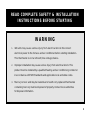
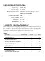
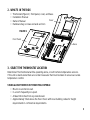
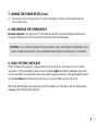
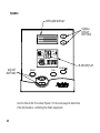
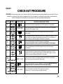
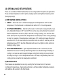
Installation Instructions
MODEL 8870
These instructions are for connecting
the Thermostat to the HVAC equipment.
To connect communication features,
please reference the Communicating Thermostat
System Installation Manual.
INSTALLATION INSTRUCTIONS MANUAL
TABLE OF CONTENTS
Warning . . . . . . . . . . . . . . . . . . . . . . . . . . . . . . . . . . . . . . . . . . . . . . . . . . . . . . . . . . . . . . . . . . . . . . . 1
Model 8870 Thermostat Specifications . . . . . . . . . . . . . . . . . . . . . . . . . . . . . . . . . . . . . . . . . . 2
1. HVAC System Pre-Installation Check List . . . . . . . . . . . . . . . . . . . . . . . . . . . . . . . . . . . . . . . 2
2. What’s In The Box . . . . . . . . . . . . . . . . . . . . . . . . . . . . . . . . . . . . . . . . . . . . . . . . . . . . . . . . . . . 3
3. Select The Thermostat Location . . . . . . . . . . . . . . . . . . . . . . . . . . . . . . . . . . . . . . . . . . . . . . . 3
4. Disassembly . . . . . . . . . . . . . . . . . . . . . . . . . . . . . . . . . . . . . . . . . . . . . . . . . . . . . . . . . . . . . . . . . 4
5. Mount Base To Wall . . . . . . . . . . . . . . . . . . . . . . . . . . . . . . . . . . . . . . . . . . . . . . . . . . . . . . . . . 5
6. Setting The Dip Switches . . . . . . . . . . . . . . . . . . . . . . . . . . . . . . . . . . . . . . . . . . . . . . . . . . . . 6
7. Wiring The Thermostat . . . . . . . . . . . . . . . . . . . . . . . . . . . . . . . . . . . . . . . . . . . . . . . . . 7
8. Reassemble The Thermostat . . . . . . . . . . . . . . . . . . . . . . . . . . . . . . . . . . . . . . . . . . . . . . . . . . 9
9. HVAC System Check Out . . . . . . . . . . . . . . . . . . . . . . . . . . . . . . . . . . . . . . . . . . . . . . . . . . . . . . . 9
10. Optional HVAC Set-Up Features . . . . . . . . . . . . . . . . . . . . . . . . . . . . . . . . . . . . . . . . . . . .12
11. To Access The HVAC Set-Up Features . . . . . . . . . . . . . . . . . . . . . . . . . . . . . . . . . . . . . . . . .13
Wiring Diagrams . . . . . . . . . . . . . . . . . . . . . . . . . . . . . . . . . . . . . . . . . . . . . . . . . . . . . .16 – 22
Note Pages . . . . . . . . . . . . . . . . . . . . . . . . . . . . . . . . . . . . . . . . . . . . . . . . . . . . . . . . . .23 – 25
© Research Products Corporation 2001
READ COMPLETE SAFETY & INSTALLATION
INSTRUCTIONS BEFORE STARTING
WARNING
1. 120-volts may cause serious injury from electrical shock. Disconnect
electrical power to the furnace and air conditioner before starting installation.
This thermostat is not a 120-volt (line voltage) device.
2. Improper installation may cause serious injury from electrical shock. This
product must be installed by a qualified heating and air conditioning contractor
in accordance with NEC Standards and applicable local and state codes.
3. Mercury is toxic and may be hazardous to health. Any replaced thermostats
containing mercury must be disposed of properly. Contact local authorities
for disposal information.
1
MODEL 8870 THERMOSTAT SPECIFICATIONS:
Control Voltage
Switched Voltage
Maximum Operating Current
Maximum Surge Current
Control Accuracy
Control Range
Operating Range
24V AC ±20%
18 – 30V AC
2.0A total at rated voltage, through all outputs.
1.0A through any one output.
2.0A
±1.0°F
40° – 90°F
32° – 99°F
1. HVAC SYSTEM PRE-INSTALLATION CHECK LIST
Before getting started determine what type of heating system is/will be installed in the house.
Then use Table 1 to determine if the proper numbers of wires are available depending on the
HVAC System. Additional wires will be required for communication system.
TABLE 1
APPLICATION
2
# OF HVAC WIRES
DIAGRAM
PAGE #
Single Stage Furnace & AC
5
1
16
Two Stage Furnace & Two Stage AC
7
2
17
Roof Top Unit (Two Stage Heat & Two Stage Cool)
7
3
18
Boiler with AC (Two Transformers)
5
4
19
Single Stage Heat Pump
7
5
20
Two Stage Heat Pump
9
6
21
First Stage Radiant Floor Heat
Second Stage Furnace One Stage of Cooling
6
7
22
2. WHAT’S IN THE BOX
•
•
•
•
Thermostat (Figure 1 ): front panel, cover, and base
Installation Manual
Cover
Owners Manual
Hardware bag: screws and wall anchors
FIGURE 1
Front Panel
Base
3. SELECT THE THERMOSTAT LOCATION
Determine if the thermostat will be operating alone, or with remote temperature sensors.
If the unit is stand-alone there are certain measures that must be taken to ensure accurate
temperature control.
STAND-ALONE THERMOSTAT MOUNTING CRITERIA:
• Mount on an interior wall.
• In a room frequently occupied.
• At least 18 inches from any outside wall.
• Approximately 5 feet above the floor. Check with local building codes for height
requirements in commercial requirements.
3
DO NOT locate the thermostat:
• Behind doors, in corners or other dead air spaces.
• In direct sunlight or near lamps, appliances or other sources of radiant heat.
• On an outside wall or wall exposed to an unconditioned space (i.e. garage, etc.).
• In the flow path of a supply register, in stairways or near outside doors.
• On a wall where concealed pipes and/or ductwork will affect the thermostat.
• Near sources of electrical interference such as arcing relay contacts.
WITH REMOTE TEMPERATURE SENSORS
Follow the guidelines for placement of the sensors and locate the thermostat indoors where
operating range (see specs) will not be violated (i.e. do not install in a cold garage or hot
equipment room). See the sensor installation literature for additional details.
4. DISASSEMBLY
No tools required – use hands to pull the front
panel off of the base (Figure 2 ). While holding
the base of the thermostat, apply pressure to the
base of the latch with your thumb (Figure 3 ).
Both sides have a latch, but it is easiest to
unlatch one side at a time.
FIGURE 2
CAUTION: Loss of internal programs may result from static discharge to thermostat circuit
board. Installer must touch a grounded metal object before handling the circuit board.
4
FIGURE 3
Press
base here
Latch
5. MOUNT BASE TO WALL
There are four screw holes located on the base of the thermostat; two are for a junction box
mounting, along with two for alternate mounting spacing. Use one of the holes on the top
and one on the bottom.
a) Place the base over the wire hole opening in the wall; level the base and mark the screw
hole mounting locations (leveling required for appearance only).
b) If using supplied wall anchors, drill 3/16" hole in the center of the marked locations and
tap in the wall anchors. If using the supplied screws only, drill a 3/32" hole in the center
of the marked locations.
c) Fasten the base to the wall with the supplied screws.
d) Seal wire entry using caulk, drywall putty or insulation.
CAUTION: Minimize wire entry hole size and seal – drafts from
inside the wall could affect temperature readings.
5
FIGURE 4
6. SETTING THE DIP SWITCHES
Set the dip switches located on the thermostat circuit
board (Figure 4) according to the application needs (Table 2 ).
Figure 4 shows what each switch corresponds to depending on position. Switch one should be set in the “OFF Servant” position unless you plan to
broadcast readings from remote temperature sensors to other thermostats in the
system when there is no communication system in place.
6
TABLE 2
APPLICATION
SWITCH #1
SWITCH #2
SWITCH #3
SWITCH #4
Single Stage Furnace & AC
Servant
Fossil
Single
H/C
Two Stage Furnace & Two Stage AC
Servant
Fossil
Multi
H/C
Roof Top Unit (Two Stage Heat & Two Stage Cool)
Servant
Fossil
Multi
H/C
Boiler with AC (Two Transformers)
Servant
Fossil
Single
H/C
Single Stage Heat Pump
Servant
Electric
Single
HT. Pump
Two Multi-stage Heat Pump
Servant
Electric
Multi
HT. Pump
First Stage Radiant Floor Heat
Second Stage Furnace One Stage of Cooling
Servant
Fossil
Multi
H/C
7. WIRING THE THERMOSTAT
a) Strip 1/4" of insulation from each wire to be used. Figure 5 shows all wiring
terminal definitions.
b) Secure wires into the terminals on the base according to the appropriate wiring diagram
(Table 3 ). Use color-coding practices (i.e. white wire to W terminal) whenever possible.
TABLE 3
APPLICATION
DIAGRAM
PAGE #
Single Stage Furnace & AC
1
16
Two Stage Furnace & Two Stage AC
2
17
Roof Top Unit (Two Stage Heat & Two Stage Cool)
3
18
Boiler with AC (Two Transformers)
4
19
Single Stage Heat Pump
5
20
Two Stage Heat Pump
6
21
First Stage Radiant Floor Heat
Second Stage Furnace One Stage of Cooling
7
22
7
FIGURE 5
8
7. WIRING THE THERMOSTAT (Cont.)
c)
Check each wire to ensure it is securely fastened, not broken, and exposed wires
are not touching.
8. REASSEMBLE THE THERMOSTAT
No tools required – line up pins on circuit board with the corresponding terminal blocks.
Use your hands to push the front panel securely to the mounted base.
CAUTION: Loss of internal programs may result from static discharge to thermostat circuit
board. Installer must touch a grounded metal object before handling the circuit board.
9. HVAC SYSTEM CHECK OUT
HVAC installer may need to connect 24V AC to the R and C terminals to check HVAC
operation. If the automation system is to be installed after the HVAC installation, leave the
R and C terminals connected to ensure the HVAC system operates. If the automation system
is installed before the HVAC wiring, then do not connect HVAC wires to R and C.
When the thermostat is first turned on all of the graphics of the main LCD are momentarily
displayed; this will look like Figure 6.
9
FIGURE 6
MESSAGE DISPLAY
SCROLL/
SET-UP
BUTTONS
DIF1
DIF2
BIAS
ROOM
F
FAN
C
ON
RH
HUMIDIFY
DEHUM
NETWORK
OVERRIDE
F
C
REMOTE
ADJUST
BUTTONS
Mode
O
R
EM. HEAT-AUX
COOL
Fan
Enter
MAIN DISPLAY
Use the Check Out Procedure (Figure 7, on the next page) to determine
if the thermostat is controlling the HVAC equipment.
10
FIGURE 7
CHECK-OUT PROCEDURE
CAUTION: The following check-out procedure will turn the heating and cooling equipment on and off. Do not
operate in cooling at low outdoor temperatures. Do not operate in heating at high outdoor temperatures.
Refer to equipment manufacturer specifications for safe operating temperatures.
STEP PRESS
1
MODE
2
FAN
3
MODE
FAN ON
COOL
COOL
5
MODE
6
MODE
>
HEAT
7A
HEAT -AUX
HEAT PUMP ONLY
8
MODE
9
MODE
Press the Fan button. System blower should start and FAN ON appears
on display. Press again to stop.
Press the Mode button until COOL appears along with the current
cool setting.
Use the down arrow to lower the set point 3°F below room temp. In 5-10
seconds the first stage of cooling begins and the COOL icon begins to
flash. If there is a second stage it will begin in 4 minutes.
Press the Mode button until OFF appears on the display.
You must change the mode to override the Minimum On time delays.
HEAT
7
NOTES AND REACTION
Press the Mode button repeatedly untill OFF appears on the display.
>
4
LOOK FOR...
Press the Mode button until HEAT appears along with the current
heat setting.
Use the up arrow to raise the set point 3°F above room temp. In 5-10
seconds the first stage of heating begins and the HEAT begins to flash.
If there is a second stage it will begin in 4 minutes.
"-AUX" comes on when the auxiliary heat terminal (W1) is energized.
The LED on top of thermostat will illuminate.
Press the Mode button until OFF appears on the display. During Check-out,
change the mode to override the Minimum On time delays.
EM. HEAT
Press Mode button until EM. HEAT appears on display.
Repeat step 7 to verify Emergency Heat operation.
HEAT PUMP ONLY
11
10. OPTIONAL HVAC SET-UP FEATURES
There are a number of HVAC features that can be configured for the particular application.
These include temperature control options, display options and high/low balance points
(heat pumps only).
A) TEMPERATURE CONTROL OPTIONS
1. OFFSET – allows the user to offset the displayed room temperature ±3°F from true
temperature. This thermostat is calibrated to be within ±1°F of true temperature.
2. 1ST STAGE DIFFERENTIAL – determines the level of control and consequently the cycle
rate. Adjustable between 0.5°F and 2.0°F, this is the value above/below the set point
that the temperature must rise (fall) to start the cooling (heating). It is also the value
below (above) the set point that the temperature must fall (rise) for the cooling (heating)
to stop. For example, if the temperature setting was 70°F and the 1st stage differential
was set at 0.5°F, in the heat mode the heat would come on at 69.5°F and stay until the
temperature was 70.5°F. A small differential will result in a tighter control, but more
heating/cooling cycles.
3. 2ND STAGE DIFFERENTIAL – again adjustable between 0.5°F and 2.0°F, this also
determines the level of control by determining when to use the 2nd stage of heating or
cooling. It can also be used to keep 2nd stage cooling from coming on too soon when
1st stage is acting to control temperature levels or to keep costly auxiliary heat from
coming on too soon when the heat pump is sufficient.
B) BALANCE POINTS
These values are adjustable, but are only used by the thermostat when it has been
configured to operate as a heat pump and when a remote outdoor temperature sensor,
with address #1, is wired to the thermostat.
12
B) BALANCE POINTS (Cont.)
1. LOW BALANCE POINT – the outdoor temperature below which compressor terminals
will not be energized.
2. HIGH BALANCE POINT – the outdoor temperature above which the auxiliary heat terminal
will not be energized in the HEAT mode (does not effect Emergency Heat operation).
C) DISPLAY OPTIONS
1. TEMPERATURE SCALE – all temperatures displayed including room temperatures and
set points can be °F or °C.
2. SHOW TEMPERATURE SET POINTS ALWAYS – keeps the temperature settings visible on
the display at all times.
3. SHOW TEMPERATURE SET POINTS ONLY IF CHANGED – displays the temperature
settings (heat and/or cool) only when the user changes them. The first press of either
the up or down adjust buttons will display the settings.
4. SHOW DATE AND TIME – the message display will, by default, scroll three messages
showing the status of the mode, fan and equipment outputs. A fourth date and time can be
added to this list. However, the automation system must transmit the time and date to
the thermostat at least once a day. If the automation system is not capable of doing
this, the date and time can be configured not to show.
11. TO ACCESS THESE HVAC SET-UP FEATURES
When first powered up, the message display will scroll through the current mode status,
fan status, and heating/cooling output status. This is referred to as Passive Display because
you do not interact with it. To get into the Set-Up Menu, press the Enter button
and Mode button at the same time. This is referred to as User Interactive Display, as the user
navigates through various menu and sub-menu selections to change variables.
13
11. TO ACCESS THESE HVAC
SET-UP FEATURES (Cont.)
Set-Up is menu driven but only one menu
item is visible at a time. Figure 8 shows
the entire Main Menu. Selecting any one
of the Main Menu items (by pressing the
Enter button) will enter a corresponding
Sub-Menu. Figure 8 also shows the
Temperature Set-Up, Balance Points
Set-Up and Display Set-Up sub-menus
expanded. The Scroll Up
and Scroll
Down
buttons are used to move
between menu items or change values.
The Enter
button is used to select
a menu item or enter a value. When in
Thermostat Set-Up, if none of the three
navigation buttons are pressed in 5 minutes, the display will return to Passive
Display. Again, you will only see one
menu item at a time.
14
FIGURE 8
FIGURE 8 (Cont.)
15
DIAGRAM 1 – SINGLE STAGE FURNACE AND AC
APRILAIRE MODEL
8870 THERMOSTAT
ONE-STAGE FURNACE
C
L1
R
24
VAC
RC
RH
C
FAN
RELAY
G
1ST
STAGE
HEAT
1ST STAGE
COOL
O
W1
G
Y1
W1
Y1
ONE-STAGE AIR
CONDITIONER
1ST
STG
COOL
W2
Y2
RSR
REMOTE
SENSOR(S)
R
RSC
RSB
RSA
BB+
AA+
B
Y1
C
IMPORTANT!
NOTE: HVAC installer may need to connect 24V AC
to the R and C terminals to check the HVAC operation.
If the automation system is to be installed after the
HVAC installation, leave the R and C terminals connected
to ensure the HVAC system operates. If the automation
system is installed before the HVAC wiring, then DO NOT
connect HVAC wires to R and C.
The B terminal is for
reversing valve-heat.
DO NOT connect the
B terminal to
common side of
transformer.
24V FIELD WIRING
FACTORY WIRING
OPTIONAL 24V
FIELD WIRING (SEE NOTE)
16
SEE
NOTE
REF
COMMUNICATION
TERMINALS
L2
120
VAC
DIAGRAM 2 – TWO STAGE FURNACE AND TWO STAGE AC
APRILAIRE MODEL
8870 THERMOSTAT
TWO-STAGE FURNACE
R
C
FAN
RELAY
G
O
1ST
STAGE
HEAT
1ST STAGE
COOL
1ST
STG
COOL
G
Y1
W1
Y1
W2
2ND STAGE
COOL
TWO-STAGE AIR
CONDITIONER
2ND
STG
COOL
W1
Y2
Y1
C
Y2
W2
Y2
RSR
REMOTE
SENSOR(S)
RC
RH
RSC
RSB
RSA
REF
COMMUNICATION
TERMINALS
R
24
VAC
2ND
STAGE
HEAT
SEE
NOTE
C
L1
L2
120
VAC
BB+
AA+
B
IMPORTANT!
The B terminal is for
reversing valve-heat.
DO NOT connect the
B terminal to
common side of
transformer.
NOTE: HVAC installer may need to connect
24V AC to the R and C terminals to check the
HVAC operation. If the automation system is
to be installed after the HVAC installation,
leave the R and C terminals connected to ensure
the HVAC system operates. If the automation
system is installed before the HVAC wiring,
then DO NOT connect HVAC wires to R and C.
24V FIELD WIRING
FACTORY WIRING
OPTIONAL 24V
FIELD WIRING (SEE NOTE)
17
DIAGRAM 3 – ROOF TOP UNIT (TWO STAGE HEAT AND TWO STAGE COOL)
ROOF TOP UNIT
APRILAIRE MODEL
8870 THERMOSTAT
C
L1
24
VAC
C
FAN
RELAY
G
O
1ST
STAGE
HEAT
W1
1ST
STG
COOL
2ND
STAGE
HEAT
G
W1
Y1
Y1
W2
Y2
RSR
RSC
RSB
RSA
REF
BB+
AA+
IMPORTANT!
The B terminal is for
reversing valve-heat.
DO NOT connect the
B terminal to common
side of transformer.
B
W2
2ND
STG
COOL
Y2
24V FIELD WIRING
FACTORY WIRING
OPTIONAL 24V
FIELD WIRING (SEE NOTE)
18
SEE
NOTE
R
RC
RH
REMOTE
SENSOR(S)
R
COMMUNICATION
TERMINALS
L2
120
VAC
NOTE: HVAC installer may need to connect
24V AC to the R and C terminals to check
the HVAC operation. If the automation
system is to be installed after the HVAC
installation, leave the R and C terminals
connected to ensure the HVAC system
operates. If the automation system is
installed before the HVAC wiring, then
DO NOT connect HVAC wires to R and C.
DIAGRAM 4 – BOILER WITH AC (TWO TRANSFORMERS)
APRILAIRE MODEL
8870 THERMOSTAT
AIR HANDLER
C
R
L1
RC
RH
24
VAC
RSR
REMOTE
SENSOR(S)
R
C
1ST STAGE
COOL
G
O
Y1
G
W1
Y1
AIR CONDITIONER
1ST
STG
COOL
W2
Y2
Y1
B
1ST
STG
HEAT
W1
24V FIELD WIRING
FACTORY WIRING
OPTIONAL 24V
FIELD WIRING (SEE NOTE)
C
24
VAC
R
L1
The thermostat B
terminal is for reversing
valve-heat. DO NOT
connect the B terminal
to common side of
transformer.
BB+
AA+
BOILER
C
IMPORTANT!
SEE
NOTE
REF
COMMUNICATION
TERMINALS
FAN
RELAY
RSC
RSB
RSA
120
VAC
L2
L2
120
VAC
NOTE: HVAC installer may need to connect
24V AC to the R and C terminals to check the
HVAC operation. If the Automation system
is to be installed after the HVAC installation,
leave the R and C terminals connected to
ensure the HVAC system operates. If the
automation system is installed before the
HVAC wiring, then DO NOT connect HVAC
wires to R and C.
19
DIAGRAM 5 – SINGLE STAGE HEAT PUMP
APRILAIRE MODEL
8870 THERMOSTAT
C
R
RC
RSR
RH
RSC
RSB
RSA
INDOOR HEAT PUMP UNIT
L1
24
VAC
REMOTE
SENSOR(S)
R
C
FAN
RELAY
G
AUX
HEAT
COMPRESSOR
G
W1
W1
Y1
Y1
B
Y1
1ST
STG
COMP.
B
O
W1
REV
VALVE
COOL
REV
VALVE
HEAT
OUTDOOR HEAT PUMP UNIT
24V FIELD WIRING
FACTORY WIRING
20
BB+
AA+
IMPORTANT!
DEFROST
C
W2
Y2
NOTE: HVAC installer may
need to connect 24V AC
to the R and C terminals to
check the HVAC operation.
If the automation system
is to be installed after the
HVAC installation, leave
the R and C terminals
connected to ensure the
HVAC system operates. If
the automation system is
installed before the HVAC
wiring, then DO NOT connect
HVAC wires to R and C.
SEE
NOTE
REF
O
COMMUNICATION
TERMINALS
L2
120
VAC
OPTIONAL 24V
FIELD WIRING (SEE NOTE)
The thermostat B
terminal is for
reversing valve-heat.
DO NOT connect the
B terminal to common
side of transformer.
DIAGRAM 6 – TWO STAGE HEAT PUMP
APRILAIRE MODEL
8870 THERMOSTAT
C
INDOOR HEAT PUMP UNIT
R
C
FAN
RELAY
1ST
STAGE
HEAT
1ST STAGE
COMPRESSOR
G
W1
W1
Y1
Y1
W2
Y2
W2
SEE
NOTE
REF
BB+
AA+
B
B
Y2
Y1
C
NOTE: HVAC installer may
need to connect 24V AC
to the R and C terminals to
check the HVAC operation.
If the automation system
is to be installed after the
HVAC installation, leave
the R and C terminals
connected to ensure the
HVAC system operates. If
the automation system is
installed before the HVAC
wiring, then DO NOT connect
HVAC wires to R and C.
O
Y2
W1
2ND STAGE
COMPRESSOR
DEFROST
2ND
STAGE
HEAT
O
G
RSR
RSC
RSB
RSA
COMMUNICATION
TERMINALS
24
VAC
REMOTE
SENSOR(S)
R
RC
RH
L1
L2
120
VAC
2ND
STG
COMP.
REV
VALVE
COOL
1ST
STG
COMP.
REV
VALVE
HEAT
IMPORTANT!
The thermostat B
terminal is for
reversing valve-heat.
DO NOT connect the
B terminal to common
side of transformer.
OUTDOOR HEAT PUMP UNIT
24V FIELD WIRING
FACTORY WIRING
OPTIONAL 24V
FIELD WIRING (SEE NOTE)
21
DIAGRAM 7 – FIRST STAGE RADIANT FLOOR HEAT
SECOND STAGE FURNACE ONE STAGE OF COOLING
APRILAIRE MODEL
8870 THERMOSTAT
ONE STAGE FURNACE
C
L1
R
24
VAC
C
FAN
RELAY
REMOTE
SENSOR(S)
R
RC
RH
RSR
RSC
RSB
RSA
SEE
NOTE
G
W1
G
W1
Y1
Y1
1ST STAGE
COOL
COOLING EQUIPMENT
1ST
STG
COOL
REF
O
1ST
STAGE
HEAT
Aprilaire Model 8024
24-volt Relay Pack
BB+
AA+
B
(not supplied)
Y1
C
W2
Y2
COMMUNICATION
TERMINALS
L2
120
VAC
24V
COM
1 W
IMPORTANT!
2
RADIANT FLOOR HEAT
1ST
STAGE
HEAT
E/W2
W
5
Y
C
24
VAC
3 R
4
6
7 Y
R
The thermostat B
terminal is for reversing
valve-heat. DO NOT
connect the B terminal
to common side of
transformer.
120
VAC
O
L1
L2
8
9
24V FIELD WIRING
FACTORY WIRING
OPTIONAL 24V
FIELD WIRING (SEE NOTE)
22
NOTE: HVAC installer may need to connect 24V AC to the R and C
terminals to check the HVAC operation. If the Automation system
is to be installed after the HVAC installation, leave the R and C
terminals connected to ensure the HVAC system operates. If the
automation system is installed before the HVAC wiring, then
DO NOT connect HVAC wires to R and C.
NOTES:
23
NOTES:
24
NOTES:
25
®
THE BEST IN INDOOR AIR COMFORT
The Aprilaire® Indoor Air Comfort System is an integrated group of air quality enhancement products
designed to work with heating and cooling systems to make homes more comfortable. For the best in indoor
air quality, install Aprilaire brand products, to solve your customers’ Indoor Air Comfort needs.
Aprilaire®
Automatic Humidifiers
Aprilaire®
High Efficiency Air Cleaners
Aprilaire®
Energy Recovery Ventilators
The world’s first computer-equipped,
completely automatic humidifiers.
Delivers the cleanest,
healthiest air ever available from
a whole-house air cleaner.
Your best value for a constant,
controlled supply of fresh air with
energy-recovery.
Aprilaire®
Zone Control Systems
Aprilaire®
Electronic Thermostats
The most reliable way to
achieve temperature control in
every area of your home.
Ultra-thin, easy-to-use digital,
programmable, and communicating controls
featuring pinpoint accuracy.
P.O. BOX 1467 • MADISON, WI 53701-1467
B2202660 REV. 011/01