1
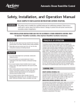
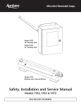
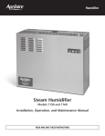
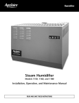
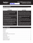
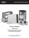
Operating Instructions
R E A D A N D S AV E T H E S E I N S T R U C T I O N S
Aprilaire Communicating Thermostat
®
Model 8870
CAUTION: Do not set to OFF mode during periods when
freezing temperatures could occur.
Thank you for your recent purchase of an Aprilaire® Communicating Thermostat. With this
purchase, you have invested in the highest quality thermostat currently available.
This Model 8870 Communicating Thermostat operates similarly to a conventional thermostat but
has the unique capability of being controlled, either locally or remotely (from a home automation
system). The Model 8870 thermostat is capable of integration into your home automation system
or independently operated with the Aprilaire Model 8825 System Controller.
Note: This manual covers basic operation of the thermostat,
which may be altered by the home automation system setup.
GETTING FAMILIAR WITH THE APRILAIRE THERMOSTAT (refer to Figure 1 )
OPERATING INSTRUCTIONS – OWNERS MANUAL
TABLE OF CONTENTS
Getting Familiar With The Aprilaire Thermostat . . . . . . . . . . . . . . . . . . . . . . . . . . . . . . . . . . . . . . . 1
Operating The Thermostat . . . . . . . . . . . . . . . . . . . . . . . . . . . . . . . . . . . . . . . . . . . . . . . . . . . . . . 4
MESSAGE DISPLAY – Two types of messages are displayed; permanent and temporary.
Permanent messages scroll continually. This includes the three default status messages
(i.e., mode status, fan status, equipment status) and optional four personal messages
that can be added through the home automation programming or HyperTerminal session.
Temporary (flashing) messages are programmed the same as personal messages but are
designed to be quick messages that get reset shortly after they are displayed.
1. Select The Mode . . . . . . . . . . . . . . . . . . . . . . . . . . . . . . . . . . . . . . . . . . . . . . . . . . . . . . . . . . . . . . . 4
MESSAGE DISPLAY
2. Setting Temperatures . . . . . . . . . . . . . . . . . . . . . . . . . . . . . . . . . . . . . . . . . . . . . . . . . . . . . . . . . . . 6
SCROLL/
SET-UP
BUTTONS
3. Fan Operation . . . . . . . . . . . . . . . . . . . . . . . . . . . . . . . . . . . . . . . . . . . . . . . . . . . . . . . . . . . . . . . . . . . 6
4. Backlight Operation . . . . . . . . . . . . . . . . . . . . . . . . . . . . . . . . . . . . . . . . . . . . . . . . . . . . . . . . . . . . . . . 6
5. Network Override . . . . . . . . . . . . . . . . . . . . . . . . . . . . . . . . . . . . . . . . . . . . . . . . . . . . . . . . . . . . . . 7
DIF1
DIF2
BIAS
6. Clearing A Temporary Flashing Message . . . . . . . . . . . . . . . . . . . . . . . . . . . . . . . . . . . . . . . . . 7
NETWORK
OVERRIDE
Thermostat Set-Up . . . . . . . . . . . . . . . . . . . . . . . . . . . . . . . . . . . . . . . . . . . . . . . . . . . . . . . . . . . . . . . . 7
F
C
REMOTE
In Case Of Power Failure . . . . . . . . . . . . . . . . . . . . . . . . . . . . . . . . . . . . . . . . . . . . . . . . . . . . .13
Cleaning . . . . . . . . . . . . . . . . . . . . . . . . . . . . . . . . . . . . . . . . . . . . . . . . . . . . . . . . . . . . . . . . . . . . .13
ROOM
F
FAN
C
ON
RH
HUMIDIFY
DEHUM
ADJUST
BUTTONS
Mode
O
R
EM. HEAT -AUX
COOL
Fan
Enter
MAIN DISPLAY
Notes . . . . . . . . . . . . . . . . . . . . . . . . . . . . . . . . . . . . . . . . . . . . . . . . . . . . . . . . . . . . . . . . . . . .14 –16
Warranty . . . . . . . . . . . . . . . . . . . . . . . . . . . . . . . . . . . . . . . . . . . . . . . . . . . . . . . . . . . . . . . . . . .17
© Research Products Corporation 2006
1
SCROLL/SET-UP BUTTONS – The Scroll/Set-Up buttons function with the set-up features of
the thermostat (refer to page 7).
FIGURE 2
NETWORK STATUS
ROOM TEMPERATURE/
RELATIVE HUMIDITY
MODE BUTTON – Five modes of operation are available on the Model 8870 thermostat:
OFF, COOL, HEAT or COOL, EM. HEAT (for heat pumps only), and HEAT. The mode of
operation indicates how you want your heating and cooling equipment to operate.
ADJUST BUTTON – The Adjust buttons adjust the heating and cooling
temperature settings.
LOCKOUT
FAN STATUS
NETWORK
OVERRIDE
FAN BUTTON – The fan can be operated continuously (FAN ON) or only when there is a
need to heat or cool.
ENTER (NETWORK OVERRIDE) BUTTON – The Enter button is used to override the home
automation system, to clear temporary flashing messages on the message display, and edit
the set-up features of the thermostat.
SET POINTS
REMOTE TEMPERATURE/
RELATIVE HUMIDITY
MODE STATUS
MAIN DISPLAY – The MAIN DISPLAY (see Figure 2 ) provides the mode status, temperature
and system status information.
MAIN DISPLAY (Cont.)
• MODE STATUS – Shows the current mode of operation: OFF, COOL, HEAT or COOL,
EM. HEAT (for heat pumps only), and HEAT. The current mode will flash to show when
the equipment is running.
• REMOTE TEMPERATURE/RELATIVE HUMIDITY – A temperature and/or a relative
humidity value will be displayed alternately here when an optional remote temperature
and/or humidity sensor has been installed (typical use is for outdoor temperature).
• SET POINTS – Shows the Heating and/or Cooling temperature settings.
• NETWORK OVERRIDE – When NETWORK OVERRIDE is displayed, the thermostat has
been taken off-line from the automation system. The thermostat can then only be operated
at the thermostat.
• FAN STATUS – FAN ON indicates the fan is set to operate continuously.
• LOCKOUT – The lockout setting shows the thermostat buttons have been locked out
and the thermostat settings can not be changed at the thermostat.
• ROOM TEMPERATURE – Shows the current room temperature. The temperature can
be displayed in °F or °C. This would show relative humidity (%) if the thermostat has
been installed with an optional humidity control senor.
2
• NETWORK STATUS – This computer icon shows the thermostat is connected to the
system. The icon will flash when the thermostat sends or receives information. If there
is no activity on the system for 15 minutes the computer icon will be steadily displayed with
a cross-out circle. This does not mean the thermostat is unable to communicate, only
that there has been no communication to this thermostat in the past 15 minutes.
3
OPERATING THE THERMOSTAT
1. SELECT THE MODE (cont.)
Notes on temperature adjustments:
• HEAT OR COOL (AUTO-CHANGEOVER) – HEAT or COOL appears on the display. Either
the heating or cooling equipment will operate to maintain the room temperature at or
above the HEAT setting and at or below the COOL setting. HEAT or COOL will flash when
the respective equipment is operating.
• The COOL setting must always be a minimum of 2° (F or C) higher than the HEAT setting.
The thermostat will automatically maintain the 2° difference. For example, if the Cooling
set point is 75°F and one changes the Heating set point to 74°F, the thermostat will
automatically change the Cooling set point to 76°F.
• The lockout
icon will appear on the display when attempting to make a change, if the
thermostat has been configured to be locked out or the desired change violates the thermostat limits (i.e. lowest allowable HEAT setting is 40°F, highest allowable COOL setting is
90°F, etc.). Lockout configuration can be altered in set-up menu (see page 10 ).
1. SELECT THE MODE
The thermostat can be set to OFF, COOL, HEAT or COOL (AUTO-CHANGEOVER), EM. HEAT (for
heat pumps only), and HEAT modes. To set, press the MODE button until the desired mode
appears on the display (see Figure 3 ).
• OFF – Select the OFF mode to prevent the heating and cooling equipment from operating.
CAUTION: Do not set to OFF mode during periods when
freezing temperatures could occur.
• COOL – COOL appears on the display and only the cooling equipment will be operated
to maintain the temperature at the COOL setting. COOL will flash on the main display
when the cooling equipment is operating.
4
• EMERGENCY HEAT (EM. HEAT
for heat pump equipment only) –
EM. HEAT appears on the display
and only the back-up heat source
will be operated to maintain the
room temperature above the
HEAT setting. This is generally
more expensive than using the
heat pump (HEAT MODE), so
use accordingly. Typical usage
is when the heat pump has
malfunctioned.
FIGURE 3
COOL
OFF
O
R
HEAT
• HEAT – HEAT appears on the
display and only the heating
equipment will be operated to
maintain the temperature at the
HEAT setting. HEAT will flash
on the main display when the
heating equipment is operating.
EM. HEAT
COOL
HEAT OR COOL
EM. HEAT
HEAT
HEAT
5
2. SETTING TEMPERATURES
5. NETWORK OVERRIDE
Press the Up or Down adjust button. The setting to be changed will begin to flash. Press and
hold the button to change the setting.
If the Network Override has not been disabled in the Thermostat Set-Up, the Network Override
can be initiated by pressing the Enter
button. When initiated, the thermostat is taken offline from the automation system. The thermostat can then only be operated at the thermostat.
Pressing the Enter button again will restore network communication.
If operating in the HEAT mode, the only temperature set point available to change is the Heat
setting. When the room temperature drops below this setting the heat will come on (call for
heating) to raise the temperature. EM. HEAT mode uses the HEAT setting.
If operating in the COOL mode, the only temperature set point available to change is the
COOL setting. When the room temperature rises above this setting the Cooling will come on
(call for cooling) to lower the temperature.
If operating in the HEAT or COOL mode the first press of the Up or Down adjust button will
indicate which of the two temperature settings will be adjusted – it will be the one flashing.
If this is not the desired temperature to adjust, press the Mode button to access the other
temperature setting.
Custom Home Automation systems have the ability to send a temporary message to the
message display. This message will flash until the user acknowledges the message. To
acknowledge message press the Enter
button.
THERMOSTAT SET-UP
3. FAN OPERATION
The thermostat has many features that can be adjusted to customize operations.
Temperature Control Set-Up, Balance Point Set-Up and Communications Set-Up, in
particular, should only be adjusted with the help of a qualified service technician.
The thermostat can operate the fan either continually (FAN ON), or only during Heating and
Cooling calls. Press the Fan button to toggle between these two options. FAN ON is
recommended for media/electronic air cleaners, ventilating equipment, and to allow for
humidification in mild climates.
TO ACCESS THESE FEATURES – When first powered up, the Message Display will scroll
through the current mode status, fan status, and Heating/Cooling output status. This is
referred to as Passive Display because you do not interact with it. To get into the set-up
menu, press the ENTER button and MODE button at the same time.
4. BACKLIGHT OPERATION
Thermostat Set-Up is menu driven but only one menu item is visible at a time. Figure 4
shows the entire Main Menu. Selecting any one of the Main Menu items (by pressing the
Enter button) will enter a corresponding Sub-Menu. The Scroll Up and Scroll Down buttons
are used to move between menu items or change adjustable values. The Enter button is
used to select a menu item or enter a value. When in Thermostat Set-Up, if none of the
Operation of the backlight is configured in the Thermostat Set-Up. Depending on the set-up,
the backlight will light at the press of any button, or it can be disabled (refer to page 11).
The backlight will stay on for 10 seconds after the last press of a button.
6
6. CLEARING A TEMPORARY FLASHING MESSAGE
7
three navigation buttons are pressed in 5
minutes, the display will return to Passive
Display. Again, one menu item can be
seen at a time.
FIGURE 5
THE FOLLOWING ITEMS
ARE CONFIGURABLE IN
THERMOSTAT SET-UP:
FIGURE 4
8
• NETWORK OVERRIDE SET-UP –
This enables or disables the Network
Override feature. When Network
Override has been invoked the thermostat will only respond to the buttons
of the thermostat; commands sent by
the automation system are ignored.
Pressing the Enter button activates
Network Override. However, you can
disable this feature if you don’t want
users to be able to activate Network
Override. Enabling and Disabling
of this feature is done through
Thermostat Set-Up (see Figure 5 ).
FIGURE 6
9
• THERMOSTAT BUTTON LOCKOUT – This feature disables the buttons of the thermostat
completely, or to a limited degree. For example, the MODE and FAN status can be set
and then locked, so the buttons will not allow those settings to be changed. Additionally,
this can be set to allow changes for a limited time and amount of change. For example,
you can limit temperature changes to ±3°, if desired (see Figure 6 ).
• COMMUNICATIONS SET-UP – This is where the thermostat address is entered.
Additionally, the total number of thermostats is entered here to optimize communication
timing. This thermostat also has the ability to communicate at a baud rate of 19200, which
can be selected in Communications Set-Up. Consult a qualified service technician before
changing any of the values in this Sub-Menu (Sub-Menu not shown).
• SECURITY SET-UP – This prevents unauthorized individuals from accessing Thermostat
Set-Up. A code can be setup that must be entered to gain entry into Thermostat Set-Up.
Master key pass word is 7777 (see Figures 7 and 8 ).
• TEMPERATURE SET-UP – The first and second stage differentials can be changed, as can
the display temperature offset. The differentials set the tightness of the temperature control.
If the equipment is operating too often, or the
FIGURE 9
temperature swings are uncomfortably large,
the differentials can be increased or decreased
respectively. The temperature offset (calibration)
allows the user to “customize” the temperature
shown on the display. Consult a qualified service
technician before changing any of the values in
this Sub-Menu (Sub-Menu not shown).
FIGURE 7
FIGURE 8
• BACKLIGHTING SET-UP – Both displays have
backlighting which can be controlled in three
ways (see Figure 9 ). First, backlighting can be
turned on every time a button is pushed. Second,
it can be configured to come on with a button
push, but only when the ambient light is below
a preset value. When “only when needed” is
selected, the user can select from two levels of
ambient light. Finally, it can be disabled.
10
11
• BALANCE POINT SET-UP – Balance points limit heat pump operation when the outdoor
temperature is too high or too low. It requires an optional support module with an
outdoor temperature sensor. Consult a qualified service technician before changing
any of the values in this Sub-Menu (Sub-Menu not shown).
• DISPLAY SET-UP – Here the temperature scale can be changed to °C or °F, and the
temperature settings can be setup to always display or only when being changed
(see Figure 10 ). The message display, when not being used for Thermostat Set-Up
will, by default, scroll through three messages showing the status of the mode, fan, and
equipment output, a fourth date and time
FIGURE 10
can be added to this list. The date and time
must be sent daily to the thermostat from
the automation system to maintain the
accurate time. If this programming cannot
be done, it is best to not have the time
and date displayed.
12
IN CASE OF POWER FAILURE
This thermostat does not require a battery. If the power goes out, the screen is blank.
During the period the power is off, the heating/cooling system will not operate. When
power is restored, the thermostat will return to the previous settings.
The thermostat is equipped with a continuous memory feature which does not require
a battery.
CLEANING
If the surface of the thermostat becomes dirty it can be cleaned with plain water or
with a non-abrasive household cleaner, including glass cleaner. When using any
cleaner be careful not to get any into the interior of the thermostat. Do not spray any
liquid directly onto the thermostat. Spray the cleaner onto a soft cloth and wipe the
surface of the thermostat.
13
NOTES:
14
NOTES:
15
NOTES:
WARRANTY
ELECTRONIC THERMOSTAT FIVE YEAR LIMITED WARRANTY
Your Research Products Corporation Aprilaire® Thermostat unit is expressly warranted for five (5) years from date
of installation to be free from defects in materials and workmanship.
Research Products Corporation’s exclusive obligation under this warranty shall be to supply, without charge, a
replacement for any thermostat which is found to be defective within such five (5) year period and which is
returned, together with the date of installation, no later than thirty (30) days after said five (5) year period by you
to either your original supplier or to Research Products Corporation, Madison, Wisconsin 53701.
THIS WARRANTY SHALL NOT OBLIGATE RESEARCH PRODUCTS CORPORATION FOR ANY LABOR COSTS AND
SHALL NOT APPLY TO DEFECTS IN WORKMANSHIP OR MATERIALS FURNISHED BY YOUR INSTALLER AS
CONTRASTED TO DEFECTS IN THE THERMOSTAT ITSELF.
IMPLIED WARRANTIES OF MERCHANTABILITY OF FITNESS FOR A PARTICULAR PURPOSE SHALL BE LIMITED IN
DURATION TO THE AFORESAID FIVE (5) YEAR PERIOD. RESEARCH PRODUCTS CORPORATION’S LIABILITY FOR
INCIDENTAL OR CONSEQUENTIAL DAMAGES, OTHER THAN DAMAGES FOR PERSONAL INJURIES, RESULTING
FROM ANY BREACH OF THE AFORESAID IMPLIED WARRANTIES OR THE ABOVE LIMITED WARRANTY IS
EXPRESSLY EXCLUDED. THIS LIMITED WARRANTY IS VOID IF DEFECT(S) RESULT FROM FAILURE TO HAVE THIS
THERMOSTAT INSTALLED BY A QUALIFIED HEATING AND AIR CONDITIONING CONTRACTOR. IF THE LIMITED
WARRANTY IS VOID DUE TO FAILURE TO USE A QUALIFIED CONTRACTOR, ALL DISCLAIMERS OF IMPLIED
WARRANTIES SHALL BE EFFECTIVE UPON INSTALLATION.
Some states do not allow limitations on how long an implied warranty lasts or the exclusion or limitation of
incidental or consequential damages, so the above exclusion of limitations may not apply to you.
This warranty gives you specific legal rights and you may also have other rights which vary from state to state.
16
17
®
FRESH IDEAS FOR INDOOR AIR
The Aprilaire® Indoor Air Comfort System is an integrated group of air quality enhancement
products designed to work with your heating and cooling systems to make your home more comfortable.
For the best in indoor air quality, ask your heating and cooling contractor about these fine Aprilaire
products, or visit us at www.aprilaire.com to solve your Indoor Air Comfort needs.
Aprilaire®
Automatic Humidifiers
Aprilaire®
High Efficiency Air Cleaners
Aprilaire®
Energy Recovery Ventilators
The world’s first computer-equipped,
completely automatic humidifiers.
Delivers the cleanest,
healthiest air ever available from
a whole-house air cleaner.
Your best value for a constant,
controlled supply of fresh air with
energy-recovery.
Aprilaire®
Zoned Comfort Control
Aprilaire®
Electronic Thermostats
The most reliable way to
achieve temperature control in
every area of your home.
Ultra-thin, easy-to-use digital,
programmable, and communicating controls
featuring pinpoint accuracy.
RESEARCH PRODUCTS CORPORATION
P.O. BOX 1467 • MADISON, WI 53701-1467 • PHONE: 888/782-8638 • FAX: 608/257-4357 • www.aprilairecontractor.com
61000491 12.06
B2202659B