1
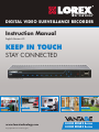
DIGITAL VIDEO SURVEILLANCE RECORDER
Instruction Manual
English Version 4.0
KEEP IN TOUCH
STAY CONNECTED
*8 Channel Model Shown
RETAIL
INDUSTRY
www.lorextechnology.com
Copyright © 2012 Lorex Technology Inc.
BUSINESS
HOME
OUTDOOR
LH330 EDGE2 Series
LH340 EDGE3 Series
Thank you for purchasing the Edge Series Digital Video Surveillance Recorder.
This manual refers to the following models:
• LH338 (8-channel EDGE2)
• LH336 (16-channel EDGE2)
• LH348 (8-channel EDGE3)
• LH346 (16-channel EDGE3)
For the latest online manual, downloads and product updates, and to learn about our
complete range of accessory products, please visit our website at:
www.lorextechnology.com
CAUTION
RISK OF ELECTRIC SHOCK
DO NOT OPEN
CAUTION: TO REDUCE THE RICK OF ELECTRIC SHOCK DO NOT
REMOVE COVER. NO USER SERVICABLE PARTS INSIDE.
REFER SERVICING TO QUALIFIED SERVICE PERSONNEL.
The lightning flash with arrowhead symbol, within an equilateral
triangle, is intended to alert the user to the presence of uninsulated
"dangerous voltage" within the products ' enclosure that may be of
sufficient magnitude to constitute a risk of electric shock.
The exclamation point within an equilateral triangle is intended to
alert the user to the presence of important operating and
maintenance (servicing) instructions in the literature accompanying
the appliance.
WARNING: TO PREVENT FIRE OR SHOCK HAZARD, DO NOT
EXPOSE THIS UNIT TO RAIN OR MOISTURE.
CAUTION: TO PREVENT ELECTRIC SHOCK, MATCH WIDE BLADE
OF THE PLUG TO THE WIDE SLOT AND FULLY INSERT.
NEED HELP?
CO NTACT US F I R S T
DO NOT RETURN THIS PRODUCT TO THE STORE
Please make sure to register your product at www.lorextechnology.com
to receive product updates and technical support.
2 Easy Ways to Contact Us
Online:
Product Support is available 24/7 including product information, user
manuals, quick start up guides and FAQ’s at
www.lorextechnology.com/support
For all other matters, visit www.lorextechnology.com
By Phone:
North America:
Customer Service (for warranty matters): 1-888-425-6739 (1-888-42-LOREX)
Tech Support (for technical/installation issues): 1-877-755-6739 (1-877-75-LOREX)
Mexico: 001-800-681-9263, 001-800-514-6739
International: +800-425-6739-0 (Example: From the UK, dial 00 instead of +)
SEP 12 2012 - R14
VIEW YOUR WORLD™
VOIR VOTRE MONDEMD
VEA SU MUNDO™
¿NECESITA AYUDA?
BESOIN D’ASSISTANCE?
COMUNÍQUESE PRIMERO
CON NOSOTROS
COMMUNIQUEZ D’ABORD
AVEC NOUS
NO DEVUELVA ESTE PRODUCTO A LA TIENDA
NE RETOURNEZ PAS CE PRODUIT AU MAGASIN
Por favor, registre su producto en www.lorextechnology.
com para recibir actualizaciones del producto y
asistencia técnica.
Veuillez enregistrer votre produit sur le site
www.lorextechnology.com afin de recevoir des mises à jour
et le soutien technique pour votre produit.
Hay 2 maneras fáciles de comunicarse
con nosotros:
2 façons simples de communiquer
avec nous :
En línea:
En ligne :
Apoyo al cliente está disponible 24/7, incluyendo
información del producto, manuales para el usuario, guías
de inicio rápido y preguntas más frecuentes en:
À votre disposition 24/7, le soutien pour les produits comprend
les renseignements sur les produits, guides d’utilisation, guides
de départ rapide et FAQ :
Para todo lo demás, visite
www.lorextechnology.com
Pour toutes les autres questions,
visitez www.lorextechnology.com
Por teléfono:
Par téléphone :
Norte América:
En Amérique du Nord :
Atención al cliente (para asuntos de la garantía):
1-888-425-6739 (1-888-42-LOREX)
Asistencia técnica (para asuntos técnicos o de instalación):
1-877-755-6739 (1-877-75-LOREX)
Service à la clientèle (pour tout ce qui concerne la garantie) :
1-888-425-6739 (1-888-42-LOREX)
Soutien technique (pour les questions d’ordre technique ou relatives à
l’installation) : 1-877-755-6739 (1-877-75-LOREX)
Mexico: 001-800-681-9263, 001-800-514-6739
Mexique : 001-800-681-9263, 001-800-514-6739
Internacional: +800-425-6739-0
International : +800-425-6739-0
(Ejemplo: Desde el Reino Unido, marque el 00 en lugar del +)
(par exemple : à partir du Royaume-Uni, composez le 00 au lieu de +)
www.lorextechnology.com/support
www.lorextechnology.com/support
SEP 12 2012 - R14
B E F O R E Y O U S TA R T
Please make sure to register your product at www.lorextechnology.com
to receive product updates and technical support
THIS PRODUCT MAY REQUIRE PROFESSIONAL INSTALLATION
LOREX IS COMMITTED TO FULFILLING YOUR SECURITY NEEDS
• We have developed user friendly products and documentation.
Please read the Quick Start Guide and User Manual before you
install this product.
• Consumer Guides and Video Tutorials are available on our web
site at www.lorextechnology.com/support
• If you require further installation assistance, please visit
www.lorextechnology.com/installation or contact a
professional installer.
• Please note that once the components of this product have been
unsealed, you cannot return this product directly to the store
without the original packaging.
SEP 6 2012 - R8
AVANT DE
COMMENCER
ANTES DE
EMPEZAR
Veuillez enregistrer votre produit sur le site
www.lorextechnology.com afin de recevoir
des mises à jour et le soutien technique pour
votre produit.
Cerciórese de por favor colocar su producto
en www.lorextechnology.com para recibir
actualizaciones y la información del producto
y soporte técnico.
CE PRODUIT PEUT NÉCESSITER UNE
INSTALLATION PROFESSIONNELLE
ESTE PRODUCTO PUEDE EXIGIR UNA INSTALACIÓN PROFESIONAL
LOREX S’ENGAGE À RÉPONDRE À VOS
BESOINS EN MATIÈRE DE SÉCURITÉ
LOREX SE COMPROMETE A SATISFACER
SUS NECESIDADES EN SEGURIDAD
• Nous avons conçu et développé une documentation
et des produits extrêmement conviviaux. Veuillez
lire le Guide de départ rapide et le Guide
d’utilisation avant d’installer ce produit.
• Favor de leer la guía de instalación rápida y la
guía del usuario antes de instalar este product.
• Des guides pour consommateurs et des tutoriels
vidéo vous sont offerts sur notre site Web :
www.lorextechnology.com/support
• Si vous avez besoin de plus d’assistance pour
l’installation de ce produit, veuillez visiter le site
www.lorextechnology/installation ou communiquez
avec un installateur professionnel.
• Veuillez prendre note que lorsque vous avez déballé
les pièces et composantes de ce produit, vous ne
pouvez pas retourner celui-ci directement au
magasin sans son emballage original.
• Puede conseguir las guías del consumidor y los
cursos en enseñanza video sobre el Internet
visitando www.lorextechnology.com/support
• Si necesita ayuda para la instalación, visite
www.lorextechnology.com/installation o contacte
un especialista en instalaciones.
• Favor de notar que una vez que los componentes
de este producto han sido removidos del
embalaje, no podrá devolver este producto
directamente a la tienda.
www.lorextechnology.com
VIEW YOUR WORLD™
VOIR VOTRE MONDEMD
VEA SU MUNDO™
SEP 6 2012 - R8
Important Safeguards
In addition to the careful attention devoted to quality standards in the manufacture process of your
product, safety is a major factor in the design of every instrument. However, safety is your
responsibility too. This sheet lists important information that will help to ensure your enjoyment
and proper use of the product and accessory equipment. Please read them carefully before
operating and using your product.
General Precautions
1. All warnings and instructions in this manual should be followed.
2. Remove the plug from the outlet before cleaning. Do not use liquid aerosol detergents. Use a
water-dampened cloth for cleaning.
3. Do not use this product in humid or wet places.
4. Keep enough space around the product for ventilation. Slots and openings in the storage
cabinet should not be blocked.
5. It is highly recommended to connect the product to a surge protector to protect from damage
caused by electrical surges. It is also recommended to connect the product to an
uninterruptible power supply (UPS), which has an internal battery that will keep the product
running in the event of a power outage.
Installation
1. Read and Follow Instructions - All the safety and
operating instructions should be read before the product
is operated. Follow all operating instructions.
2. Retain Instructions - The safety and operating
instructions should be retained for future reference.
3. Heed Warnings - Comply with all warnings on the
product and in the operating instructions.
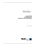
4. Polarization - Do not defeat the safety
purpose of the polarized or
grounding-type plug.
A polarized plug has two blades with
one wider than the other.
A grounding type plug has two blades
and a third grounding prong.
The wide blade or the third prong are
provided for your safety.
If the provided plug does not fit into your outlet, consult
an electrician for replacement of the obsolete outlet.
5. Power Sources - This product should be operated only
from the type of power source indicated on the marking
label. If you are not sure of the type of power supplied
to your location, consult your video dealer or local power
company. For products intended to operate from battery
power, or other sources, refer to the operating
instructions.
6. Overloading - Do not overload wall outlets or
extension cords as this can result in the risk of fire or
electric shock. Overloaded AC outlets, extension
cords, frayed power cords, damaged or cracked wire
insulation, and broken plugs are dangerous. They may
result in a shock or fire hazard. Periodically examine
the cord, and if its appearance indicates damage or
deteriorated insulation, have it replaced by your
service technician.
7. Power-Cord Protection - Power supply cords should
be routed so that they are not likely to be walked on or
pinched by items placed upon or against them. Pay
particular attention to cords at plugs, convenience
receptacles, and the point where they exit from the
product.
8. Surge Protectors - It is highly recommended that the
product be connected to a surge protector. Doing so
will protect the product from damage caused by power
surges. Surge protectors should bear the UL listing
mark or CSA certification mark.
9. Uninterruptible Power Supplies (UPS) - Because
this product is designed for continuous,
24/7 operation, it is recommended that you connect
the product to an uninterruptible power supply. An
uninterruptible power supply has an internal battery
that will keep the product running in the event of a
power outage. Uninterruptible power supplies should
bear the UL listing mark or CSA certification mark.
Caution: Maintain electrical safety. Power line
operated equipment or accessories connected to this
product should bear the UL listing mark or CSA
certification mark on the accessory itself and should
not be modified so as to defeat the safety features. This
will help avoid any potential hazard from electrical
shock or fire. If in doubt, contact qualified service
personnel.
v
Installation (Continued)
Service
10. Ventilation - Slots and openings in the case are
provided for ventilation to ensure reliable operation of
the product and to protect it from overheating. These
openings must not be blocked or covered. The
openings should never be blocked by placing the
product on a bed, sofa, rug, or other similar surface.
This product should never be placed near or over a
radiator or heat register. This product should not be
placed in a built-in installation such as a bookcase or
rack unless proper ventilation is provided and the
product manufacturer’s instructions have been
followed.
1. Servicing - Do not attempt to service this product
yourself, as opening or removing covers may expose
you to dangerous voltage or other hazards. Refer all
servicing to qualified service personnel.
11. Attachments - Do not use attachments unless
recommended by the product manufacturer as they
may cause a hazard.
12. Water and Moisture - Do not use this product near
water — for example, near a bath tub, wash bowl,
kitchen sink or laundry tub, in a wet basement, near a
swimming pool and the like.
13. Heat - The product should be situated away from heat
sources such as radiators, heat registers, stoves, or
other products (including amplifiers) that produce
heat.
14. Accessories - Do not place this
product on an unstable cart,
stand, tripod, or table. The product
may fall, causing serious damage
to the product. Use this product
only with a cart, stand, tripod,
bracket, or table recommended by
the manufacturer or sold with the
product. Any mounting of the
product should follow the manufacturer’s instructions
and use a mounting accessory recommended by the
manufacturer.
15. Camera Extension Cables – Check the rating of
your extension cable(s) to verify compliance with your
local authority regulations prior to installation.
16. Mounting - The cameras provided with this system
should be mounted only as instructed in this guide or
the instructions that came with your cameras, using
the provided mounting brackets.
17. Camera Installation- Cameras are not intended for
submersion in water. Not all cameras can be installed
outdoors. Check your camera environmental rating to
confirm if they can be installed outdoors. When
installing cameras outdoors, installation in a sheltered
area is required.
2. Conditions Requiring Service - Unplug this product
from the wall outlet and refer servicing to qualified
service personnel under the following conditions:
A. When the power supply cord or plug is damaged.
B. If liquid has been spilled or objects have fallen into
the product.
C. If the product has been exposed to rain or water.
D. If the product has been dropped or the cabinet has
been damaged.
E. If the product does not operate normally by
following the operating instructions. Adjust only those
controls that are covered by the operating
instructions. Improper adjustment of other controls
may result in damage and will often require extensive
work by a qualified technician to restore the product
to its normal operation.
F. When the product exhibits a distinct change in
performance. This indicates a need for service.
7. Replacement Parts - When replacement parts are
required, have the service technician verify that the
replacements used have the same safety
characteristics as the original parts. Use of
replacements specified by the product manufacturer
can prevent fire, electric shock, or other hazards.
8. Safety Check - Upon completion of any service or
repairs to this product, ask the service technician to
perform safety checks recommended by the
manufacturer to determine that the product is in safe
operating condition.
Use
1. Cleaning - Unplug the product from the wall outlet
before cleaning. Do not use liquid cleaners or aerosol
cleaners. Use a damp cloth for cleaning.
2. Product and Cart Combination - When product is
installed on a cart, product and cart combination
should be moved with care. Quick stops, excessive
force, and uneven surfaces may cause the product and
cart combination to overturn.
3. Object and Liquid Entry - Never push objects of any
kind into this product through openings as they may
touch dangerous voltage points or “short-out” parts
that could result in a fire or electric shock. Never spill
liquid of any kind on the product.
4. Lightning - For added protection of this product
during a lightning storm, or when it is left unattended
and unused for long periods of time, unplug it from
the wall outlet and disconnect the antenna or cable
system. This will prevent damage to the product due
to lightning and power line surges.
WARNING: This product contains a button battery. If swallowed, it could cause
severe injury or death in just two hours. Seek medical attention immediately.
vi
NOTICES
FCC/IC Notice:
This equipment has been tested and found to comply with the limits for a Class B digital device, pursuant
to Part 15 of the FCC Rules. These limits are designed to provide reasonable protection against harmful
interference in a residential installation. This equipment generates, uses, and can radiate radio frequency
energy and, if not installed and used in accordance with the instruction, may cause harmful interference
to radio communications.
However, there is no guarantee that interference will not occur in a particular installation. If this
equipment does cause harmful interference to radio or television reception (which can be determined by
turning the equipment on and off), the user is encouraged to try to correct the interference by one or more
of the following measures:
• Reorient or relocate the receiving antenna
• Increase the separation between the equipment and receiver
• Connect the equipment into an outlet on a circuit different from that to which the receiver is connected
• Consult the dealer or an experienced radio or television technician for assistance
Modification:
Any changes or modifications not expressly approved by the grantee of this device could void the user's
authority to operate the device.
Toute modification non approuvée explicitement par le fournisseur de licence de l'appareil peut entraîner
l'annulation du droit de l'utilsateur à utiliser l'appareil.
RoHS:
This product is fully compliant with the European Union Restriction of the Use of Certain Hazardous
Substances in Electrical and Electronic Equipment ("RoHS") Directive (2002/95/EC). The RoHS directive
prohibits the sale of electronic equipment containing certain hazardous substances such as lead,
cadmium, mercury, and hexavalent chromium, PBB, and PBDE in the European Union.
This product has been certified and found to comply with the limits regulated by FCC, EMC, and
LVD. Therefore, it is designated to provide reasonable protection against interference and will not
cause interference with other appliance usage.
However, it is imperative that the user follows the guidelines in this manual to avoid improper
usage, which may result in damage to the product, electrical shock and fire hazard injury.
In order to improve the features, functions, and quality of this product, the specifications are
subject to change without notice from time to time.
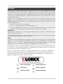
www.lorextechnology.com
Product Information
Specification Sheets
User Manuals
Software Upgrades
Quick Start Guides
Firmware Upgrades
vii
EDGE2 Series Features
Digital Video Recorder Features
• HDMI output in full 1080p – simple connection to HDTVs1
• Touch Screen navigation compatible2
• 24x7 100% duty cycle HDD
• Pentaplex operation - View, Record, Playback, Backup & Remotely control the system
simultaneously
• Recording options: Motion, schedule, or continuous
• Small form factor (11.6 x 6.5 x 1.3”)
• 3 x USB 2.0 ports (mouse, touch screen monitor, backup, firmware upgrade)
• VESA Mount (easily mounts to the back of an LCD monitor)3
• “Flex” IR extender for remote control (line-of-sight not required)
• Swipe-to-Switch dynamic allocation of camera location in live viewing
• Scroll-to-Search through recorded event list with image preview
• PTZ cameras supported (RS-485)
Connectivity Features4
• Instant Mobile Viewing on compatible Smartphones5
• Exclusive LOREX Easy Connect Internet Set-up Wizard
• Lorex Edge Client Software:
• PC (Microsoft Windows™ 8 / 7 / Vista / XP compatible) using client software (included)
and web browser
• Mac remote client software (included)
• Free LOREX DDNS (Dynamic Domain Name Service) for advanced remote connectivity at all
times
• Instant email alerts with snap shot attachments and web link
1. HDMI output 1080p (1920x1080) for high definition multi-channel live viewing only. High definition recording not
supported. Recording resolution is limited to a maximum of 704x480 per channel. Image quality and resolution
is dependent on the type of camera connected to the DVR.
2. Touch operation with Windows™ 7 Touch compatible touch screen monitor via USB connection.
3. Easily mounts to the back of an LCD monitor with VESA standard mounting holes and an independent stand.
Requires clear access to the 100 x100 mm VESA mounting holes.
4. Requires a high speed internet connection and a router (not included).
5. Instant Mobile Viewing on iPad™, iPhone™, and BlackBerry (supported model numbers: 9000, 9700, 9800),
Android (v. 2.1). Selectable one channel live viewing. Mobile phone data plan is required (not included). Router
port forwarding required. For the latest smart phone compatibility list check www.lorextechnology.com as new
smart phone models become available in the market.
viii
EDGE3 Series Features
Digital Video Recorder Features
• 960H (960x480) recording resolution1
• HDMI output in full 1080p – simple connection to HDTVs2
• Touch Screen navigation compatible3
• 24x7 100% duty cycle HDD
• Pentaplex operation - View, Record, Playback, Backup & Remotely control the system
simultaneously
• Recording options: Motion, schedule, or continuous
• Small form factor (11.6 x 6.5 x 1.3”)
• 3 x USB 2.0 (mouse, touch monitor, backup, firmware upgrade)
• VESA Mount (easily mounts to the back of an LCD monitor)
• “Flex” IR controller (line-of-sight not required)
• Mirror Hard Drive Recording4
• Expandable Hard Drive Storage
• PTZ cameras supported (RS485)
Connectivity Features5
• Advanced Management Software
• Instant Mobile Viewing on compatible Smartphones6
• Exclusive LOREX Easy Connect Internet Set-up Wizard
• PC (Microsoft Windows™ 8 / 7 / Vista / XP compatible) using Internet Explorer®
• Mac full function remote software
• Free LOREX DDNS (Dynamic Domain Name Service) for advanced remote connectivity at all
times
• Instant e-mail alerts with snap shot attachments and web link
1. When used with 960H compatible cameras. DVR is backwards compatible and supports different camera inputs:
standard resolution and 960H.
2. HDMI output 1080p (1920x1080) for high definition multi-channel live viewing only. High definition recording not
supported. Recording resolution is limited to a maximum of 960x480 per channel. Image quality and resolution
is dependent on the type of camera connected to the DVR.
3. Touch operation with Windows™ 7 compatible touch screen monitor via USB connection.
4. Hard drive mirroring and External storage expansion are selectable options. You select one or the other, but not
both at the same time. The DVR supports a single external USB hard drive up to a maximum size of 2TB. The
external hard drive must be self-powered to work with the system; it cannot receive power from the DVR’s USB
port. Footage on the external hard drive can only be accessed using the DVR or a Windows PC. The footage cannot be accessed on a Mac.
5. Requires a high speed internet connection and a router (not included).
6. Instant Mobile Viewing on iPad®, iPhone®, BlackBerry (supported model numbers: 8900, 9000, 9700, 9800),
Android (version 1.5 & above). Mobile phone data plan is required (not included). Router port forwarding
required. For the latest smart phone compatibility list check www.lorextechnology.com as new smart phone
models become available in the market.
ix
x
TABLE OF CONTENTS
Getting Started . . . . . . . . . . . . . . . . . . . . . . . . . . . . . . . . . . . . . . . . . . . . . . . . . 1
Front Panel . . . . . . . . . . . . . . . . . . . . . . . . . . . . . . . . . . . . . . . . . . . . . . . . . . . . . . . . . . . . . 2
Rear Panel (8-Channel) . . . . . . . . . . . . . . . . . . . . . . . . . . . . . . . . . . . . . . . . . . . . . . . . . . . 3
Rear Panel (16-Channel) . . . . . . . . . . . . . . . . . . . . . . . . . . . . . . . . . . . . . . . . . . . . . . . . . 4
Basic Setup . . . . . . . . . . . . . . . . . . . . . . . . . . . . . . . . . . . . . . . . . . . . . . . . . . . . . . . . . . . . . 5
Step 1: Connect the BNC Cameras . . . . . . . . . . . . . . . . . . . . . . . . . . . . . . . . . . . . . . . . . . . . . . . . . . . . . . . 5
Step 2: Connect the Monitor . . . . . . . . . . . . . . . . . . . . . . . . . . . . . . . . . . . . . . . . . . . . . . . . . . . . . . . . . . . . . 6
Step 3: Connect the Mouse . . . . . . . . . . . . . . . . . . . . . . . . . . . . . . . . . . . . . . . . . . . . . . . . . . . . . . . . . . . . . 6
Step 4: Connect the Ethernet Cable . . . . . . . . . . . . . . . . . . . . . . . . . . . . . . . . . . . . . . . . . . . . . . . . . . . . . . 7
Step 5: Connect the Flex IR Extender (Optional) . . . . . . . . . . . . . . . . . . . . . . . . . . . . . . . . . . . . . . . . . . . . 7
Step 6: Connect the Power Adapter . . . . . . . . . . . . . . . . . . . . . . . . . . . . . . . . . . . . . . . . . . . . . . . . . . . . . . 7
Step 7: Verify Camera Image . . . . . . . . . . . . . . . . . . . . . . . . . . . . . . . . . . . . . . . . . . . . . . . . . . . . . . . . . . . . 8
Step 8: Set the Time . . . . . . . . . . . . . . . . . . . . . . . . . . . . . . . . . . . . . . . . . . . . . . . . . . . . . . . . . . . . . . . . . . . 8
Accessing System Information . . . . . . . . . . . . . . . . . . . . . . . . . . . . . . . . . . . . . . . . . . . . . 8
Default System Passwords . . . . . . . . . . . . . . . . . . . . . . . . . . . . . . . . . . . . . . . . . . . . . . . . 8
Connecting Cameras . . . . . . . . . . . . . . . . . . . . . . . . . . . . . . . . . . . . . . . . . . . . . . . . . . . . . 9
Installation Tips . . . . . . . . . . . . . . . . . . . . . . . . . . . . . . . . . . . . . . . . . . . . . . . . . . . . . . . . . . . . . . . . . . . . . . . 9
Installing Cameras . . . . . . . . . . . . . . . . . . . . . . . . . . . . . . . . . . . . . . . . . . . . . . . . . . . . . . . . . . . . . . . . . . . . 9
Connecting BNC Cameras to your DVR . . . . . . . . . . . . . . . . . . . . . . . . . . . . . . . . . . . . . . . . . . . . . . . . . . . 10
Connecting and Removing BNC Cables . . . . . . . . . . . . . . . . . . . . . . . . . . . . . . . . . . . . . . . . . . . . . . . . . . 10
Touch Screen Control . . . . . . . . . . . . . . . . . . . . . . . . . . . . . . . . . . . . . . . . . . . . . . . . . . . 11
Mouse Control . . . . . . . . . . . . . . . . . . . . . . . . . . . . . . . . . . . . . . . . . . . . . . . . . . . . . . . . . 11
Remote Control . . . . . . . . . . . . . . . . . . . . . . . . . . . . . . . . . . . . . . . . . . . . . . . . . . . . . . . . 12
Controls Quick Reference . . . . . . . . . . . . . . . . . . . . . . . . . . . . . . . . . . . . . . . . . . . . . . . . 13
On-screen Display . . . . . . . . . . . . . . . . . . . . . . . . . . . . . . . . . . . . . . . . . . . . . 14
Using the On-Screen Keyboard . . . . . . . . . . . . . . . . . . . . . . . . . . . . . . . . . . . . . . . . . . . 16
Using the Split-Screen Selector . . . . . . . . . . . . . . . . . . . . . . . . . . . . . . . . . . . . . . . . . . 16
Flexible Camera Assignment (Swipe-to-Switch) . . . . . . . . . . . . . . . . . . . . . . . . . . . . 17
Using Sequence View . . . . . . . . . . . . . . . . . . . . . . . . . . . . . . . . . . . . . . . . . . . . . . . . . . . . 18
Setting the Date and Time . . . . . . . . . . . . . . . . . . . . . . . . . . . . . . . . . . . . . . . 19
Recording. . . . . . . . . . . . . . . . . . . . . . . . . . . . . . . . . . . . . . . . . . . . . . . . . . . . . 20
Event Recording . . . . . . . . . . . . . . . . . . . . . . . . . . . . . . . . . . . . . . . . . . . . . . . . . . . . . . . . 20
Recording Audio . . . . . . . . . . . . . . . . . . . . . . . . . . . . . . . . . . . . . . . . . . . . . . . . . . . . . . . . 20
Event List . . . . . . . . . . . . . . . . . . . . . . . . . . . . . . . . . . . . . . . . . . . . . . . . . . . . . 21
Channel Filter . . . . . . . . . . . . . . . . . . . . . . . . . . . . . . . . . . . . . . . . . . . . . . . . . . . . . . . . . . . . . . . . . . . . . . . 22
Event Details . . . . . . . . . . . . . . . . . . . . . . . . . . . . . . . . . . . . . . . . . . . . . . . . . . . . . . . . . . . . . . . . . . . . . . . . 22
Searching for Recorded Data (Scroll-to-Search) . . . . . . . . . . . . . . . . . . . . . . . . . . . . . . . . . . . . . . . . . . . 22
Playback. . . . . . . . . . . . . . . . . . . . . . . . . . . . . . . . . . . . . . . . . . . . . . . . . . . . . . 24
xi
The Playback Bar, Playback Markers, and Smart Search Markers . . . . . . . . . . . . . 25
Playback and Smart Search Markers . . . . . . . . . . . . . . . . . . . . . . . . . . . . . . . . . . . . . . . . . . . . . . . . . . . . 25
Taking Screenshots . . . . . . . . . . . . . . . . . . . . . . . . . . . . . . . . . . . . . . . . . . . . 26
Using Screenshots . . . . . . . . . . . . . . . . . . . . . . . . . . . . . . . . . . . . . . . . . . . . . . . . . . . . . . 27
Managing Passwords . . . . . . . . . . . . . . . . . . . . . . . . . . . . . . . . . . . . . . . . . . . 28
User Accounts . . . . . . . . . . . . . . . . . . . . . . . . . . . . . . . . . . . . . . . . . . . . . . . . . . . . . . . . . 28
Using the Password Wheel . . . . . . . . . . . . . . . . . . . . . . . . . . . . . . . . . . . . . . . . . . . . . . . 28
Enabling and Disabling Passwords . . . . . . . . . . . . . . . . . . . . . . . . . . . . . . . . . . . . . . . . 29
Changing Passwords . . . . . . . . . . . . . . . . . . . . . . . . . . . . . . . . . . . . . . . . . . . . . . . . . . . . 29
Using the Main Menu . . . . . . . . . . . . . . . . . . . . . . . . . . . . . . . . . . . . . . . . . . . 30
Camera . . . . . . . . . . . . . . . . . . . . . . . . . . . . . . . . . . . . . . . . . . . . . . . . . . . . . . . . . . . . . . . 31
Configuring Camera Color Settings . . . . . . . . . . . . . . . . . . . . . . . . . . . . . . . . . . . . . . . . . . . . . . . . . . . . . 31
Configuring the Covert Setting (Hidden Cameras) . . . . . . . . . . . . . . . . . . . . . . . . . . . . . . . . . . . . . . . . . . 31
Changing the Camera Title Display . . . . . . . . . . . . . . . . . . . . . . . . . . . . . . . . . . . . . . . . . . . . . . . . . . . . . . 32
Changing the Sequence Dwell Time . . . . . . . . . . . . . . . . . . . . . . . . . . . . . . . . . . . . . . . . . . . . . . . . . . . . . 32
Changing the Camera Input Mode (EDGE3 Only) . . . . . . . . . . . . . . . . . . . . . . . . . . . . . . . . . . . . . . . . . . . 32
Setup . . . . . . . . . . . . . . . . . . . . . . . . . . . . . . . . . . . . . . . . . . . . . . . . . . . . . . . . . . . . . . . . . 33
Changing the Resolution and Video Output Mode . . . . . . . . . . . . . . . . . . . . . . . . . . . . . . . . . . . . . . . . . . 33
Accessing System Information . . . . . . . . . . . . . . . . . . . . . . . . . . . . . . . . . . . . . . . . . . . . . . . . . . . . . . . . . 33
Changing the Fan Speed . . . . . . . . . . . . . . . . . . . . . . . . . . . . . . . . . . . . . . . . . . . . . . . . . . . . . . . . . . . . . . . 33
Selecting PAL or NTSC . . . . . . . . . . . . . . . . . . . . . . . . . . . . . . . . . . . . . . . . . . . . . . . . . . . . . . . . . . . . . . . . 33
Changing the System Language . . . . . . . . . . . . . . . . . . . . . . . . . . . . . . . . . . . . . . . . . . . . . . . . . . . . . . . . 33
Adjusting HDMI Screen Size . . . . . . . . . . . . . . . . . . . . . . . . . . . . . . . . . . . . . . . . . . . . . . . . . . . . . . . . . . . . 33
Resetting the DVR to Factory Default Settings . . . . . . . . . . . . . . . . . . . . . . . . . . . . . . . . . . . . . . . . . . . . . 34
Saving your System Configuration to a USB Flash Drive . . . . . . . . . . . . . . . . . . . . . . . . . . . . . . . . . . . . 34
Loading a System Configuration from a USB Drive . . . . . . . . . . . . . . . . . . . . . . . . . . . . . . . . . . . . . . . . . 34
Record . . . . . . . . . . . . . . . . . . . . . . . . . . . . . . . . . . . . . . . . . . . . . . . . . . . . . . . . . . . . . . . . 35
Configuring Camera Frame Rate and Video Quality . . . . . . . . . . . . . . . . . . . . . . . . . . . . . . . . . . . . . . . . 35
Reading the Storage Calculator . . . . . . . . . . . . . . . . . . . . . . . . . . . . . . . . . . . . . . . . . . . . . . . . . . . . . . . . . 36
Configuring the Recording Schedule . . . . . . . . . . . . . . . . . . . . . . . . . . . . . . . . . . . . . . . . . . . . . . . . . . . . 36
Viewing Hard Drive Information . . . . . . . . . . . . . . . . . . . . . . . . . . . . . . . . . . . . . . . . . . . . . . . . . . . . . . . . . 36
Changing the Record Mode . . . . . . . . . . . . . . . . . . . . . . . . . . . . . . . . . . . . . . . . . . . . . . . . . . . . . . . . . . . . 37
Formatting Hard Drives . . . . . . . . . . . . . . . . . . . . . . . . . . . . . . . . . . . . . . . . . . . . . . . . . . . . . . . . . . . . . . . 37
External Hard Drive Mirroring or Extension . . . . . . . . . . . . . . . . . . . . . . . . . . . . . . . . . . . . . . . . . . . . . . . 37
Configuring your External Hard Drive for HDD Mirroring or Extension . . . . . . . . . . . . . . . . . . . . . . . . . 39
Playing Back Video from the External Hard Drive . . . . . . . . . . . . . . . . . . . . . . . . . . . . . . . . . . . . . . . . . . 39
Alarm . . . . . . . . . . . . . . . . . . . . . . . . . . . . . . . . . . . . . . . . . . . . . . . . . . . . . . . . . . . . . . . . . 40
Enabling / Disabling System Buzzers . . . . . . . . . . . . . . . . . . . . . . . . . . . . . . . . . . . . . . . . . . . . . . . . . . . . 40
Enabling / Disabling Motion Detection . . . . . . . . . . . . . . . . . . . . . . . . . . . . . . . . . . . . . . . . . . . . . . . . . . . 40
Enabling / Disabling Video Loss Alarms . . . . . . . . . . . . . . . . . . . . . . . . . . . . . . . . . . . . . . . . . . . . . . . . . . 40
Configuring Alarm Settings . . . . . . . . . . . . . . . . . . . . . . . . . . . . . . . . . . . . . . . . . . . . . . . . . . . . . . . . . . . . 40
Configuring the Motion Alarm Schedule . . . . . . . . . . . . . . . . . . . . . . . . . . . . . . . . . . . . . . . . . . . . . . . . . . 41
Configuring the DVR for Motion Recording Only . . . . . . . . . . . . . . . . . . . . . . . . . . . . . . . . . . . . . . . . . . . 41
Configuring Motion Detection Areas and Sensitivity . . . . . . . . . . . . . . . . . . . . . . . . . . . . . . . . . . . . . . . . 42
Backup . . . . . . . . . . . . . . . . . . . . . . . . . . . . . . . . . . . . . . . . . . . . . . . . . . . . . . . . . . . . . . . . 43
Formatting the USB Drive . . . . . . . . . . . . . . . . . . . . . . . . . . . . . . . . . . . . . . . . . . . . . . . . . . . . . . . . . . . . . 43
xii
Backing up Video to a USB Flash Drive . . . . . . . . . . . . . . . . . . . . . . . . . . . . . . . . . . . . . . . . . . . . . . . . . . . 44
Confirming Backup . . . . . . . . . . . . . . . . . . . . . . . . . . . . . . . . . . . . . . . . . . . . . . . . . . . . . . . . . . . . . . . . . . . 44
Backup File Information . . . . . . . . . . . . . . . . . . . . . . . . . . . . . . . . . . . . . . . . . . . . . . . . . . . . . . . . . . . . . . . 44
Playing Backed-up Video on your Computer . . . . . . . . . . . . . . . . . . . . . . . . . . . . . . . . . . . . . . . . . . . . . . 44
Setting QuickTime Player as a Default Media Player (PC) . . . . . . . . . . . . . . . . . . . . . . . . . . . . . . . . . . . 45
LAN . . . . . . . . . . . . . . . . . . . . . . . . . . . . . . . . . . . . . . . . . . . . . . . . . . . . . . . . . . . . . . . . . . 46
Changing the HTTP Port . . . . . . . . . . . . . . . . . . . . . . . . . . . . . . . . . . . . . . . . . . . . . . . . . . . . . . . . . . . . . . . 46
Configuring Network Settings . . . . . . . . . . . . . . . . . . . . . . . . . . . . . . . . . . . . . . . . . . . . . . . . . . . . . . . . . . 47
Configuring Remote Access Passwords . . . . . . . . . . . . . . . . . . . . . . . . . . . . . . . . . . . . . . . . . . . . . . . . . . 47
Configuring Dual Streaming Settings . . . . . . . . . . . . . . . . . . . . . . . . . . . . . . . . . . . . . . . . . . . . . . . . . . . . 48
Configuring DDNS Settings . . . . . . . . . . . . . . . . . . . . . . . . . . . . . . . . . . . . . . . . . . . . . . . . . . . . . . . . . . . . 48
Configuring Email Alerts . . . . . . . . . . . . . . . . . . . . . . . . . . . . . . . . . . . . . . . . . . . . . . . . . . . . . . . . . . . . . . 49
Enabling/Disabling UPnP . . . . . . . . . . . . . . . . . . . . . . . . . . . . . . . . . . . . . . . . . . . . . . . . . . . . . . . . . . . . . . 50
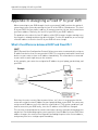
Setting up your DVR for Remote Connectivity. . . . . . . . . . . . . . . . . . . . . . . 51
System Requirements . . . . . . . . . . . . . . . . . . . . . . . . . . . . . . . . . . . . . . . . . . . . . . . . . . . 51
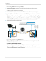
Accessing your DVR Within a Local Network (LAN) . . . . . . . . . . . . . . . . . . . . . . . . . . 51
Step 1 of 4: Connect your DVR to the Local Area Network (LAN) . . . . . . . . . . . . . . . . . . . . . . . . . . . . . . 51
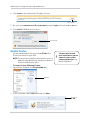
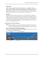
Step 2 of 4: Obtain the DVR’s Local IP Address and HTTP Port . . . . . . . . . . . . . . . . . . . . . . . . . . . . . . . 52
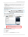
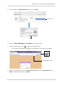
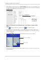
Step 3 of 4: Install the Client Software on your PC or Mac . . . . . . . . . . . . . . . . . . . . . . . . . . . . . . . . . . . 53
Step 4 of 4: Configure the Client Software and Confirm Local Connection . . . . . . . . . . . . . . . . . . . . . . 53
Accessing your DVR Remotely Over the Internet . . . . . . . . . . . . . . . . . . . . . . . . . . . . 55
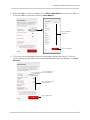
Step 1 of 4: Port Forwarding . . . . . . . . . . . . . . . . . . . . . . . . . . . . . . . . . . . . . . . . . . . . . . . . . . . . . . . . . . . 55
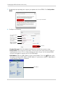
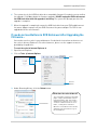
Step 2 of 4: Create a DDNS Account . . . . . . . . . . . . . . . . . . . . . . . . . . . . . . . . . . . . . . . . . . . . . . . . . . . . . 55
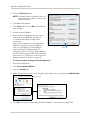
Step 3 of 4: Enable DDNS on the DVR . . . . . . . . . . . . . . . . . . . . . . . . . . . . . . . . . . . . . . . . . . . . . . . . . . . . 59
Step 4 of 4: Update the Client Software with your DDNS Information . . . . . . . . . . . . . . . . . . . . . . . . . . 60
Advanced Networking Configuration (Optional) . . . . . . . . . . . . . . . . . . . . . . . . . . . . . 61
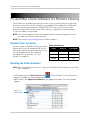
PC and Mac Client Software for Remote Viewing . . . . . . . . . . . . . . . . . . . . 62
Network User Accounts . . . . . . . . . . . . . . . . . . . . . . . . . . . . . . . . . . . . . . . . . . . . . . . . . 62
Running the Client Software . . . . . . . . . . . . . . . . . . . . . . . . . . . . . . . . . . . . . . . . . . . . . 62
Client Window . . . . . . . . . . . . . . . . . . . . . . . . . . . . . . . . . . . . . . . . . . . . . . . . . . . . . . . . . . 63
DVR List: Managing DVRs . . . . . . . . . . . . . . . . . . . . . . . . . . . . . . . . . . . . . . . . . . . . . . . . 64
Adding a DVR . . . . . . . . . . . . . . . . . . . . . . . . . . . . . . . . . . . . . . . . . . . . . . . . . . . . . . . . . . . . . . . . . . . . . . . . 64
Changing DVR Settings . . . . . . . . . . . . . . . . . . . . . . . . . . . . . . . . . . . . . . . . . . . . . . . . . . . . . . . . . . . . . . . . 65
Deleting a DVR . . . . . . . . . . . . . . . . . . . . . . . . . . . . . . . . . . . . . . . . . . . . . . . . . . . . . . . . . . . . . . . . . . . . . . 65
Live Viewing Mode . . . . . . . . . . . . . . . . . . . . . . . . . . . . . . . . . . . . . . . . . . . . . . . . . . . . . . 66
Playback Mode . . . . . . . . . . . . . . . . . . . . . . . . . . . . . . . . . . . . . . . . . . . . . . . . . . . . . . . . . 66
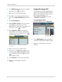
Using the Pop-Up Calendar . . . . . . . . . . . . . . . . . . . . . . . . . . . . . . . . . . . . . . . . . . . . . . . . . . . . . . . . . . . . 67
Backup Mode . . . . . . . . . . . . . . . . . . . . . . . . . . . . . . . . . . . . . . . . . . . . . . . . . . . . . . . . . . 67
Setup Mode . . . . . . . . . . . . . . . . . . . . . . . . . . . . . . . . . . . . . . . . . . . . . . . . . . . . . . . . . . . . 68
Changing Bitrate Speed . . . . . . . . . . . . . . . . . . . . . . . . . . . . . . . . . . . . . . . . . . . . . . . . . . . . . . . . . . . . . . . 69
Enabling PPPoE . . . . . . . . . . . . . . . . . . . . . . . . . . . . . . . . . . . . . . . . . . . . . . . . . . . . . . . . . . . . . . . . . . . . . 69
Enabling DDNS . . . . . . . . . . . . . . . . . . . . . . . . . . . . . . . . . . . . . . . . . . . . . . . . . . . . . . . . . . . . . . . . . . . . . . 69
Viewing System Status . . . . . . . . . . . . . . . . . . . . . . . . . . . . . . . . . . . . . . . . . . . . . . . . . . . . . . . . . . . . . . . . 70
Configuring Email Alerts . . . . . . . . . . . . . . . . . . . . . . . . . . . . . . . . . . . . . . . . . . . . . . . . . . . . . . . . . . . . . . 70
Creating Custom Camera Titles . . . . . . . . . . . . . . . . . . . . . . . . . . . . . . . . . . . . . . . . . . . . . . . . . . . . . . . . 71
Taking Screenshots (PC Only) . . . . . . . . . . . . . . . . . . . . . . . . . . . . . . . . . . . . . . . . . . . . 72
xiii
Manual Recording (PC Only) . . . . . . . . . . . . . . . . . . . . . . . . . . . . . . . . . . . . . . . . . . . . . . 73
Accessing Remote Speed Dome Settings (PTZ Controls) (PC Only) . . . . . . . . . . . . . 73
Using the HDD Reader (PC Only) . . . . . . . . . . . . . . . . . . . . . . . . . . . . . . . . . . . . . . . . . . 74
DVR Netviewer: Viewing Your DVR Using a Web Browser . . . . . . . . . . . . 76
Connecting to your DVR Using a DDNS or IP Address . . . . . . . . . . . . . . . . . . . . . . . . . 76
Connecting to the DVR over a LAN Using UPnP . . . . . . . . . . . . . . . . . . . . . . . . . . . . . . 77
Internet Explorer . . . . . . . . . . . . . . . . . . . . . . . . . . . . . . . . . . . . . . . . . . . . . . . . . . . . . . . . . . . . . . . . . . . . . . . . . . 78
Internet Explorer 9 / 10 . . . . . . . . . . . . . . . . . . . . . . . . . . . . . . . . . . . . . . . . . . . . . . . . . . . . . . . . . . . . . . . 79
Mozilla Firefox . . . . . . . . . . . . . . . . . . . . . . . . . . . . . . . . . . . . . . . . . . . . . . . . . . . . . . . . . . . . . . . . . . . . . . . . . . . . . 80
Google Chrome . . . . . . . . . . . . . . . . . . . . . . . . . . . . . . . . . . . . . . . . . . . . . . . . . . . . . . . . . . . . . . . . . . . . . . . . . . . . 82
Mobile Apps: Accessing your DVR Using a Mobile Device . . . . . . . . . . . . . 85
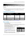
Compatible Devices and Platforms . . . . . . . . . . . . . . . . . . . . . . . . . . . . . . . . . . . . . . . . 85
Before You Begin . . . . . . . . . . . . . . . . . . . . . . . . . . . . . . . . . . . . . . . . . . . . . . . . . . . . . . . 85
iPhone / iPad App . . . . . . . . . . . . . . . . . . . . . . . . . . . . . . . . . . . . . . . . . . . . . . . . . . . . . . . . . . . . . . . . . . . . . . . . . . 86
Downloading the Lorex Live Application on iPhone / iPad . . . . . . . . . . . . . . . . . . . . . . . . . . . . . . . . . . . 86
Connecting To Your DVR on the iPhone . . . . . . . . . . . . . . . . . . . . . . . . . . . . . . . . . . . . . . . . . . . . . . . . . . 86
The Lorex Live Interface . . . . . . . . . . . . . . . . . . . . . . . . . . . . . . . . . . . . . . . . . . . . . . . . . . . . . . . . . . . . . . . 87
Connecting To Your DVR on the iPad . . . . . . . . . . . . . . . . . . . . . . . . . . . . . . . . . . . . . . . . . . . . . . . . . . . . . 88
Using the Address Book on the iPhone / iPad . . . . . . . . . . . . . . . . . . . . . . . . . . . . . . . . . . . . . . . . . . . . . 90
Accessing Backed up Video on the iPad . . . . . . . . . . . . . . . . . . . . . . . . . . . . . . . . . . . . . . . . . . . . . . . . . . 91
Android App . . . . . . . . . . . . . . . . . . . . . . . . . . . . . . . . . . . . . . . . . . . . . . . . . . . . . . . . . . . 92
Connecting to your DVR on Android . . . . . . . . . . . . . . . . . . . . . . . . . . . . . . . . . . . . . . . . . . . . . . . . . . . . . 92
Lorex Mobile Edge Viewing Interface . . . . . . . . . . . . . . . . . . . . . . . . . . . . . . . . . . . . . . . . . . . . . . . . . . . . 93
Setup Menu . . . . . . . . . . . . . . . . . . . . . . . . . . . . . . . . . . . . . . . . . . . . . . . . . . . . . . . . . . . . . . . . . . . . . . . . . 93
Playback Mode . . . . . . . . . . . . . . . . . . . . . . . . . . . . . . . . . . . . . . . . . . . . . . . . . . . . . . . . . . . . . . . . . . . . . . 94
PTZ Controls . . . . . . . . . . . . . . . . . . . . . . . . . . . . . . . . . . . . . . . . . . . . . . . . . . . . . . . . . . . . . . . . . . . . . . . . 95
Address Book . . . . . . . . . . . . . . . . . . . . . . . . . . . . . . . . . . . . . . . . . . . . . . . . . . . . . . . . . . . . . . . . . . . . . . . 96
Blackberry App . . . . . . . . . . . . . . . . . . . . . . . . . . . . . . . . . . . . . . . . . . . . . . . . . . . . . . . . 97
Installing Mobile View on the Blackberry: . . . . . . . . . . . . . . . . . . . . . . . . . . . . . . . . . . . . . . . . . . . . . . . . 97
Connecting to your DVR on your Blackberry . . . . . . . . . . . . . . . . . . . . . . . . . . . . . . . . . . . . . . . . . . . . . . 98
Viewing Your DVR on your Blackberry . . . . . . . . . . . . . . . . . . . . . . . . . . . . . . . . . . . . . . . . . . . . . . . . . . . 99
Enabling APN (Access Point Name) on Your Blackberry . . . . . . . . . . . . . . . . . . . . . . . . . . . . . . . . . . . 100
Appendix A: System Specifications . . . . . . . . . . . . . . . . . . . . . . . . . . . . . . 102
EDGE2 Series . . . . . . . . . . . . . . . . . . . . . . . . . . . . . . . . . . . . . . . . . . . . . . . . . . . . . . . . . 102
EDGE3 Series . . . . . . . . . . . . . . . . . . . . . . . . . . . . . . . . . . . . . . . . . . . . . . . . . . . . . . . . . 103
Appendix B: Assigning a Fixed IP to your DVR . . . . . . . . . . . . . . . . . . . . . 104
What’s the difference between DHCP and Fixed IPs? . . . . . . . . . . . . . . . . . . . . . . . . 104
Setting up a Fixed IP Address . . . . . . . . . . . . . . . . . . . . . . . . . . . . . . . . . . . . . . . . . . . 105
Appendix C: Connecting PTZ Cameras. . . . . . . . . . . . . . . . . . . . . . . . . . . . 108
Controlling PTZ Cameras . . . . . . . . . . . . . . . . . . . . . . . . . . . . . . . . . . . . . . . . . . . . . . . 109
Using PTZ Presets . . . . . . . . . . . . . . . . . . . . . . . . . . . . . . . . . . . . . . . . . . . . . . . . . . . . . . . . . . . . . . . . . . 109
Appendix D: Recording and Playing Audio . . . . . . . . . . . . . . . . . . . . . . . . 111
xiv
Connecting an Audio-Capable Camera or Self-Powered Microphone . . . . . . . . . . 111
Playing Audio from your DVR . . . . . . . . . . . . . . . . . . . . . . . . . . . . . . . . . . . . . . . . . . . . 112
Appendix E: Mounting the DVR to a VESA Mount . . . . . . . . . . . . . . . . . . . 113
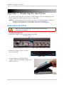
Appendix F: Replacing the Hard Drive . . . . . . . . . . . . . . . . . . . . . . . . . . . . 114
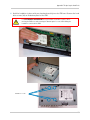
Removing the Hard Drive . . . . . . . . . . . . . . . . . . . . . . . . . . . . . . . . . . . . . . . . . . . . . . . 114
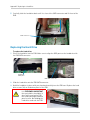
Replacing the Hard Drive . . . . . . . . . . . . . . . . . . . . . . . . . . . . . . . . . . . . . . . . . . . . . . . 116
Formatting the Hard Drive . . . . . . . . . . . . . . . . . . . . . . . . . . . . . . . . . . . . . . . . . . . . . . 117
Appendix G: Upgrading Firmware . . . . . . . . . . . . . . . . . . . . . . . . . . . . . . . 118
If you do not see Buttons in DVR Netviewer After Upgrading the Firmware... . . . 119
Troubleshooting . . . . . . . . . . . . . . . . . . . . . . . . . . . . . . . . . . . . . . . . . . . . . . 121
Troubleshooting Remote Connections . . . . . . . . . . . . . . . . . . . . . . . . . . . . . . . . . . . . 124
xv
xvi
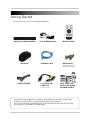
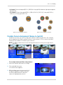
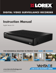
Getting Started
The system comes with the following components:
DVR (DIGITAL VIDEO RECORDER)*
12V DC POWER ADAPTER
USB MOUSE
ETHERNET CABLE
REMOTE CONTROL
MOUNTING KIT
(Mounting Kit contents
may differ from image)
FLEX IR EXTENDER
2 X OCTOPUS BNC
CONNECTOR
(16-channel only)
QUICK START GUIDE
INSTRUCTION MANUAL
DOCUMENTATION CD
*HARD DRIVE SIZE, NUMBER OF CHANNELS, AND CAMERA CONFIGURATION MAY VARY
BY MODEL. PLEASE REFER TO YOUR PACKAGE FOR SPECIFIC DETAILS.
CHECK YOUR PACKAGE TO CONFIRM THAT YOU HAVE RECEIVED THE COMPLETE SYSTEM,
INCLUDING ALL COMPONENTS SHOWN ABOVE.
1
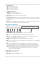
Front Panel
1
1
2
3
4
5
6
7
8
9
Playback Controls:
• : In Playback mode, press to rewind video. Press repeatedly to increase rewind speed.
• While playback is paused, press to move back playback time or date.
• In menus, press to change settings.
: In Viewing mode, press to enter Playback mode.
•
• In Playback mode, press to play video. Press again to pause video playback.
• : In Playback mode, press to fast forward video. Press repeatedly to increase fast forward
speed.
• While playback is paused, press to advance playback time or date.
• In menus, press to change settings.
2
Quad/Split-screen View:
•
3
: Press to open the Split-Screen Selector. From Full Screen / Single-Channel view, press
to switch to Split-Screen view.
Channel Selection:
• CH-: Press to select previous channel.
• While in Split-Screen view, press to open previously selected channel in full-screen view.
• CH+: Press to select next channel.
• While in Split-Screen view, press to open previously selected channel in full-screen view.
4
Menu Controls:
•
: Press to go back / exit menus.
• In Playback mode, press to return to Viewing mode.
• In Full Screen / Single-Channel mode, press to return to Split-screen view.
•
•
: Press to enter Main Menu.
: Press to confirm menu selections.
• In Viewing mode, press to access System Information.
• In Playback mode, press to create a Playback Marker.
2
5
Navigation Buttons:
• : Press to move cursor up.
• : Press to move cursor down.
• : Press to move cursor left.
• : Press to move cursor right.
6
Hard Drive / Power LED:
• Solid: Device is on / powering up.
• Flashing: Device is recording to hard drive.
7
IR Receiver: Internal IR receiver for the remote control.
8
Flex IR Extender Port: Connect the Flex IR Extender to increase the remote control range or
use the remote control without needing line of sight to the DVR (must have line of sight to Flex
IR Extender).
9
USB Ports: Connect a USB mouse (included), touch screen monitor (not included), or a USB
flash drive (not included) for data backup and firmware updates.
Rear Panel (8-Channel)
1
2
3
4
5
6
7
8
9
1
DC 12V: Connect the included DC power adapter to power on the DVR.
2
LAN: Connect a CAT 5 RJ45 Ethernet cable for local and remote connectivity.
3
HDMI: Connect to an HDMI-compatible TV or monitor (not included). Note that the DVR
cannot use a VGA and HDMI monitor at the same time.
4
RS485: Connect RS485 cables for compatible PTZ cameras (not included).
5
VGA: Connect to a VGA monitor (not included). Note that the DVR cannot use a VGA and HDMI
monitor at the same time.
6
USB: Connect to a Windows 7® Touch compatible touch screen monitor (not included),
mouse (included), USB flash drive (not included) for data backup and firmware updates), or
self-powered external hard drive (not included) for disk mirroring (PC required) or expansion.
NOTE: The DVR supports a single external hard drive up to a maximum size of 2TB. The
external hard drive must be self-powered to work with the system; it cannot receive
power from the DVR’s USB port.
7
Audio Out: Output for audio channel.
8
Audio In: Input for audio channel.
9
BNC Video In: Connect up to 8 BNC cameras.
3
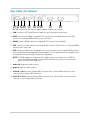
Rear Panel (16-Channel)
1
2
3
4
5
6
7
8
9
10
1
DC 12V: Connect the included DC power adapter to power on the DVR.
2
LAN: Connect a CAT 5 RJ45 Ethernet cable for local and remote connectivity.
3
HDMI: Connect to an HDMI-compatible TV or monitor (not included). Note that the DVR
cannot use a VGA and HDMI monitor at the same time.
4
RS485: Connect RS485 cables for compatible PTZ cameras (not included).
5
VGA: Connect to a VGA monitor (not included). Note that the DVR cannot use a VGA and HDMI
monitor at the same time.
6
USB: Connect a USB mouse (included), touch screen monitor (not included), USB flash drive
(not included) for data backup and firmware updates, or self-powered external hard drive (not
included) for disk mirroring (PC required) or expansion.
NOTE: The DVR supports a single external hard drive up to a maximum size of 2TB. The
external hard drive must be self-powered to work with the system; it cannot receive
power from the DVR’s USB port.
7
Audio Out: Output for audio channel.
8
Audio In: Input for audio channel.
9
Video IN 1~8CH: Connect Octopus BNC connector here. Connect BNC connectors from
cameras 1-8 to Octopus BNC connector.
10 Video IN 9~16CH: Connect Octopus BNC connector here. Connect BNC connectors from
cameras 9-16 to Octopus BNC connector.
4
Basic Setup
NOTE: This DVR features unique mounting options and can be mounted to back of LCD
monitors with a VESA mount. For mounting instructions, see “Appendix E: Mounting
the DVR to a VESA Mount” on page 113. If you intend to mount the DVR, it is
recommended to do so before completing setup.
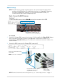
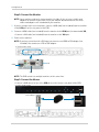
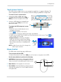
Step 1: Connect the BNC Cameras
8-channel
• Connect the BNC cameras to the Video IN ports on the rear panel of the DVR.
Push and twist the BNC connector
clockwise to secure it to the BNC port.
16-channel
1
Connect the Octopus BNC connector for channels 1-8 (included) to the Video IN CH 1~8 port
on the rear panel of the DVR. Connect the Octopus BNC connector for channels 9-16
(included) to the Video IN CH9~16 port. The label at the end of each connector indicates the
channel number.
2
Connect the BNC cameras to the Octopus BNC connector(s).
Connect this end to Video In port
on your DVR
NOTE: Do not connect to VGA port
Push and twist the BNC connector
clockwise to secure it to the
Octopus BNC connector
Labels indicate
channel number
NOTE: For more information on installing cameras, see “Connecting Cameras” on page 9.
5
Getting Started
Step 2: Connect the Monitor
NOTE: Lorex monitors and touch screen monitors include all the necessary cables and
adapters to connect to your DVR. Check your monitor documentation to see which
cables and adapters are included with your monitor.
1
If you are using a touch screen monitor, connect a USB cable (not included) from the monitor
to the USB port on the rear panel of the DVR.
2
Connect a HDMI cable (not included) from the monitor to the HDMI port (recommended) OR;
• Connect a VGA cable (not included) from the monitor to the VGA port.
3
Power on the monitor.
NOTE: If you have a monitor with a DVI input, you must use an HDMI to DVI adapter (not
included). You cannot use a DVI to VGA adapter.
8-channel model shown
USB
HDMI
VGA
NOTE: The DVR cannot use multiple monitors at the same time.
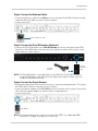
Step 3: Connect the Mouse
• Connect a USB mouse to one of the USB ports on the front or rear panel of the DVR.
8-channel model shown
Rear USB port
Front USB ports
6
Getting Started
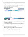
Step 4: Connect the Ethernet Cable
• Connect the Ethernet cable to the LAN port on the rear panel of the DVR. Connect the other
end of the Ethernet cable to a router on your network.
8-channel model shown
Connect Ethernet cable
Step 5: Connect the Flex IR Extender (Optional)
• Connect the Flex IR Extender to the Flex IR Extender port on the front panel of the DVR.
Position the Flex IR Extender near the front of the monitor or where it will receive a clear
signal from the remote control.
Flex IR
Extender
Flex IR
Extender
port
NOTE: The Flex IR Extender is not required to use the DVR. Use the Flex IR Extender to
install the DVR where it will not have line of sight to the remote control, such as in
a cabinet or behind the monitor.
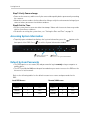
Step 6: Connect the Power Adapter
• Before powering up the DVR, ensure the monitor is connected and powered on. This allows
the DVR to detect the best resolution for your monitor.
• Connect the power adapter to the DC 12V port on the rear panel of the system. Connect the
other end of the power adapter to a power outlet or surge protector.
8-channel model shown
DC 12V port
NOTE: If the top or bottom of the screen is cut off on your HDTV, see “Adjusting HDMI
Screen Size” on page 33 to adjust the screen size.
7
Getting Started
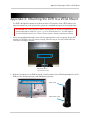
Step 7: Verify Camera Image
• Power on the cameras, and then verify the camera video quality before permanently mounting
the cameras.
• Mount the cameras under a sheltered location. Always verify the environmental rating of your
cameras before permanent installation outdoors.
Step 8: Set the Time
• Set the system time for accurate video timestamps. Videos with inaccurate times may not be
valid as surveillance evidence.
• For details on setting the system time, see “Setting the Date and Time” on page 19.
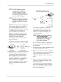
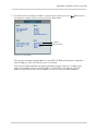
Accessing System Information
• To quickly open a window that displays vital system information, press the
front panel of the DVR. Press
button on the
to exit the System Information window.
button - Press to exit
system information
button -
Press to access system information
Default System Passwords
• The DVR requires a user name (ID) and password to log in remotely using a computer or
mobile device.
• The HTTP port (default 80) must be port forwarded on your router to access the DVR over the
Internet or a local network.
Refer to the following tables for the default account user names and passwords for the
DVR.
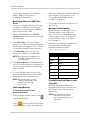
Local DVR Access:
8
Remote/LAN Access:
Level
User ID
Password
Level
User ID
Password
USER1
1
1111
USER1
7
1111
USER2
2
2222
USER2
8
2222
ADMIN
3
3333
ADMIN
9
3333
Getting Started
Connecting Cameras
ATTENTION: Cameras differ in terms of installation or mounting instructions. Please see
the documentation that came with your camera(s) for specific installation instructions.
Test the cameras before permanent installation. Plan where you will route the wiring for
the camera and where you will aim the camera.
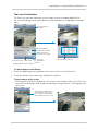
Installation Tips
• Mount the camera where the lens is away from direct and intense sunlight.
• Plan your cable wiring so that it does not interfere with power lines or telephone lines.
• Ensure that the camera wiring is not exposed or easily cut.
• Mount the camera in an area that is visible, but out of reach.
• Avoid pointing the camera at a glass window to see outside, as this may result in a poor image
caused by glare from indoor / outdoor lighting conditions.
• Adjust the camera angle so that it covers an area with high traffic.
• In "high-risk" locations, have multiple cameras point in the same area. This provides camera
redundancy if a vandal attempts to damage the camera.
Installing Cameras
1
Mount the camera(s) to the desired mounting surface according to the instructions that came
with the camera(s). Choose a firm mounting surface.
NOTE: If you wish to mount cameras to drywall, it is recommended to use drywall plugs
(not included).
2
Adjust the camera stand to ensure that the camera has a satisfactory view of the area you
would like to monitor. Stand configuration depends on the mounting surface you have chosen
(see below for suggested stand configurations).
Wall Mount
Table Mount
Ceiling Mount
Camera model not be exactly as shown.
NOTE: There are two connection points for certain cameras. Secure the stand to the top
thread for wall mounts or ceiling mounts. Secure the stand to the bottom thread
for table mounts or wall mounts.
Secure to camera
thread
Top thread
(Ceiling mount, Wall mount)
Bottom thread
(Table mount)
Camera model may not be exactly as shown.
9
Getting Started
Connecting BNC Cameras to your DVR
1
Connect the male power connector on the BNC extension cable to the female power
connector on the camera.
• Connect the BNC connector to the camera.
2
Connect the female power connector on the BNC extension cable to the power adapter.
3
(8-channel) Connect the BNC connector to one of the Video In ports on the rear panel of the
DVR.
• (16-channel) Connect the Octopus BNC connector for channels 1-8 (included) to the Video
IN CH 1~8 port and the Octopus BNC connector for channels 9-16 (included) to the Video IN
CH9~16 port on the rear panel of the DVR. Connect the BNC cameras to the Octopus BNC
connector(s). The label at the end of each connector indicates the channel number.
4
Plug the power adapter to a power outlet.
Digital Video Recorder
(8-channel model shown)
BNC Extension cable
Male power connector
Female power connector
Connecting and Removing BNC Cables
BNC (Bayonet Nut Connector) is a special connector that locks on to the system port and
cannot be accidently removed.
To connect or remove a BNC connector:
• Push the BNC connector firmly into the BNC port and simultaneously twist the connector
clockwise to tighten.
• To remove a BNC connector from a BNC port, push and simultaneously twist the connector
counter-clockwise to loosen the BNC connector.
10
Getting Started
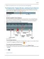
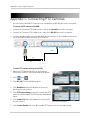
Touch Screen Control
This DVR features unique touch screen navigation capabilities. It supports Windows 7®
Touch compatible touch screen monitors without needing any additional configuration.
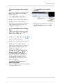
To connect a touch screen monitor:
1 Connect the VGA or HDMI cable (not
included) from the monitor to the VGA or
HDMI port on the rear panel of the DVR.
2
Connect a USB cable (not included) from
the monitor to the USB port on the rear
panel of the DVR.
USB
HDMI
To navigate the DVR using touch screen
controls:
• Touch the icons on the display to access
/ navigate the menus.
to go back / exit menus.
• Touch
• Change menu settings by swiping your finger up and down.
VGA
• In Split-Screen mode, Touch a camera to view that camera in full-screen. Touch
return to Split-Screen mode.
• Swipe-to-Switch: In Viewing or Playback
mode, you can switch cameras by swiping
your finger left or right. Release your finger
when the desired camera is highlighted to
select it.
to
NOTE: In Split-Screen view, this changes the
order of your cameras.
Mouse Control
The DVR can be controlled using a USB mouse.
To use a mouse with the DVR:
• Connect the mouse to one of the USB ports on the front or rear panels of the DVR.
Use the mouse buttons to perform the following:
1 Left-Button: Click to select a menu option. While in
Split-Screen mode (Viewing or Playback), click on a
camera to view the selected channel in full-screen.
2
Right-Button: Click to go back / exit menus.
3
Scroll-Wheel: Scroll up / down to change values in
selected menu options or select Playback Markers
in Playback Bar.
1
2
3
11
Getting Started
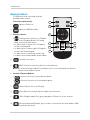
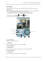
Remote Control
The DVR can also be controlled using the
included remote control.
To use the remote control:
1
: Open the Event List.
2
: Opens the DVR Main Menu.
3
Primary Controls:
•
1
7
2
8
3
: Confirm menu selections; in Playback
mode, create Playback Marker; in Viewing
mode, view system information.
• : Move cursor in menus left; in Playback,
increase rewind speed.
• : Move cursor in menus right; in Playback,
increase fast-forward speed.
• : Move cursor in menus up; channel up.
• : Move cursor in menus down; channel down.
4
9
5
10
6
4
: Go back / exit menus.
5
: While in Event List, press to delete the selected event.
NOTE: Be careful when pressing the Trash button—there is no confirmation for deletion
and you cannot undo the action.
6
Increase / Decrease Buttons:
•
: Increase the value of selected menu option.
•
: Decrease the value of selected menu option.
7
: Show / hide the On-screen Display.
8
: Enter Split-Screen mode; Open the Split-Screen Selector.
9
: Enter Playback mode; Play / pause playback; In Event List, select event for
playback.
10
: During Viewing and Playback, press to take a screenshot of the main display—USB
flash drive must be connected.
12
Getting Started
Controls Quick Reference
The following chart shows how to navigate the menus using the various control options
available on the DVR.
Using:
Select
Option:
Change Setting:
Go Back /
Exit Menu:
Right-click
Mouse
Left-click
Scroll wheel up /
down
Touch Screen
Tap
Swipe up / down or
left / right
Remote
Control
DVR Front
Panel
Move
Cursor
N/A
N/A
/
/
13
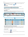
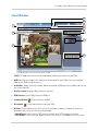
On-screen Display
On-screen Display
ATTENTION: The instructions in this manual describe how to operate the DVR
using a mouse (included). When using a touch screen monitor (not included),
simply touch the on-screen buttons when told to click, swipe your finger
horizontally or vertically to scroll up / down, and touch
to right-click and exit
menus. All the features of this DVR can be accessed using a touch screen monitor.
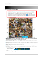
16-channel model shown
1
Display Screen: Shows live and recorded video in Full-screen / Single-Channel mode and
Split-Screen (16-way split on 16-channel model only) view.
2
Camera Number / Title: You can set the DVR to show the camera number, title, or no title.
3
Channels: Displays channels on the DVR. Icons flash red to indicate recording is in progress.
4
Date / Time: Displays the date and time on the DVR.
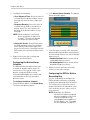
5
HDD Status: Displays the size of the pre-installed hard drive (for example, 1000GB) and the
recording space consumed on the hard disk (%).
Total size of hard drive
NOTE: This reading is an approximation.
14
Percent full
On-screen Display
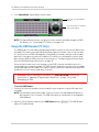
6
Toolbar: Move the mouse to the bottom of the screen to view the toolbar. Click these buttons
to access the menus and control the DVR.
NOTE: Additional buttons are shown in some screens.
•
: Click to open the Split-Screen Selector; In Full Screen / Single Channel mode, click to
open Split-screen view.
•
: Click to open the Main Menu. See “Using the Main Menu” on page 30.
•
: Click to move cursor left in menus.
•
: Click to move cursor right in menus.
•
: From Viewing mode, click to open Playback mode. Click to play / pause video.
•
: Click to rewind / increase rewind speed (only available during playback).
•
: Click to fast forward / increase fast forward speed (only available during playback).
•
: Click to open the Event List. See “Event List” on page 21.
•
: Click to begin Sequence view. In Sequence view, the DVR automatically switches
between connected cameras in Full Screen / Single Channel view. Click
view.
to exit Sequence
•
: Click to turn the On-Screen Display on / off.
•
: Click to go back / exit menus.
•
: Click to take a screenshot of the active display (live viewing or playback).
NOTE: USB flash drive (not included) must be connected. For more details, see “Taking Screenshots”
on page 26.
•
: From the Event List, click to delete a selected video file.
NOTE: Be careful when clicking the Trash icon—there is no confirmation for deletion and you cannot
undo the action.
•
: Click to access PTZ controls.
NOTE: PTZ camera(s) must be connected. For instructions, see “Appendix C: Connecting PTZ
Cameras” on page 108.
•
: Click to close the on-screen keyboard and cancel current entry.
15
On-screen Display
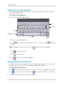
Using the On-Screen Keyboard
An on-screen keyboard appears when entering certain menu options that require text input
(for example, Email setup).
To use the on-screen keyboard:
1 Click on a menu field that requires text.
Delete
Confirm
entry
Shift
Numbers & Special
Characters
Space
Cancel
Entry
• The on-screen keyboard appears.
• Click
to letters.
for numbers or special characters (e.g. ".", "@", etc.). Click
NOTE: For additional special characters, click
• Click
to delete characters.
• Click
to confirm entry.
• Click
to cancel entry and exit keyboard.
to go back
from the numerical keyboard.
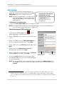
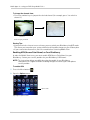
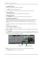
Using the Split-Screen Selector
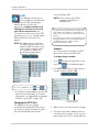
The Split-Screen Selector allows you to choose the grid layout for Split-Screen view. Quad
(4-way), 9-way, and 16-way (16-channel only) split options are available.
To use the Split-screen Selector:
1
2
16
Click
to open the Split-Screen Selector. If you are in Full Screen / Single Channel view,
click
to go to Split-Screen view, and click
again to open the Split-Screen Selector.
Click a grid configuration for live viewing or playback:
On-screen Display
• 8-channel: Choose from quad (CH1~4, CH5~8) or 9-way split (the bottom-right square appears
blacked out).
• 16-channel: Choose from quad (CH1~4, CH5~8, CH9-12, CH13~16), 9-way split (CH1~9,
CH10~2), or 16-way split (CH1~16).
Split-screen Selector (8-channel)
Split-screen Selector (16-channel)
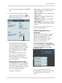
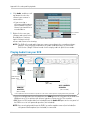
Flexible Camera Assignment (Swipe-to-Switch)
In Split-Screen view, you can re-assign your cameras to different positions. For example,
you can duplicate the video feed from channel 1 onto channel 2. This is useful if you wish
to obscure the number or location of your cameras.
NOTE: The DVR records cameras to their designated channels even if you reassign camera
positions.
Example: Channel 3 is reassigned to channel 5.
1
To re-assign camera positions using a mouse:
Select the channel you want to re-assign.
2
Click and hold the mouse.
• A camera menu appears.
3
While holding, move the mouse to the left
or right to change the camera. Release
the mouse button when the desired
camera is highlighted to select it.
17
On-screen Display
To re-assign camera positions using
a touch screen monitor:
1 Press and hold your finger on the
channel you want to re-assign.
• A camera menu appears.
NOTE: Tapping on the screen may
cause the DVR to switch to
Single-Channel / Full-Screen
mode. If it does this, press the
button to return to
Split-Screen view.
2
Move your finger from left to right to change the channel. Release your finger when the
desired camera is highlighted to select it.
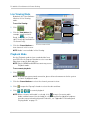
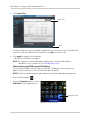
Using Sequence View
In Sequence view, the DVR automatically switches between camera channels every few
seconds (for instructions on changing the amount of time channels are shown before
switching, see “Changing the Sequence Dwell Time” on page 32). The following modes are
available for Sequence view:
• Single-channel Sequence: The DVR
automatically switches between connected
cameras in full-screen.
• 4-way Sequence: The DVR switches between
every channel, showing 4 channels at a time.
4-way Sequence
Single-channel Sequence
To enter / exit Sequence view:
to enter Sequence view. Sequence
• Click
view uses the last mode selected.
to exit Sequence view and return
• Click
to Split-Screen mode.
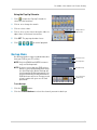
Sequence Mode Selector
To change the Sequence mode:
1
Click
2
Click
18
while viewing in Sequence view. The Sequence Mode Selector appears.
to select 4-way Sequence or
for Single-channel Sequence.
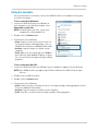
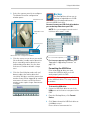
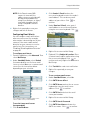
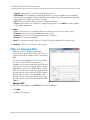
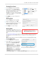
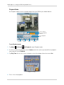
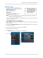
Setting the Date and Time
It is highly recommended to immediately set the date and time
when first setting up your DVR.
Inaccurate time stamps may render your footage unusable as
court evidence.
To set the date and time:
to open the Main Menu.
1
Click
2
Click
3
Click Date/Time Setup. The Date/Time
Setup Menu appears.
4
Configure the following:
• Date Mode: Scroll up / down to select the
date format you would like to use (Y/M/D,
D/M/Y, or M/Y/D). The Date field
automatically changes to the chosen
format when selected.
Date/Time Setup Menu
• Date Setup: Scroll up / down to manually
select the date.
• Time Setup: Scroll up / down to manually select the time.
to open the Setup Menu.
NOTE: The DVR displays time in 24-hour format.
5
Click Exit/Update to save your settings. The system returns to the Setup Menu.
6
Right-click until all menus are closed. The date and time are displayed on the bottom-left
corner of the screen.
NOTE: The system does not automatically adjust the time for Daylight Savings Time.
Remember to change the time one hour ahead, or one hour backward, according
to Daylight Savings Time. When the time is set backwards, the system will retain
recorded data with overlapping time stamps.
19
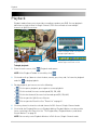
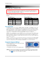
Recording
By default, the system is set to immediately record video from all connected cameras in
Continuous Record Mode.
You can set the system to stop recording once the hard drive is full, or to continually record
by overwriting previously recorded data. For more details, see “Record” on page 35.
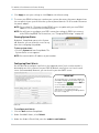
Event Recording
The DVR includes the following modes of event recording:
•
Motion: The DVR records when motion is detected by the affected camera.
•
Video Loss: The DVR records when a camera is disconnected or suffers video loss.
The system employs a pre-record function to capture video seconds before events occur.
Recording Audio
The system can record one audio channel. You must have an audio-enabled camera or
self-powered microphone connected to the system in order to use this function.
For details, see “Appendix D: Recording and Playing Audio” on page 111.
20
Event List
Event List
The system features an Event List to organize and search for recorded video on the system.
Events in the Event List are marked with Smart Search icons, which allows you to search
for recorded data on your system quickly and easily.
NOTE: The system can save a maximum of 8196 events.
To access the Event List:
• Click LIST or press the LIST button on the remote control.
NOTE: You cannot access the Event List using the buttons on the front panel of the DVR.
1
2
3
4
5
1
Channel Filter: View data from all cameras or from individual cameras.
2
Smart Search: Filter events through Smart Search icons, which indicate the type of event.
3
Event Details: View details for the event, including date & time and event source.
4
Events: List of recorded events on the system.
21
Event List
5
Active Toolbar Buttons: While in Event List, click
(
) to delete events (cannot undo), and
to select events for playback, Trash
to exit.
Channel Filter
Use the Channel Filter to sort the data from individual channels or all channels.
NOTE: Filters for channels 9~16 are shown in the Event List for the 8-channel model but
are not click-able.
Event Details
An event number, camera number, filter type, date & time, and event source are shown for
each event in the Event List. When you use the Channel Filter and Event Filter, the Event
Details Bar Helps you view event details at a glance.
Event Number
Camera Number
OR Type of System
Event
Filter Type
Date & Time
Event Source
Event Details Bar
Searching for Recorded Data (Scroll-to-Search)
Scroll-to-Search allows you to easily search through saved events and see a preview of the
recorded video. You can access the Event List from Viewing mode and Playback mode to
search for recorded data on your system.
To search for data:
1
From the main screen, click
. The Event List opens.
2
Under Channel Filter, click
to view events for ALL channels, or click the Channel icons
to view events from individual channels.
22
Event List
3
Click the Smart Search icons to sort the data according to the following:
•
ALL: View all events chronologically.
NOTE: USB backups appear at the top of the list if a USB flash drive with saved
backup data is connected.
•
•
•
Motion: Motion events from the selected camera(s).
Video Loss: Camera(s) are disconnected or suffer video loss. The system employs
a pre-record function to capture video seconds before the loss of video occurred.
HDD/System: Hard drive connection / disconnection, power loss, or disk failure.
Shows D/T when the system date and time has been changed.
•
•
Power ON/OFF: System ON/OFF.
Playback Mark: A personal marker set by the user during Playback Mode. For details,
see “The Playback Bar, Playback Markers, and Smart Search Markers” on page 25.
•
USB: USB backup performed by the user.
4
Scroll up / down to view the events on the list.
• With a touch screen monitor, touch
inside the list of events and move your
finger up / down to scroll.
5
Click an event. A preview of the
recorded video appears behind the
Event List window.
6
Selected
event
. System switches to
Click
Playback Mode.
Preview of
recorded
video
NOTE: If the Playback toolbar does not
appear, click
.
NOTE: You cannot begin playback after
clicking
7
Scroll-to-Search shows you a preview of your
recorded video when you select an event
or
To exit, right-click until you return to the main screen.
23
Playback
Playback
Playback mode allows you to view video recordings saved on your DVR. You can playback
video from a single channel in Single-Channel / Full-Screen mode or from multiple
channels in Split-Screen view.
Use the Playback Toolbar to select the time
and date for playback and create and search
through Playback Markers
The playback time appears in the
bottom-right corner of the screen
Playback display view
To begin playback:
1
From the main screen, click
. Playback mode opens.
NOTE: If the Playback Toolbar is not visible, click
2
Click and scroll up / down to select the date, month, year, time, and / or frame for playback
and click
3
.
to begin playback.
During playback, you have access to the following:
•
: Click to pause playback; press again to resume playback.
•
: Click to rewind / increase rewind speed (5X, 15X, 60X).
•
: Click to fast forward / increase fast forward speed (5X, 15X, 60X).
•
: Click to open the Split-Screen Selector.
•
: Click to open the Event List. See “Event List” on page 21.
4
Click any channel to view the selected channel in Full-Screen / Single-Channel mode.
5
Click inside the Playback Bar to set a Playback Marker. Playback Markers can be used for
faster searching in the Event List. See “The Playback Bar, Playback Markers, and Smart
Search Markers” on page 25.
NOTE: You can only create Playback Markers in Full-Screen / Single-Channel mode.
24
Playback
6
Right-click anywhere on the screen to exit and return to Viewing mode.
The Playback Bar, Playback Markers, and Smart Search Markers
The Playback Bar shows recorded video data and events on the DVR based on the time they
were recorded. The Playback Bar is black when there is no video available for a given time,
and it is colored when video is available for a given time.
Video not available
Video available
Playback Bar
Playback and Smart Search Markers
Events on the DVR are represented by different colored markers (see the diagram below).
These markers are part of the Smart Search functionality of the system. For more details
on Smart Search, see “Event List” on page 21. You can also create your own Playback
Markers at any point during Playback mode.
Search markers1
To create Playback Markers:
• Click anywhere inside the Playback Bar. A Playback Marker appears at the Playback Target.
An event is also added to the Event List with a
icon.
To use Smart Search and Playback Markers:
1 Scroll up / down to position one of the colored markers in the Playback Target.
• Using a touch screen monitor, touch any of the Time and Date Selectors and move your finger
up / down.
2
Click
.
1. Graphics simulated.
25
Taking Screenshots
Taking Screenshots
ATTENTION: Video footage is preferable to screenshots when submitting surveillance
evidence in court. For instructions on how to backup or extract video footage from your DVR,
see “Backup” on page 43.
You can take screenshots (screen captures) of the main display of your system at any time:
during live viewing, search, and playback, or in any system menu. Screenshots are useful
if you need to provide a still image of your security footage to the authorities.
NOTE: A USB flash drive (not included) must be connected to the system and formatted
in order to take screenshots. For instructions on how to format USB flash drives,
see “Formatting the USB Drive” on page 43.
1
2
3
To take a screenshot:
Connect a USB flash drive (not
included) to one of the USB ports on
the DVR. Format the USB flash drive
if you have not already done so.
If you want to capture a moment in
Viewing or Playback mode, select the
display view for the screenshot:
full-screen or split-screen.
. The screenshot appears
Click
in the center of the main display,
followed by the file name.
Screenshots are saved to the Picture
folder on the USB flash drive.
Screenshot
Filename
Screenshot being taken on the system
NOTE: Screenshots are saved as
JPEG files with the following
naming convention:
NmmDD00x.jpg
Filename
26
Definition
N
System file marker
mm
Month
DD
Day
x
Numeral (e.g. 001, 002, 003, etc.)
Taking Screenshots
Using Screenshots
Once you have taken screenshots, connect the USB flash drive to a computer to view, print,
or archive the images.
To use screenshots (Windows):
1 Connect the USB flash drive to a USB port on
your computer. In the AutoPlay window, select
Open folder to view files.
NOTE: If AutoPlay does not start, search your
computer for a Removable Disk.
2
Double-click the Picture folder.
3
Perform one of the following:
• View: Double-click the screenshot to view it in
an image viewing or editing program, such as
Windows Picture Viewer or Adobe® Photoshop™
• Archive: Copy the images to a folder on your
computer
• Print: Right-click the image and select Print to
print it directly from Windows Explorer, or print
the screenshot from an image viewing or editing
program.
AutoPlay window
To use screenshots (Mac OS):
1 Connect the USB flash drive to a USB port on your computer. It appears on your desktop.
NOTE: If the USB drive does not appear, open Finder and locate the USB flash drive under
Devices.
2
Double-click the USB flash drive.
3
Double-click the Picture folder.
4
Perform one of the following:
• View: Double-click the screenshot to view it in an image viewing or editing program, such as
Preview or Adobe® Photoshop™
• Archive: Copy the images to a folder on your computer.
• Print: Print the screenshot from an image viewing or editing program.
27
Managing Passwords
Managing Passwords
ATTENTION: By default, passwords are disabled on the system, which allows anyone to
access the menus and change DVR settings. It is recommended to enable passwords. See
“Enabling and Disabling Passwords” on page 29.
Refer to the tables below for the user name (ID) and password required to log in to your
system:
Local DVR Access:
Remote/LAN Access:
LEVEL
ID
PASSWORD
LEVEL
ID
PASSWORD
USER1
1
1111
USER1
7
1111
USER2
2
2222
USER2
8
2222
ADMIN
3
3333
ADMIN
9
3333
User Accounts
The DVR has three user accounts: ADMIN, USER2, and USER1. The ADMIN account is the
system administrator. The ADMIN can access all the menus and can configure the DVR
both locally and from a remote computer. The ADMIN can also see covert cameras when
he is logged in from a remote computer or mobile device. For information on covert
cameras, see “Configuring the Covert Setting (Hidden Cameras)” on page 31.
USER2 is the standard user account. USER2 can access all the menus on the DVR except
for the Setup Menu. USER2 can view and backup recorded footage when logged into the
DVR from a remote computer or mobile device but cannot access the remote setup menu
or see covert cameras.
USER1 is a limited access user account that cannot access any menus on the DVR. USER1
can view cameras when logged in from a remote computer or mobile device but cannot
access the setup menus, view or backup recorded video, or see covert cameras.
Using the Password Wheel
The Password Wheel is used to input and change
user IDs and passwords.
To use the Password Wheel:
• Click 0~9 to enter your user ID and password.
Login with your user ID and password using the
Password Wheel
NOTE: You cannot select the options to the left of the Password Wheel (user ID, password)—
you can only select the digits. If you make a mistake, simply right-click to exit or
and re-select the option to try again.
click
28
Managing Passwords
Enabling and Disabling Passwords
By default, passwords are disabled. With passwords enabled, you need to enter your user
ID and password to access the system Main Menu, Event List, or Playback mode.
To enable/disable passwords:
1
to open the Main Menu. Enter your
Click
user ID and password if needed.
2
Click
3
Click DVR Password. The DVR Password menu
opens.
4
Click Password Enable and scroll up / down to
select O to enable passwords or X to disable.
5
Right-click until you have exited all menus to save your changes.
. The Setup menu opens.
DVR Password Menu
NOTE: When you are logged in, this icon is shown at the top-left corner of the screen:
from
The number represents your user ID. To log out, right-click or click
Viewing mode.
.
Changing Passwords
If passwords are enabled, you must be
logged in as ADMIN in order to change
passwords.
To change passwords:
1
Click
to open the Main Menu.
2
Click
. The Setup menu opens.
3
Click DVR Password. The Password Wheel
opens. Enter the ADMIN user ID and
password if needed.
4
Click the account you would like to change.
5
Use the Password Wheel to enter a 4-digit
password. Enter it again to confirm.
6
Right-click until you have exited all menus
to save your changes.
Enter the new password twice to change passwords
Password change confirmation
NOTE: To change the Remote Access
passwords see “Configuring Remote
Access Passwords” on page 47.
29
Using the Main Menu
Using the Main Menu
To open the Main Menu:
, OR press the
• Click
to open sub-menus.
1
4
button on the front panel of the DVR. Click on the icons below
2
3
5
6
1
Camera: Adjust brightness, contrast, hue, and saturation for each camera. Configure camera
title display, sequence time, and Covert (hidden camera) settings.
2
Setup: Configure date / time, language, video settings, passwords, and fan speed. View
system information.
3
Record: Configure video parameters for recording.
Configure recording mode and schedule. Configure
camera frame rate, video quality, resolution, and audio
settings. Format hard drive. View video information.
4
Alarm: Configure alarm, motion, and video loss settings.
Enable / disable system buzzers.
5
Backup: Backup recorded video to a USB flash drive.
Select start time, stop time, and video channel for
backup. Format connected USB flash drive.
6
LAN: View / configure networking settings.
30
Tip!
See the “Controls Quick Reference”
on page 13 for instructions on
navigating the menus with the
various control options available.
Using the Main Menu
Camera
The Camera Menu allows you to
adjust the picture settings for
your cameras and configure camera
title display, sequence time, and Covert
(hidden camera) settings. Configure PTZ
cameras (RS-485 settings).
Camera color adjust settings
4
Scroll up / down to increase / decrease the
value for the selected option.
5
Right-click to save your settings and
return to the Camera menu.
Configuring the Covert Setting
(Hidden Cameras)
Camera Menu
To access the Camera Menu, click
then
The Covert setting allows you to hide
cameras on the DVR, so users cannot
see them. Cameras that are hidden
using the Covert setting can only be
viewed remotely (i.e. through a local
network or the Internet) by the ADMIN
account.
.
• For instructions on configuring PTZ
cameras, see “Appendix C: Connecting
PTZ Cameras” on page 108.
Configuring Camera Color Settings
1
From the Camera menu, select Adjust.
2
Select the camera you would like to
configure. The Camera Color Settings
Menu opens.
3
Configure the following:
• Brightness
• Contrast
• Hue
• Saturation
NOTE: It is highly recommended to
enable passwords when using
the Covert settings. If
passwords are not enabled, then
anyone can change Covert
settings and un-hide the
cameras. If passwords are
enabled, only the ADMIN and
USER2 accounts can change
Covert settings.
1
2
31
To configure Covert settings:
From the Camera Menu, click Covert
under the camera you would like to hide /
un-hide.
Move the cursor to the camera you would
like to hide / un-hide and scroll up / down
to change the Covert settings.
• X - Visible (Covert OFF).
• O - Hidden (Covert ON).
Using the Main Menu
3
Right-click until you have exited all menus
to save your settings.
Changing the Camera Input Mode
(EDGE3 Only)
Changing the Camera Title Display
The Video-In Mode is used to select if
your DVR inputs video from cameras in
wide-screen formats (such as 960H;
960x480) or standard formats (such as
720x480).
1
From the Camera Menu, click Camera
Title Type.
2
Scroll up / down to select the type of label
that you would like to appear above your
cameras:
•
3
By default, the system is set to input all
cameras in 960H format. 960H will
enable larger, wide-screen formats, but
it will decrease the number of Frames
Per Second available for recording. It is
recommended to select 720x480 if you
do not have cameras that are
960H-capable.
: Displays the name of the
camera. You can create custom titles for
your cameras using the Client Software or
DVR Netviewer. For details, see “Creating
Custom Camera Titles” on page 71.
•
: Displays the channel number.
•
: Displays no title.
1
Right-click to save your settings and
return to the Main Menu.
2
Select the camera you would like to
configure.
Changing the Sequence Dwell Time
3
Under Video-In Mode, select 960x480 for
960H cameras (the DVR will use the wide
format resolutions for this camera) or
720x480 (the DVR will use the standard
resolutions for this camera) for non-960H
cameras.
Sequence time refers to the amount of
time a channel appears on the screen
before changing to a different channel
when the DVR is in Sequence view. For
example, when Sequence view is on,
channel 1 is shown for several seconds
before switching to channel 2.
1
2
To change sequence time:
From the Camera Menu, click Sequence
Time.
Scroll up / down to adjust the sequence
duration.
• To enter Sequence view, click
in the
menu bar from Viewing mode.
3
To change the camera input mode:
From the camera menu, click Adjust.
Right-click to save your settings and
return to the Main Menu.
Select 960x480 for 960H cameras or
720x480 for non-960H cameras
4
Right-click repeatedly to return to live
viewing.
32
Using the Main Menu
Setup
The Setup Menu allows you to
configure system settings
including, the date / time, language,
video settings, passwords, and the
internal fan speed. You can also view
system information or reset the DVR to
factory settings.
No, the DVR will return to the previous
resolution setting in 30 seconds.
5
Right-click to return to the Setup Menu.
Accessing System Information
• From the Setup Menu, click Information.
Right-click to exit the Information window.
Changing the Fan Speed
Changing the fan speed affects the
internal temperature of the DVR.
1
From the Setup Menu, click Fan Speed.
Scroll up / down to select High, Medium, or
Low.
2
Right-click to save your settings and
return to the Main Menu.
Selecting PAL or NTSC
1
From the Setup Menu, click NTSC/PAL
Select. Scroll up / down to select NTSC (for
North America), PAL (for Europe), or Auto
(the system automatically detects the
format of the connected cameras,
recommended).
2
Right-click to save your settings and
return to the Main Menu.
Setup Menu
To access the Setup Menu, click
then
.
• To change the date and time, see “Setting
the Date and Time” on page 19.
• To enable or configure DVR passwords, see
“Managing Passwords” on page 28.
Changing the Resolution and Video
Output Mode
1
2
1
From the Setup Menu, click Language.
Scroll up / down to select the language.
2
Right-click to save your settings and
return to the Main Menu.
Adjusting HDMI Screen Size
From the Setup Menu, click Video-Out
Setup. The Video-Out Setup Menu opens.
Click Video-Out Resolution. Scroll up /
down to select your video output type (VGA
or HDMI) and resolution or select Auto for
the DVR to automatically detect the best
resolution for your monitor
(recommended).
3
Click Video-Out Update.
4
Click Yes to save your changes or No to
discard them. If you do not select Yes or
33
Changing the System Language
On some HDTV’s, the top or bottom of
the screen may be cut off by the display.
If this happens, follow the steps below.
To adjust HDMI Screen Size:
1
or press
on the front panel of
Click
the DVR to open the Main Menu.
2
Click
to open the Setup Menu.
Using the Main Menu
3
Click Video-Out Setup. The Video-Out
Setup Menu opens.
4
Click HDMI Screen Size, and scroll up /
down to adjust the screen size.
Click HDMI Screen Size and scroll up / down to adjust
the screen size
does not save or backup any
video.
To save your system configuration to a
USB flash drive:
1 Connect a USB flash drive (not included) to
one of the USB ports.
2
Format the USB flash drive with the DVR if
you have not done so already. For
instructions, see “Formatting the USB
Drive” on page 43.
3
From the Setup Menu, click Config Setup.
4
Click Save Config to USB and then click
Yes to confirm.
NOTE: Adjusting the HDMI Screen Size
setting has no effect if the
monitor is connected with a VGA
cable.
5
Right-click until you have exited all menus
to save changes.
Resetting the DVR to Factory
Default Settings
ATTENTION: Resetting to Factory Default
Settings will not erase your recordings,
but it will erase all event and playback
markers in the Event List. This cannot
be undone.
1
From the Setup Menu, click Config Setup.
2
Click Load Factory Default.
3
Click Yes to confirm or No to cancel.
Please allow a few moments for the
system to reset.
Saving your System Configuration
to a USB Flash Drive
You can save your current system
configuration to a USB flash drive (not
included). This allows you to save all of
your current settings for backup
purposes.
Click to save DVR configuration to a
USB flash drive (not included)
5
Wait until the save is completed.
Loading a System Configuration
from a USB Drive
1
Insert a USB flash drive (not included) with
a saved configuration file into one of the
USB ports.
2
From the Setup Menu, click Config Setup.
3
Click Load Config from USB and then click
Yes to confirm.
4
Wait for the system to finish restoring the
configuration. Do not pull the power plug
or power off the DVR during while the
configuration is restored. The DVR will
restart once it is finished.
NOTE: This function only saves settings
created in system menus. It
34
Using the Main Menu
Record
• Working Rate: This determines the frame
rate used during working hours. Click
under each camera, and select 0 (DVR will
not record during working hours), 2, 3, 5,
7.5, 10, 15, 30 (FPS).
• Non-working Rate: This determines the
frame rate used during non-working
hours. Click under each camera, and
select 0 (DVR will not record during
non-working hours), 2, 3, 5, 7.5, 10, 15, 30
(FPS).
• Real Rate: The system will automatically
calculate and allocate a Real Rate when
you set the working rate.
• Quality: Click under each camera and
select 1, 2, 3, 4, 5.
• Resolution: Click and scroll up / down to
select the resolution for all cameras.
Available resolutions are:
The Record Menu allows you to
configure video recording
parameters, including recording mode,
schedule and camera video settings.
Camera video settings include the video
frame rate, image quality, resolution,
and audio settings. It also allows you to
format hard drives or configure your
external hard drive (not included) for
disk mirroring or expansion.
• EDGE2: 352x240, 704x240, 704x480.
• EDGE3: 360/480x240, 720/960x240,
720/960x480.
Record Menu
To access the Record Menu, click
then
NOTE: The slashes in the EDGE3
resolution options show both
the wide or non-wide options.
The DVR determines which
option to use for each camera
based on the Video-In Mode
setting under
MENU>CAMERA>ADJUST.
For example, if the Video-In
Mode for channel 1 is 960x480,
and the resolution on the system
is set to 720/960x480, the DVR
will record channel 1 at 960x480.
.
To configure camera audio settings, see
“Appendix D: Recording and Playing
Audio” on page 111.
Configuring Camera Frame Rate
and Video Quality
1
From the Record Menu, click Video Frame
Rate. The Video Frame Rate Menu opens.
2
Configure the following:
• Alarm/Motion Rate: This determines the
frame rate that is used during alarms or
motion events. Click under each camera,
and select X (DVR will not record during
alarms / motion events or will use working
rate), 2, 3, 5, 7.5, 10, 15, 30 (FPS1).
NOTE: Motion Detection must be
enabled to record motion
events.
1. Frames Per Second
35
3
Right-click to save your changes and
return to the Record Menu.
NOTE: As you change the frames, the
storage calculator at the bottom
of the screen calculates the
remaining space on the hard
drive.
Using the Main Menu
Reading the Storage Calculator
A storage calculator shows the
approximate maximum continuous
recording time available on the hard
drive based on your settings. Use the
storage calculator to help maximize
your hard drive space.
Storage calculator
NOTE: The estimation from the Storage
Calculator is based only on
Continuous Recording, not
motion or alarm recording.
Configuring the Recording
Schedule
The Recording Schedule allows you to
configure an hourly or daily schedule for
recording. The Recording Schedule is a
grid featuring the days of the week and
hours 0~23.
To configure the Recording Schedule:
1 From the Record Menu, click Schedule.
The Schedule window opens.
2
Click the boxes to switch each half-hour
between Working and Non-working hours.
Use the Range Selectors below to switch
multiple boxes at once.
• Working Hour (Yellow): DVR will record
according to the working hour frame rate.
• Non-working Hour (Green): DVR will
record according to the non-working hour
frame rate.
Recording Schedule
3
Range Selectors
Right-click to save your changes and
return to the Record Menu.
Viewing Hard Drive Information
The HDD Information sub-menu allows
you to view information about your hard
drives, format your internal or external
hard drive (not included), configure
overwrite settings, or configure your
external hard drive for hard drive
extension or mirroring.
HDD Information
To view hard drive information:
• From the Record Menu, click HDD
Information.
36
Using the Main Menu
7
Right-click until you have exited all menus
to save changes.
Formatting Hard Drives
If you want to use an external hard drive
(not included) for hard drive expansion
or mirroring, or if you replace the
pre-installed hard drive, it must be
formatted in order to function properly
with the system.
The HDD Information menu shows the
following information about your hard
drives:
• Record Mode: Current recording mode
selected.
• HDD Mode: Current external hard drive
mode selected.
• Vendor: Vendor information about your
hard drives.
• Size: The capacity of your hard drives and
the percentage of space used.
• Start: The earliest recording saved on the
hard drive.
• Stop: The most recent recording saved on
the hard drive.
NOTE: Depending on your hard drive
settings and capacities the
Start/Stop time may be different
for your internal and external
hard drives.
Changing the Record Mode
4
From the Record Menu, click HDD
Information.
5
Click Record Mode.
6
Scroll up / down to change the record
mode:
37
•
Single-way: The system stops
recording when the internal hard drive is
full.
•
Overwrite: The system continues
recording when the hard drive is full by
overwriting the oldest recorded data.
•
No Record: The system does not
record.
ATTENTION: Formatting the HDD erases
all data on the hard disk.
This step cannot be undone.
To format the hard disk:
1 From the Record Menu, select HDD
Information.
2
Click Select Format HDD.
3
Scroll up / down to select Internal HDD to
format the hard drive installed in the DVR,
External HDD to format your external hard
drive (not included), or All to format all
connected hard drives.
4
Click Format HDD.
5
Click Yes to format the hard drive or click
No to cancel.
Please allow a few seconds for
formatting to occur and for the system
to reset.
External Hard Drive Mirroring or
Extension
You can connect a single self-powered
external hard drive (not included) to the
rear panel of the DVR. You can use an
external hard drive either to expand the
total storage capacity of the DVR (HDD
Extension) or to have the DVR record to
both hard drives simultaneously for
backup purposes (HDD Mirroring). You
cannot use both HDD Extension and
HDD Mirroring at the same time.
Using the Main Menu
NOTE: The DVR supports a single
external hard drive up to a
maximum size of 2TB. The
external hard drive must be
self-powered to work with the
system; it cannot receive power
from the DVR’s USB port.
NOTE: Footage on the external hard
drive can only be accessed using
the DVR or a Windows PC. The
footage cannot be accessed on
a Mac.
HDD Extension allows you to expand the
total storage capacity of your DVR, so
you can record longer durations of
video. When HDD extension is enabled,
the DVR will first record until the
internal hard drive is full before it
begins to record to the external hard
drive. Once the internal and external
hard drives are full, it will begin to
overwrite the oldest available
recordings on the internal hard drive
(first in, first out).
The external hard drive you use for
mirroring must be the same size or
larger than the internal hard drive to
maintain a complete backup of your
internal hard drive.
NOTE: HDD Mirroring does not backup
data from before HDD
mirroring is enabled. The DVR
begins parallel recording to
both hard drives when HDD
mirroring is enabled.
If the external hard drive is larger than
the internal hard drive, the DVR will do
the following:
HDD Mirroring is useful if you want to
create an automatic backup of your
video footage on your external hard
drive. This allows you to secure your
external hard drive in a locked box or
cabinet. This way, if an intruder
removes or damages the DVR, you will
have a secure backup of the saved
footage.
1
Record in parallel to both hard drives until
the internal hard drive is full.
2
Begin to overwrite the oldest recordings
(first in first out) on the internal hard drive,
while continuing to record on the
additional capacity of the external hard
drive.
3
When the external hard drive is full,
overwrite the oldest recordings on the
external hard drive.
This allows you to keep a backup of your
most recent footage as well as a single
copy of your oldest available footage on
the external hard drive.
38
Using the Main Menu
Configuring your External Hard
Drive for HDD Mirroring or
Extension
You can connect a single self-powered
external hard drive (not included) to the
USB port on the rear panel of the DVR
for HDD Mirroring or Extension (see
“External Hard Drive Mirroring or
Extension” on page 37 for details).
To configure external HDD mirroring
or extension:
1 Connect an external hard drive to the USB
port on the rear panel of the system.
NOTE: The DVR supports a single
self-powered external hard
drive up to a maximum size of
2TB.
2
If you have not done so already, you must
format the external hard drive with the
DVR to use it with the system. To format
the hard drive:
• From the Record Menu, select HDD
Information.
• Click Select Format HDD and select
External HDD.
• Click Format HDD and click Yes to confirm.
Wait a few seconds for formatting to
complete.
ATTENTION - Formatting the external hard
drive will erase all data on the drive. You must
connect the external hard drive to a Windows
PC and use Lorex Client 12 to access the video
on the hard drive.
For details, see “Using the HDD Reader (PC
Only)” on page 74. The footage cannot be
accessed on a Mac.
3
39
Return to the HDD Information menu and
click External HDD Mode. Scroll up / down
to select one of the following:
• Mirror: HDD Mirroring.
• Extended REC: HDD Extension.
• Read Only: Disable recording on the.
external hard drive and use it to playback
recorded footage only.
Select Mirror, Extended REC, or Read only
4
Right-click and then click Yes to confirm
your change. Right-click repeatedly to
return to live viewing.
NOTE: If you select Extended REC, the
hard drive status indicator at the
bottom of the screen will
indicate the combined size of
both the internal and external
hard drives. If you select Mirror,
the disk full indicator will
display the size of the internal
hard drive only.
Total size of hard drive(s)
Percent full
Hard drive status indicator
Playing Back Video from the
External Hard Drive
When an external hard drive is
connected to the DVR, you can playback
video from it the same way that you
playback video from the internal hard
drive. For instructions on using
Playback Mode, see “Playback” on
page 24.
On the Playback Bar, times with video
that are stored on the external hard
drive are shown as yellow.
Footage on external hard drive (yellow)
Using the Main Menu
Alarm
The Alarm Menu allows you to
configure settings for alarms
and motion detection. It also allows you
to enable and disable the system
buzzers.
Enabling / Disabling Motion
Detection
1
From the Alarm Menu, click Motion Enable
under the camera that you wish to
configure.
2
Scroll up / down and select O to enable
motion detection or X to disable it.
3
Right-click to save your changes and
return to the Main Menu.
Enabling / Disabling Video Loss
Alarms
Video loss alarms occur when cameras
are disconnected or suffer a loss of
video. The DVR employs a pre-record
function to capture video from seconds
before the video loss occurred.
Alarm Menu
To access the Alarm Menu, click
then
.
Enabling / Disabling System
Buzzers
The DVR has two buzzer options, a
system buzzer and a key buzzer. The
system buzzer beeps during alarms,
motion events, and system events. The
key buzzer beeps when buttons are
pressed.
To enable / disable system buzzer:
1 From the Alarm Menu, click Buzzer. Scroll
up / down and select O to enable the
system buzzer or select X to disable it.
2
1
To enable / disable video loss alarms:
From the Alarm Menu, click Video Loss
Alarm under the camera you wish to
configure.
2
Scroll up / down and select O to enable the
video loss alarm or X to disable it.
3
Right-click to save your changes and
return to the Main Menu.
Configuring Alarm Settings
1
From the Alarm Menu, click Alarm Setup.
The Alarm Setup Menu opens.
Right-click to save your changes and
return to the Main Menu.
To enable / disable the key buzzer:
1 From the Alarm Menu, click Key Buzzer.
Scroll up / down and select O to enable the
key buzzer or select X to disable it.
2
Right-click to save your changes and
return to the Main Menu.
Alarm Setup Menu
40
Using the Main Menu
2
Configure the following:
• Vloss Response Time: Select the time (in
seconds) that the buzzer and on-screen
message will turn on after a Video loss
event.
• Response Duration: Select the time (in
seconds) for the DVR to record after a
motion event. This also controls the
duration of the buzzer and on-screen
message.
2
Click Motion Alarm Schedule. The Motion
Alarm Schedule opens.
NOTE: When the buzzer is activated,
press any button or right-click
to stop it. This does not disable
the buzzer for future events.
• Alarm Full Screen: Select O if you want
the DVR to display events (for example,
when motion is detected or video loss
occurs) in full screen; select X to have the
DVR remain in its current view when events
occur.
3
Motion Alarm Schedule
3
Click the boxes to switch each half-hour
between Working and Non-working hours.
Use the Range Selectors to switch multiple
boxes at once.
• Enabled (yellow): Motion events will be
enabled during these hours.
• Disabled (green): Motion events will be
disabled during these hours.
4
Right-click until you have existed all
menus to save your changes.
Right-click to save your settings and
return to the Alarm Menu.
Configuring the Motion Alarm
Schedule
The Motion Alarm Schedule allows you
to enable or disable motion events at
certain times. This can be useful if you
want to set up your DVR to record
continuously during business hours and
record motion events only outside of
business hours.
To configure the Motion Schedule:
1 From the Alarm Menu, click Alarm Setup.
The Alarm Setup Menu opens.
Range Selectors
Configuring the DVR for Motion
Recording Only
Use the steps below to configure the
DVR to disable continuous recording
and only record footage that has motion.
This allows you to record for a much
longer time before the hard drive is full.
You can do this on one, some, or all of
your cameras.
NOTE: By default, the DVR will
overwrite the oldest recordings
when the hard drive is full. It can
also be configured to stop
recording when the hard drive is
full. For details, see “Changing
the Record Mode” on page 37.
41
Using the Main Menu
only. This disables continuous recording on
these cameras.
Step 1 of 3: Enable Motion Detection on
your cameras:
to open the Main
1
While viewing, click
Menu.
2
Click
3
Under cameras that you wish to enable for
motion detection, click Motion Enable and
select O.
4
Right-click to save your changes and
return to the Main Menu.
to open the Alarm Menu.
Step 2 of 3: Configure the Motion Alarm
Schedule for 24/7 motion recording:
1
From the Main Menu, click
the Alarm Menu.
2
Click Alarm Setup>Motion Alarm
Schedule to open the Motion Alarm
Schedule.
3
to open
Configure the Motion Alarm Schedule to
enable motion events at all times. The
schedule will be solid yellow when motion
events have been enabled on a 24/7 basis.
NOTE: Use the range selectors below
the Motion Alarm Schedule to
configure multiple boxes at a
time.
4
Right-click until you have returned to the
Main Menu to save your changes.
Step 3 of 3: Disable Continuous
Recording (Working and Non-working
Hours):
to open
1
From the Main Menu, click
the Record Menu.
2
Click Video Frame Rate. The Video Frame
Rate Menu opens.
3
Set both the Working Rate and
Non-working Rate to 0 for cameras that
you want to configure for motion recording
42
Set the Working Rate and Non-working rate to 0 to
disable continuous recording
NOTE: Ensure that the Alarm/Motion
Rate is higher than 0 on cameras
that you want to configure for
motion recording only.
4
Right-click repeatedly to save your
changes.
Configuring Motion Detection Areas
and Sensitivity
You can configure the DVR to detect
motion only in certain areas. This can be
helpful if you want to only detect motion
in an important area (for example, the
entrance or driveway of your house) or if
normal traffic or movement (for
example, from a public street or a tree)
in an area is triggering the motion
detection.
You can also adjust the motion detection
to be more or less sensitive. Higher
motion detection sensitivity means that
smaller amounts of motion will trigger
motion events. Lower motion detection
sensitivity means that it will take more
motion to trigger a motion event.
To configure motion detection areas
and sensitivity:
1 From the Alarm Menu, select Motion
Setup.
Using the Main Menu
2
Select the camera you wish to configure.
The Motion Detection configuration
window opens.
Motion detection
is off
Backup
The Backup Menu allows you to
backup recorded video to a USB
flash drive (not included) and format a
connected USB flash drive.
You must format your USB flash drive before
you can backup video from your DVR.
NOTE: The system supports most brands of
USB flash drives from 1~ 16GB.
Motion detection
is on
Area Selectors
Backup Menu
Motion Detection configuration window
To access the Backup Menu, click
3
4
Click the area or areas where you would
like to disable / enable motion detection.
Areas covered by motion detection are
indicated by yellow dots. Use the Area
Selectors to enable or disable a larger
area.
then
.
For firmware upgrade instructions, see
“Appendix G: Upgrading Firmware” on
page 118.
Formatting the USB Drive
Prior to backing up data, you must
format the USB flash drive so it will
work properly with the DVR.
Click the Sensitivity bar and scroll up /
down to adjust the motion detection
sensitivity. A higher sensitivity means that
motion events will be triggered by smaller
movements. A lower sensitivity means
motion events require larger movements
to trigger.
ATTENTION: Formatting erases all data
on the USB flash drive. This step cannot
be undone.
To format the USB drive:
1 Connect a USB flash drive to one of the
USB ports on the front or rear panel of the
DVR.
Sensitivity bar
2
From the Backup Menu, click Format
Device.
3
Click Yes to format the USB flash drive or
click No to cancel.
Please allow a few moments for
43
Using the Main Menu
formatting to take place. The DVR will
display "USB Check OK" when
formatting is completed.
Backing up Video to a USB Flash
Drive
1
Connect a formatted USB flash drive (not
included) to a USB port. See above for
instructions on how to format a USB flash
drive to work with the DVR.
2
From the Backup Menu, click Select
Channel and select the channel you would
like to backup.
3
Click Start Time, and select the date,
month, year, and time to begin the backup.
Event Markers will appear in the Time Bar
as you scroll through the date and time.
4
Click Stop Time, and select the date,
month, year, and time to end backup.
5
6
3
To exit, right-click until you return to the
main screen.
Backup File Information
Backup files are saved as MOV files to
the Movie folder on your USB flash
drive. These files can be played on the
system using Event List or on your PC
using QuickTime Player. See “Event
List” on page 21.
Backup files are labeled, using the start
time specified, according to the
following naming convention:
ch##_YYYYMMDD_hhmmss.mov:
Filename
Definition
NOTE: Event Markers will appear in the
Time Bar as you select the Start
and Stop times.
ch##
Channel number (1~16)
YYYY
Year
Click Save to Device. Backup begins—the
on-screen counter displays the progress of
the transfer based on the start and stop
times selected.
MM
Month
DD
Day
hh
Hour
To cancel Backup, right-click until you
return to the main screen. Please allow a
few moments for the system to exit.
mm
Minute
ss
Second
NOTE: Backup may take several
minutes, depending on the
amount of data being
transferred.
Confirming Backup
To verify that the file has been
properly backed up:
1
From Viewing or Playback mode, click
to open the Event List.
2
Click
from the Smart Search icons
to show backup files only. To view backup
44
video files, connect the USB flash drive to
your computer. For instructions, see
“Playing Backed-up Video on your
Computer” on page 44.
Playing Backed-up Video on your
Computer
View your saved backup video files
using QuickTime Player. You must have
QuickTime Player installed to view
backup files.
NOTE: For the latest version of
QuickTime Player, go to
www.apple.com/quicktime/
download/
Using the Main Menu
To access backed-up video recordings
(PC):
1 Connect your USB flash drive to a USB
port on your computer. An Autoplay
window appears.
2
Select Open Folder to View Files.
3
Double-click the Movie folder to open it.
4
Double-click files to open them in
QuickTime, or move them to a folder on
your computer to save them on your
computer’s hard drive.
2
Click Open With>Choose Default
Program.
Click Choose
Default program
3
Under Recommended Programs, select
QuickTime Player and then click OK.
To access backed-up video recordings
(Mac):
1 Connect your USB flash drive to a USB
port on your computer. The USB drive
appears on your desktop.
2
Double-click the USB drive icon (
) to
open your USB thumb drive.
3
Double-click the Movie folder to open it.
4
Double-click files to open them in
QuickTime, or move them to a folder on
your computer to save them on your
computer’s hard drive.
Setting QuickTime Player as a
Default Media Player (PC)
It is recommended to set QuickTime
Player as your default media player.
This allows you to double-click on a
backed up video file and have the file
play automatically.
To set QuickTime Player as your
default media player:
1 Click on the backed-up video file you wish
to view, and right-click.
45
Using the Main Menu
LAN
service provider (ISP).
NOTE: Please contact your ISP for
complete information on
available ports.
The LAN Menu allows you to
view and adjust the networking
settings for the DVR, including the
Remote Access user IDs and
passwords. Changing settings in the
LAN Menu is not necessary to set up
your DVR for remote access. For
instructions on how to set up the DVR
for remote access, see “Setting up your
DVR for Remote Connectivity” on
page 51.
If you change the default port on the system from 80
to a different value, you MUST enter http:// and a
colon and the port number after the DDNS or IP
address when connecting to the DVR using a web
browser.
For example, if you change your port number from
80 to 85, you MUST enter a colon and port 85 after
the DDNS address (for example, http://
tomsmith.lorexddns.net:85).
NOTE: For advanced users, tips that
will help keep your DVR secure
and accessible at all times, even
in the event of a power failure
are available in “Advanced
Networking Configuration
(Optional)” on page 61.
Example
Let’s say you want to change the HTTP
port on your system from 80 to 85.
To change the port number:
1
Click
then click
2
to open the Main Menu, and
. The LAN Menu opens.
Click HTTP Port and scroll up / down to
change the port number to 85.
LAN Menu
To access the LAN Menu, click
then
.
• It is highly recommended to set your DVR
up to use a fixed IP address. For more
information, see “Appendix B: Assigning a
Fixed IP to your DVR” on page 104.
Scroll up / down to
change HTTP port
Changing the HTTP Port
For added security, we strongly
recommend changing HTTP port 80 on
the system to any desired port—the port
must not blocked by your Internet
46
3
Right-click to exit and save your settings.
4
Disconnect the power adapter from the
rear panel of the system. Let the system
power-down for 15~20 seconds and then
Using the Main Menu
• IP: Configure a custom IP address for your
DVR. This address will only be used if
DHCP is disabled.
• Mask: Configure a custom subnet mask
for your DVR.
• Gateway: Configure a custom gateway
address for your DVR.
• DNS Server: Configure a custom DNS
server for your DVR.
• DHCP Enable: Scroll up / down and select
O to enable DHCP or X to enable a fixed IP
address.
reconnect the power adapter to the DC 12V
port.
5
To confirm that the new port number is
saved on your system, press the
button on the front panel or remote control
to view System Information.
2
Right-click to save your changes and
return to the Main Menu.
Configuring Remote Access
Passwords
Use the LAN Password Menu to control
Remote Access passwords for USER1,
USER2, and ADMIN profiles. The
Remote Access password is required
when accessing the DVR over the
Internet or a local network.
HTTP Port
You must update your DVR List in the
Client Software to use the new port.
Also, when logging into your DVR with
an Internet browser you must include a
colon and the HTTP port in the URL
after the DDNS address or IP address
(for example,
http://tomsmith.lorexddns.net:85).
To change Remote Access passwords:
1 From the LAN Menu, select LAN Password
and enter the ADMIN user ID and
password if needed (By default, ID: 9;
Password: 3333).
If you have already completed router
port forwarding, you will need to
re-configure your router to forward the
newly selected port.
Configuring Network Settings
The following steps are only required if
you need to enter a custom IP address,
subnet mask, gateway address, or DNS
server for your DVR. Consult your
router’s user guide for details.
1
Configure the following:
LAN Password Menu
2
Select a user account, and use the
Password Wheel to enter the new Remote
Access password. Enter it again to
confirm.
47
Using the Main Menu
• USER1: Lowest level network user, with
access to remote live viewing only. By
default: ID 7; password: 1111.
• USER2: Normal level network user, with
access to remote live viewing,
playback, and backup only. By default,
ID 8; password: 2222.
3
(Optional) You may adjust the Sub Stream
Frame Rate and Sub Stream quality
manually. The Bitrate settings adjusts
automatically based on your selection.
4
Right-click repeatedly to save your
changes and exit all menus.
Configuring DDNS Settings
• ADMIN (Administrator): Highest level
user, with access to remote live
viewing, playback, and setup. By
default, ID 9; password: 3333
3
To save your settings, right-click until you
have exited all menus.
NOTE: After changing the LAN
passwords, you must clear your
browser’s cache to connect to
the DVR using a web browser.
Configure DDNS settings. You must
create a DDNS account before you can
configure DDNS settings. See “Step 2 of
4: Create a DDNS Account” on page 55.
To configure DDNS settings:
1 From the LAN Menu, select Advanced.
Then Select DDNS.
Configuring Dual Streaming
Settings
Dual Streaming settings control the
quality and frame rate of video when you
connect to the DVR using a computer,
smart phone or tablet. Increasing Dual
Streaming settings will provide a better
image, but requires more bandwidth.
Performance may be impacted if
insufficient bandwidth is available.
To configure Dual Streaming settings:
1 From the LAN Menu, select Advanced.
Then select Dual Stream Setup.
2
Under Bitrate, select your Internet
connection speed between 28.8/36.6kbs
(lowest) and Intranet (highest). The Sub
Stream Frame Rate and Sub Stream
Quality adjust automatically based on your
selection.
Dual Stream Setup
48
DDNS Setup
2
Under DDNS Select, select LOREX.
3
Click DDNS User Name and use the
on-screen keyboard to enter the DDNS
User Name from the confirmation email
that was sent to you after registering for
to confirm.
DDNS. Click
4
Click DDNS Password and enter the DDNS
Device Password from the confirmation
email that was sent to you after registering
to confirm.
for DDNS. Click
5
Click DDNS Domain Name and enter the
Domain name/URL Request from the
confirmation email that was sent to you
after registering for DDNS. Click
to
confirm.
Using the Main Menu
NOTE: If the Domain name/URL
request is tomsmith, the
address to access your video will
be tomsmith.lorexddns.net
using Client Software, or http://
2
Click Sender’s E-mail and use the
on-screen keyboard to enter the sender’s
email address. This can be any email
address of your choice. Click
to
confirm.
3
Under Receiver’s Email, enter up to 3
email addresses to receive notifications
using the on-screen keyboard. Click
to confirm each entry..
tomsmith.lorexddns.net:80
using a compatible Internet
browser.
6
Right-click repeatedly to save your
changes and exit all menus.
Configuring Email Alerts
You can configure email notifications
when an event occurs (for example,
when motion is detected by one of your
cameras). You must enable motion
detection on your cameras to receive
email alerts. For instructions, see
“Enabling / Disabling Motion Detection”
on page 40.
To configure email alerts:
1 From the LAN Menu, click Advanced. Then
select Mail Setup.
2
Under Send Mail Status, select Default
(recommended) to use the Lorex email
server or select On to use a custom email
server. See the instructions below
depending on your selection.
Enter the Sender’s email address and up to 3 receivers
4
Right-click to return to Mail Setup.
5
(Optional) Click Subject & Location. Enter
a custom email subject and location using
the on-screen keyboard. Click
to
confirm each entry. Right-click to return to
Mail Setup.
6
Click Test Mail to send a test notification.
7
Right-click repeatedly to save your
changes.
To use a custom email server:
1 Under Send Mail Status, select On.
Select Default under Send Mail Status to use
Lorex’s email server (recommended)
To use the Lorex email server
(recommended):
1 Click E-mail Address.
2
Click SMTP Server & Port.
3
Click SMTP Server and use the on-screen
keyboard to enter the email server
to confirm.
address. Click
4
Click SMTP Port and select the email
server port number.
5
Right-click to return to Mail Setup.
6
Click SMTP User & Password.
7
Click SMTP User Name and enter the
SMTP user name. Click
to confirm.
49
Using the Main Menu
8
9
Enabling/Disabling UPnP
Click SMTP Password and enter the SMTP
to confirm.
password. Click
The DVR features UPnP compatibility to
allow a PC to automatically detect the IP
address. For details on how to connect
to your DVR using UPnP, see
“Connecting to the DVR over a LAN
Using UPnP” on page 77.
Right-click to return to Mail Setup.
10 To enable secure authentication (such as
SSL), click Log on using Secure and select
O.
11 Click E-mail Address.
To enable/disable UPnP:
1 From the LAN Menu, click Advanced.
12 Under Sender’s E-mail, enter the sender’s
email address using the on-screen
keyboard. This can be any email address of
your choice. Click
to confirm
13 Under Receiver’s Email, enter up to 3
email addresses to receive notifications
using the on-screen keyboard. Click
to confirm each entry.
Enable/disable UPnP
Enter the Sender’s email address and up to
3 receivers
14 Right-click to return to Mail Setup.
15 (Optional) Click Subject & Location. Enter
a custom email subject and location. Click
to confirm each entry. Right-click to
return to Mail Setup.
16 Click Test Mail to send a test notification.
17 Right-click repeatedly to save your
changes.
50
2
Click UPnP Enable. Scroll up / down to
select O to enable UPnP or X to disable.
3
Right-click repeatedly to save your
changes.
Setting up your DVR for Remote Connectivity
Setting up your DVR for Remote Connectivity
The DVR supports two options for remote viewing over a local network (LAN) or the
Internet: Client Software (provided on the CD) for PC and Mac and DVR Netviewer, a
built-in, browser-based surveillance viewing software.
NOTE: Except where noted, the instructions in this section are the same for PC and Mac.
System Requirements
Prior to using the Client Software or DVR Netviewer, make sure your system meets the
following minimum system requirements:
Description
Requirement
CPU
Intel Pentium® 4 3.0ghz or above (PC) / Intel Pentium Core Duo, 1.66 Ghz or above (Mac)
Operating
System
Windows™ XP / Vista / 7 / 8
Mac OS 10.5 or above
Memory
128 MB RAM
Video
16 MB of video memory
Network (LAN)
10/100 BaseT Network
Network (WAN)
384 Kbps upstream
*High-speed Internet service is recommended when using remote viewing.
Browser1
Internet Explorer® 6 (or later); Mozilla Firefox and Google Chrome are also supported, but
you need to install the IE Tab plug-in.
1 For the latest compatibility list, visit www.lorextechnology.com.
NOTE: If a user connects to the DVR remotely, there may be slow performance when
accessing the DVR locally. This is normal and is not a malfunction.
Accessing your DVR Within a Local Network (LAN)
You can connect to your DVR through the local area
network (LAN). It is recommended to confirm
connectivity over a local network before setting up
your DVR for Internet connectivity.
Step 1 of 4: Connect your DVR to the Local
Area Network (LAN)
!
To complete the steps
below, your computer must
be on the same network as
the DVR.
1
Power off your DVR by disconnecting the power adapter from the rear panel.
2
Connect an Ethernet cable (included) to the LAN port on the rear panel of the system.
Connect the other end of the Ethernet cable to an empty LAN port (usually numbered 1~4) on
your router.
51
Setting up your DVR for Remote Connectivity
3
Reconnect the power adapter to the DC 12V port on the rear panel to power the system back
on.
8-channel model shown
LAN port
Ethernet Cable
INTERNET
(not required for
local viewing)
ROUTER
(Not Included)
Computer
(Not Included)
Step 2 of 4: Obtain the DVR’s Local IP Address and HTTP Port
1
Wait at least 5 minutes after powering up your DVR.
2
Press the
button on the front panel to bring up the System Information window.
DVR IP address
HTTP Port
3
52
Write down the IP address and HTTP Port number of the DVR.
• A local IP address looks something like this: 192.168.50.220.
• Write down the port number beside the HTTP Port field
Setting up your DVR for Remote Connectivity
Step 3 of 4: Install the Client Software on your PC or Mac
Edge Client Software allows you to view and configure Edge Series DVR‘s over a local
network or the Internet. It is included on the software CD that came with your DVR, or
available as a free download from www.lorextechnology.com.
1
To install the Client Software on a PC:
Insert the software CD into your computer.
The Autoplay window opens.
2
Click Run Lorex.exe.
3
Click DVR Software then Lorex Edge Client
Software - PC.
4
Run Lorex.exe
Follow the on-screen instructions to install.
To install Edge Client Software on Mac:
1
Insert the software CD into your computer. The Lorex CD icon (
) appears on your
desktop.
2
Double-click the Lorex CD icon (
3
Open the Mac folder.
4
Double click the installer file.
5
Follow the on-screen instructions to install.
).
Step 4 of 4: Configure the Client Software and Confirm Local Connection
1
(PC) Double-click the Lorex Client 12 icon (
) on the desktop. If a security warning
appears, click Yes. The client window opens.
• (Mac) Double-click Edge Client
Software in your Applications
folder. The client window opens.
Edge Client
Software (Mac)
53
Setting up your DVR for Remote Connectivity
Select DVR
Open/refresh
connection
Add/ Configure
DVR
Close
connection
Client window
2
Click DVR List. The DVR List window opens.
3
Click Add.
4
Configure the following:
• Name: Enter the name you would like to use for
your DVR. You can use your name, your company
or business name, or anything of your choice.
• IP / DDNS: Enter the IP address from the System
Information window.
• Port: Enter the HTTP port (default: 80) from the
System Information window.
• ID: Enter the ADMIN ID for remote viewing
(default: 9).
• Password: Enter the ADMIN password for
remote viewing (default: 3333).
5
Click Change. Then click Close to return to the
main client window.
6
Select your DVR from the drop-down menu at the top of the screen and click
Live video from your cameras will appear when the connection is successful.
DVR List
NOTE: If it does not connect within 30 seconds, click
the connection.
54
and click
to connect.
again to refresh
Setting up your DVR for Remote Connectivity
Accessing your DVR Remotely Over the Internet
Setting up remote connectivity allows you to view your DVR from any computer or
compatible mobile device with internet access.
To set up remote connectivity with your DVR, you must:
1 Port forward the HTTP port (default: 80) on your router to your DVR’s IP address.
2
Create a DDNS account.
3
Enable DDNS on the DVR.
4
Update the Client Software with your DDNS information.
Step 1 of 4: Port Forwarding
You must port forward the HTTP port (default: 80) on your router to your DVR’s IP address
before you can remotely connect to your system. There are several methods to port
forward your router:
• Use the Lorex Auto Port Forwarding Wizard (PC only, provided on the CD) to port forward
the required ports. For instructions on how to use the Easy Connect Wizard, see the Easy
Connect manual on the CD.
• Manually port forward the required ports on your router to your DVR’s IP address by
following your router manufacturer’s instructions. For more information on port
forwarding, see the reference guides on www.lorextechnology.com.
NOTE: If the HTTP port is not forwarded on your router, you will not be able to access your
system remotely.
NOTE: Certain ISPs (Internet Service Providers) block port 80. If you are unable to connect,
check with your ISP and change the HTTP port. see “Changing the HTTP Port” on
page 46. If you change your HTTP port, you must update your DVR List in the Client
Software for the newly selected port.
Step 2 of 4: Create a DDNS Account
Lorex offers a free DDNS service for use with your system. A DDNS account allows you to
set up a web site address that points back to your local network. This allows you to connect
to your system remotely. You must create a DDNS account in the same network as your
DVR.
55
Setting up your DVR for Remote Connectivity
To setup your free Lorex DDNS account:
1 In your browser, go to http://www.lorexddns.net and click Step 1.
Click Step 1
2
The My Lorex account login screen opens (if you are already logged in, skip to step 4). Create
a new account or log into an existing account. To create a new account, fill in the required
fields on the right and click Create Account.
Enter your account Information
and click Create Account
Click Create Account
3
Click Warranties to register your product for warranty.
Click Warranties
NOTE: Warranty registration is required to register for DDNS.
4
56
The Warranty page opens. Click Activate Warranty to register your product for warranty.
Setting up your DVR for Remote Connectivity
5
Under Your Address, select an address or click Enter a New Address to create a new address.
Fill in your address information and click Create Address.
Enter your address
information
Click Create Address
6
Fill in the warranty registration form with your product and purchase details. Check the
sticker underneath your DVR for the Product Model Number and Serial Number. Click Save
Warranty.
Select your address or
enter a new address
Enter your product and
purchase details
Click Save Warranty
57
Setting up your DVR for Remote Connectivity
7
A page pops up to prompt you to register your product for Lorex DDNS. Click Set Up a New
DDNS.
Click Set Up a New DDNS
8
Configure the following:
Select your product
warranty
Enter a Device Name
of your choice
Enter the product’s
MAC address
Enter the web site
address that will be
used to connect
Click Save
• Product Warranty: Select the product warranty you created in the previous steps.
• Device Name: Enter a name for your device. You can enter your name, business name, or
anything of your choice. This is used to identify this device in your list of activated DDNS
accounts that appears anytime you visit the DDNS page.
• MAC Address: Enter the MAC address of your Lorex product. Press the
button on the
front panel to find your MAC address. A MAC address is a permanent, unique 12-digit address
used to identify a device on a network.
MAC Address
58
Setting up your DVR for Remote Connectivity
• URL Request: Enter the web site address that will be used to connect to your Lorex product.
For example, if you enter tomsmith, the address to access your video will be
tomsmith.lorexddns.net using Client Software or http://tomsmith.lorexddns.net using a
compatible web browser.
9
Click Save to register your product for DDNS. A confirmation email will be sent to the email
address used to register for My Lorex.
You will need this information to enable remote access to your system. Record your
information below:
Domain name/URL Request:
DDNS User Name:
DDNS Device Password:
Step 3 of 4: Enable DDNS on the DVR
Once you have registered for free DDNS service, use the information in the confirmation
email to configure DDNS settings on your system.
Setup button
DDNS tab
DDNS setup in Edge Client Software
ATTENTION: You MUST enter your DDNS information over the local
network before attempting remote access.
To enable DDNS on your system:
1 Open the Client Software and sign into your DVR.
2
Click the Setup button.
3
Open the DDNS tab.
4
Under DDNS Select, select http://lorexddns.net from the drop-down.
59
Setting up your DVR for Remote Connectivity
5
Configure the following:
• DDNS User Name: Enter the DDNS User Name from the confirmation email that was sent to
you after you created your DDNS account.
• DDNS Password: Enter the DDNS Device Password from the confirmation email.
• DDNS Domain Name: Enter the Domain name/URL Request from the confirmation email.
6
Click Apply to save your changes.
7
Reset the DVR by disconnecting and reconnecting the power cable from the rear panel.
NOTE: Please allow 10~15 minutes for the DDNS servers to update with your new DDNS
address before attempting to connect.
Step 4 of 4: Update the Client Software with your DDNS Information
Finally, you must configure your DVR List with the DDNS information for your DVR by
adding a new DVR entry to the DVR List with your DDNS address. You will use the DDNS
address whenever you want to connect to your DVR over the Internet.
If you are performing the steps below on a computer on the same network as your DVR,
this allows you to keep a separate entry for your DVR on the local network. Connecting to
the DVR will be faster on the local network and will allow you to save bandwidth.
To add a new entry to your DVR list using the DDNS address:
1 Open the Client Software and click DVR List. The DVR List window opens.
2
Click Add.
3
Configure the following:
• Name: Enter the name you would like to use for your DVR. You can use your name, your
company or business name, or anything of your choice.
• IP/DDNS: Enter the Domain name/URL Request followed by .lorexddns.net. For example, if
the Domain name/URL request is tomsmith, enter tomsmith.lorexddns.net.
• Port: Enter the HTTP port (default: 80) from the System Information window.
• ID: Enter the ADMIN ID for remote viewing (default: 9).
• Password: Enter the ADMIN password for remote viewing (default: 3333).
4
Click Change to save your settings. Then click Close to return to the client window.
5
Select your DVR’s DDNS address from the drop-down menu (e.g. tomsmith.lorexddns.net) at
the top of the screen and click
to connect. Live video from your cameras will appear
when the connection is successful.
NOTE: If it does not connect within 30 seconds, click
the connection.
and click
again to refresh
Congratulations! Your DVR is now connected to the Internet. For instructions on using the
Client Software to view live video, playback and backup recorded footage, and configure
your DVR, see “PC and Mac Client Software for Remote Viewing” on page 62.
You can now access your DVR using a compatible web browser (for details, see “DVR
Netviewer: Viewing Your DVR Using a Web Browser” on page 76) or mobile device (for
details, see “Mobile Apps: Accessing your DVR Using a Mobile Device” on page 85).
60
Setting up your DVR for Remote Connectivity
Advanced Networking Configuration (Optional)
The following steps are recommended to ensure your DVR is secure and accessible at all
times, even in the event of a power failure. Please note that some of the steps below
require you to reconfigure the settings for your DVR in the Client Software.
• Assign a fixed IP address to your DVR. A fixed IP address will allow your DVR to keep the
same IP address in the event of a power failure or if you restart your router. If your DVR’s IP
address changes, you may lose your port forwarding rules. See “Appendix B: Assigning a Fixed
IP to your DVR” on page 104.
• Change your system passwords and remote access passwords to something other than the
defaults. See “Managing Passwords” on page 28. If you change your remote access passwords,
you must update your DVR List in the Client Software to use the new password(s).
• Change your HTTP Port to any desired port other than port 80. The port must not be blocked
by your Internet service provider. For details, see “Changing the HTTP Port” on page 46. If you
change your HTTP port, port forward the newly selected port and update your DVR List in the
Client Software for the newly selected port.
• Connect your DVR, router/modem, and cameras to an Uninterruptible Power Supply (UPS).
A UPS has an internal battery that will keep your equipment running in the event of a power
failure. The amount of time that a UPS can keep your equipment running will depend on the
model of UPS and the devices connected.
NOTE: In order to maintain remote connectivity to your DVR during a power failure, you
must also connect your router and modem to the UPS.
61
PC and Mac Client Software for Remote Viewing
PC and Mac Client Software for Remote Viewing
Client Software is available that allows you to access your system from any PC or Mac with
an Internet connection. The Client Software is compatible with any Edge Series DVR, and it
can save the device information for multiple DVRs. This means you can easily switch
between multiple DVRs located in your home, business, or properties without having to
re-enter the address or password.
NOTE: This section assumes that you have completed all the steps in the previous section
to enable your DVR for remote viewing.
NOTE: Check www.lorextechnology.com for software updates.
Network User Accounts
In order to login to the DVR remotely, you need a
Remote Access user ID and password. See the
table on the right for the default Remote Access
user IDs and passwords. For a detailed
description of user accounts, see “User
Accounts” on page 28.
Remote/LAN Access:
Level
User ID
Password
USER1
7
1111
USER2
8
2222
ADMIN
9
3333
Running the Client Software
NOTE: For installation instructions, see “Step 3 of 4: Install the Client Software on your PC or
Mac” on page 53.
• (PC) Double-click the Lorex Client 12 icon (
) on the desktop. If a security warning
appears, click Yes. The client window opens.
• (Mac) Double-click Edge Client Software in your Applications folder. The client window
appears.
Edge Client
Software (Mac)
62
PC and Mac Client Software for Remote Viewing
Client Window
4
5
6
1
7
8
2
9
3
10
Client Window (PC version / 8-channel model shown)
NOTE: The appearance of the client window differs before you connect to your DVR.
1
DVR List: Click to configure the connection information for your DVRs. Can save multiple
Edge Series DVRs for quick access.
2
Status Bar: Shows connection status. When connected to DVR, presents the date and time on
the connected DVR.
3
Display screen: Displays video from your cameras.
4
DVR Selector: Select DVRs from your DVR list.
5
Connect/Refresh
6
Disconnect
7
Utilities: Only available on the PC version; not available on Mac or via browser. Items are
grayed out when they are not currently available.
• Speed Dome: Click to access PTZ camera controls when PTZ camera is selected.
• Full Screen: Click to view the display screen in full-screen. Press ESC to exit full-screen.
: Click to connect to DVR.
: Click to disconnect from your DVR.
63
PC and Mac Client Software for Remote Viewing
• Capture: Click to take a screenshot of the display screen.
• HDD Reader: Click to playback / backup video from an external hard drive (not included)
connected to the computer using a USB cable (not included). This allows you to quickly backup
long segments of video, such as hours or days.
• REC: Click to record live video onto your computer hard drive.
• Large: Click to stretch the video to the edge of the gray area. Click Small to show the video
in its original proportions.
8
Modes:
• Live: Click to view live, streaming video; view cameras in full-screen or split-screen.
• Playback: Click to view recorded video from the system.
• Backup: Click to save recorded video data to your computer.
• Setup: Click to open Setup Mode.
9
Views: Click to view in Quad, 9-split, or 16-split (16-split available on 16-channel only).
10 Channels: Click to view channels in full-screen.
DVR List: Managing DVRs
DVR List is used to save the connectivity
information for your DVR or DVRs. You can use it
to add a new DVR or modify or delete an existing
DVR.
You can also have multiple entries in your DVR
List for the same DVR. For example, on
computers on the same network as your DVR, you
can have one entry for the local IP address of your
DVR and one entry for the DDNS address of your
DVR. This can be useful if you have a laptop. When
you are at home, you can view the DVR using the
local IP address, which saves bandwidth and
provides a faster connection. When you are out,
you can connect over the Internet using the DDNS
address.
DVR List
Adding a DVR
1
From the Client window, click DVR List. The DVR List appears.
2
Click Add.
3
Configure the following:
64
PC and Mac Client Software for Remote Viewing
• Name: Enter the name you would like to use for your DVR. You can use your name, your
company or business name, or anything of your choice.
• IP / DDNS: Enter the DDNS address or IP address of your DVR. For the DDNS address, enter
the Domain name/URL Request sent to you in the confirmation email, followed by
.lorexddns.net (for example, tomsmith.lorexddns.net)
• Port: Enter the HTTP port (default: 80) for your DVR.
• ID: Enter a user ID for remote viewing.
• Password: Enter the corresponding password for remote viewing.
4
Click Change. Then click Close to return to the client window.
5
To test your settings, select your DVR from the drop-down menu at the top of the screen and
click
to connect. Live video from your cameras will appear when the connection is
successful.
NOTE: If it does not connect within 30 seconds, click
the connection.
and click
again to refresh
Changing DVR Settings
Change the settings for an existing DVR. You will need to do this if you change the
passwords or port configuration of your DVR.
To change settings for an existing
DVR:
1 From the Client window, click DVR
List. The DVR List window opens.
2
Click the DVR you would like to
change.
3
Change the configuration as
needed.
4
Click Change to save your changes.
Then click Close to return to the
client window.
Click DVR
to select
Deleting a DVR
1
From the Client window, click DVR List. The DVR List window opens.
2
Click the DVR you would like to delete.
3
Click Delete. Then click Yes to confirm.
4
Click Close to return to the client window.
65
PC and Mac Client Software for Remote Viewing
Live Viewing Mode
By default, the Client Software
launches in Live Viewing
mode.
To use Live Viewing:
View
buttons
1
Click
2
Click the View buttons (for
.
Channel
) to view in
example,
Channel
buttons
Quad, 9-way split, or 16-way
split (16-way split available on
16-channel only).
3
Click the Channel buttons to
view channels in full-screen.
8-channel model shown
NOTE: Audio is not available in Live Viewing.
Playback Mode
Use the Playback mode to view recorded video from
your DVR. Use the Pop-up Calendar to select recorded
video from a specific date and time.
NOTE: Only the ADMIN and USER2 accounts may access
Playback mode.
To use remote playback:
1
Playback controls
.
Click
NOTE: Depending on your network connection, please allow a few moments for the system
to switch to playback mode.
2
Click the Channel buttons to select the channel you want to view.
3
Click
4
Click
to open the Pop-up Calendar to select the date and time.
,
,
,
to control playback.
NOTE: When a channel with audio is selected, click
to mute / un-mute audio.
Audio-enabled camera (not included) or self-powered (not included) microphone
must be connected and configured. For details, see “Appendix D: Recording and
Playing Audio” on page 111.
66
PC and Mac Client Software for Remote Viewing
Using the Pop-Up Calendar
1
Click
to open the Pop-up Calendar to
select the date and time.
2
Click to change the month.
3
Click to select a date.
4
Click to set the time or drag the slider to
adjust time in 30 minute increments.
5
Click SET. The pop-up calendar closes.
Drag slider to
adjust time
Pop-Up Calendar
6
Click
,
,
,
to control playback.
Backup Mode
Use Backup mode to copy recorded video data
from your DVR to your PC or Mac.
Set Start Time
NOTE: Only the ADMIN and USER2 accounts
may use Backup mode.
Set Stop Time
NOTE: If you are accessing your DVR using a
browser, you may be prompted to install
the ActiveX plug-in before Backup will
function properly. When prompted, click
the bar to install ActiveX to your browser.
DVR Netviewer will reset. You may need
to log in again with your user ID and
password.
Start Backup
To use Backup:
Select Channel
for Backup
Backup controls
1
Click the
2
Click the Channel buttons to select the channel you want to back up.
button.
67
PC and Mac Client Software for Remote Viewing
3
Under Start Time, click
to open the
pop-up calendar and select a date and time.
Click the SET button.
4
Under Stop Time, click
to open the
pop-up calendar and select a date and time.
Click the SET button.
5
Expanded
calendar view
Click Start to begin backup. It may take
several minutes to complete the backup,
depending on the length of video selected.
The file is saved to:
• PC - Client Software or Browser:
C:\DVR_Backup
Backup controls
• Mac: HD>Applications>Edge Client
Software>DVR_Backup
NOTE: Backup files carry the file extension .mov. You can use QuickTime Player to view
back up video files.
NOTE: If an error message appears while trying to create a
backup through your web browser, close the
browser. Then, right-click on the browser desktop or
Start Menu icon and select Run as administrator. If
a security warning appears, click Yes. Re-connect to
your DVR. You should now be able to create backups
as normal.
Run as administrator
Setup Mode
Use Setup Mode to configure your
network settings and video streaming
options. You can also use Setup mode
to create custom names for your
cameras.
NOTE: Only the ADMIN account can
access Setup mode.
System tab in Setup Mode
To open Setup Mode:
• From the main screen, click
68
. By default, the System tab opens.
PC and Mac Client Software for Remote Viewing
Changing Bitrate Speed
1
Click the Bitrate tab from Setup Mode.
2
Under Bitrate, select a bitrate speed. A
higher bitrate speed improves the quality of
the video stream but requires more
bandwidth. If the video is taking a long time
to update or is choppy, it is recommended to
select a lower bitrate.
Click Apply
3
Select bitrate
speed
Bitrate tab
Click Apply to save your settings to the
system.
Enabling PPPoE
1
Click the PPPoE tab from Setup Mode.
2
Under the PPPoE Status, select ON.
3
In the corresponding text fields, enter your
PPPoE Username and password.
4
Click Apply to save your settings.
PPPoE tab
Enabling DDNS
Lorex provides a free DDNS service for use
with your DVR. A DDNS account allows you to
set up a permanent web-site address for your
DVR.
ATTENTION: You MUST enter your
DDNS information on the local network
before attempting remote access.
Visit http://www.lorexddns.net to register for Lorex’s free DDNS service. For more details
on setting up a free Lorex DDNS account, see “Step 2 of 4: Create a DDNS Account” on
page 55.
NOTE: You must register for Lorex’s free DDNS service prior to configuring DDNS settings.
To change DDNS settings:
1 Click the DDNS tab from Setup Mode.
2
Under DDNS Select, click the drop-down
menu and select http://lorexddns.net
3
Configure the following:
• DDNS User Name: Enter the DDNS User
Name from the confirmation email that
was sent to you after you created your
Enter only the first portion of your domain name
DDNS account.
• DDNS Password: Enter the DDNS Device
Password from the confirmation email.
• DDNS Domain Name: Enter the Domain name/URL Request from the confirmation email.
69
PC and Mac Client Software for Remote Viewing
4
Click Apply to save your settings or click Clear to exit without saving.
5
To ensure your DDNS settings are saved on your system, disconnect the power adapter from
the rear panel of your system. Allow the system to power down for 15~20 seconds. Reconnect
the power adapter.
NOTE: Please allow 10~15 minutes for the DDNS servers to update with your new DDNS
address. This is normal for the DDNS system.
NOTE: You will have to reconfigure your DVR’s connection settings in DVR List to connect
to the DVR using DDNS. For instructions, see “Changing DVR Settings” on page 65.
Viewing System Status
By default, Setup Mode opens to the System
tab. However, you can view this screen at any
time when navigating Setup Mode.
To view system status:
• Click the System tab from Setup Mode. The
System Status screen appears.
System tab
NOTE: You cannot edit the IP address or port number.
Configuring Email Alerts
Use the Mail tab to configure email alerts for triggered events (such as when motion is
detected by one of the cameras) on your DVR. By default, email alerts use Lorex’s email
server (recommended). However, you can also use your own SMTP server.
IMPORTANT
To setup email alerts, you must be logged into
your DVR using Edge Client Software. Once you
are logged in, click
and then Mail to
access the Email tab.
You must enable motion detection on your
cameras to receive email alerts. For
instructions, see “Enabling / Disabling Motion
Detection” on page 40.
Email tab
To configure email alerts:
1 Click the Mail tab from Setup Mode.
2
Under Send Mail Status, select Default.
3
Under the Sender’s Email field, enter the sender’s email address.
70
PC and Mac Client Software for Remote Viewing
4
In the Interval drop-down menu, select the minimum interval between event notification
emails. For example, if you set the interval to 5 minutes, the DVR will only send alerts every 5
minutes when an event occurs.
5
Under the Receiver Email fields, enter the email address or addresses you would like alerts
to be sent to. You can enter up to 3 email recipients.
NOTE: You must enter a sender and receiver email address for email alerts to work.
6
(Optional) Enter a subject for the notification and a location (of the DVR) in the respective
fields.
7
Click Apply to save your settings, or click Clear to exit without saving. Click OK to close the
confirmation window.
8
Click Test Mail to send a test notification. Click OK to close the confirmation window.
NOTE: If you have made a mistake with either email addresses, you will not receive the
test notification.
9
Restart the DVR by disconnecting the power adapter from the rear panel of the DVR and
reconnect it.
NOTE: If you want to use your own SMTP server, select ON from the Send Mail Status
drop-down menu. Enter the address of your SMTP Server, port, user name, and
password. Check the Log on using secure authentication checkbox to log on using
secure authentication. Enter the sender’s email address and recipient’s email
address or addresses. Click Apply to save your settings and Test Mail to test the
notification.
Creating Custom Camera Titles
Use the title tab to create custom titles
for your cameras. Custom titles are
displayed on the DVR but are not shown
while viewing remotely. You can also
save custom title configurations to your
computer and restore them later or
apply them to other DVRs.
1
To change camera names/titles:
Click the Title tab from Setup Mode.
2
Under the Channel fields, enter a new
title for the camera. For example,
Parking Lot 1, Front Door, etc.
3
(Optional) (PC) Click Font Size
drop-down menu to change the size of
your camera titles. You can also drag
the slider to adjust the font size or
manually enter the font size.
Title tab
71
PC and Mac Client Software for Remote Viewing
• (Mac) Click the Font Option button and use the menu to change the font and font size.
• (PC only) Use the Language drop-down menu to select the language for the camera titles.
4
Click Apply to save the new titles to your DVR.
5
Return to your DVR and refresh your screen by changing the display mode (single, quad,
split-screen) to see the new titles.
To save a camera title configuration (PC only):
1 Click Save File.
2
Select a save location, enter a file name, and click Save.
1
To load a camera title configuration (PC only):
Click Load File.
2
Select the configuration file and click Open.
3
Click Apply to update your DVR with the saved configuration.
4
Return to your DVR and refresh your screen by changing the display mode (single, quad,
split-screen) to see the new titles.
Taking Screenshots (PC Only)
You can use the Capture button to take
screenshots of the display area at any
time during live viewing or playback.
NOTE: Screenshot function is not
available on Mac or via browser.
To take screenshots:
1
). The
Click the Capture button (
Capture window opens with a preview of
your screenshot.
2
Click Save As. A Save As window
appears. Select the folder where you
would like to save the screenshot. In the
File Name field, enter a name for your
snapshot. Click Save.
Save As
Cancel
NOTE: The Capture button takes a snapshot
of the entire display area. To take a
snapshot of a single camera, you
must switch to it before clicking
Capture.
72
PC and Mac Client Software for Remote Viewing
Manual Recording (PC Only)
You can use the REC button to create a manual recording of the display area anytime
during live viewing.
NOTE: Manual recording is not available on Mac or via browser.
To take a manual recording:
1
Click the REC button (
2
Click the REC button again to stop recording.
). The REC button flashes to indicate manual recording is on.
NOTE: Manual recordings are saved to C:\DVR_Backup.
NOTE: The REC button takes a recording of the entire display area. To take a recording of
a single camera, you must select it before clicking REC.
Accessing Remote Speed Dome Settings (PTZ Controls) (PC Only)
!
You must connect and configure PTZ cameras locally on the DVR before you
can use remote PTZ controls. For instructions on connecting PTZ cameras,
see “Appendix C: Connecting PTZ Cameras” on page 108.
Using the Speed Dome menu, you can control your PTZ cameras (not included) remotely.
NOTE: Remote Speed Dome settings are not available on Mac or via browser.
1
To access Speed Dome Settings on Client Software:
Click the channel number that the PTZ camera is connected to.
Speed Dome
Select the channel for
the PTZ camera
73
PC and Mac Client Software for Remote Viewing
2
Click Speed Dome. Speed Dome controls open.
Click X to close Speed Dome
controls
Click the Arrows to change the
camera Pan and Tilt
Speed Dome Controls
NOTE: The Speed Dome controls are identical to the controls available through the DVR.
For details, see “Controlling PTZ Cameras” on page 109.
Using the HDD Reader (PC Only)
The HDD Reader is used to backup and playback video saved on an external hard drive (not
included). This allows you to quickly backup long segments of video, such as hours or days.
It is also useful if the DVR is damaged or removed by an intruder, and you need the video
data that is stored on the external hard drive. For details on setting up an external hard
drive with the DVR for HDD extension or mirroring, see “Configuring your External Hard
Drive for HDD Mirroring or Extension” on page 39.
It may also be used to access the footage on your DVR’s internal hard drive when it is
connected to your computer using a 3.5" SATA external hard drive enclosure (not included)
using a USB cable (not included). This requires you to remove the hard drive from your DVR
and install it in the external hard drive enclosure.
ATTENTION - When removing the hard drive, it is VERY IMPORTANT to follow the
instructions in “Appendix F: Replacing the Hard Drive” on page 114 to avoid
damaging your DVR.
To use the HDD Reader:
1 Connect the external hard drive (not included) to your computer using a USB cable (not
included).
NOTE: The hard drive may not be visible if you try to locate it using Windows Explorer or
My Computer. This is normal. The DVR stores data in a format that is incompatible
with Windows.
2
74
Open the Client Software and click the HDD Reader button (
opens to Playback Mode.
). The HDD Reader
PC and Mac Client Software for Remote Viewing
To playback video using the HDD Reader:
1
Under Play Time, click
and use the pop-up
calendar to select a date and time to play back.
2
Select the channel you would like to playback and
click to begin playback.
3
Click to pause playback and select another
playback time.
Click to begin
Playback
Click to select
Playback time
Click to select
channel
To backup video using the HDD Reader:
1
Click the
2
Under Start Time, click
and use the pop-up
calendar to select a date and time.
3
and use the pop-up
Under Stop Time, click
calendar to select a date and time.
button.
4
Select the channel you would like to back up.
Click to select
Start Time
Click to select
End Time
5
Click Start to begin the back up. Back up may
take several minutes to complete, depending on
the length of video specified.
Click to Start
Backup
NOTE: Back up files are saved to C:\DVR_Backup.
Click to select
channel
75
DVR Netviewer: Viewing Your DVR Using a Web Browser
DVR Netviewer: Viewing Your DVR Using a Web
Browser
DVR Netviewer is a built-in, browser based software for remotely connecting to your DVR.
This section only covers how to connect to your DVR using compatible browsers. It
assumes that you have completed all the steps in the section “Setting up your DVR for
Remote Connectivity” on page 51 to configure your DVR for remote viewing over the
Internet.
NOTE: The interface for DVR Netviewer is identical to the Client Software, except it does
not support certain features, such as DVR List. For instructions on how to navigate
the remote viewing interface to access and control your DVR, see “PC and Mac Client
Software for Remote Viewing” on page 62.
Connecting to your DVR Using a DDNS or IP Address
When you connect to your DVR using a web browser, enter the DDNS address of your DVR.
A DDNS address is a permanent, web site address that will allow you to connect to your
DVR over the Internet from any compatible browser or mobile device. To connect using a
DDNS address, you must register for a free Lorex DDNS account and configure your DVR
with your DDNS account information. For instructions, see “Accessing your DVR Remotely
Over the Internet” on page 55.
Use the following format to connect to your DVR using a DDNS address: http://, the
Domain Name/URL Request you created when you made your DDNS account, followed by
.lorexddns.net, colon, and the HTTP port number (default: 80). See below for an example.
http://tomsmith.lorexddns.net:80
http://
Domain Name/URL Request
Colon
HTTP port number
Example of a DDNS address
Colon
Domain Name/URL Request
HTTP port number
Internet Explorer connected to a DDNS address
You can also connect to the DVR using an internal or external IP address; however, it is
recommended to use the DDNS address, because it is a text address that is easy to
remember and will not change. Using an internal, or local IP, address is only available on
computers on the same network as your DVR.
76
DVR Netviewer: Viewing Your DVR Using a Web Browser
Use the following format to connect to your DVR using an IP address: http://, the IP
address, and then colon and the HTTP port number (default: 80). See below for an
example.
http://
IP Address
Colon
HTTP port number
Internet Explorer connected to a local IP address
Connecting to the DVR over a LAN Using UPnP
This DVR features UPnP for easy connection over a local area network (LAN). UPnP allows
a PC on the same network to automatically locate the DVR’s IP address.
NOTE: The following method only works over a local network. You must complete DDNS
and port forwarding setup to connect to your DVR over the Internet. For instructions,
see “Accessing your DVR Remotely Over the Internet” on page 55.
To connect to your DVR on the local network using UPnP:
1 On a PC connected to the same router as the DVR, open Windows Explorer
(Start>Computer) and click Network. The DVR’s IP address appears.
2
Double-click the DVR’s IP address to connect to the DVR. The DVR will open in your default
browser.
Double-click the DVR’s IP address to
open it in your default browser
Network
You will need to complete additional steps to connect to the DVR in your web browser. See
below for details.
77
DVR Netviewer: Viewing Your DVR Using a Web Browser
Internet Explorer
Remote viewing using Internet Explorer is supported on
Internet Explorer versions 6 and higher. The instructions
below describe how to connect to your DVR on Internet
Explorer 6 through 8. See page 79 for instructions
specific to Internet Explorer 9 and 10.
!
You must port forward
your router before you can
connect to your system
using a web browser (e.g.
Internet Explorer)
To view your DVR using Internet Explorer:
1 Open Internet Explorer and enter your DVR’s DDNS
address or IP address in the address bar.
NOTE: When opening Internet Explorer, it is
recommended to right-click the Internet
Explorer icon from your Start Menu or Desktop,
and select Run as administrator. This will allow
you to use the remote back up feature to save
video files from your DVR on your computer hard
drive.
2
In the ID and Password fields, enter your remote
access ID (default: 9) and password (default:
3333) and click Login.
• If you enter the incorrect ID or password, the
login page will refresh and the fields will clear.
3
You must install the ActiveX® plug-in for DVR
Netviewer to function. Click the attention bar at
the top of the main page and select Install this
Add-on for All Users on This Computer.... DVR
Netviewer will reset.
Run as administrator
Login screen
Click the ActiveX attention bar
Select Install this Add-on for All Users on
This Computer...
4
Re-enter your ID and password and click Login. An installation window opens.
Click Install
78
DVR Netviewer: Viewing Your DVR Using a Web Browser
5
Click Install. DVR Netviewer launches.
Internet Explorer 9 / 10
You must use compatibility mode to connect to your DVR using Internet Explorer 9 or 10.
To view your DVR using Internet Explorer 9 or 10:
1 Open Internet Explorer. On Windows 8, you must use the Desktop version of Internet Explorer.
NOTE: You must use the 32-bit version of Internet Explorer. From the Start Menu, click
Internet Explorer. Do not click Internet Explorer (64-bit).
32-bit Internet
Explorer
Run as administrator
NOTE: When opening Internet Explorer, it is recommended to right-click the Internet
Explorer icon, and select Run as administrator. This will allow you to use the remote
back up feature to save video files from your DVR on your computer hard drive.
NOTE: On Windows 8, right-click the Internet Explorer taskbar icon, then right-click
Internet Explorer and select Run as Administrator. You must run Internet Explorer
from the Desktop to access your DVR.
2
Enter your DVR’s DDNS address or IP address in the address bar.
3
In the ID and Password fields, enter your remote access ID (default: 9) and password
(default: 3333) and click Login. An attention bar appears at the bottom of the screen asking if
you want to install an add-on.
• An attention bar may appear at the bottom of the screen asking if you want Internet Explorer
to remember the password for your DVR. Click either Yes or No, depending on your preference.
NOTE: If you see a white page with text, you will need to enable compatibility mode. Click
the broken page icon in the address bar. The icon will turn blue.
Blue icon
4
Click Allow in the attention bar. The page refreshes.
Click Allow
5
Re-enter your remote access ID and password and click Login. Another attention bar
appears.
79
DVR Netviewer: Viewing Your DVR Using a Web Browser
6
Click Install in the attention bar. The page refreshes.
Click Install
7
Re-enter your remote access ID and password and click Login. An install window appears.
8
Click Install. DVR Netviewer launches.
Click Install
Mozilla Firefox
You must download an extension called IE Tab before
Firefox can connect to your DVR.
NOTE: The instructions and illustrations below serve as a
guideline only. Mozilla may change their browser
interface without prior notice.
!
You must port forward
your router before you can
connect to your system
using a web browser (e.g.
Internet Explorer)
To connect to your DVR using Firefox:
1 Open Firefox, and then click Firefox>Add-ons.
Add-ons
2
In the search bar, enter ie tab and then press Enter.
Search for:
ie tab
80
DVR Netviewer: Viewing Your DVR Using a Web Browser
3
Next to the add-on called IE Tab V2, click Install to install the extension.
4
Click Restart now or restart Firefox manually.
5
Enter your DVR’s DDNS address or IP address into the address bar.
6
Right-click anywhere on the page, and then click View Page in IE Tab. The page refreshes.
View page in IE Tab
7
In the ID and Password fields, enter your remote access ID (default: 9) and password
(default: 3333) and click Login. An install window appears.
8
Click Install. DVR Netviewer launches.
Click Install
81
DVR Netviewer: Viewing Your DVR Using a Web Browser
Google Chrome
You must download an extension called IE Tab before
Chrome can connect to your DVR.
NOTE: The instructions and illustrations below serve as a
guideline only. Google may change their browser
interface without prior notice.
!
You must port forward
your router before you can
connect to your system
using a web browser (e.g.
Google Chrome)
To connect to your DVR using Chrome:
1
Open the Chrome browser and then click on
>Tools>Extensions.
2
Click browse the gallery or Get more Extensions. The Chrome Web Store opens (IE Tab is a
free download).
browse the gallery
3
In the search field, search for ie tab.
Search for:
ie tab
82
DVR Netviewer: Viewing Your DVR Using a Web Browser
4
Next to IE Tab, click Add to Chrome, and then click Install.
Add to Chrome
Install
5
Enter your DVR’s DDNS address or IP address in the address bar.
6
In the Chrome browser, click
to open the IE Tab extension.
• A secondary IE Tab address bar appears in the browser with the URL you typed in.
IE Tab button
IE Tab address bar
7
Under ID and Password, enter your remote access ID (default: 9) and password (default:
3333) for remote viewing and click Login.
83
DVR Netviewer: Viewing Your DVR Using a Web Browser
8
You must install the ActiveX® plug-in for DVR Netviewer to function. Click the attention bar at
the top of the main page and select Install this Add-on for All Users on This Computer....
DVR Netviewer will reset.
Click the attention bar
Select Install this Add-on for All
Users on This Computer...
9
Re-enter your remote access ID and password and click Login. An installation window opens.
Click Install
10 Click Install. DVR Netviewer connects.
84
Mobile Apps: Accessing your DVR Using a Mobile Device
Mobile Apps: Accessing your DVR Using a Mobile
Device
You can remotely view camera streams from your DVR on compatible mobile phones and tablets.
NOTE: Port forwarding and DDNS registration are required before you can connect to the
DVR using a mobile device. Different features are available on each mobile viewing
device and application.
Compatible Devices and Platforms
Platform
iOS
Supported Versions and
Devices
iOS v. 4.0 and higher
iPhone/iPod Touch
App Name
Lorex Live
(iPhone/iPod Touch)
Get App From
Apple App Store
iPad (1st generation and above)
Lorex Live Plus
(iPad)
Android
Android v. 2.1
Lorex Mobile Edge
Google Play Store
BlackBerry
8900, 9000, 9700, 9800
Lorex Mobile View
www.lorextechnology.com
For the latest device compatibility list, visit www.lorextechnology.com
Before You Begin
You will need the following before you can start viewing on your mobile device:
• Your DVR’s DDNS address:
Before you can connect with a mobile device, you must complete the setup process for remote
viewing to obtain your DDNS address and enable DDNS on your DVR. Complete all the steps
under “Setting up your DVR for Remote Connectivity” on page 51.
• The HTTP Port Number of your DVR:
The HTTP Port (default: 80) must be port forwarded
Remote/LAN Access
to your DVR’s IP address before you can connect
LEVEL
ID
PASSWORD
using a mobile device. For details on port
forwarding, see the Easy Connect manual on the
USER1
7
1111
CD or the reference guides on
www.lorextechnology.com. To find your HTTP port,
USER2
8
2222
on the front panel of the DVR to open the
press
ADMIN
9
3333
System Information window and look under HTTP
Port.
• The remote user ID and password of your DVR:
See the table on the right for the default remote access passwords.
85
Mobile Apps: Accessing your DVR Using a Mobile Device
iPhone / iPad App
iPhone Users
To connect to your DVR using the iPhone, you need to
download and install the Lorex Live application from the
App Store.
!
You must port forward
your router before you can
connect to your system
using a mobile device (e.g.
iPhone/iPad)
iPad Users
To connect to your DVR using the iPad, you need to download and install the Lorex Live
Plus application from the App Store.
NOTE: Lorex Live and Lore Live Plus are free, but you will need to create an iTunes account
to download Apps from the Apple App store. A valid credit card is required to create
an iTunes account.
Downloading the Lorex Live Application on iPhone / iPad
• Download Lorex Live (for iPhone) or Lorex Live Plus (for iPad) from the App Store.
NOTE: For support on downloading or installing iPhone/iPad apps, consult your iPhone/
iPad user’s manual or www.apple.com for support.
Connecting To Your DVR on the iPhone
1
Touch the Lorex Live icon (
appears.
). The DVR Setup screen
2
Under DVR NAME, enter a name for your DVR. This can be
anything you want (Home, Office, etc.).
3
Under IP / DDNS, enter the DVR’s DDNS address in full (e.g.
tomsmith.lorexddns.net)1.
4
Under PORT, enter the HTTP Port (default: 80).
5
Under ID and Password, enter the Remote Access user ID
(default: 9) and Password (default: 3333) for the DVR.
6
Touch the Connect button at the top-right corner of the
screen.
DVR Setup screen on iPhone
• If you are asked if you want to save changes, touch YES to
save your DVR’s information in the Address Book or NO to connect without saving your DVR’s
information.
7
The iPhone connects to your DVR and displays streaming video. Please allow a few seconds
for the connection to establish. To disconnect from your DVR, touch Log Out.
1. Some routers may prevent you from connecting to your DVR using a DDNS address on a local
network. If you are unable to connect, try disabling WiFi on your mobile device and attempt to
connect using the 3G or mobile network. If you need to use WiFi, use the DVR’s internal IP address
to connect.
86
Mobile Apps: Accessing your DVR Using a Mobile Device
The Lorex Live Interface
The Lorex Live interface allows you to view a single camera in windowed (portrait) or
full-screen (landscape) view, switch between connected cameras, and playback recorded
video.
Click to Log Out of
your DVR
Data transmission
rate (bits per second)
Video refresh rate
(Frames Per Second)
Touch here to see Camera List
Touch here to
access playback
controls
Touch to switch cameras
Viewing interface on the iPhone
To switch cameras on the iPhone:
1 Touch the middle button at the bottom of the screen to access the Camera List.
2
Touch the number of the camera you would like to switch to.
To view cameras in full-screen:
• Touch anywhere inside the display area. The camera view changes to full-screen. The view
also rotates to landscape mode. Swipe left and right to change cameras. Touch again to exit
full-screen.
Touch inside the display area
to view video in full-screen
(view changes to landscape).
Touch again to exit full-screen
87
Mobile Apps: Accessing your DVR Using a Mobile Device
To playback recorded video on the iPhone:
1 Touch the right button at the bottom of the screen to access Playback Controls.
Touch to open
playback calendar
Playback controls
Touch here to access playback
controls
Select date and time for
playback and touch Set
2
Touch the button next to Play Time to open the Playback Calendar.
3
Select the date and time for playback and touch Set.
4
Touch
to begin playback. It may take a few seconds for playback to begin. Use the
playback controls to control playback. Touch Live to exit playback and return to live viewing.
Connecting To Your DVR on the iPad
1
Touch
to start the application. The DVR Setup screen appears.
DVR Setup screen on iPad
2
Under DVR NAME, enter a name for your DVR. This can be anything you want (Home, Office,
etc.)
3
Under IP / DDNS, enter the DVR’s DDNS address in full (e.g. tomsmith.lorexddns.net)1.
4
Under PORT, enter the HTTP Port (default: 80).
88
Mobile Apps: Accessing your DVR Using a Mobile Device
5
Under ID and Password, enter the Remote Access user ID (default: 9) and Password (default:
3333) for the DVR.
6
Touch the Connect button at the top-right corner of the screen.
• If you are asked if you want to save changes, touch YES to save your DVR’s information in the
Address Book or NO to connect without saving your DVR’s information.
7
The iPad connects to your DVR and displays streaming video. To disconnect from your DVR,
touch Exit.
Exit
Tip: At any time, tap the
display area to enlarge
to full screen. Tap again
to exit full screen
Main Viewing Page
Backup file list
Viewing interface on the iPad
NOTE: The interface for navigating the app is the same as through the Client Software or
an Internet browser, except some features are not supported, such as the Event
List. See “PC and Mac Client Software for Remote Viewing” on page 62.
1. Some routers may prevent you from connecting to your DVR using a DDNS address on a local
network. If you are unable to connect, try disabling WiFi on your mobile device and attempt to
connect using the 3G or mobile network. If you need to use WiFi, use the DVR’s internal IP address
to connect.
89
Mobile Apps: Accessing your DVR Using a Mobile Device
Using the Address Book on the iPhone / iPad
The Address Book can save the device information for multiple Edge Series DVRs. This
means you can easily switch between multiple DVRs located in your home, business, or
elsewhere without having to re-enter the address or password.
On the iPad, the Address Book is shown on the left of the DVR Setup screen. On the iPhone,
the Address Book is a separate window.
Saved DVRs
Save DVR information
Add a DVR
Delete a DVR
Address Book (iPhone)
Address Book (iPad)
To connect to a DVR in your Address Book:
• Touch the name of the DVR you would like to connect to in the Address Book, and touch Connect.
To add a DVR to your address book:
1 Touch the + button. The DVR Setup screen opens (iPhone) or a new entry is added to the
Address Book (iPad).
2
Enter the connection information for the DVR.
3
Touch Connect to connect to your DVR. Touch Yes to save your DVR’s information in the
Address Book. The iPhone/iPad connects to your DVR.
NOTE: On the iPad, you can also touch Save to save your DVR’s information without
connecting.
To delete a DVR from your Address Book:
1 Touch the name of the DVR you would like to delete in the Address Book.
2
90
Touch the - button and touch Delete (iPhone) or Yes (iPad) to confirm.
Mobile Apps: Accessing your DVR Using a Mobile Device
Accessing Backed up Video on the iPad
For instructions on how to back up video, See “Backup Mode” on page 67. Backed up video
files can be accessed using the Backup File list.
To access backed up video files:
1 While you are logged into the DVR or from the DVR setup screen, touch the Backup File
button (
). The Backup File list opens.
Delete file
Backup files
Playback controls
Backup File list
2
Return to viewing
or DVR setup
The first file in the Backup File list starts playing when the backup list opens. To play a
different file, tap the filename in the File List.
1
To delete a backup file:
Tap the name of the file you would like to delete and touch the Delete button.
2
Touch Yes to confirm.
91
Mobile Apps: Accessing your DVR Using a Mobile Device
Android App
To connect to your DVR on an Android phone or
tablet, you need to download and install the Lorex
Mobile Edge app from the Google Play Store.
NOTE: You must have Android v. 2.1 or higher to use
Lorex Mobile Edge. The instructions below
may differ depending on the model of your
Android device.
!
You must port forward your
router before you can
connect to your system using
a mobile device (e.g.
Samsung Galaxy S, HTC
Incredible S)
To download Lorex Mobile Edge:
• Download Lorex Mobile Edge from the Google Play store.
NOTE: For support on downloading or installing Android apps, consult your Android device’s
user’s manual or the manufacturer’s support site.
Connecting to your DVR on Android
1
Touch the Lorex Mobile Edge icon (
). Lorex
Mobile Edge opens to DVR Setup screen.
2
Under DVR NAME, enter a name for your DVR of your
choice.
3
Under IP / DDNS, enter the DVR’s DDNS address in
full (e.g. tomsmith.lorexddns.net)1. Touch Next.
4
Under PORT, enter the HTTP Port (default: 80). Touch
Next.
5
Under ID, enter the Remote Access user ID
(default: 9) for the DVR. Touch Next.
6
Under Password, enter the remote access Password
(default: 3333) for the DVR. Touch Done.
7
Tap to add DVR to
Address Book
Tap to Connect
Touch the Connect button to connect to your DVR.
Lorex Mobile Edge connects to your DVR and displays
live streaming video.
NOTE: To save your DVR’s connection information in the app, touch Address Book then
touch Save. To connect to a DVR in the Address Book, tap on the DVR and then tap
Connect.
1. Some routers may prevent you from connecting to your DVR using a DDNS address on a local
network. If you are unable to connect, try disabling WiFi on your mobile device and attempt to
connect using the 3G or mobile network. If you need to use WiFi, use the DVR’s internal IP address
to connect.
92
Mobile Apps: Accessing your DVR Using a Mobile Device
Lorex Mobile Edge Viewing Interface
Tap inside video area to
view in full-screen
landscape mode
Touch to access camera
Selection Screen
Touch to switch
cameras
Touch for Setup Menu
(see below)
Touch to View menu
Lorex Mobile Edge shows a single camera view. When you connect to your DVR, Lorex
Mobile Edge opens to the Information screen. The Information screen shows you the
bitstream and frames per second (FPS) for your connection.
To switch cameras:
1 Touch the Camera button. The Camera Selection screen opens.
2
Touch the number of the camera you would like to switch to.
Setup Menu
Press the Menu button ( ) and then touch Setup (
menu contains the following options:
) to open the Setup Menu. The Setup
Playback recordings
from DVR
View Live Video
Open PTZ Controls (PTZ
Camera Required)
Logout of DVR
93
Mobile Apps: Accessing your DVR Using a Mobile Device
Playback Mode
Use Playback mode to view recorded footage from your DVR on your Android device.
Select camera
Return to playback
controls
Select playback
time
Rewind
Pause
Play
Rewind
To use Playback mode:
1
Tap Menu (
2
To select a camera for playback, touch Camera, touch the camera you would like to playback
from, and then touch Playback.
3
Tap Play Time. Use the on-screen calendar to select the playback time then touch Set.
)> Setup (
)> Playback to open Playback mode.
Playback Calendar
4
94
Press to start playback.
Mobile Apps: Accessing your DVR Using a Mobile Device
PTZ Controls
You can control your PTZ cameras (not included) and configure PTZ presets from your
Android device.
NOTE: Before you can use PTZ controls, you must connect a PTZ camera to your DVR. See
“Appendix C: Connecting PTZ Cameras” on page 108.
To control your PTZ cameras (not included) from your Android device:
• From Live View, press Menu ( )> Setup (
• Use the on-screen PTZ controls.
)>PTZ.
Select camera
Goto Preset
Move camera
Set Preset
Clear Preset Zoom Out
Zoom In
To set a PTZ Preset:
1 Move your camera into position.
2
Tap Set Preset.
3
Select a number to assign to this preset and tap OK.
To go to a PTZ preset:
1 Tap Go to Preset.
2
Select the Preset number. The camera moves into that preset position.
To clear a PTZ preset:
1 Tap Clear Preset.
2
Select the preset you would like to clear and tap OK.
95
Mobile Apps: Accessing your DVR Using a Mobile Device
Address Book
The Address Book can save the device
information for multiple Edge Series DVRs. This
means you can easily switch between multiple
DVRs located in your home, business, or
elsewhere without having to re-enter the
address or password.
To connect to a DVR in your Address book:
1 Tap the name of the DVR.
2
Tap Connect.
To add a DVR to your Address Book:
1 Tap Add.
2
Input the device information for your DVR.
3
Tap Save.
4
To test the connection information, tap the
name of your DVR and tap Connect.
To Delete a DVR from your Address Book:
1 Tap the name of the DVR.
2
Tap Del.
3
Tap Delete to confirm.
To edit the connection information for your
DVR:
1 Tap the name of the DVR.
Address Book
2
Tap Edit.
3
Edit the connection information as needed and then tap Save.
4
To test the connection information, tap the name of your DVR and tap Connect.
96
Mobile Apps: Accessing your DVR Using a Mobile Device
Blackberry App
To connect to your DVR using a Blackberry
smartphone, you must download and install the
Mobile View Application from
www.lorextechnology.com.
!
Requirements:
• Blackberry 8900, 9000, 9700, or 9800
• Blackberry Desktop Software
You must port forward
your router before you can
connect to your system
using a mobile device (i.e
Blackberry 9000)
NOTE: Lorex does not support Blackberry Desktop Software. Blackberry may change their
software interface without prior notice.
• Obtain your Blackberry’s APN (Access Point Name) from your service provider, and enable
APN on your Blackberry.
Installing Mobile View on the Blackberry:
1
On your computer, go to www.lorextechnology.com and search for the model number of your
DVR (e.g. LH338).
2
Download the Mobile View Application from your DVR’s product page. Extract the contents of
the .zip file into a folder.
3
Connect the Blackberry to your computer using a USB cable.
4
Open Blackberry Desktop Software.
5
Click Applications. Wait for the applications list to populate.
Applications
Blackberry Desktop Software
97
Mobile Apps: Accessing your DVR Using a Mobile Device
6
Click Import Files.
Import Files
Apply
7
Locate the folder where you extracted the Mobile Viewer install files. Select the Mobile View
install file (ends in an .alx extension), and then click Open to install the file.
8
Click Apply to complete the installation.
• Wait for the installation to complete.
NOTE: For support on installing Blackberry applications, consult your Blackberry
smartphone’s user’s manual or visit www.blackberry.com.
Connecting to your DVR on your Blackberry
You can view your DVR remotely using your provider’s 3G Network. Data charges may
apply. See your cellphone carrier’s network data plan for details.
NOTE: The instructions below may vary based on the model of your Blackberry smartphone.
).
1
Press the Menu button (
2
Open the Downloads folder or locate
MobileView in your application list.
Downloads folder
Opening the Downloads folder
98
Mobile Apps: Accessing your DVR Using a Mobile Device
3
Open the MobileView application.
MobileView
Opening Mobile View
4
Under IP/DDNS, enter the
DVR’s DDNS address in full
(e.g. tomsmith.lorexddns.net)1.
5
Under PORT, enter the DVR’s
HTTP port.
6
Under ID, enter the remote
access user ID for the DVR.
7
Under PASSWORD, enter the
Connecting to your DVR
remote access password for
the DVR.
• If you would like Mobile View to save your user ID and password, check Keep Me Signed In.
8
Click the CONNECT button to begin live viewing.
Select KEEP ME SIGNED IN
to save your log in
information
NOTE: If you are unable to connect, check to make sure you have enabled APN on your
Blackberry. For details, see “Enabling APN (Access Point Name) on Your
Blackberry” on page 100.
Viewing Your DVR on your Blackberry
Once you have entered your DVR’s system information, you can begin live viewing. You can
view a single channel of video stream of your DVR. Split screen view is not available.
NOTE: If you exit Mobile View, you must wait 30 seconds before starting Mobile View again.
1. Some routers may prevent you from connecting to your DVR using a DDNS address on a local
network. If you are unable to connect, try disabling WiFi on your mobile device and attempt to
connect using the 3G or mobile network. If you need to use WiFi, use the DVR’s internal IP address
to connect.
99
Mobile Apps: Accessing your DVR Using a Mobile Device
To change the channel view:
• Press the number keys to jump to the desired channel (for example, press 3 to switch to
channel 3).
Channel 1
Channel 3
Connecting to your DVR
Viewing Tips:
• If you have wireless internet access at home, you may switch your Blackberry into WiFi mode.
This allows you to monitor your system without incurring data charges on your 3G data plan.
• If your connection disconnects, wait 30 seconds before restarting Mobile View.
Enabling APN (Access Point Name) on Your Blackberry
In order for Mobile View to run, you must enable APN (Access Point Name) on your
Blackberry. Contact your service provider for your Blackberry’s APN name.
NOTE: The instructions below may differ based on the model of your Blackberry
smartphone. For support related to enabling APN, please contact your smartphone
service provider.
To enable APN:
1
Press the Menu button (
2
Open the Options menu.
).
Options folder
Opening the Options folder
100
Mobile Apps: Accessing your DVR Using a Mobile Device
3
Select Advanced Options > TCP/IP
Opening APN settings menu
4
Select the checkbox beside APN Settings to enable APN.
Example
APN address
Enabling APN settings
5
Beside APN, enter your APN. You must obtain the APN from your local service provider.
6
Exit to save your settings.
101
Appendix A: System Specifications
Appendix A: System Specifications
EDGE2 Series
SYSTEM
PLAYBACK
Operating System:
Linux (embedded)
Playback Display:
1,4,9 (8ch), 1,4,9,16 (16ch)
Pentaplex:
Simultaneous View, Record, Playback, Backup & Remote
Configuration
Instant Playback:
for quick review of log events
Number of Channels:
8/16 Channel
Inputs/Outputs
Video In:
8/16 x 1Vp-p, CVBS, 75ohms, BNC
VGA Out:
VGA compatible
HDMI Out:
HDMI compatible
Audio In:
1 Line in(RCA)
Audio Out:
1 line out(RCA)
USB Port:
2 front & 1 back
PTZ Control:
RS485
Display
Playback Speed:
Variable (1, 5, 15, 60)
Playback Player:
Apple QuickTime multi-hour Player
Backup Player:
Apple QuickTime multi-hour Player
Search:
By time, event, scroll
STORAGE & ARCHIVE
Storage:
Up to 1 HDD (SATA)
Maximum Capacity:
Up to 2TB
Backup Media:
USB Flash Drive (max 16GB)
Backup File Format:
MOV file (Codec included)
Bookmark Archiving:
Supported
CONNECTIVITY
Live Display:
1 or 4 or 9 (8ch), 1 or 4 or 9 or 16 (16ch)
Live Display Speed:
240/480 (8/16ch NTSC)
200/400 (8/16ch PAL)
Software:
Edge Client Software for PC & Mac
OSD:
ON/OFF
Supported Operating
Systems:
Windows™: 7, Vista, XP
Mac
Activity Detection:
1200
Browsers:
Sensitivity Levels:
100
Internet Explorer, Google Chrome (IE Tab) , Mozilla
FireFox (IE Tab)
System Control:
USB Mouse, Front Panel Controls, Handheld Remote
Control, Touch Screen (Windows 7 touch compatible)
Firmware Upgrade:
Via USB device
User Authority:
ADMIN/USER1/USER2
Audio:
1-way audio conference (via network)
RECORDING
Video Compression:
H.264
Audio Compression:
PCM
Recording Speed & Resolution:
8/16 Channel
240 /200 @ 352x240 / 352x256 (NTSC / PAL)
120 /100 @ 704x240 / 704x256 (NTSC / PAL)
60 /50 @ 704x480 / 704x512 (NTSC / PAL)
Easy Connect:
Lorex Auto Port Forward Wizard
Email Notification:
Text with weblink & snap shot attachment
Mobile Connectivity:
iPad™ , iPhone™ - 4.0 and above, Blackberry™ (supported model numbers: 9000, 9700, 9800),
Android (version 2.1)
DDNS:
Free Lorex DDNS
Web Server Port:
Programmable by User
Network Protocol:
LAN, DHCP, Dynamic IP, DDNS
Network Interface:
10/100-Base-TX, RJ-45
Network Speed Control:
10 levels (28.8Kb ~ 1.5MB)/sec.
GENERAL
Power Consumption:
Approx. 30 watts
Supply Voltage:
100VAC-240VAC, 12VDC, 2.5A, 50/60Hz
Recording Resolution Setting:
Programmable per camera
Recording Quality Control:
5 levels
Unit Dimensions
(W x D x H):
11.6” x 6.2” x 1.1”
295mm x 167.4mm x 34.0mm
Image Size:
24 Kbyte (704x480), 12 Kbyte (704x240) 6 Kbyte
(352x240)
Unit Weight:
3.2 lbs
Recording Schedule:
By hour. by day, by recording mode, by Ch
Recording Modes:
Continuous, motion activated
Pre Recording:
Max. 10 seconds
Post Recording:
Max. 255 seconds
Reliability:
Watch-Dog, Auto-recovery after power failure
Covert Video:
Dynamic allocation of cameras
Operating Temperature:
41° ~ 104° F / 5° ~ 40° C
Humidity:
10 ~ 75% NC
As our products are subject to continuous improvement, Lorex Technology Inc. and its
subsidiaries reserve the right to modify product design, specifications, and prices without
notice and without incurring any obligation. E&OE
102
Appendix A: System Specifications
EDGE3 Series
As our products are subject to continuous improvement, Lorex Technology Inc. and its
subsidiaries reserve the right to modify product design, specifications, and prices without
notice and without incurring any obligation. E&OE
103
Appendix B: Assigning a Fixed IP to your DVR
Appendix B: Assigning a Fixed IP to your DVR
When connecting to your DVR through a local area network (LAN), you have the option of
connecting to your system by entering the local IP of the DVR in a web browser. The local
IP of your DVR is like your home’s address. If someone wants to visit you, they need to know
your home address. Similarly, the local IP of your DVR is your DVR’s address.
The problem arises when the local IP address of the DVR changes. Imagine moving every
three months—nobody would ever be able to find you. To solve this problem, we can assign
a fixed IP address so that the local IP of your DVR will never change.
What’s the difference between DHCP and Fixed IPs?
DHCP
DHCP (Dynamic Host Configuration Protocol) allows your router to automatically assign an
IP address to devices that are connected to it. DHCP is a convenient method for connected
devices on your router to have an IP address immediately. This allows devices connected
to your router to work right away on the network.
In this example, your router has assigned an IP address to your laptop, your desktop, and
your DVR.
Example
Laptop
192.168.0.81
Computer
Router
192.168.0.82
DVR
192.168.0.83
Each time the router restarts (due to power failure, etc.), there is no guarantee that the
router will assign the same IP address to your laptop, desktop, or your DVR. The router may
assign a new IP address to all of the devices connected to it. This can be a problem if you
want to connect to your DVR locally, since the IP address of the DVR has changed.
This can also create problems for remote connections, because your port forwarding rules
may be lost. Port forwarding requires you to specify the local IP address of your DVR. If that
address changes, the router will no longer be forwarding the ports to the correct address,
and you may have to re-configure port forwarding.
104
Appendix B: Assigning a Fixed IP to your DVR
DHCP Scope
A DHCP scope is a range of IP addresses that your router can immediately assign to
devices. A common DHCP scope is 100-255, although this varies between router models
(check your router’s owner’s manual for more information). If the DHCP scope is 100-255
and the router’s IP address is 192.168.1.1, this means that devices that connect using
DHCP will be given an address in the range of 192.168.1.100 to 192.168.1.255. IP addresses
between 192.168.1.2 and 192.168.1.99 are available for fixed assignment.
Fixed IPs
Setting a fixed IP on the router tells the router to reserve an IP address to a particular
device. The fixed IP number is saved onto the router, and remains saved even if the router
is powered off. Likewise, a fixed IP address must also be specified in your DVR so that even
if your DVR turns off, the IP address of the DVR remains the same. The fixed IP address
must be assigned in the DVR and must not be used by any other device on the network. The
end result is that you can power on and off the router and DVR, and the router will always
assign the same IP address to the DVR.
Setting up a Fixed IP Address
NOTE: These are guidelines on how to create a fixed IP. This example is using a Linksys
E2500 router. Additional configuration may be required on your router. Refer to your
router’s owner’s manual for details. The instructions below are for reference only.
1
Step 1 of 2: Determine the DHCP Scope of the Router:
Open an Internet browser and enter the router‘s IP address in the address bar. Log in with
the router‘s user name and password.
2
Select the Setup tab. Then select the Basic Setup tab.
Setup
Basic Setup
105
Appendix B: Assigning a Fixed IP to your DVR
3
Under DHCP Server Setting, locate the Start IP Address. This value is the first IP address that
the router will assign to devices that connect with DHCP. This means that you can assign any
IP address to your DVR that is lower than this value.
Start IP Address
192.168.0.100
DHCP Scope:
192.168.0.100192.168.0.255
Step 2 of 3: Disable DHCP on the DVR and Assign a Local IP Address Outside the DHCP
Scope
to open the Main Menu, and then click
. The LAN Menu opens.
1
Click
2
Beside IP, enter the desired IP address. This IP address must be outside the DHCP range
specified by your router. In the example, the DHCP range begins at 192.168.0.100, so we can
choose 192.168.0.89.
3
Beside DHCP Enable, select X to disable DHCP. Right-click to save your settings.
Enter desired IP address
Disable DHCP
4
106
Restart the DVR by disconnecting the power adapter from the rear panel and reconnecting it
to the DC 12V port.
Appendix B: Assigning a Fixed IP to your DVR
5
To confirm that the new port number is saved on your system, press the
front panel or remote control to view the System Information
button on the
IP address
DHCP disabled
Confirm the new IP address
You have now assigned a fixed IP address to your DVR. The DVR will always be assigned the
same IP address, even if the DVR or router is restarted.
If you have already completed router port forwarding, you will need to re-configure your
router to forward the newly selected IP address. If your DVR List includes the local IP
address of your DVR, you will have to update it to use the newly selected IP address.
107
Appendix C: Connecting PTZ Cameras
Appendix C: Connecting PTZ Cameras
You can connect RS-485 PTZ cameras (not included) to the RS-485 port on the rear panel.
1
To connect a PTZ camera to the DVR:
Connect the Transmit+ (TX+) cable to the + side of the RS-485 port on the rear panel.
2
Connect the Transmit- (TX-) cable to the - side of the RS-485 port on the rear panel.
3
Connect the video cable to an available BNC port (8-channel) or an available connector on
one of the BNC Octopus connectors (16-channel).
8-channel model shown
BNC
TX+
TX-
1
To enter PTZ camera settings in the DVR:
Obtain the PTZ protocol details for your camera.
Check your camera’s instruction manual for details.
2
Click
3
Click RS-485. The RS-485 Menu opens.
then
.
RS-485 Menu
4
Click Baud Rate and scroll up/down to select the
baud rate for your camera.
5
Click PTZ Camera Setup. Select the channel your PTZ
camera is connected to. The PTZ Camera Setup Menu
opens.
6
Click Camera ID and scroll up/down to select the ID
for your camera.
7
Click Control Enable and select O to enable PTZ controls for the selected channel.
108
PTZ Camera Setup Menu
Appendix C: Connecting PTZ Cameras
8
Click Protocol and scroll up/down to select the PTZ protocol for your camera.
9
Right-click until you have exited all menus to save your changes.
Controlling PTZ Cameras
1
To access PTZ controls locally on your DVR:
Select the channel that your PTZ camera is connected to. If your DVR is in Split-Screen view,
click the channel for your PTZ camera to view it in Full-Screen / Single-Channel mode.
2
Click
. PTZ controls appear.
Select Preset pages
Start/stop Preset Auto-Sequence
Close PTZ
controls
Manual pan/tilt
control
Zoom control
Set preset
Clear preset
Auto-Sequence
Dwell Time
Pan/tilt speed
Presets -
Saved presets in blue
Available presets in gray
To manually control the camera pan/tilt and zoom:
• Under PTZ, Click and drag the red joystick in the middle or click the arrows to adjust the
camera pan/tilt. Click
to zoom in or
to zoom out.
To adjust pan/tilt speed:
• Click inside the pan/tilt Speed adjuster.
NOTE: This setting only applies to manual pan/tilt control. It does not affect Preset
Auto-Sequence.
Using PTZ Presets
PTZ presets allow you to save PTZ camera positions for quick retrieval later. The DVR can
support up to 100 preset points. You can also use Preset Auto-Sequence to have the
camera automatically cycle through created presets.
NOTE: Click Page 2 to view presets 51~100.
109
Appendix C: Connecting PTZ Cameras
Creating PTZ Presets
1
Adjust the camera position and zoom as needed.
2
Click SET. The presets available turn blue.
3
Click the number of an available preset to save the camera position to that preset.
Loading PTZ Presets
• Click the number of the preset you would like the camera to go to.
Deleting PTZ Presets
• Click CLEAR then click the number of the preset you would like to delete.
Using Preset Auto-Sequence
When Preset Auto-Sequence is activated, the camera will cycle through all created presets
in numerical order. For example, the camera will go from Preset 1, to Preset 2, and
continue in order until it reaches the last saved preset, at which point it will return to
Preset 1.
The camera will pause for a few seconds in between each preset, depending on the Time
setting.
To start Preset Auto-Sequence:
1 Create some presets using the steps above.
2
Adjust the Time bar. The further to the right the cursor is, the longer presets will be shown
before changing.
3
Click Auto SEQ to start Preset Auto-Sequence. The camera will begin moving between preset
positions. Once Preset Auto-Sequence is started, you may click X to exit the PTZ controls, and
the camera will continue to move automatically.
Start/stop Preset
Auto SEQ
Adjust the time presets are
shown before switching
NOTE: Preset Auto-Sequence will stop if you use any of the manual PTZ controls.
4
110
Click Auto SEQ again to stop Preset Auto-Sequence.
Appendix D: Recording and Playing Audio
Appendix D: Recording and Playing Audio
The DVR is capable of recording one audio channel, which can be assigned to any available
camera channel. Audio recording requires an audio-capable camera (not included) or
self-powered microphone (not included).
The DVR can play audio from self-powered speakers (not included) or from an HDMI TV or
monitor (not included) with internal speakers.
Connecting an Audio-Capable Camera or Self-Powered
Microphone
8-channel model shown
Video IN (CH 1~8)
Video
(BNC cable)
Audio (RCA cable)
Audio IN
AUDIO CAPABLE CAMERA OR
SELF-POWERED MICROPHONE
(Not included)
NOTE: It is recommended to test the audio and video on your cameras prior to installation.
1
(Camera only) Connect the BNC video cable from your camera to one of the available Video IN
ports on the rear panel of the DVR (8-channel) or an available connector on one of the
Octopus BNC connectors (16-channel).
• For RCA cameras, use an RCA-to-BNC adapter to connect the yellow RCA video connector
to the Video IN ports or Octopus BNC connectors.
2
Connect the white RCA audio connector from the camera or microphone to the Audio IN port
on the rear panel of the DVR.
3
Connect the camera or microphone to a power outlet and power it on.
4
On the DVR, click
5
Click Video Frame Rate. The Video Frame Rate Menu opens.
. Click
to access the Record Menu.
111
Appendix D: Recording and Playing Audio
6
Click Audio, and then scroll
up / down to select the
channel your camera is
connected to.
• If you are using a
self-powered microphone
(not included) select the
channel you would like to
record audio to.
7
Right-click to save your
changes and return to the
Record Menu. Continue
Video Frame Rate Menu
right-clicking to exit all
menus and return to live viewing.
Select Audio
channel
NOTE: The DVR will record audio from your camera according to the recording settings;
however, it will only play audio when the audio-enabled channel is selected in
Full-Screen / Single-Channel mode. It will not play audio in Split-Screen mode.
Playing Audio from your DVR
8-channel model shown
HDMI
Audio OUT
Audio & Video
(HDMI cable)
Audio
(RCA cable)
HDMI TV/
MONITOR*
SELF-POWERED
SPEAKERS
(Not included)
(Not included)
* Your TV/monitor must have built-in speakers or be connected to speakers to play audio from your DVR.
• Connect an HDMI cable (not included) from the HDMI port on the rear panel of the DVR to an
HDMI port on a TV or monitor with internal speakers. Power on the TV or monitor.
• OR Connect a RCA audio cable (not included) from the Audio OUT port on the rear panel of
the DVR to a set of self-powered speakers (not included).
NOTE: You can only play audio from the DVR if an audio-capable camera (not included) or
self-powered microphone (not included) is connected.
112
Appendix E: Mounting the DVR to a VESA Mount
Appendix E: Mounting the DVR to a VESA Mount
The DVR is designed to mount to the back of most LCD monitors with a VESA mount. You
may also mount it to a wall or leave the system in a standard horizontal or vertical position.
ATTENTION: You can only mount the DVR to an LCD monitor or TV that has a VESA mount
and an independent stand, with clear access to the VESA mount holes. The DVR supports
the following VESA mount sizes: 75mm x 75mm, 100mm x 100mm, and 200mm x 200mm.
1
Screw the provided mounting screws into the top two holes in the rear panel of your LCD
monitor or TV. Make sure the screws are only 3/4 of the way in; this will allow sufficient
clearance to hang the system.
Mounting screws
attached to monitor
2
With the front panel of the DVR facing up, carefully align 2 of the VESA mounting holes on the
DVR over the mounting screws and slide down into place.
VESA mount
VESA mounting holes
Independent stand
113
Appendix F: Replacing the Hard Drive
Appendix F: Replacing the Hard Drive
The system comes with a pre-installed 3.5" SATA hard drive. You can expand the system
with a replacement single hard drive up to 2 terabyte (TB).
NOTE: It is recommended to use surveillance or security-certified hard drives, which are
designed to be reliable over long periods of time while recording 24/7.
Security-certified hard drives are available at www.lorextechnology.com
Removing the Hard Drive
Make sure that the power cable has been disconnected before
changing the hard drive.
To remove the hard drive:
1 Remove the single screw on the back panel of the DVR.
Back panel screw
8-channel model shown
2
Remove the screws (x2) on each side
panel of the DVR.
Side panel screws
3
114
Lift the top panel of the DVR up from
the back, and slide it towards the back of the
DVR to remove it.
Appendix F: Replacing the Hard Drive
4
Hold the hard drive in place with your hand and carefully turn the DVR over. Remove the hard
drive screws (4x) on the bottom panel of the DVR.
It is EXTREMELY IMPORTANT that you hold the hard drive in place while
turning the DVR over and removing the bottom panel screws. Not holding the
hard drive can break the DVR.
Hard drive screws
115
Appendix F: Replacing the Hard Drive
5
Carefully slide the hard drive back until it is clear of the SATA connector and lift it out of the
DVR.
SATA connector
Replacing the Hard Drive
To replace the hard drive:
1 Place the hard drive into the DVR. Make sure to align the SATA ports on the hard drive with
the DVR SATA connector.
Hard drive
SATA ports
DVR SATA connector
2
Slide the hard drive onto the DVR SATA connector.
3
Hold the hard drive in place with your hand and carefully turn the DVR over. Replace the hard
drive screws (4x) on the bottom panel of the DVR.
It is EXTREMELY IMPORTANT
that you hold the hard drive in
place while turning the DVR
over and replacing the bottom
panel screws. Not holding the
hard drive can break the DVR.
116
Appendix F: Replacing the Hard Drive
4
Carefully turn the DVR back over.
5
Hold the top panel of the DVR at an angle, and
insert the panel edges under the lip on the front
panel. Lower the top panel onto the DVR.
6
Replace the screws (2x) on each of the side panels
of the DVR.
7
Replace the single screw on the back panel of the
DVR. You must format the hard drive for the DVR
to detect it. For details, see “Formatting the Hard
Drive” on page 117.
Top panel edges
Formatting the Hard Drive
If you replace the pre-installed hard drive, it must be formatted in order to function
properly with the system.
ATTENTION: Formatting the HDD erases all data on the hard disk.
This step cannot be undone.
To format the hard disk:
. The Record Menu opens.
1
From the Main Menu, click
2
Select Format HDD.
3
Click Yes to format the hard drive or click No to cancel.
Please allow a few seconds for formatting to occur.
NOTE: You will notice that the size of the HDD and the free space are not the same. The
system uses a portion of the disk space for the operating system and initialization.
This is common in all security DVRs as well as computer hard drives.
117
Appendix G: Upgrading Firmware
Appendix G: Upgrading Firmware
Firmware upgrades can provide improved functionality to your DVR. When firmware
upgrades become available, you can download them for free from
www.lorextechnology.com
Prior to upgrading your system’s firmware, you must first format your USB flash drive (not
included) so it will function properly with the DVR.
ATTENTION: Formatting erases all data on the USB flash drive. This step cannot be undone.
1
To upgrade firmware:
Connect a USB flash drive (not included) to one of the USB ports on the DVR and format it
(see “Formatting the USB Drive” on page 43). Once formatting is complete, remove the USB
flash drive and connect it to a USB port on your computer.
NOTE: The system creates two folders on your USB drive: Picture and Movie.
2
In your web browser, visit www.lorextechnology.com and search for your DVR series.
Download the free firmware upgrade from the Downloads tab if one is available.
3
Extract the firmware file and copy it to the main directory of the USB flash drive—do not place
the file in either the Picture or Movie folder. Once the file transfer is complete, remove the
USB flash drive from your computer.
Firmware file
4
Connect the USB flash drive to the DVR.
5
Click
to open the Main Menu. Click
to open the Backup Menu, then click
Firmware Update.
Click Firmware Update
118
Appendix G: Upgrading Firmware
6
The system checks the USB flash drive for a compatible firmware file and asks you to confirm
the upgrade. Click Yes to begin the firmware upgrade. DO NOT unplug the DVR or disconnect
the USB flash drive while the upgrade is installing. The system will prompt you when the
upgrade is complete.
7
When the upgrade is completed, remove the USB flash drive from your DVR and disconnect
the power adapter to power off your DVR. Reconnect the power adapter. The DVR is now
upgraded with the new firmware.
If you do not see Buttons in DVR Netviewer After Upgrading the
Firmware...
You need to reset the cache in your web browser. See below for instructions on how to reset
the cache in Internet Explorer 8. For other browsers, please see the support resources
provided by the publisher.
To reset the cache in Internet Explorer 8:
1 Open Internet Explorer.
2
Click on Tools > Internet Options.
Tools
Internet
Options
3
Under Browsing History, click the Delete button.
What does the cache folder do?
Delete button
The cache folder contains files from web
pages—images, downloaded content—
from browsing the web. This allows a
web browser to quickly recall certain
elements of websites from the cache
folder, creating faster load times.
When the cache folder becomes too full,
web pages may not load correctly on
Internet Explorer.
119
Appendix G: Upgrading Firmware
4
Click the Delete all button.
NOTE: Clicking the Delete all button clears all
internet history, temp files, cookies, and
saved form data.
5
Click Yes on the prompt.
6
Click Close and then click OK to exit and save
your changes.
7
Restart Internet Explorer.
8
After you have cleared your internet cache,
reconnect to your DVR. You may have to
re-install ActiveX plug-ins upon initial
connection.
If you still have problems connecting to your
DVR after clearing your Internet Explorer
cache, try setting your Internet Explorer
security settings to "Medium-high." Or
alternatively, use Lorex Client 12 (provided on
the CD) to connect to your DVR. For installation
instructions, see “Step 3 of 4: Install the Client
Software on your PC or Mac” on page 53
Delete all
1
To set your security settings in Internet Explorer 8:
Open Internet Explorer.
2
Click Tools>Internet Options.
3
Click the Security tab.
4
Under Security levels for this zone, drag the slider and set the security level to Medium-high.
Security tab
5
120
Click OK to save your settings. Restart Internet Explorer, and reconnect to your DVR.
Troubleshooting
Troubleshooting
When a malfunction occurs, it may not be serious and can be corrected easily. The
following describes the most common problems and solutions. Please refer to the
following before calling Lorex Technical Support:
Error
• System is not receiving
power, or is not powering
up
Possible Causes
Solutions
• Cable from power adapter is
loose or is unplugged
• Confirm that all cables are connected correctly
• Cables are connected, but
system is not receiving sufficient
power
• Confirm that the system is powered on (LED
indicator on the front should be on or flashing)
• Confirm that the power adapter is securely
connected to the back of the unit and is connected
to a power outlet
• If the unit is connected through a power bar or
surge protector, try bypassing the bar and
connecting the power directly to the wall outlet
• Confirm that there is power at the outlet:
• Connecting the power cable to another outlet
• Test the outlet with another plugged device
(such as a lamp or phone charger)
• Remote control is not
detected by the system
• Battery in the remote control is
drained
• Install a fresh CR2025 battery in the remote
control
• There are no batteries in the
remote control
• Remote control does not have
line of sight to the DVR
• Install the IR extender where it will have line of
sight to the remote control
• Hard drive cables are loose or
not properly connected
• Remove the housing and check that hard drive
cables are firmly connected
• There is no hard drive in the
system
• Install a 3.5" SATA hard drive using the
instructions in “Appendix F: Replacing the Hard
Drive” on page 114.
• Hard drive is full (100%)
and the unit is no longer
recording
• Overwrite is not enabled
• Click Menu>Record>Record Mode and select
.This enables the system to continuously record
by overwriting data once the hard drive is full
• Mouse not detected by
DVR
• Mouse cable is not firmly
connected to the DVR
• Firmly connect the mouse cable to one of the USB
ports
• Mouse is not detected by the
DVR
• Disconnect the mouse and reconnect it
• DVR needs to be reset
• Power off the DVR (disconnect power cable).
Firmly connect a USB mouse to the USB port on the
rear panel of the system. Reconnect the power
cable to the DC 12V port on the rear panel
• Hard drive is not
detected by the DVR
121
Troubleshooting
Troubleshooting (Continued)
Error
• There is no picture on
the monitor/TV after
connecting it to the DVR
Possible Causes
Solutions
• Monitor/TV not detected by DVR
• Power off the monitor and DVR. Power off the
monitor and DVR. Power on the monitor/TV, and
then power on the DVR
• Input channel for DVR not
selected on monitor/TV
• On the monitor/TV, select the input channel the
DVR is connected to
• Video cable is loose or has
become disconnected
• Check the video cable connection to the DVR and
monitor/TV
• Monitor/TV or DVR is not
powered on or is not receiving
sufficient power
• Ensure your DVR and monitor/TV are plugged in
• If the DVR or monitor/TV are connected through a
power bar or surge protector, try bypassing the bar
and connecting the power adapter directly to the
wall outlet
• Confirm that there is power at the outlet:
• Connecting the power cable to another outlet
• Test the outlet with another plugged device
(such as a lamp or phone charger)
• Video-out Resolution set to
incorrect setting
• This may occur if you have manually changed the
resolution setting from the Auto setting and then
connected the DVR to a different monitor/TV that is
incompatible with the new setting (for example,
connecting the DVR to an HDTV rather than a VGA
monitor/TV)
• Connect the DVR to another monitor/TV. Then
click Menu>Setup>Video-Out Setup>Video-Out
Resolution and select Auto. Click Video-Out Update
and Yes to confirm. Then power off the DVR,
connect it to the desired monitor/TV, and power on
the monitor/TV then the DVR
• Touch Screen monitor
not detected by DVR
• USB cable for the touch screen
operation has not been
connected
• Connect a USB cable from the monitor to one of
the USB ports
• USB cable for the touch screen
monitor has not been detected
• Disconnect the USB cable from the DVR and
reconnect it
• Connect the USB cable to a different USB port on
the DVR
• With the USB cable connected, power off the
monitor and DVR. Power on the monitor, and then
power on the DVR.
• Menu Bar or camera
titles "cut-off" on TV
connected with HDMI
122
• Adjust the HDMI Screen Size
• Click Menu or press
on the front panel of the
DVR, and then select Setup>Video-Out Setup.
Click HDMI Screen Size and scroll up / down to
adjust. Right-click to exit and save changes
Troubleshooting
Troubleshooting (Continued)
Error
• There is no picture on
selected channels /
camera picture is not
being displayed
Possible Causes
• Camera cables are loose or
have become disconnected
Solutions
• Check the camera power/video cable and
connections
• Disconnect and reconnect the cable at the system
and at the camera
• Try moving the camera to another channel or use
another cable
• Camera Covert setting may be
enabled
• For details, see “Configuring the Covert Setting
(Hidden Cameras)” on page 31
• Camera appears twice
during split-screen
viewing
• Camera may have been
accidentally assigned to the
wrong channel
• For details on camera assignment, see “Flexible
Camera Assignment (Swipe-to-Switch)” on page 17
• The image on the DVR
appears, but does not
have sound
• Audio-enabled camera has not
been connected to the DVR
• An audio-enabled camera is required for the DVR
to play sound
• New camera titles do
not appear on the system
• I am not receiving email
notifications
• Connect the camera audio cable to the AUDIO
port on the rear panel of the DVR. Then click
Menu>Record>Video Frame Rate>Audio and
scroll up/down to select the channel your camera is
connected to. Right-click to save changes
• Audio channel has not been
selected for audio-enabled
camera
• Click Menu>Record>Video Frame Rate>Audio
and scroll up/down to select the channel your
camera is connected to. Right-click to save
changes
• Channel with audio-enabled
camera is not selected in
full-screen
• Audio will only play when the channel with the
audio-enabled camera is selected in Full-screen /
Single Camera view. Double-click the channel for
the audio-enabled camera to open in Full-screen /
Single Camera view
• Audio cables are loose or have
been disconnected
• Check the AUDIO IN connection to the DVR
• Volume on external speakers
(not included) is low or off
• Increase volume on external speakers (not
included)
• New camera titles have not
been applied to the DVR
• For instructions on creating/applying camera
titles see “Creating Custom Camera Titles” on
page 71
• Camera title display on the
system is set to numerals or
disabled
• Check the Configurations: Main
Menu>Camera>Camera Title Type and scroll up /
down to select CH 1
• Email notification is disabled
• For instructions on enabling email notifications,
see “Configuring Email Alerts” on page 70
• Motion Detection is not
enabled. Email alerts are only
sent when Motion Detection is
triggered
• For instructions on enabling motion detection,
see “Enabling / Disabling Motion Detection” on
page 40
123
Troubleshooting
Troubleshooting Remote Connections
Error
• Cannot connect to the
DVR on a local network
Possible Causes
Solutions
• DVR not connected to router
• Connect an Ethernet cable from the DVR LAN port
to your router, then disconnect and reconnect the
power adapter from the DC 12V port on the DVR
• DVR and computer not on same
network
• Ensure your DVR and computer are connected to
the same router
• If your computer is using a WiFi network, try
connecting it to the router using an Ethernet cable
• Cannot connect to the
DVR over the Internet
• HTTP port not port forwarded
• Port Forward the HTTP port (default: 80) on your
router. For details, see the Easy Connect Wizard
manual on the CD or the reference guides on
www.lorextechnology.com
• HTTP port blocked by Internet
Service Provider (ISP)
• Change the HTTP port to any port 1026 or higher,
OR contact your ISP to determine which ports are
available in your area, and port forward your router
for the selected port
• DDNS account not created
• Follow the instructions under “Step 2 of 4: Create
a DDNS Account” on page 55
• DDNS not enabled on DVR
• Follow the instructions under “Step 3 of 4: Enable
DDNS on the DVR” on page 59
• DDNS address not entered
correctly
• If using client software, enter the Domain Name/
URL Request you received in the confirmation
email, followed by .lorexddns.net (for example,
tomsmith.lorexddns.net)
• If using an internet browser, enter http://, the
Domain Name/URL Request from the confirmation
email in full, followed by .lorexddns.net, colon, and
HTTP port (for example,
http://tomsmith.lorexddns.net:80)
• Cannot connect to the
DVR using a mobile device
• DVR has not been configured
for Internet connection
• Ensure you have followed all the steps in “Setting
up your DVR for Remote Connectivity” on page 51.
See above to troubleshoot remote connections
• IP address used from outside
internal network
• Use the DDNS address to connect to the DVR
using a mobile application
• Turn off WiFi connection and attempt to connect
• Router is blocking DDNS
connection from internal network using 3G or mobile network
124
EXPAND AND CUSTOMIZE YOUR SYSTEM
WITH A FULL RANGE OF CAMERAS & ACCESSORIES
Specialty Cameras
Wireless Cameras
Dome Cameras
Digital Video Recorders
Monitors
Simulated Cameras
Security Hard Disc Drives
Extension Cables
Accessories
www.lorextechnology.com
1-888-42-LOREX (1-888-425-6739)
SEP 6 2012 - R16