1
Reference Manual
This page intentionally left blank
10%
20%
30%
40%
50%
60%
70%
80%
90%
100%
© 2002 Alesis. All rights reserved. Reproduction in whole or in part is prohibited.
Specifications Subject To Change Without Notice. All trademarks are property of their respective
holders.
7-51-0121-A
8/2002
Table of Contents
Introduction....................................................................3
Welcome! .........................................................................................................3
About the Smashup.......................................................................4
Important features of your Smashup .........................................................4
Smashup Key Features ..................................................................................5
How to Use This Manual.............................................................6
Safety Instructions/Notices .....................................7
Important Safety Instructions (English)............................7
CE Declaration Of Conformity................................................9
FCC Compliance Statement......................................................9
Instructions de Sécurité Importantes (French) .........................................10
Lesen Sie bitte die folgende Sicherheitshinweise
(German) ..................................................................................................12
Quick Start Guide ........................................................15
If you can’t wait to get started......................................................................15
Hook it up to a synthesizer...........................................................................15
A quick overview of the controls ...........................................16
Rear Panel ........................................................................................................16
Connections ....................................................................17
Unpacking and Inspection............................................................................17
Installing in a Rack .........................................................................................17
Power................................................................................................................17
Connecting to the Channel Inserts of a mixing console: ........................19
Connecting to the Main Outputs of a mixing console: ...........................20
Connecting to the inserts on an instrument amplifier: ............................20
Connecting to equipment with XLR inputs and outputs:.......................21
About audio cables.........................................................................................21
Using the ModLink........................................................................22
Using the Smashup......................................................23
What is a compressor? .................................................................23
What the controls do .....................................................................................24
How the Smashup goes beyond “just compression” ...............................25
Operational advice........................................................................26
Gain structure .................................................................................................26
Description of Controls...............................................................27
Threshold.........................................................................................................27
Attack................................................................................................................28
Look Ahead.....................................................................................................28
Release..............................................................................................................28
Output ..............................................................................................................29
Sizzle .................................................................................................................29
Type Select Switch..........................................................................................30
Bypass...............................................................................................................32
Using the Foot Switch ...................................................................................32
Sample Settings.............................................................33
Blank Settings Templates ..............................................................................36
Troubleshooting............................................................37
Troubleshooting Index................................................................37
Avoiding ground loop noise.........................................................................39
1
Table Of Contents
Line conditioners and spike protectors ......................................................40
Care and Maintenance ................................................................41
Cleaning............................................................................................................41
Refer all servicing to Alesis...........................................................................41
Obtaining repair service ................................................................................42
Specifications.................................................................43
Audio Input .....................................................................................................43
Audio Output..................................................................................................43
Audio Performance........................................................................................43
Mechanical .......................................................................................................43
Index...................................................................................45
Warranty/Contact Alesis ...........................................46
Alesis Limited Warranty................................................................................46
Alesis Contact Information ..........................................................................47
2
Introduction
Welcome!
Thank you for making the Alesis Smashup a part of your studio.
Since 1984, we've been designing and building creative tools for
the audio community. We believe in our products, because we've
heard the results that creative people like you have achieved with
them. One of Alesis' goals is to make high-quality studio
equipment available to everyone, and this Reference Manual is an
important part of that. After all, there's no point in making
equipment with all kinds of capabilities if no one explains how to
use them. So, we try to write our manuals as carefully as we build
our products.
For more effective
service and product
update notices, please
register your Smashup
online at:
http://www.alesis.com/supp
ort/warranty.htm
The goal of this manual is to get you the information you need as
quickly as possible, with a minimum of hassle. We hope we've
achieved that. If not, please drop us an email and give us your
suggestions on how we could improve future editions of this
manual.
We hope your investment will bring you many years of creative
enjoyment and help you achieve your goals.
Sincerely,
The people of Alesis
3
Introduction
About the Smashup
Your new Smashup is a member of the Alesis ModFX family of
performance effects boxes. This particular ModFX unit is a deluxe
compressor with the ability to model several different types of
compression.
Each ModFX unit provides a different set of sound effects and
signal processing, and they are easy to arrange and connect to each
other. With a uniform, friendly, uncomplicated user interface and
high-resolution digital processing, the ModFX products are perfect
for keyboardists, guitarists, and any other studio or live
performance artists.
Important features of your Smashup
High resolution processing
The Smashup internally uses 28-bit stereo digital signal processing.
The digital-to-analog and analog-to-digital conversion is sampled
at 48kHz with 24 bits of resolution. That means you can get the
effect you want, without adding unwanted noise and distortion.
ModLink
If you’re using multiple ModFX boxes to make your own unique
effects chain, ModLink makes it easy to hookup without needing
patch cords between units in a chain. The nine-pin connectors
built into each side of the case enable a ModFX box to transfer
digital audio and word clock directly to another. Any number of
units can be connected together.
Selectable compression types
Capitalizing on the unique capabilities of Alesis’s digital signal
processing techniques, the Smashup is able to sound like several
different types of classic analog compressors. Adjustable attack
and release controls, plus unique “look ahead” and “sizzle”
features, make this compressor uniquely suited to the needs of
guitarists, bassists, remix engineers, and producers.
4
Introduction
Smashup Key Features
•
•
•
•
•
•
•
•
•
•
•
•
•
Digital emulation of six different kinds of analog
compression
Adjustable threshold, attack, release, and output level
Look Ahead feature anticipates upcoming peaks for
compression before they’re processed
Sizzle feature keeps clarity and punch even with extreme
compression settings
Uniform, friendly, uncomplicated user interface—no fiddling
with complicated menus or “hidden” knobs
Stereo processing via four 1/4” unbalanced connectors
ModLink port, a cable-free connection that transfers digital
audio and word clock to other boxes in the ModFX family
Footswitch connection to control the bypass function
Ability to mount 3 ModFX boxes in the optional ModFX
rack adapter
Input trim control to adjust input level
Internal 28-bit digital processing
24-bit D/A and A/D conversion at 48kHz sampling rate for
quiet, distortion-free effects
External 9VAC power supply included
5
Introduction
How to Use This Manual
A little technical knowledge will help you get the most out of your
gear...it’s really pretty simple. This manual is divided into the
following sections describing the various functions and
applications for the Smashup. While it's a good idea to read
through the entire manual once carefully, those having general
knowledge about effect devices should use the table of contents to
look up specific functions.
Helpful tips and advice are
highlighted in a shaded box
like this
Chapter 1: Quick Start. If you're already experienced with effect
boxes, this will get you started using the Smashup right away. It's a
short guide to the essential elements of hooking it up and using it
for the first time. A brief tour of the front and rear panels also
directs you to the chapters focused on individual features.
Chapter 2: Connections gives detailed instructions for connecting the
Smashup to a variety of typical audio systems. It also discusses the
process of linking the Smashup with other ModFX devices.
Chapter 3: Using the Smashup explains the controls of the Smashup
and their functions.
Chapter 4: Sample Settings provides a selection of sound charts
created by the sound designers at Alesis for you to try.
Near the end of the manual are troubleshooting tips,
specifications, and an index to help you find what you're looking
for.
6
When something important
appears in the manual, an
exclamation mark (like the
one shown at left) will appear
with some explanatory text.
This symbol indicates that
this information is vital when
operating the Smashup.
Safety Instructions/Notices
Important Safety Instructions (English)
Safety symbols used in this product
This symbol alerts the user that there are important
operating and maintenance instructions in the literature
accompanying this unit.
This symbol warns the user of uninsulated voltage within
the unit that can cause dangerous electric shocks.
This symbol warns the user that output connectors contain
voltages that can cause dangerous electrical shock.
Please follow these precautions when using
this product:
1.
2.
3.
4.
5.
6.
Read these instructions.
Keep these instructions.
Heed all warnings.
Follow all instructions.
Do not use this apparatus near water.
Clean only with a damp cloth. Do not spray any liquid cleaner
onto the faceplate, as this may damage the front panel
controls or cause a dangerous condition.
7. Install in accordance with the manufacturer's instructions.
8. Do not install near any heat sources such as radiators, heat
registers, stoves, or other apparatus (including amplifiers) that
produce heat.
9. Do not defeat the safety purpose of the polarized or
grounding-type plug. A polarized plug has two blades with
one wider than the other. A grounding-type plug has two
blades and a third grounding prong. The wide blade or the
third prong are provided for your safety. When the provided
plug does not fit into your outlet, consult an electrician for
replacement of the obsolete outlet.
10. Protect the power cord from being walked on or pinched,
particularly at plugs, convenience receptacles, and the point
where they exit from the apparatus.
Continued next page
7
Important Safety Instructions
11. Use only attachments or accessories specified by the
manufacturer.
12. Use only with a cart, stand, bracket, or table designed for use
with professional audio or music equipment. In any
installation, make sure that injury or damage will not result
from cables pulling on the apparatus and its mounting. If a
cart is used, use caution when moving the cart/apparatus
combination to avoid injury from tip-over.
13. Unplug this apparatus during lightning storms or when unused
for long periods of time.
14. Refer all servicing to qualified service personnel. Servicing is
required when the apparatus has been damaged in any way,
such as when the power-supply cord or plug is damaged, liquid
has been spilled or objects have fallen into the apparatus, the
apparatus has been exposed to rain or moisture, does not
operate normally, or has been dropped.
15. This unit produces heat when operated normally. Operate in a
well-ventilated area with at least six inches of clearance from
peripheral equipment.
16. This product, in combination with an amplifier and
headphones or speakers, may be capable of producing sound
levels that could cause permanent hearing loss. Do not
operate for a long period of time at a high volume level or at a
level that is uncomfortable. If you experience any hearing loss
or ringing in the ears, you should consult an audiologist.
17. Do not expose the apparatus to dripping or splashing. Do not
place objects filled with liquids (flower vases, soft drink cans,
coffee cups) on the apparatus.
18. WARNING: To reduce the risk of fire or electric shock, do
not expose this apparatus to rain or moisture.
8
Important Safety Instructions
CE Declaration Of Conformity
See our website at:
http://www.alesis.com
FCC Compliance Statement
This device complies with Part 15 of the FCC rules. Operation is
subject to the following two conditions: (1) This device may not
cause harmful interference and (2) this device must accept any
interference received, including interference that may cause
undesired operation.
NOTE: This equipment has been tested and found to comply
with the limits for a Class B digital device, pursuant to Part 15 of
the FCC Rules. These limits are designed to provide reasonable
protection against harmful interference in a residential installation.
This equipment generates, uses and can radiate radio frequency
energy and, if not installed and used in accordance with the
instructions, may cause harmful interference to radio
communications. However, there is no guarantee that interference
will not occur in a particular installation. If this equipment does
cause harmful interference to radio or television reception, which
can be determined by turning the equipment off and on, the user is
encouraged to try to correct the interference by one or more of
the following measures:
•
Reorient or relocate the receiving antenna.
•
Increase the separation between the equipment and receiver.
•
Connect the equipment into an outlet on a circuit different
from that to which the receiver is connected.
•
Consult the dealer or an experienced radio/TV technician for
help.
9
Important Safety Instructions
Instructions de Sécurité Importantes (French)
Symboles utilisés dans ce produit
Ce symbole alèrte l’utilisateur qu’il existe des instructions
de fonctionnement et de maintenance dans la documentation
jointe avec ce produit.
Ce symbole avertit l’utilisateur de la présence d’une
tension non isolée à l’intérieur de l’appareil pouvant engendrer des
chocs électriques.
Ce symbole prévient l'utilisateur de la présence de tensions
sur les raccordements de sorties, représentant un risque
d'électrocution.
Veuillez suivre ces précautions lors de
l’utilisation de l’appareil:
1.
2.
3.
4.
5.
6.
7.
8.
9.
10.
10
Lisez ces instructions.
Gardez ces instructions.
Tenez compte de tous les avertissements.
Suivez toutes les instructions.
N’utilisez pas cet allareil à proximité de l’eau.
Ne nettoyez qu’avec un chiffon humide. Il est potentiellement
dangereux d'utiliser des pulvérisateurs ou nettoyants liquides
sur cet appareil.
Installez selon les recommandations du constructeur.
Ne pas installer à proximilé de sources de chaleur comme
radiateurs, cuisinière ou autre appareils (don’t les
amplificateurs) produisant de la chaleur.
Ne pas enlever la prise de terre du cordon secteur. Une prise
murale avec terre deux broches et une troisièrme reliée à la
terre. Cette dernière est présente pour votre sécurité. Si le
cordon secteur ne rentre pas dans la prise de courant,
demandez à un électricien qualifié de remplacer la prise.
Evitez de marcher sur le cordon secteur ou de le pincer, en
particulier au niveau de la prise, et aux endroits où il sor de
l’appareil.
Suite de la page suivante
Important Safety Instructions
11. N’utilisez que des accessoires spécifiés par le constructeur.
12. N’utilisez qu’avec un stand, ou table conçus pour l’utilisation
d’audio professionnel ou instruments de musique. Dans toute
installation, veillez de ne rien endommager à cause de câbles
qui tirent sur des appareils et leur support.
13. Débranchez l’appareil lors d’un orage ou lorsqu’il n’est pas
utilisé pendant longtemps.
14. Faites réparer par un personnel qualifié. Une réparation est
nécessaire lorsque l’appareil a été endommagé de quelque sorte
que ce soit, par exemple losrque le cordon secteur ou la prise
sont endommagés, si du liquide a coulé ou des objets se sont
introduits dans l’appareil, si celui-ci a été exposé à la pluie ou à
l’humidité, ne fonctionne pas normalement ou est tombé.
15. Puisque son fonctionement normale génère de la chaleur,
placez cet appareil au moins 15cm. des équipments
péripheriques et assurez que l’emplacement permet la
circulation de l’air.
16. Ce produit, utilisé avec un amplificateur et un casque ou des
enceintes, est capable de produite des niveaux sonores
pouvant engendrer une perte permanente de l’ouïe. Ne
l’utilisez pas pendant longtemps à un niveau sonore élevé ou à
un niveau non confortable. Si vous remarquez une perte de
l’ouïe ou un bourdonnement dans les oreilles, consultez un
spécialiste.
17. N'exposez pas l'appareil à l'égoutture ou à l'éclaboussement.
Ne placez pas les objets remplis de liquides (vases à fleur,
boîtes de boisson non alcoolique, tasses de café) sur l'appareil.
18. AVERTISSEMENT: Pour réduire le risque du feu ou de
décharge électrique, n'exposez pas cet appareil à la pluie ou à
l'humidité.
11
Important Safety Instructions
Lesen Sie bitte die folgende Sicherheitshinweise (German)
Sicherheit Symbole verwendet in diesem
Produkt
Dieses Symbol alarmiert den Benutzer, daß es wichtige
Funktionieren und Wartung Anweisungen in der Literatur gibt, die
diese Maßeinheit begleitet.
Dieses Symbol warnt den Benutzer der nicht isolierten
Spannung innerhalb der Maßeinheit, die gefährliche elektrische
Schläge verursachen kann.
Dieses Symbol warnt den Benutzer, dem Ausgabestecker
Spannungen enthalten, die gefährlichen elektrischen Schlag
verursachen können.
Folgen Sie bitte diesen Vorkehrungen, wenn
dieses Produkt verwendet wird:
1.
2.
3.
4.
5.
6.
Lesen Sie die Hinweise.
Halten Sie sich an die Anleitung.
Beachten Sie alle Warnungen.
Beachten Sie alle Hinweise.
Bringen Sie das Gerät nie mit Wasser in Berührung.
Verwenden Sie zur Reinigung nur ein weiches Tuch.
Verwenden Sie keine flüssigen Reinigungsmittel. Dies kann
gefährliche Folgen haben.
7. Halten Sie sich beim Aufbau des Gerätes an die Angaben des
Herstellers.
8. Stellen Sie das Gerät nich in der Nähe von Heizkörpern,
Heizungsklappen oder anderen Wärmequellen (einschließlich
Verstärkern) auf.
9. Verfehlen Sie nicht den Zweck des grounging Terminals auf
dem Netzstecker. Dieses Terminal wird für Ihre Sicherheit zur
Verfügung gestellt.
10. Verlegen Sie das Netzkabel des Gerätes niemals so, daß man
darüber stolpern kann oder daß es gequetscht wird.
Fortsetzung auf nächster Seite
12
Important Safety Instructions
11. Benutzen Sie nur das vom Hersteller empfohlene Zubehör.
12. Verwenden Sie ausschließlich Wagen, Ständer, oder Tische, die
speziell für professionelle Audio- und Musikinstrumente
geeignet sind. Achten Sie immer darauf, daß die jeweiligen
Geräte sicher installiert sind, um Schäden und Verletzungen zu
vermeiden. Wenn Sie einen Rollwagen benutzen, achten Sie
darauf, das dieser nicht umkippt, um Verletzungen
auszuschließen.
13. Ziehen Sie während eines Gewitters oder wenn Sie das Gerät
über einen längeren Zeitraum nicht benutzen den Netzstecher
aus der Steckdose.
14. Die Wartung sollte nur durch qualifiziertes Fachpersonal
erfolgen. Die Wartung wird notwendig, wenn das Gerät
beschädigt wurde oder aber das Stromkabel oder der Stecker,
Gegenstände oder Flüssigkeit in das Gerät gelangt sind, das
Gerät dem Regen oder Feuchtigkeit ausgesetzt war und
deshalb nicht mehr normal arbeitet oder heruntergefallen ist.
15. Dieses Gerät produziert auch im normalen Betrieb Wärme.
Achten Sie deshalb auf ausreichende Lüftung mit mindestens
15 cm Abstand von anderen Geräten.
16. Dieses Produkt kann in Verbindung mit einem Verstärker und
Kopfhörern oder Lautsprechern Lautstärkepegel erzeugen, die
anhaltende Gehörschäden verursachen. Betreiben Sie es nicht
über längere Zeit mit hoher Lautstärke oder einem Pegel, der
Ihnen unangenehm is. Wenn Sie ein Nachlassen des Gehörs
oder ein Klingeln in den Ohren feststellen, sollten Sie einen
Ohrenarzt aufsuchen.
17. Setzen Sie den Apparat nicht Bratenfett oder dem Spritzen
aus. Plazieren Sie die Nachrichten, die mit Flüssigkeiten
(gefüllt werden Blumevases, Getränkdosen, Kaffeetassen)
nicht auf den Apparat.
18. WARNING: um die Gefahr des Feuers oder des elektrischen
Schlages zu verringern, setzen Sie diesen Apparat nicht Regen
oder Feuchtigkeit aus.
13
Important Safety Instructions
This page intentionally left blank.
14
1 Quick Start Guide
If you can’t wait to get started
The Alesis Smashup is a unique product, but its basic hookup and
operation is similar to other in-line signal processors (like EQs and
compressors) in most respects. If you're experienced with signal
processors, this chapter is a "shorthand" guide for those who want
to start using the Smashup right away. If you have questions about
any of the features, don’t worry – later chapters will unveil the
mysteries of the Smashup's special features.
If you're new to signal
processing...
start with the more detailed
instructions for hookup and
operation starting in the next
chapter.
Hook it up to a synthesizer
1.
First, make sure the power is off to all the components
you’re connecting: amp, mixer, and instruments.
2.
Pull the Smashup and its power supply out of the
package.
3.
Using a pair of 1/4” instrument cables, plug the outputs
of the synthesizer into the INPUTS on the back of the
Smashup.
4.
Connect the OUTPUTS of the Smashup to the inputs
of a mixer, powered speakers, or instrument amplifier.
5.
Insert the power jack of the Smashup’s power adapter
into the POWER 9VAC input on the rear panel of the
Smashup and plug the power adapter into an AC outlet
(preferably on a power strip with its switch off).
The Smashup doesn’t have a POWER switch of its own. The
moment you plug in the power, its top panel LEDs will come on.
6.
Turn the power on to the system: the keyboard, then
the Smashup’s power strip (if it’s not already on), then
the mixer, then the amp.
7.
Turn the INPUT TRIM knob on the back of the
Smashup while playing the keyboard to adjust the input
level. The SIGNAL LED on the top panel will light
green, not red, when the level is correct.
8.
Experiment with the knob and button settings on the
Smashup to create different sounds.
For more detailed information on connecting the Smashup, see
chapter 2: Connections.
15
1
Quick Start Guide
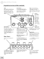
A quick overview of the controls
Sizzle
Adds “punch” and “air” to
the signal, especially useful
for bass sounds. It puts a
high-pass filter before the
compressor’s detector, and
adds a bit of HF EQ on the
output.
16
Look Ahead
Looks at the digital signal
several milliseconds before it
is processed, to anticipate
peaks. Reduces the attack
time to less than zero.
Type selects the kind of
compression the Smashup
will emulate. Several
different analog compression
types are modeled. See page
30.
Release
determines
how quickly
the
compressor
will “let go”
of the signal
after levels
have fallen
below the
threshold.
Turn counterclockwise for
faster releases.
Threshold sets
the level where
the compressor starts
working on the signal. At the
“5 o’clock” setting, the
threshold is high and there’s
no compression; turn
counter-clockwise for more
compression (and less
output).
Attack sets how much time
will pass after a peak is
detected before the signal is
compressed. Turn clockwise
to let more attack through,
counter-clockwise to
compress all peaks.
Rear Panel
BYPASS lets signal pass
through without any
compression.
Output
increases the
output level.
Use this to increase the signal
to normal levels after it has
been compressed.
Signal LED
When this lights green, the
Smashup is getting an input
signal. When it’s red, it’s
seeing too much level...so
turn down the instrument...
Plug the power adapter in
here.
The FOOT SWITCH may be
connected to any momentary
pedal, to engage the BYPASS
function.
...or the TRIM control here
on the back panel.
The ModLink connectors let
you arrange several ModFX
units in a chain, without
having to use input and
output cables inside the
chain.
INPUTS and OUTPUTS are
standard 1/4” line-level
jacks.
If you’re using a ModLink
chain, you only need to
connect to the first unit’s
input, and the last unit’s
output.
2 Connections
Unpacking and Inspection
Your Smashup was packed carefully at the factory. The shipping
carton was designed to protect the unit during shipping. Please
retain this container in the highly unlikely event that you need to
return the Smashup for servicing.
The shipping carton should contain the following items:
•
•
•
Smashup with the same serial number as shown on the
shipping carton
Power Adapter
This instruction manual
To register your purchase, go to the Alesis website at
www.alesis.com.
Installing in a Rack
The Smashup is designed for tabletop use, but can also be installed
in a standard 19" audio equipment rack. For rack mounting,
contact your Alesis dealer for the ModFX Rack. This rack shelf
holds three ModFX units in a 3-space high 19” rack.
Power
The Smashup comes with an AC power adapter that transforms
the voltage from a standard outlet into 9 volts AC (830 mA).
Plug the small end of the power adapter cord into the Smashup’s
POWER INPUT socket and then plug the adapter itself into a
good quality, noise-free AC power source of the proper rating.
The supplied AC line adapter is designed only for the destination
to which the unit is shipped. To use the Smashup in another
country, contact your Alesis dealer for an Alesis P3 adapter
suitable for the electrical system in the country you are traveling
to.
Make sure you read the
initial Important Safety
Instructions chapter at the
front of this manual.
Avoid “popping”:
Don’t plug the power adapter
into the Smashup until all
other audio cables have been
hooked up. Make sure your
amplifier or powered
speakers are switched off
when plugging in the
Smashup to avoid damage.
17
2
Connections
Connecting audio
The Smashup will work in many different applications, whether
you are connecting an instrument directly into it, or connecting it
through a mixing console. But since the Smashup is a stereo
effect unit, it’s important to know whether the source will be
stereo or mono.
In-line connection
If you’re connecting a keyboard, guitar or bass directly to the
Smashup, hook it up this way:
1. Connect a 1/4" phone cord to the [LEFT/MONO] INPUT
of the Smashup from the instrument.
2. Connect another 1/4" phone cord from the LEFT OUTPUT
of the Smashup to an amplification system or mixer input.
3. If the instrument and amp or mixer is stereo, connect a
second pair of 1/4" phone cords from the instrument to the
RIGHT INPUT of the Smashup, and connect the RIGHT
OUTPUT of the Smashup to the other input of the stereo
amplification system, or the next mixer input.
4. If you’re connecting directly to a stereo mixer, pan the two
channels hard left and hard right to get the maximum effect.
18
When connecting audio
cables and/or turning power
on and off, make sure that all
devices in your system are
turned off and the volume
controls are turned down.
Turn up the trim...
Most guitars and basses have
relatively low output levels.
For the quietest effect, turn
up the volume on the guitar to
full, then crank up the
[TRIM] control on the back
of the Smashup until the
SIGNAL LED on its top panel
flashes red while you play,
then back it off a bit.
Connections
2
Connecting to the Channel Inserts of a
mixing console:
Most recording consoles have a jack in each channel near the mic
and line inputs labeled "Insert". This is typically a TRS jack with
the send and return on the same jack. To use the Smashup as a
channel insert, you will need an insert cable (not included).
Ring:
Insert return
Tip:
Insert send
Sleeve:
Insert Ground
Insert SEND:
To ModFX INPUT
Insert RETURN:
From ModFX OUTPUT
This cable splits the TRS insert jack into two unbalanced mono
connectors. Usually, the tip is connected to the INPUT of the
Smashup and the ring is connected to the OUTPUT of the
Smashup. However, this may be reversed on some recording
consoles. Check your mixer’s Reference Manual to be sure or just
try it both ways – this won’t damage the Smashup.
For stereo operation, you would use two insert cables, inserted
into two adjacent channels of the mixer. One would send and
receive signal to the left channel of the Smashup, and the pan pot
of that mixer channel would normally be panned to the left. Pan
the next mixer channel, for the right side of the Smashup, to the
right.
19
2
Connections
Connecting to the Main Outputs of a mixing
console:
In addition to channel inserts, most mixing consoles have main
insert jacks near the main outputs. You can use insert cables to
connect the Smashup to the main L/R bus the same way you
connect it to a pair of channels. Simply connect one insert cable
to the left main insert of the mixer, and connect the two mono
jacks to the left INPUT and OUTPUT of the Smashup. Use
another insert cable to connect the right main insert to the right
INPUT and OUTPUT of the Smashup.
Alternatively, you could plug the mixing console’s main outputs
directly into the Smashup’s inputs, then feed the Smashup’s
outputs to your monitor amps or mixdown recorder. However,
with this method if you fade down the volume at the end of the
song, the sound quality will change as you fade, since the signal
will fall below the threshold setting. That’s why it’s better to use
insert jacks, if they’re available.
Don’t connect the
Smashup into an
effect send/return loop
Unlike most effects,
compression is NOT designed
to be “added” to a signal—it
acts on the entire level going
through it.
Connecting to the inserts on an instrument
amplifier:
The insert send on a guitar or bass amp is usually labeled "effects
send and return" or "insert send and return". This allows you
to preamplify your instrument before compressing it and
sending it to the power amp.
Most guitar amps are single channel, so connect a single insert
cable from the amp to the LEFT INPUT and LEFT OUTPUT of
the Smashup. Some amps have separate “effect send” and “effect
return” jacks; for these, use standard cables. Check the manual of
your amplifier for details.
If you are using a dedicated rack-mount preamplifier, another
method would be to insert the Smashup between the preamp and
the input(s) of the power amp.
20
Never connect the
Smashup between the
power amp and the
speaker!
The high power levels created
by the power amp will
destroy the circuitry of the
Smashup.
Connections
2
Connecting to equipment with XLR inputs
and outputs:
If you are connecting the Smashup to a product with XLR
balanced inputs and outputs, you will need to convert this signal to
a 1/4” unbalanced connector. Make sure that Pin 2 of the XLR
connector is connected to the Tip of the 1/4” adapter or cable.
Watch out for high levels, however: some XLR sources put out
levels close to the maximum the Smashup can accept (about +12
dBu) even when its trim is at minimum. Lower the level of the
source if the [SIGNAL] LED flashes red.
About audio cables
The connections between the Smashup and your studio are your
music’s lifeline, so use only high quality cables. These should be
low-capacitance shielded cables with a stranded (not solid) internal
conductor and a low-resistance shield. Although quality cables
cost more, they do make a difference.
Don't use line
transformers:
Many XLR-to-1/4" adapters
sold at electronics stores are
NOT adapters, but
transformers (and very low
quality transformers at that).
Don't use these on the output
of the Smashup—they're
unnecessary and generally
sound awful because they
don't have the headroom to
handle the Smashup's output.
Get a hard-wired adapter or
cable from your professional
audio dealer, or make one
yourself from components.
Route cables to the Smashup correctly by observing the following
precautions:
•
Do not bundle audio cables with AC power cords.
•
Avoid running audio cables near sources of
electromagnetic interference such as transformers,
monitors, computers, etc.
•
Do not place cables where they can be stepped on.
Stepping on a cable may not cause immediate damage,
but it can compress the insulation between the center
conductor and shield (degrading performance) or reduce
the cable’s reliability.
•
Avoid twisting the cable or having it make sharp, right
angle turns.
•
Never unplug a cable by pulling on the wire itself.
Always unplug by firmly grasping the body of the plug
and pulling directly outward.
21
2
Connections
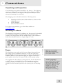
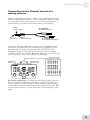
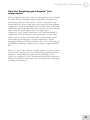
Using the ModLink
The Smashup can be connected to other effect boxes in the
ModFX family via the ModLink. The ModLink is a cable-free
connection between two ModFX units that transfers digital audio
and word clock. The 9-pin male connector on the left side of the
unit is the ModLink IN port. The 9-pin female connector on the
right side is the ModLink OUT port. By directly connecting two
ModFX units via the ModLink, audio will pass from the left-most
unit to the right-most unit.
Inputs
Master
AC adapter
Outputs
First Slave
Second Slave
Audio Flow
The audio signal flows from left to right. The Master will send its
digital audio output to the First Slave, and the First Slave will, in
turn, send its output to the Second Slave.
22
What about the input
and output jacks on
the slave units?
When a unit is a slave to
another unit, its audio input
jacks are disabled; it will get
its audio input digitally from
its ModLink port. The output
jacks, however, are always
active; so an audio output
can be tapped from any
linked unit, without
interrupting the flow to the
rest of the chain.
3 Using the Smashup
This section defines compression, and explains the functions of
the Smashup’s controls in greater detail.
What is a compressor?
Most types of signal processors, such as reverbs, phaser/flangers,
and equalizers, make an obvious change in the sound. But a
compressor's action is much more subtle; when used properly,
many listeners won't be aware that signal processing is being used.
Yet, compressors are essential in modern audio work to make
instruments hold their place in the mix, and add sustain and body.
Almost every lead vocal on a pop record is compressed during
tracking or mixdown. Often the entire stereo mix is compressed
or limited during the mastering process.
A compressor/limiter like the Smashup is essentially an automatic
volume control. Imagine an engineer with his hand on a fader and
his eyes on an input level meter. As long as the meter stays below
a certain point (the threshold), he leaves the fader up and the gain
is unchanged. But the instant the sound gets louder, the engineer
pulls down the fader by a certain amount. After the sound gets
soft again, the engineer will push the fader back up. That's what
the Smashup is doing, except much faster and more accurately
than humanly possible.
Paradoxically, by cutting the peak levels, the Smashup allows you
to raise the average level of a sound using the [OUTPUT] control
and make the overall sound louder. By coordinating the
[THRESHOLD] and [OUTPUT] controls, you can set a stable
sound that will hold its position in the mix regardless of the
dynamics of the instrument or vocal. Compression is the tool to
use when you want a lead vocal to go from a scream to a whisper
and not get buried behind the instruments.
23
3
Using the Smashup
What the controls do
Let's go back to the "engineer with his hand on a fader and eyes
on the meter" analogy. The top panel controls simply tell the
"engineer" what rules he should follow. [THRESHOLD] tells him
how high the input level can rise before he has to start pulling
down the fader: if it's turned full clockwise, he won't pull down
his fader at all; if it's turned full counter-clockwise, he'll have his
hand on the fader even for very faint sounds.
How far does he pull the level down? That depends on the
[TYPE] setting, as will be explained later. For example, in Classic
mode, Smashup acts as a compressor/limiter with a ratio of 4:1.
That means that if the input rises above the threshold by 8
decibels, the output will only be allowed to rise 2 decibels. In
Transparent mode, the compression ratio is a gentler 2:1, so an
input 8 dB above the threshold will be allowed to rise 4 dB. In
most modes, the detector of the Smashup looks at peak levels, not
the average level of the signal. In addition, each compressor has
its own “knee” characteristic (hard or soft). Soft-knee
compressors allow signal levels near the threshold to be
compressed more gradually.
The [ATTACK] and [RELEASE] controls involve the speed of the
engineer's response, as does the [LOOK AHEAD] switch. Short
attack times may order the engineer to pull down the fader
1/10,000th of a second after he sees a too-loud signal; long attack
times tell him to let transients less than about 1/5th of a second
pass. [RELEASE] tells the engineer how quickly he should push
the fader back up again after a loud signal has stopped; when it's
turned counter-clockwise, he pushes the fader back up instantly,
and when it's full clockwise, he may take take a few hundred
milliseconds to push his fader back up to unity gain.
The [OUTPUT] control is simply a gain control located after our
"automatic engineer in the box". Since the engineer will pull the
fader down when he “sees” levels above the [THRESHOLD]
setting, it’s up to you to compensate for that action by raising the
output level, if that’s necessary to restore the average level after the
peaks have been removed.
The most important controls are the [THRESHOLD] and
[OUTPUT] knobs. They both interact to get the effect you want,
and that requires some experimenting.
24
Attack/Release times
vary by Type
In fact, each Type has its own
Attack/Release behavior and
time ranges.
Using the Smashup
3
How the Smashup goes beyond “just
compression”
Having explained what the controls are designed to do, you should
be aware that the Smashup’s digital compression algorithms do
much more than just control levels. Just as a tube guitar amp
sounds different from a solid-state power amp, the most popular
compressors sound notably different from each other, even when
their attack, threshold, ratio and release controls are set exactly the
same. And, like guitar amps, there’s no single “best”
compressor...good studios often have 6 or 7 different brands of
compressor in the rack because some are better on rock vocals,
others are best on bass, still others offer a unique drum sound.
Alesis analyzed the behavior of many compressors, and the
Smashup’s different [TYPE] settings are the result. You really get
six different-sounding compressors in a single, compact ModFX
box.
There’s no way to describe the complete behavior of each control
in each mode. Just be aware that a particular [ATTACK] setting
will have a totally different result when the [TYPE] is set to
OPTO, as compared to FAT. Experiment with all the settings on
different instruments and vocals, and you’ll find some really greatsounding combinations.
25
3
Using the Smashup
Operational advice
Gain structure
Extreme settings will lead to extreme results. If you turn the
threshold down all the way, the Smashup will do what it's being
told to do: turn the level way down. If you then try to
compensate by cranking the [OUTPUT] control to its maximum,
you'll amplify the noise of your source and the Smashup itself.
The noise will fade itself in whenever the input signal stops,
resulting in the classic "pumping" and "breathing" problems.
Noise is present in every system, and improper use of any
compressor will amplify it to an obnoxious level.
For low noise operation, make sure your mixer, Smashup,
and amplifier settings are set properly. As a general rule, you
want as much gain as possible in the front of the system (at the
instrument or microphone preamp), so that a good line-level signal
is travelling through the whole signal path. If you have a weak
signal to start with, and then amplify it at the end of the signal path
(by turning the main outputs of the mixer all the way up, for
example) it will be excessively noisy.
When using a compressor on a live P.A. system, improper settings
can cause feedback. Make sure that a channel is well below the
feedback point when there is no gain reduction active. If you hear
feedback every time the music stops, you must lower the overall
level of the system.
Setting Levels
Proper setting of the output levels is crucial in order to achieve the
maximum signal-to-noise ratio. As a good rule of thumb, it is
usually best to first set the [OUTPUT] level control at 12 o’clock
or 50%. Then, press the [BYPASS] button in and out while
listening to signal through the unit. Turn the [OUTPUT] level up
or down so that the output level is roughly the same whether the
unit is bypassed or compressing.
About stereo compression
The Smashup is, in fact, two separate compressor channels joined
by one set of controls. The detectors of the two channels are
linked. This means that if the left channel's signal rises above the
threshold, the right channel's gain will be reduced by the same
amount as the left channel, and vice versa. This keeps the stereo
image from wandering from left to right when compressing a
stereo mix.
26
Using the Smashup
3
Description of Controls
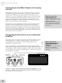
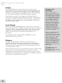
Threshold
The [THRESHOLD] knob sets the level where compression will
begin. As long as the input signal level is below the Threshold
level, the Smashup will do nothing to the signal. Once the input
signal crosses the Threshold, the Smashup will begin compressing
(turning down the level).
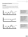
Graph of input level
Threshold
This shows the level of an
input to the Smashup. The
dotted line represents the
[THRESHOLD] level.
Graph of compression
0 dB
This shows the Smashup’s
internal gain setting, with the
solid line meaning “no
reduction” for most of the
graph above. (This assumes
the [ATTACK] and
[RELEASE] knobs are set
fast enough to track the input
this closely).
Graph of output level
Threshold
This is what the output will
sound like—the third peak in
the signal has been
“smashed” from its original
level.
27
3
Using the Smashup
Attack
The [ATTACK] knob controls the amount of time before
compression starts. The range of this control is generally in the
range from 0.1 (full counter-clockwise) to 300 milliseconds; but
this may vary depending on the [TYPE] setting. [ATTACK] has
no effect when the [LOOK AHEAD] switch is engaged.
Long attacks are useful for keeping the initial transients of
percussive sounds like drums, lead guitar, and bass. Short attacks
are good for melodic parts like vocals and strings. Experiment
with different short attack times on snare drums to get more or
less of the “stick” attack.
Look Ahead
When the [LOOK AHEAD] switch is turned on, a very small
amount of delay (under 3 milliseconds, about the time sound takes
to travel 3 feet) is introduced in the signal. The detector of the
compressor looks at the peak levels in this delay, so it can “preattack” or lower its gain even before the peak arrives for
processing.
For obvious reasons, when [LOOK AHEAD] is on, the
[ATTACK] knob has no effect.
Release
The [RELEASE] knob controls the amount of time the
compressor takes to stop compressing after the signal crosses
under the threshold. The range of this control is very different
from type to type, but in every case the longest release time is at
the full clockwise rotation.
Short release times are good for percussive, punchy sounds; longer
release times can make compression less obvious on vocals.
Adjusting the release time may be necessary when using extreme
compression and “pumping” or “breathing” is audible, or if lowerlevel signals are getting lost after peaks.
28
Pumping and
Breathing
When a compressor is
making large changes to the
input signal (10 to 12 dB or
more) the noise floor will also
rise and fall with the signal
level. When this noise signal
rises and falls drastically
between signals, such as a
heavily compressed, noisy
drum track, you might hear
the noise level “breathing”
between drum hits. One
solution to this breathing
problem is to turn up the
release time. This way, the
noise floor won’t have time to
rise between drum hits.
However, if the Release time
is too long, lower level
signals after the peak will be
lost as the compressor slowly
stops reducing gain. This is
called “pumping” as the
lower level signals (noise
included) slowly fade back up
to their normal signal level.
The secret to avoiding these
problems is to achieve a
balanced release time on the
input signal.
The PUMP mode of the
Smashup is set up
intentionally to use pumping
as a creative tool.
Using the Smashup
3
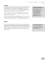
Output
The [OUTPUT] knob controls the level of the Smashup’s output.
The Output control is useful for making up level that was lost
during compression, or matching the input level of a mixer or
recorder. The unity gain setting of the [OUTPUT] knob (the level
where input level = output level when [THRESHOLD] is set to
the maximum) is around the “12 o’clock” position.
Set the output low enough to avoid clipping the output (unless
that’s the sound you’re going for), and high enough so there’s a
good signal-to-noise ratio.
This control is disabled if the [BYPASS] button is pressed. If you
get approximately the same level when Bypass is on as when it is
off, that’s generally a good place for the [OUTPUT] knob to sit.
Intentional clipping: The
output drivers of some classic
analog compressors have
unique “soft clip”
characteristics that enhance
the tone of the signal.
Certain TYPE settings
emulate this output
overdriving when you
deliberately raise the
[OUTPUT] control above
unity gain. Try it!
Sizzle
This button adds brightness and punch to the signal, avoiding the
“dull” sound that compression sometimes brings. [SIZZLE] is
especially good for electric bass and drums. Technically speaking,
[SIZZLE] does two things: adds a little high frequency EQ on the
output to brighten things up, and puts a 120 Hz high-pass filter
before the compressor’s detector so strong bass notes won’t be
compressed.
FAT mode and Sizzle
The FAT mode starts out
“pre-sizzled”, and pressing
[SIZZLE] adds even more
bottom and high end.
29
3
Using the Smashup
Type Select Switch
The up/down [TYPE] rocker switch on the right side of the unit
selects the type of compression used by the Smashup. The LEDs
next to the switch light up to indicate the current Type.
The Smashup contains six different compression styles. Some are
modeled after the operation of classic analog compressor/limiters,
and others are totally unique. Each Type has its own unique sound
and effect on the other controls, though the differences may be
subtle at first.
Each Type has its own compression ratio (the amount of gain
reduction applied when a signal rises above the threshold), hard
knee/soft knee setting, detector characteristics, attack and release
curves, and distortion characteristics. These have been carefully
developed to give you the most useful compressor sounds, without
having to set eight different controls.
There’s no way to adequately describe all the characteristics of the
complex digital compression algorithms developed by Alesis
engineers, so after you’ve read the following descriptions be sure
to try each one with several different audio sources:
Classic
This is the standard VCA-style compressor sound, as found in
classic units like the dbx™ 160. The compression ratio is 4:1, but
it has a very soft knee setting and a slightly nonlinear release.
Classic mode is great for taking the peaks out of vocals with a fast
attack, or to get a clean sustain on guitar or bass while still
preserving some dynamics.
Opto
The first compressors regulated the audio level by using an optical
system. A light got brighter at higher input levels, and this light
shone on a photoresistor that reduced the output level. The most
famous of these devices, the Tektronix™ LA-2A, is still a prized
possession of many studios. Optical compressors have a very
particular sound to them. Because the lamp filament takes a
moment to get to full brightness, they naturally have a slower
attack than other compressors. In OPTO mode, the Smashup
emulates the sound of these units. In particular, the attack time is
not as quick as in other types, even at the minimum setting. The
ratio is 6:1 with a soft knee setting; it is useful for classic vocals
and drum sounds.
Transparent
When you want compression without any side effects, use
TRANSPARENT mode. In this mode, the compression ratio is a
more subtle 2:1 with a soft knee, and it emulates a clean, solid-state
output driver circuit with no coloration. Even at extremely low
settings of [THRESHOLD], gain isn’t reduced as much as it is in
other types.
30
Using the Smashup
3
De-Ess
De-essing is commonly used to process voices where the “s”
sound and other sibilants are too loud and distracting. By telling
the compressor to be extra sensitive to a certain range of
frequencies, the “s” sound can be almost completely removed
from a voice. The ratio is 8:1 with a soft knee, but because the
detector is listening most closely to 4.5 kHz, the resulting sound is
still relatively transparent.
Pump
On the other hand, PUMP is designed to emulate a limiter
deliberately overdriven to provide creative processing. With a
100:1 compression ratio and a hard knee, the [THRESHOLD] sets
a wall that the input signal can’t rise above. The PUMP type has
some secret ingredients that are especially suited for extreme guitar
and drum processing. On drums, adjust the [ATTACK] and
[RELEASE] controls properly, and you’ll make a polyrhythm out
of the resulting pumping sound. Note that even at full counterclockwise, the [RELEASE] setting is still relatively short; though
the release times will vary according to the [THRESHOLD] setting
automatically.
In many standard
compressors, a “detector
loop” is included. By placing
an equalizer in this loop with
a boost at around 4 kHz, the
detector will be more
sensitive to the “s” sounds in
that range. Note that the tone
of the signal doesn’t
change—it will just compress
the signal when the high
frequency content rises above
the threshold.
Fat
FAT is a close relative of PUMP, but designed for extra bottom
end. This is another heavy compression type with an infinite ratio,
but has a softer knee than PUMP. The most important
characteristic of FAT is that it won’t compress the bottom end as
much, and adds a little high end EQ for brightness. Pressing
[SIZZLE] doubles this effect.
31
3
Using the Smashup
Bypass
This button sends the signal directly from the input to the output
without any compression. Press [BYPASS] to check the sound of
the source without any effect from the Smashup. When the red
BYPASS LED is lit, the compressor is off. The Bypass function
can also be activated by the foot switch.
Since the Smashup is a digital effect, signal always passes through
the digital A/D–D/A conversion process, so that digital signal will
flow through to other effects in a ModLink chain even when
[BYPASS] is on. So, unlike old analog effects, this is not a
“hardwire” bypass switch—the Smashup must be powered on to
pass signal through, even in bypass mode. Similarly, the [TRIM]
control is always active, since it’s an analog control regulating the
level feeding the analog-to-digital converters.
Using the Foot Switch
If you need to bypass the effect totally but your hands aren’t free,
simply connect any momentary footswitch (such as those used for
keyboard sustain pedals, either NC normally closed or NO
normally open) to the [FOOT SWITCH] jack on the rear panel.
The footswitch will turn the BYPASS LED on and off.
32
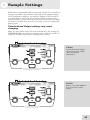
4 Sample Settings
While there’s nothing like discovering new sounds for yourself, we
thought it would be a good idea to provide some sample settings
of the Smashup to help get you started. Simply set the knobs on
your Smashup so they’re at the positions shown, and press the
rocker switches so each effect is in the mode shown by the LEDs.
Feel free to modify these any way you want to suit your particular
playing style.
Threshold and Output settings may need
changing
Since we don’t know how loud your instrument is, the settings of
[THRESHOLD] can only be a starting point. (They’re shown for
a typical –10 dBV signal with an average crest factor.)
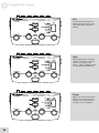
Classic
A good all-around setting;
the slow attack lets a little
“bite” through on
instruments.
De-Ess
If there’s too much sibilance
in a vocal track, try this
setting.
33
4
Sample Settings
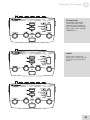
Fat
Try this on any instrument
that needs a strong low end,
especially basses and kick
drums.
Opto
This duplicates the sound of
optical compressors used in
classic recordings (and
today). This is equally useful
on vocals and instruments.
Pump
When you want compression
taken to its extreme, try this
setting It’s compression as
an effect, not a technique.
34
Sample Settings
4
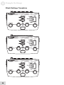
Transparent
This setting will provide
consistent compression
without calling attention to
itself. Note that [ATTACK]
has no effect, since [LOOK
AHEAD] is on.
Blank
Fill in your own favorite
settings here. Photocopy the
next page if you need more
space.
35
4
Sample Settings
Blank Settings Templates
36
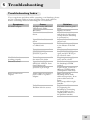
5 Troubleshooting
Troubleshooting Index
If you experience problems while operating your Smashup, please
use the following table to locate possible causes and solutions
before contacting Alesis Product Support for assistance.
Symptoms
No audio outputs.
Cause
No input audio (SIGNAL
LED doesn’t flash).
Bad cables.
Destination is turned
down.
Input Trim knob is turned
down
Input cables are connected
to a linked unit
Power is not connected
[THRESHOLD] or
[OUTPUT] set low
ModLinked units are not
working properly
Distorted sound
Power dropout to one of
the units in the chain
Input level too high
(SIGNAL LED on front
panel flashes red)
[OUTPUT] is set high
Buzz or hum from
outputs
Audio cables are crossing a
power cable or a power
adapter.
Bad cables
Problem with the source
Solution
Test with a known good
input.
Replace the cables.
Check the connections
and the level of the mixer
or amp that the Smashup
is connected to.
Adjust the knob to the
proper level.
Connect the input cables
to the Master of the link
chain
Go take a walk
Set [THRESHOLD] wide
open, and [OUTPUT] to
12 o’clock to start
Plug in a power supply to
every unit in a chain.
Turn down the source, or
the Smashup’s TRIM
control
Turn it down, or choose a
different [TYPE] setting
(Transparent or De-Ess)
Make sure that the
Smashup and its audio
cables are kept away from
power cables and wall
warts.
Don’t wrap cable in tight
bundles.
Replace the cables
Try bypassing the
Smashup by connecting
the input cables to the
output cables and see if
the problem remains.
37
5
Troubleshooting
Symptoms
AC hum
38
Cause
Ground loop
Solution
Place all equipment in the
studio on a common
ground (see next page)
Troubleshooting
5
Avoiding ground loop noise
In today’s studio, where it seems every piece of equipment has its
own computer chip inside, there are many opportunities for
ground loop problems to occur. These show up as hums, buzzes
or sometimes radio reception and can occur if a piece of
equipment "sees" two or more different paths to ground. While
there are methods to virtually eliminate ground loops and stray
radio frequency interference, most of the professional methods are
expensive and involve installing a separate power source just for
the sound system. Alternatively, here are some helpful hints that
professional studio installers use to keep those stray hums and
buzzes to a minimum.
KEEP ALL ELECTRONICS OF THE SOUND
SYSTEM ON THE SAME AC ELECTRICAL
CIRCUIT.
Most stray hums and buzzes happen as a result of different parts
of the sound system being plugged into outlets of different AC
circuits. If any noise generating devices such as air conditioners,
refrigerators, neon lights, etc., are already plugged into one of these
circuits, you then have a perfect condition for stray buzzes. Since
most electronic devices of a sound system don’t require a lot of
current (except for power amplifiers), it’s usually safe to run a
multi-outlet box or two from a SINGLE wall outlet and plug in all
of the components of your system there.
KEEP AUDIO WIRING AS FAR AWAY FROM AC
WIRING AS POSSIBLE.
Many hums come from audio cabling being too near AC wiring.
If a hum occurs, try moving the audio wiring around to see if the
hum ceases or diminishes. If it’s not possible to separate the audio
and AC wiring in some instances, make sure that the audio wires
don’t run parallel to any AC wire (they should only cross at right
angles, if possible).
TO ELIMINATE HUM IF THE ABOVE HAS FAILED:
1.
Disconnect the power from all outboard devices and
tape machines except for the Smashup, the mixer and
control room monitor power amp.
2.
Plug in each tape machine and outboard effects device
one at a time. If possible, flip the polarity of the plug of
each device (turn it around in the socket) until the
quietest position is found.
3.
Make sure that all of the audio cables are in good
working order. Cables with a detached ground wire will
cause a very loud hum!!
39
5
Troubleshooting
4.
Keep all cables as short as possible, especially in
unbalanced circuits.
If the basic experiments don’t uncover the source of the problem,
consult your dealer or technician trained in proper studio
grounding techniques. In some cases, a "star grounding" scheme
must be used, with the mixer at the center of the star providing the
shield ground on telescoping shields, which do NOT connect to
the chassis ground of other equipment in the system.
Line conditioners and spike protectors
Although the Smashup is designed to tolerate typical voltage
variations, in today’s world the voltage coming from the AC line
may contain spikes or transients. These can cause audible noises,
and they can stress your gear and, over time, possibly cause a
failure. There are three main ways to protect against this, listed in
ascending order of cost and complexity:
40
•
Line spike/surge protectors. Relatively inexpensive,
these are designed to protect against strong surges and
spikes, acting somewhat like fuses in that they need to
be replaced if they’ve been hit by an extremely strong
spike.
•
Line filters. These generally combine spike/surge
protection with filters that remove some line noise
(dimmer hash, transients from other appliances, etc.). A
good example is the Isobar™ series from Tripp Lite.
•
Uninterruptible power supply (UPS). This is the
most sophisticated option. A UPS provides power even
if the AC power line fails completely. Intended for
computer applications, a UPS allows you to complete an
orderly shutdown of a computer system in the event of a
power outage. In addition, the isolation it provides
from the power line minimizes all forms of
interference—spikes, noise, etc.
Troubleshooting
5
Care and Maintenance
Cleaning
Disconnect the AC cord, then use a damp cloth to clean the
Smashup’s metal and plastic surfaces. For heavy dirt, use a nonabrasive household cleaner such as Formula 409™ or Fantastik™.
DO NOT SPRAY THE CLEANER DIRECTLY ONTO THE
FRONT OF THE UNIT AS IT MAY DESTROY THE
LUBRICANTS USED IN THE SWITCHES AND CONTROLS!
Spray onto a cloth, then use cloth to clean the unit.
Refer all servicing to Alesis
We believe that the Smashup is one of the best signal processors
that can be made using current technology, and should provide
years of trouble-free use. However, should problems occur, DO
NOT attempt to service the unit yourself unless you have training
and experience. Service on this product should be performed only
by qualified technicians. NO USER-SERVICEABLE PARTS
INSIDE.
41
5
Troubleshooting
Obtaining repair service
Before contacting Alesis, check over all your connections, and
make sure you’ve read the manual.
Customers in the USA and Canada:
If the problem persists, contact Alesis and request the Product
Support department. Make sure you have the unit’s serial number
with you. Talk the problem over with one of our technicians; if
necessary, you will be given a return order (RO) number and
instructions on how to return the unit. All units must be shipped
prepaid and COD shipments will not be accepted.
For prompt service, indicate the RO number on the shipping label.
Units without an RO will not be accepted. If you do not have
the original packing, ship the unit in a sturdy carton, with shockabsorbing materials such as Styrofoam pellets (the kind without
CFCs, please) or "bubble-pack" surrounding the unit. Shipping
damage caused by inadequate packing is not covered by the Alesis
warranty.
Tape a note to the top of the unit describing the problem, include
your name and a phone number where Alesis can contact you if
necessary, as well as instructions on where you want the product
returned. Alesis will pay for standard one-way shipping back to
you on any repair covered under the terms of this warranty. Field
repairs are not authorized during the warranty period, and repair
attempts by unqualified personnel may invalidate the warranty.
Customers outside the USA and Canada:
Contact your local Alesis distributor for any warranty assistance.
The Alesis Limited Warranty applies only to products sold to users
in the USA and Canada. Customers outside of the USA and
Canada are not covered by this Limited Warranty and may or may
not be covered by an independent distributor warranty in the
country of sale. Do not return products to the factory unless you
have been given specific instructions to do so.
42
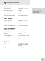
Specifications
Audio Input
Input Connectors:
2 unbalanced 1/4” jacks
Maximum Input Level:
+10 dBV
Nominal Level:
-10 dBV
Input Impedance:
470kΩ
Input Converter Resolution:
24-bit, 48 kHz sampling
All measurements done over
a 22Hz – 22kHz range with a
1kHz sine wave at -1dBFS
input. Impedances are
measured at 1kHz.
Audio Output
Output Connectors:
2 unbalanced 1/4” jacks
Maximum Output Level:
+9 dBV
Output Impedance:
500Ω
Output Converter Resolution:
24-bit, 48 kHz sampling
Audio Performance
(Analog In to Analog Out)
Signal To Noise Ratio:
>100 dB A-weighted
THD+N:
< 0.005%
Frequency Response:
± 1dB from 22Hz to 22kHz
Internal DSP Resolution:
28-bit
Power Consumption:
7 Watts max (9VAC Alesis P3)
Mechanical
Size:
2.1” H x 5.8” W x 3.9” D
(53mm H x 148mm W x
98mm D)
Weight:
12.6oz. (357 g)
43
6
Specifications
This page intentionally left blank.
44
Index
amplifier, 20
Attack, 16, 24, 28
BYPASS, 16, 32
with foot switch, 32
cables, 21
Classic, 24, 30
clipping, 29
compression
defined, 23
compression ratio, 30
defined, 24
De-Ess, 31
digital converters, 32, 43
digital signal processing, 4
DSP, 43
Fat, 31
feedback, 26
FOOT SWITCH, 16, 32
Ground Loop, 39
grounding, 7
guitar, 18
hard knee/soft knee, 30
Hums and buzzes, 39
INPUTS, 15
INPUTS and OUTPUTS,
16
Insert Cables, 19
knee, 24
levels, 21, 26
Look Ahead, 16, 24, 28
mixing console
hookup, 20
ModFX, 4, 22
ModLink, 4, 16, 22
and Bypass, 32
noise, 26
Opto, 30
Output, 23
knob, 16
knob, 24, 29
OUTPUTS, 15
on ModLink slave units, 22
power adapter, 17
Power cable, 7
Pump, 31
pumping and breathing, 26, 28
Rack mounting, 17
Release, 16, 24, 28
Safety, 7
SIGNAL LED, 15, 16, 18, 21
Sizzle, 16, 29
stereo, 18, 19, 26
Threshold, 16, 23, 24, 27
transformers, 21
Transparent, 24, 30
TRIM, 15, 16, 18
active in bypass mode, 32
Type, 16, 24, 25
Type Select Switch, 30
XLR, 21
45
Warranty / Contact Alesis
Alesis Limited Warranty
ALESIS CORPORATION ("ALESIS") warrants this product to be free of defects
in material and workmanship for a period of one (1) year for parts and for a period of
one (1) year for labor from the date of original retail purchase. This warranty is
enforceable only by the original retail purchaser and cannot be transferred or assigned.
For the most effective service, the purchaser should register the purchase on the
ALESIS website at http://www.alesis.com/support/warranty.htm.
During the warranty period ALESIS shall, at its sole and absolute option, either repair
or replace free of charge any product that proves to be defective on inspection by
ALESIS or its authorized service representative. In all cases disputes concerning this
warranty shall be resolved as prescribed by law.
To obtain warranty service, the purchaser must first call or write ALESIS at the
address and telephone number available on the Alesis Website to obtain a Return
Authorization Number and instructions concerning where to return the unit for
service. All inquiries must be accompanied by a description of the problem. All
authorized returns must be sent to ALESIS or an authorized ALESIS repair facility
postage prepaid, insured and properly packaged. Proof of purchase must be
presented in the form of a bill of sale, canceled check or some other positive proof
that the product is within the warranty period. ALESIS reserves the right to update
any unit returned for repair. ALESIS reserves the right to change or improve design
of the product at any time without prior notice.
This warranty does not cover claims for damage due to abuse, neglect, alteration or
attempted repair by unauthorized personnel, and is limited to failures arising during
normal use that are due to defects in material or workmanship in the product.
THE ABOVE WARRANTIES ARE IN LIEU OF ANY OTHER
WARRANTIES OR REPRESENTATIONS WHETHER EXPRESS OR
IMPLIED OR OTHERWISE, WITH RESPECT TO THE PRODUCT, AND
SPECIFICALLY EXCLUDE ANY IMPLIED WARRANTIES OF FITNESS
FOR A PARTICULAR PURPOSE OR MERCHANTABILITY OR OTHER
IMPLIED WARRANTIES. Some states do not allow limitations on how long an
implied warranty lasts, so the above limitation may not apply to you.
IN NO EVENT WILL ALESIS BE LIABLE FOR INCIDENTAL,
CONSEQUENTIAL, INDIRECT OR OTHER DAMAGES RESULTING
FROM THE BREACH OF ANY EXPRESS OR IMPLIED WARRANTY,
INCLUDING, AMONG OTHER THINGS, DAMAGE TO PROPERTY,
DAMAGE BASED ON INCONVENIENCE OR ON LOSS OF USE OF THE
PRODUCT, AND, TO THE EXTENT PERMITTED BY LAW, DAMAGES
FOR PERSONAL INJURY. Some states do not allow the exclusion or limitation of
incidental or consequential damages, so the above limitation or exclusion may not
apply to you.
THIS CONTRACT SHALL BE GOVERNED BY THE INTERNAL LAWS
OF THE STATE OF CALIFORNIA WITHOUT REFERENCE TO
CONFLICTS OF LAWS. This warranty gives you specific legal rights, and you may
also have other rights required by law which vary from state to state.
This warranty only applies to products sold to purchasers in the United States of
America or Canada. The terms of this warranty and any obligations of Alesis under
this warranty shall apply only within the country of sale. Without limiting the
foregoing, repairs under this warranty shall be made only by a duly authorized Alesis
service representative in the country of sale. For warranty information in all other
countries please refer to your local distributor.
46
For more effective
service and product
update notices, please
register your Smashup
online at:
http://www.alesis.com/supp
ort/warranty.htm
Warranty/Contact Information
Alesis Contact Information
Alesis Studio Electronics
Los Angeles, CA USA
E-mail:
Website:
[email protected]
http://www.alesis.com
Alesis Smashup Reference Manual
Revision 1.0 by Dan Tinen
Copyright 2002, Alesis. All rights reserved
Reproduction in whole or in part is prohibited.
Specifications subject to change without notice.
All trademarks are the property of their respective holders.
7-51-0121-A
8/2002
47