1
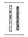
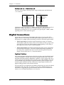
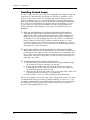
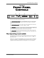
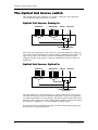
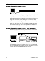
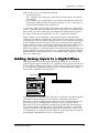
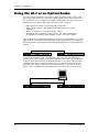
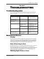
ALESIS
AI-3
Reference Manual
Introduction
Introduction
Thank you for purchasing the Alesis AI-3 20-bit Analog-Optical Interface. To take
full advantage of the AI-3’s functions, and to enjoy long and trouble free use, please
read this user’s manual carefully.
How To Use This Manual
This manual is divided into the following sections describing the various features of
the AI-3. Though we recommend you take time to read through the entire manual
once carefully, those having general knowledge about digital converters should use
the table of contents and index to reference specific functions while using this device.
Chapter 1: Connections. Deals with the necessary analog and digital connections
necessary before using the AI-3.
Chapter 2: Front Panel Controls. Explains the function of each light and button on
the AI-3’s front panel.
Chapter 3: Applications. Connecting the AI-3 to other equipment in your studio.
Chapter 4: Troubleshooting. Problems and solutions, service information, and
specifications.
When something important appears in the manual, an icon (like the one on the left) will appear in the left
margin. This symbol indicates that this information is vital when operating the AI-3.
✪
AI-3 Reference Manual
1
Introduction
IMPORTANT SAFETY
INSTRUCTIONS
Safety symbols used in this product
This symbol alerts the user that there are important operating and maintenance
instructions in the literature accompanying this unit.
This symbol warns the user of uninsulated voltage within the unit that can cause
dangerous electric shocks.
Please follow these precautions when
using this product:
1. Read these instructions.
2. Keep these instructions.
3. Heed all warnings.
4. Follow all instructions.
5. Do not use this apparatus near water.
6. Clean only with a damp cloth. Do not spray any liquid cleaner onto the
faceplate, as this may damage the front panel controls or cause a
dangerous condition.
7. Install in accordance with the manufacturer's instructions.
8. Do not install near any heat sources such as radiators, heat registers,
stoves, or other apparatus (including amplifiers) that produce heat.
9. Do not defeat the safety purpose of the polarized or grounding-type plug.
A polarized plug has two blades with one wider than the other. A
grounding-type plug has two blades and a third grounding prong. The
wide blade or the third prong are provided for your safety. When the
provided plug does not fit into your outlet, consult an electrician for
replacement of the obsolete outlet.
AI-3 Reference Manual
3
10. Protect the power cord from being walked on or pinched, particularly at
plugs, convenience receptacles, and the point where they exit from the
apparatus.
11. Use only attachments or accessories specified by the manufacturer.
12.Use only with a cart, stand, bracket, or table designed for use with
professional audio or music equipment. In any installation, make sure
that injury or damage will not result from cables pulling on the apparatus
and its mounting. If a cart is used, use caution when moving the cart/
apparatus combination to avoid injury from tip-over.
13. Unplug this apparatus during lightning storms or when unused for long
periods of time.
14. Refer all servicing to qualified service personnel. Servicing is required
when the apparatus has been damaged in any way, such as when the
power-supply cord or plug is damaged, liquid has been spilled or objects
have fallen into the apparatus, the apparatus has been exposed to rain or
moisture, does not operate normally, or has been dropped.
15. This unit produces heat when operated normally. Operate in a wellventilated area.
16. This product, in combination with an amplifier and headphones or
speakers, may be capable of producing sound levels that could cause
permanent hearing loss. Do not operate for a long period of time at a high
volume level or at a level that is uncomfortable. If you experience any
hearing loss or ringing in the ears, you should consult an audiologist.
4
AI-3 Reference Manual
Introduction
Instructions de Sécurité Importantes
(French)
Symboles utilisés dans ce produit
Ce symbole alèrte l’utilisateur qu’il existe des instructions de fonctionnement et de
maintenance dans la documentation jointe avec ce produit.
Ce symbole avertit l’utilisateur de la présence d’une tension non isolée à l’intérieur de
l’appareil pouvant engendrer des chocs électriques.
Veuillez suivre ces précautions lors de
l’utilisation de l’appareil:
1.
Lisez ces instructions.
2.
Gardez ces instructions.
3.
Tenez compte de tous les avertissements.
4.
Suivez toutes les instructions.
5.
N’utilisez pas cet allareil à proximité de l’eau.
6.
Ne nettoyez qu’avec un chiffon humide. Ne pas vaporiser de liquide nettoyant
sur l’appareil, cela pourrait abîmer les contrôles de la face avant ou engendrer
des conditions dangeureuses.
7.
Installez selon les recommandations du constructeur.
8.
Ne pas installer à proximilé de sources de chaleur comme radiateurs, cuisinière
ou autre appareils (don’t les amplificateurs) produisant de la chaleur.
9.
Ne pas enlever la prise de terre du cordon secteur. Une prise murale avec terre
deux broches et une troisièrme reliée à la terre. Cette dernière est présente pour
votre sécurité. Si le cordon secteur ne rentre pas dans la prise de courant,
demandez à un électricien qualifié de remplacer la prise.
10. Evitez de marcher sur le cordon secteur ou de le pincer, en particulier au niveau
de la prise, et aux endroits où il sor de l’appareil.
11. N’utilisez que des accessoires spécifiés par le constructeur.
12. N’utilisez qu’avec un stand, ou table conçus pour l’utilisation d’audio
professionnel ou instruments de musique. Dans toute installation, veillez de ne
rien endommager à cause de câbles qui tirent sur des appareils et leur support.
13. Débranchez l’appareil lors d’un orage ou lorsqu’il n’est pas utilisé pendant
longtemps.
AI-3 Reference Manual
5
14. Faites réparer par un personnel qualifié. Une réparation est nécessaire lorsque
l’appareil a été endommagé de quelque sorte que ce soit, par exemple losrque le
cordon secteur ou la prise sont endommagés, si du liquide a coulé ou des objets
se sont introduits dans l’appareil, si celui-ci a été exposé à la pluie ou à
l’humidité, ne fonctionne pas normalement ou est tombé.
15. Cet appareil produit de la chaleur en fonctionnement normal.
16. Ce produit, utilisé avec un amplificateur et un casque ou des enceintes, est
capable de produite des niveaux sonores pouvant engendrer une perte
permanente de l’ouïe. Ne l’utilisez pas pendant longtemps à un niveau sonore
élevé ou à un niveau non confortable. Si vous remarquez une perte de l’ouïe ou
un bourdonnement dans les oreilles, consultez un spécialiste.
6
AI-3 Reference Manual
Introduction
Beim Benutzen dieses Produktes beachten
Sie bitte die folgenden
Sicherheitshinweise: (German)
1.
Lesen Sie die Hinweise.
2.
Halten Sie sich an die Anleitung.
3.
Beachten Sie alle Warnungen.
4.
Beachten Sie alle Hinweise.
5.
Bringen Sie das Gerät nie mit Wasser in Berührung.
6.
Verwenden Sie zur Reinigung nur ein weiches Tuch. Sprühen Sie keine flüssiger
Reiniger auf die Oberfläche, dies könnte zur Beschädigung der Vorderseite
führen und auch weitere Schäden verursachen.
7.
Halten Sie sich beim Aufbau des Gerätes an die Angaben des Herstellers.
8.
Stellen Sie das Gerät nich in der Nähe von Heizkörpern, Heizungsklappen oder
anderen Wärmequellen (einschließlich Verstärkern) auf.
9.
Verlegen Sie das Netzkabel des Gerätes niemals so, daß man darüber stolpern
kann oder daß es gequetscht wird.
10. Benutzen Sie nur das vom Hersteller empfohlene Zubehör.
11. Verwenden Sie ausschließlich Wagen, Ständer, oder Tische, die speziell für
professionelle Audio- und Musikinstrumente geeignet sind. Achten Sie immer
darauf, daß die jeweiligen Geräte sicher installiert sind, um Schäden und
Verletzungen zu vermeiden. Wenn Sie einen Rollwagen benutzen, achten Sie
darauf, das dieser nicht umkippt, um Verletzungen auszuschließen.
12. Ziehen Sie während eines Gewitters oder wenn Sie das Gerät über einen
längeren Zeitraum nicht benutzen den Netzstecher aus der Steckdose.
13. Die Wartung sollte nur durch qualifiziertes Fachpersonal erfolgen. Die Wartung
wird notwendig, wenn das Gerät beschädigt wurde oder aber das Stromkabel
oder der Stecker, Gegenstände oder Flüssigkeit in das Gerät gelangt sind, das
Gerät dem Regen oder Feuchtigkeit ausgesetzt war und deshalb nicht mehr
normal arbeitet oder heruntergefallen ist.
14. Bei normalem Betrieb des Gerätes kommt es zu Wärmeentwicklungen.
15. Dieses Produkt kann in Verbindung mit einem Verstärker und Kopfhörern oder
Lautsprechern Lautstärkepegel erzeugen, die anhaltende Gehörschäden
verursachen. Betreiben Sie es nicht über längere Zeit mit hoher Lautstärke oder
einem Pegel, der Ihnen unangenehm is. Wenn Sie ein Nachlassen des Gehörs
oder ein Klingeln in den Ohren feststellen, sollten Sie einen Ohrenarzt aufsuchen.
AI-3 Reference Manual
7
CE Declaration of Conformity
Manufacturer’s Name:
Manufacturer’s Address:
Alesis Corporation
1633 26th Street
Santa Monica, CA 90404
US
declares, that the product:
Product Name:
Model Type:
AI-3
Analog-Optical Converter
conforms to the following Standards:
EMC:
EN 55103:1997 Class B
(All tests were performed with fully-shielded
cabling)
Safety:
EN 60065
European Contact:
Sound Technology plc
17 Letchworth Point, Letchworth,
Hertfordshire, SG6 1 ND, England
Phone: +44.1462.480000
Fax: +44.1462.480800
June, 1999
8
AI-3 Reference Manual
Contents
CONTENTS
1: Connections......................................................................... 11
Unpacking and Inspection ............................................................................................................ 11
Analog Connections ....................................................................................................................... 11
Inputs ................................................................................................................................. 11
Outputs .............................................................................................................................. 11
Balanced vs. Unbalanced................................................................................................ 12
Digital Connections ........................................................................................................................ 12
Optical Cables................................................................................................................... 12
Powering Up.................................................................................................................................... 13
AC Power Hookup ......................................................................................................................... 13
Line Conditioners and Protectors ................................................................................. 13
Avoiding Ground Loops ................................................................................................ 14
2: Front Panel Controls ........................................................... 15
Front Panel Controls....................................................................................................................... 15
The Operating Level switch.......................................................................................................... 15
The Optical Out Source switch..................................................................................................... 16
Optical Out Source: Analog In ...................................................................................... 16
Optical Out Source: Optical In ...................................................................................... 16
3: Applications........................................................................ 17
Digital Clock .................................................................................................................................... 17
Recording with ADAT/EDIT....................................................................................................... 18
Recording with ADAT/EDIT and an ADAT ............................................................................ 18
Adding Analog Inputs to a Digital Mixer .................................................................................. 19
Using the AI-3 as a Digital Snake ................................................................................................ 20
4: Troubleshooting ................................................................. 21
Troubleshooting Index................................................................................................................... 21
Maintenance/Service ..................................................................................................................... 21
Cleaning............................................................................................................................. 21
Refer All Servicing to Alesis .......................................................................................... 21
Obtaining Repair Service at Alesis ............................................................................... 22
Obtaining Repair Service at an Alesis Service Center............................................... 22
Specifications ......................................................................... 23
AI-3 Reference Manual
9
10
Power
REAR PANEL
FRONT PANEL
ADAT Optical Out
Signal LED
Analog Inputs
ADAT Optical In
Optical Out
Source Switch
Operating Level
Switch
Clip LED
Analog Outputs
Power
Switch
Contents
AI-3 Reference Manual
Connections – Chapter 1
CHAPTER 1
CONNECTIONS
Unpacking and Inspection
Your AI-3 was carefully packed at the factory, and the shipping carton was designed
to protect the unit during shipping. Please retain this container in the unlikely event
that you need to return the AI-3 for servicing.
The shipping carton should contain the following items:
•
•
•
•
✪
This instruction manual
Alesis AI-3 with the same serial number as shown on shipping carton
AC Power cable
Alesis warranty card
It is important to register your purchase; if you have not already filled out your warranty
card and mailed it back to Alesis, please take the time to do so now.
Analog Connections
The AI-3 has eight analog inputs and outputs. These are designed for line level (not
mic level) signals, such as those from a mixing console or recorder.
•
Inputs. There are eight balanced or unbalanced 1/4” analog inputs. These send
audio to the corresponding channel of the ADAT Optical Digital Output. (This is
true only if the front panel “Optical Out Source” switch is set to “Analog In”, see
Chapter 2, “Front Panel Controls” for details.)
•
Outputs. There are eight balanced or unbalanced 1/4” analog outputs. These
convert the ADAT Optical Digital Input signal to an analog signal suitable for
use with analog mixers and monitors. Unlike the Analog Inputs, the Analog
Outputs are always active.
AI-3 Reference Manual
11
Chapter 1 – Connections
Balanced vs. Unbalanced
The AI-3’s analog Inputs and Output jacks accept both Balanced and Unbalanced
1/4” connectors.
Unbalanced Line Input
Balanced Line Input
Signal
Tip
Hot
Tip
Cold
Ground
Tip
Sleeve
A
A
A
Ground
Tip
Sleeve
Ring
Ring
Sleeve
AA
AA
A
AA
Sleeve
Unbalanced signals are usually at a –10dBV operating level, and balanced signals are
typically at a +4dBu operating level. See the next chapter for instructions on
changing the operating level, or you can recklessly try pressing the “-10dBV/+4dBu
Operating Level” switch on the front panel.
Digital Connections
The AI-3 has an ADAT Optical Digital Input and Output on its rear panel. These
digital connectors cannot accept a S/PDIF Optical Digital signal (from a DAT, CD or
DVD player, for example) without first being converted to the ADAT Optical format.
•
ADAT Optical Input. The ADAT Optical Digital Input accepts an 8-channel
ADAT Optical signal and sends it to the D/A converters for analog output. (This
signal can also be fed to the ADAT Optical Output depending on the setting of
the “Optical Out Source” button on the front panel.)
•
ADAT Optical Output. The ADAT Optical Digital Output outputs signal either
from the eight analog inputs or the ADAT Optical Digital Input, depending on
the setting of the “Optical Out Source” button on the front panel. See the next
chapter, “Front Panel Controls”, for more information.
Optical Cables
The optical transmitter and receiver used in Alesis products using the ADAT Optical
format are designed to transmit and receive through plastic fiber cables (APF). The
maximum APF cable length recommended is 10 meters (33 feet). Optical cables up to
5 meters in length can be purchased through Alesis Parts (800 5-ALESIS). Alesis does
not recommend using cable lengths longer than 10 meters because the light output
from the optical transmitter becomes attenuated at longer lengths and may cause
digital clocking problems at the destination device.
If longer cable runs are required, the transmitter and receiver parts can be desoldered
and replaced. This will void your warranty. Contact Alesis Technical Support for
information on upgrading the optical transmitter and receiver at an Alesis Service
Center, or look for further information on our web site.
12
AI-3 Reference Manual
Connections – Chapter 1
Powering Up
After making your connections, turn on the system’s power using this procedure:
✿ Before turning on the AI-3’s power, check the following items:
•
•
✿
Have all connections been made correctly?
Are the volume controls of the amplifier or mixer turned down?
Insert the end of the IEC power cable into the [POWER] input on the rear panel
of the AI-3 and plug the other end into a wall jack. Flip the Power switch to the
up position.
Upon power-up, the display will briefly illuminate all front panel LEDs.
✿ Turn on the power of the amplifier/mixer, and adjust the volume.
AC Power Hookup
The AI-3 has a universal a power input suitable for voltage from 100 to 240V, 50 or 60
Hz. The unit comes with an IEC cable suitable for the country it was sold in.
With the AI-3 switched off, plug the end of the IEC power adapter cord into AI-3’s
[POWER] socket and the male (plug) end into a source of AC power. It’s good
practice to not plug in the AI-3 until all other cables are hooked up.
✪
Alesis cannot be responsible for problems caused by using the AI-3 or any associated
equipment with improper AC wiring.
Line Conditioners and Protectors
Although the AI-3 is designed to tolerate typical voltage variations, in today’s world
the voltage coming from the AC line may contain spikes or transients that can
possibly stress your gear and, over time, cause a failure. There are three main ways
to protect against this, listed in ascending order of cost and complexity:
•
Line spike/surge protectors. Relatively inexpensive, these are designed to
protect against strong surges and spikes, acting somewhat like fuses in that they
need to be reset or replaced if they’ve been hit by an extremely strong spike.
•
Line filters. These generally combine spike/surge protection with filters that
remove some line noise (dimmer hash, transients from other appliances, etc.).
•
Uninterruptible power supply (UPS). This is the most sophisticated option. A
UPS provides power even if the AC power line fails completely. Intended for
computer applications, a UPS allows you to complete an orderly shutdown of a
computer system in the event of a power outage, and the isolation it provides
from the power line minimizes all forms of interference—spikes, noise, etc.
AI-3 Reference Manual
13
Chapter 1 – Connections
Avoiding Ground Loops
In today’s studio, where it seems every piece of equipment has complex routing and
computer logic, there are many opportunities for ground loop problems to occur.
These show up as hums, buzzes or sometimes radio reception and can occur if a
piece of equipment “sees” two or more different paths to ground. While there are
methods to virtually eliminate ground loops and stray radio frequency interference,
most of the professional methods are expensive and involve installing a separate
power source just for the sound system. Here are some easy helpful hints that a
professional studio installer might use to keep those stray hums and buzzes to a
minimum.
➀ KEEP ALL ELECTRONICS OF THE SOUND SYSTEM ON THE SAME AC
ELECTRICAL CIRCUIT. Most stray hums and buzzes happen as a result of
different parts of the sound system being plugged into outlets of different AC
circuits. If any noise generating devices such as air conditioners, refrigerators,
neon lights, etc., are already plugged into one of these circuits, you then have a
perfect condition for stray buzzes. Since most electronic devices of a sound
system don’t require a lot of current (except for power amplifiers), it’s usually
safe to run a multi-outlet box or two from a SINGLE wall outlet and plug in all of
the components of your system there.
➁ KEEP AUDIO WIRING AS FAR AWAY FROM AC WIRING AS POSSIBLE.
Many hums come from audio cabling being too near AC wiring. If a hum occurs,
try moving the audio wiring around to see if the hum ceases or diminishes. If it’s
not possible to separate the audio and AC wiring in some instances, make sure
that the audio wires don’t run parallel to any AC wire (they should only cross at
right angles, if possible).
➂ TO ELIMINATE HUM IF THE ABOVE HAS FAILED:
A) Disconnect the power from all outboard devices and tape machines except
for the mixer and control room monitor power amp.
B) Plug in each tape machine and outboard effects device one at a time. If
possible, flip the polarity of the plug of each device (turn it around in the
socket) until the quietest position is found.
C) Make sure that all of the audio cables are in good working order. Cables with
a detached ground wire will cause a very loud hum!!
D) Keep all cables as short as possible, especially in unbalanced circuits.
If the basic experiments don’t uncover the source of the problem, consult your dealer
or technician trained in proper studio grounding techniques. In some cases, a “star
grounding” scheme must be used, with the mixer at the center of the star providing
the shield ground on telescoping shields, which do NOT connect to the chassis
ground of other equipment in the system.
14
AI-3 Reference Manual
Front Panel Controls – Chapter 2
CHAPTER 2
FRONT PANEL
CONTROLS
➀
➁
➂
➃
The AI-3’s Front Panel contains the following:
① Optical Out Source switch. This switch determines which source signal will be
sent to the ADAT Optical Digital output, either the Analog inputs or the Optical
input.
➁ Operating Signal switch. This switch controls the operating level of the analog
inputs and outputs. It can be set for either –10dBV or +4dBu.
➂ Input Meters. These meters show the level of the signal going into the AI-3. The
green SIGNAL LED indicates –20 dBfs and the red CLIP LED indicates -2 dBfs. Any
audio recorded while the Input meters read CLIP may be distorted.
➃ Power switch. The Power switch turns the unit on. This is the most important
control on the front panel of the AI-3 – the wrong setting of this switch negates any
other advice given in this manual.
The Operating Level switch
The Operating Level switch controls the signal level from and to the analog inputs
and outputs. It can be set for either –10dBV (-15 dBfs = 0.178 Volts) or +4dBu (-15
dBfs = 0.138 Volts).
In most cases, -10 signals are unbalanced (see page 12) and +4 signals are balanced,
but there are exceptions. To determine the proper operating level for your studio
equipment, check the Reference Manual of the product(s) you are connecting to.
AI-3 Reference Manual
15
Chapter 2 – Front Panel Controls
The Optical Out Source switch
The “Optical Out Source” switch has two settings, “Analog In” and “Optical In”,
with an LED indicating which mode is selected.
Optical Out Source: Analog In
ANALOG IN
ANALOG OUT
ADAT IN
ADAT OUT
OPTICAL OUT SOURCE:
ANALOG IN
Analog In is the typical mode for the AI-3 to be used in. The eight analog inputs are
sent to the ADAT Optical Digital Out, and the ADAT Optical Digital In is sent to the
eight analog outputs. This mode is useful for recording with the ADAT/EDIT
computer system, routing signals to and from a digital mixer, and most other AI-3
applications.
Optical Out Source: Optical In
ANALOG IN
ANALOG OUT
ADAT IN
ADAT OUT
OPTICAL OUT SOURCE:
OPTICAL IN
The Optical In mode is a feature included to avoid repatching when using the AI-3
with other ADAT Optical devices. When the Optical Out source is set to Optical In,
any ADAT Optical Input is routed directly to the ADAT Optical Output. This can be
useful in systems using an AI-3 with a ADAT/EDIT computer system and an ADAT.
See Chapter 3, “Applications”, for some examples using this mode.
Note that the ADAT Optical Input is routed to both the ADAT Optical Output and
the eight Analog outputs in this mode.
16
AI-3 Reference Manual
Applications – Chapter 3
CHAPTER 3
APPLICATIONS
Where the previous chapters explained the various connectors and switches on the
AI-3, this chapter describes how to connect it to the components in your studio. Since
the AI-3 doesn’t do much on it’s own, this chapter will help you get the most out of
this interface.
Digital Clock
The most important concept to understand in a studio using several digital
connectors is the digital clock. It’s critical that every unit being connected with a
digital connector like an ADAT Optical cable is running at the same clock speed.
Digital audio signals like the ADAT Optical format are made up of digital sample
words. Each word is a burst of numbers: a 20-bit, 48kHz signal is made up of a word
20 bits long, played 48,000 times every second. If the sending unit and the receiving
unit aren’t in perfect sync then the signal will be distorted. For example, if an ADAT
was running at 48,000 samples per second (48kHz), and your digital mixer was
running at 48,001 samples per second, you would hear a “click” when the samples
didn’t exactly line up.
The way to fix this is to set every unit in your studio to run from the same master
clock. Whether it’s an ADAT, computer-based editing workstation, digital mixer or
DAT machine, you need to pick one unit in your studio which is the master clock,
and every other digitally-connected unit needs to slave to this master.
How does this affect the AI-3? The easiest way to use an AI-3 in a digital studio is to
make sure that the digital input is always connected. When digital clock is coming
into the AI-3’s digital input, it automatically slaves to this clock source. If you only
connect the digital output of the AI-3 to another product, such as a mixer or recorder,
then the AI-3 has to be the master clock.
The next few pages illustrate a few example setups using the AI-3. Use these
configurations as a guide when setting up the AI-3 in your studio.
AI-3 Reference Manual
17
Chapter 3 – Applications
Recording with ADAT/EDIT
The Alesis ADAT/EDIT is a recording system, sold separately, which uses the ADAT
Optical Digital Interface for digital audio input and output. When connected to an
AI-3, this system forms a complete 8 in/8 out hard disk recording workstation.
In the configuration pictured above, the ADAT Output of the AI-3 is connected to the
ADAT Input of the PCR (the PCI card packaged with ADAT/EDIT). The ADAT
Output of the PCR is connected to the ADAT Input of the AI-3. The Analog Outputs
of the AI-3 are connected to the Tape Returns of the analog mixer, and the Analog
Inputs are connected to the Group Outputs of the mixer.
In this setup, when you press Play on the ADAT/EDIT software, the audio will play
through the AI-3 into the mixer. When you plug a microphone into the mixer, you
can route it to the Group Outputs to send it through the AI-3 into the PCR card to be
recorded in ADAT/EDIT.
Recording with ADAT/EDIT and an ADAT
Since the AI-3 has an Optical Source switch, you can connect both an ADAT and an
AI-3 to the ADAT/EDIT system.
In the system pictured above, the ADAT Output of the PCR card is plugged into the
AI-3 ADAT In, the Out of the AI-3 is connected to the In of our ADAT Recorder, and
the Out of our ADAT Recorder is connected to the Input of the PCR card. If you want
to listen to what you’ve recorded, monitor the outputs of the AI-3.
18
AI-3 Reference Manual
Applications – Chapter 3
There are three ways to record into the PCR card:
•
•
•
Play the ADAT tape
Press “All Input” and “Analog In” on the ADAT and send signal to the ADAT’s
analog inputs
Press “All Input” and “Optical Input” on the ADAT and send audio to the AI-3’s
analog inputs. (Make sure that the “Optical Out Source” is set to “Analog In” on
the AI-3 when recording in this configuration.)
To record the output of ADAT/EDIT on the ADAT tape, set the AI-3’s “Optical Out
Source” to Optical In, press the “Digital In” button on the ADAT, and arm the ADAT
tracks where you want to record. Also, the computer should be the master clock in
this setup, so make sure that the ADAT is not set to “Clock Source: Internal”.
There is another way to connect this system. First, the output of the PCR card is
connected to the ADAT’s Digital In. Next, the Digital Out of the ADAT is connected
to the Digital In of the AI-3, and the Digital Out of the AI-3 is connected to the Digital
In of the computer’s PCR card. In this system, you can record into the computer by
playing audio into the AI-3’s analog inputs, and monitor through the ADAT’s analog
outputs. However, you must press Digital Input and All Input on the ADAT to
monitor the computer. To record the output of the ADAT to the computer, make sure
that the Optical Source switch on the AI-3 is set to Optical In. This setup is not much
different than the system pictured above, you can decide which configuration better
suits your working style.
Adding Analog Inputs to a Digital Mixer
Many digital mixers feature the ADAT Optical digital input; it’s one of the most
popular digital formats available due to its compact size and versatility. The AI-3 can
be very useful for adding analog inputs to a mixer with extra ADAT I/O. This allows
you to connect more synthesizers, effects processors, analog multitrack recorders, or
other products which don’t have digital I/O.
ADAT INPUT
1
2
3
4
5
6
7
ADAT OUTPUT
8
9
10
11
12
13
14 15
16
17
18
In the diagram above, the Digital Out of the AI-3 is connected to the ADAT Digital In
of the mixer. The ADAT Digital Out of the mixer is connected to the AI-3. It’s
important to connect both the input and output of the AI-3 to the digital mixer, even
if you aren’t going to be sending audio to the AI-3’s analog outputs. If only the
Digital Out of the AI-3 is connected to the mixer, the AI-3 becomes the clock master
for your entire studio, which may create clock problems. If you must use the ADAT
output of your mixer for another purpose, make sure that the mixer’s “clock source”
or “clock master” is set to the AI-3’s ADAT input. You should also make sure that all
other digitally-connected devices are set to external clock.
AI-3 Reference Manual
19
Chapter 3 – Applications
Using the AI-3 as an Optical Snake
Two AI-3s can be connected to each other to create an optical “snake”. This system
allows eight analog lines to be converted to 20-bit digital signals and routed up to 33
feet (10 meters) away to another AI-3 or ADAT optical device. (See page 12 for more
information about optical cables.) The advantages to this system are:
•
•
•
•
Eight signals are carried on one thin-profile optical cable
Signals are not subject to interference from transformer noise or radio
frequencies
There is no signal loss as the signal run gets longer
The signals can be converted to analog close to the source (a microphone
preamplifier, for example), then digitally routed to a recorder or mixer
This system can be used in fixed installations, in ADAT recording studios, live sound
reinforcement or anywhere high-quality digital audio signals need to be transferred.
When wiring this system, make sure that the fragile optical cables are protected from
damage.
Note that this communication is one-directional only. One AI-3 will send signal to
another, but if you try sending optical data from the second back to the first, there is
no master clock. Since the AI-3 automatically defaults to slave clock if digital audio is
coming into the unit, both devices will try to slave to each other and no audio will
play back. If you need to send audio back and forth from two units, insert another
device (such as a Q20, ADAT or PCR card) in the loop and set this to Master clock.
20
AI-3 Reference Manual
Troubleshooting – Chapter 4
CHAPTER 4
TROUBLESHOOTING
Troubleshooting Index
If you are experience problems while operating the AI-3, please use the following
table to locate possible causes and solutions before contacting Alesis customer
service for assistance.
Symptom
Cause
Solution
The display does not light
when the unit is powered
on.
Sound is distorted, Red
“Clip” LEDs are lit
No signal going to the
ADAT output
No power.
Check that the power cable
is plugged in properly.
Input level is too high.
Low signal level
“Operating Level”
switch in the wrong
position
Mixing balanced and
unbalanced cables
Hum or noise from output.
Ground loop.
Unit does not respond to
front panel controls.
Unknown software
conflict, Chupacabra, or
static electricity.
Turn down the input
source.
Check the setting of the
“Optical Source” switch on
the front panel
Check the setting of the
“Operating Level” switch
on the front panel
Choose balanced or
unbalanced cables
throughout your studio
Try plugging the unit into
another power jack or
different audio cables.
Power down and power up
again.
“Optical Source” switch
in the wrong position
Maintenance/Service
Cleaning
Disconnect the AC cord, then use a damp cloth to clean the AI-3’s metal and plastic
surfaces. For heavy dirt, use a non-abrasive household cleaner such as Formula 409
or Fantastik. DO NOT SPRAY THE CLEANER DIRECTLY ONTO THE FRONT OF
THE UNIT AS IT MAY DESTROY THE LUBRICANTS USED IN THE SWITCHES
AND CONTROLS! Spray onto a cloth, then use cloth to clean the unit.
Refer All Servicing to Alesis
We believe that the AI-3 is one of the most reliable multieffects processors that can be
made using current technology, and should provide years of trouble-free use.
However, should problems occur, DO NOT attempt to service the unit yourself. High
voltage/high current DC voltages are present at several points within the chassis.
Service on this product should be performed only by qualified technicians. NO
USER-SERVICEABLE PARTS INSIDE.
Obtaining Repair Service at Alesis
AI-3 Reference Manual
21
Chapter 4 – Troubleshooting
Before contacting Alesis, check over all your connections, and make sure you’ve read
the manual.
Customers in the USA and Canada: If the problem persists, call Alesis USA at
1-800-5-ALESIS and request the Product Support department. Talk the problem over
with one of our technicians; if necessary, you will be given a return order (RO)
number and instructions on how to return the unit. All units must be shipped
prepaid and COD shipments will not be accepted.
For prompt service, indicate the RO number on the shipping label. If you do not have
the original packing, ship the AI-3 in a sturdy carton, with shock-absorbing materials
such as styrofoam pellets (the kind without CFCs) or “bubble-pack” surrounding the
unit. Shipping damage caused by inadequate packing is not covered by the Alesis
warranty.
Tape a note to the top of the unit describing the problem, include your name and a
phone number where Alesis can contact you if necessary, as well as instructions on
where you want the product returned. Alesis will pay for standard one-way shipping
back to you on any repair covered under the terms of this warranty. Next day service
is available for a surcharge.
Field repairs are not normally authorized during the warranty period, and repair
attempts by unqualified personnel may invalidate the warranty.
Service address for customers in the USA:
Alesis Product Support
Attention: RO #XXXXXX
12520 Wilkie Ave.
Hawthorne, CA 90250
Customers outside the USA and Canada:
Contact your local Alesis distributor for any warranty assistance. The Alesis Limited
Warranty applies only to products sold to users in the USA and Canada. Customers
outside of the USA and Canada are not covered by this Limited Warranty and may
or may not be covered by an independent distributor warranty in the country of sale.
Do not return products to the factory unless you have been given specific
instructions to do so.
Obtaining Repair Service at an Alesis Service
Center
If your unit needs servicing and is under warranty, and you wish to bring it to a local
Alesis Service Center, you do not need an RO number. Just bring the unit and a copy
of your sales receipt to the service center – Alesis will take care of the rest. Unless you
are sending the unit to Alesis for repair, you do not need an RO number.
22
AI-3 Reference Manual
Specifications
SPECIFICATIONS
Analog Input
Number of Channels:
Format:
Nominal Level:
Maximum Level:
Impedence:
8
1/4" balanced
-10 dBV or +4dBu, front- panel adjustable
+10 dBV
1MΩ/channel stereo, 500kΩ/channel mono
Analog Input to Optical Output
A/D converter:
Frequency Response:
Signal to Noise (A-wtg.):
Dynamic Range (-60dBfs, 1kHz):
THD+Noise (-0.5dBfs, 1kHz):
20 bit Sigma-Delta, 128 times oversampling
20Hz to 20 kHz, (+0.05dB/-0.10dB balanced,
+0.05/-0.15 unbalanced)
100dB balanced/unbalanced
96dB balanced/unbalanced
0.0025% balanced, 0.0023% unbalanced
Analog Output
Number of Channels:
Format:
Maximum Level:
Nominal Level
Output Impedance:
8
1/4" balanced
+17.5dBu
-10 dBV or +4dBu, front- panel adjustable
500 ohms
Analog Input to Optical Output
D/A converter:
Frequency Response:
Signal to Noise (A-wtg.):
Dynamic Range (-60dBfs, 1kHz):
THD+Noise (-0.5dBfs, 1kHz):
20 bit Sigma-Delta, 128 times oversampling
20Hz to 20 kHz, (±0.1dB balanced/unbalanced)
98dB balanced/unbalanced
95dB balanced/unbalanced
0.0030% balanced/unbalanced
Front Panel
Buttons
Indicators
AI-3 Reference Manual
OPTICAL SOURCE
OPERATING LEVEL
LED Signal/Peak indicators
Power Indicator
23
Specifications
Rear Panel
Analog Inputs (8)
Analog Outputs (8)
Digital Input
Digital Output
Power
1/4" 3-conductor
1/4" 3-conductor
EIAJ fiber optical jack, ADAT Optical digital
format
EIAJ fiber optical jack, ADAT Optical digital
format
IEC jack
General
Power Requirements:
Power Consumption:
Dimensions (W x H x D):
Weight:
24
90V-250V AC, 50/60Hz
80W
19” x 1.75” x 6” (483mm x 45mm x 153mm)
4.5lbs. (2kg.)
AI-3 Reference Manual