1
Reference Manual
This page intentionally left blank
10%
20%
30%
40%
50%
60%
Copyright 2002, Alesis. All rights reserved
Reproduction in whole or in part is prohibited.
Specifications subject to change without notice.
All trademarks are the property of their respective holders.
7-51-0114-A
8/2002
70%
80%
90%
100%
Table of Contents
Introduction....................................................................3
Welcome! .........................................................................................................3
About the Phlngr............................................................................4
Important features of your Phlngr..............................................................4
Phlngr Key Features ......................................................................................5
How to Use This Manual.............................................................6
Safety Instructions/Notices .....................................7
Important Safety Instructions (English)............................7
Safety symbols used in this product............................................................7
Please follow these precautions when using this product: .....................7
CE Declaration Of Conformity................................................9
FCC Compliance Statement......................................................9
Instructions de Sécurité Importantes (French) .........................................10
Lesen Sie bitte die folgende Sicherheitshinweise
(German) ..................................................................................................12
Quick Start Guide ........................................................15
If you can’t wait to get started......................................................................15
Hook it up to a synthesizer...........................................................................15
A quick overview of the controls ...........................................16
Rear Panel ........................................................................................................16
Connections ....................................................................17
Unpacking and Inspection............................................................................17
Installing in a Rack .........................................................................................17
Power................................................................................................................17
Connecting to the Channel Inserts of a mixing console: ........................19
Connecting to the Main Outputs of a mixing console: ...........................20
Connecting to the Effect Send/Return of a mixing
console: .....................................................................................................21
Connecting to the inserts on an instrument amplifier: ............................22
Connecting to equipment with XLR inputs and outputs:.......................23
About audio cables.........................................................................................23
Using the ModLink........................................................................24
Using the Phlngr...........................................................25
About flanging.................................................................................25
Stereo source ...................................................................................................26
Mono source ...................................................................................................26
What is Tempo Sync? ....................................................................................27
To turn Tempo Sync off:..............................................................................27
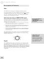
Description of Controls...............................................................28
Rate ...................................................................................................................28
Depth................................................................................................................28
Center ...............................................................................................................29
Regen................................................................................................................29
TYPE Rocker Switch.....................................................................................32
1
Table Of Contents
Reset Mod........................................................................................................34
Tap Tempo......................................................................................................35
Bypass...............................................................................................................36
Using the Foot Switch ...................................................................................36
Sample Settings.............................................................37
Blank Settings Templates ..............................................................................40
Troubleshooting............................................................41
Troubleshooting Index................................................................41
Avoiding ground loop noise.........................................................................43
Line conditioners and spike protectors ......................................................44
Care and Maintenance ................................................................45
Cleaning............................................................................................................45
Refer all servicing to Alesis...........................................................................45
Obtaining repair service ................................................................................46
Specifications.................................................................47
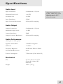
Audio Input .....................................................................................................47
Audio Output..................................................................................................47
Audio Performance........................................................................................47
Mechanical .......................................................................................................47
Index...................................................................................49
Warranty/Contact Alesis ...........................................50
Alesis Limited Warranty................................................................................50
Alesis Contact Information ..........................................................................51
2
Introduction
Welcome!
Thank you for making the Alesis Phlngr a part of your studio.
Since 1984, we've been designing and building creative tools for
the audio community. We believe in our products, because we've
heard the results that creative people like you have achieved with
them. One of Alesis' goals is to make high-quality studio
equipment available to everyone, and this Reference Manual is an
important part of that. After all, there's no point in making
equipment with all kinds of capabilities if no one explains how to
use them. So, we try to write our manuals as carefully as we build
our products.
For more effective
service and product
update notices, please
register your Phlngr
online at:
http://www.alesis.com/
support/warranty.htm
The goal of this manual is to get you the information you need as
quickly as possible, with a minimum of hassle. We hope we've
achieved that. If not, please drop us an email and give us your
suggestions on how we could improve future editions of this
manual.
We hope your investment will bring you many years of creative
enjoyment and help you achieve your goals.
Sincerely,
The people of Alesis
3
Introduction
About the Phlngr
Your new Phlngr is a member of the Alesis ModFX family of
performance effects boxes. This particular ModFX unit is a stereo
flanger effect with modulation controls.
Each box in the line provides a different set of sound effects and
signal processing, and they are easy to arrange and connect to each
other. With a uniform, friendly, uncomplicated user interface and
high-resolution digital processing, the ModFX product line is
perfect for keyboardists, guitarists, and any other studio or live
performance artists.
Important features of your Phlngr
High Resolution Processing
The Phlngr internally uses 28-bit stereo digital signal processing.
The digital-to-analog and analog-to-digital conversion is sampled
at 48kHz with 24 bits of resolution. That means you can get the
effect you want, without adding unwanted noise and distortion.
ModLink
If you’re using multiple ModFX boxes to make your own unique
effects chain, ModLink makes it easy to hookup without needing
patch cords between units in a chain. The nine-pin connectors
built into each side of the case enable a ModFX box to transfer
digital audio and word clock directly to another. Any number of
units can be connected together.
Configurable Modulation
The Phlngr lets you select from five different types of stereo and
mono flanging, each of which can be modulated by one of five
different waveforms. Each waveform has the ability to
synchronize itself to the tempo, both by tap tempo and by audio
input. The user can control the center of the flanging point, the
amount of regeneration, the rate, and the depth of the modulation.
4
Introduction
Phlngr Key Features
•
•
•
•
•
•
•
•
•
High-quality stereo flanging effect with configurable
modulation settings
Tempo synchronization for flange speed keeps effects
modulation in time with the music
Tap Tempo makes it easy to set the Phlngr’s speed by tapping
a beat on the top panel
Uniform, friendly, uncomplicated user interface—no fiddling
with complicated menus or “hidden” knobs
Reset Mod lets you reset the phase of any modulation shape
from its beginning
Stereo processing via four 1/4” unbalanced connectors
ModLink port, a cable-free connection that transfers digital
audio and word clock to other boxes in the ModFX family
Footswitch connection to control the bypass function
Ability to mount 3 ModFX boxes in the optional ModFX
rack adapter
•
•
•
Input trim control to adjust input level
Internal 28-bit digital processing
24-bit D/A and A/D conversion at 48kHz sampling rate for
quiet, distortion-free effects
•
External 9VAC power supply included
5
Introduction
How to Use This Manual
This manual is divided into the following sections describing the
various functions and applications for the Phlngr. While it's a
good idea to read through the entire manual once carefully, those
having general knowledge about studio equipment should use the
table of contents to look up specific functions.
Helpful tips and advice are
highlighted in a shaded box
like this
Chapter 1: Quick Start. If you're already experienced with effect
boxes, this will get you started using the Phlngr right away. It's a
short guide to the essential elements of hooking it up and using it
for the first time. A brief tour of the front and rear panels also
directs you to the chapters focused on individual features.
Chapter 2: Connections gives detailed instructions for connecting the
Phlngr to a variety of typical audio systems. It also discusses the
process of linking the Phlngr with other ModFX devices.
Chapter 3: Using the Phlngr explains the controls of the Phlngr and
their functions.
Chapter 4: Sample Settings provides a selection of sound charts
created by the sound designers at Alesis for you to try.
Near the end of the manual are troubleshooting tips,
specifications, and an index to help you find what you're looking
for.
6
When something important
appears in the manual, an
exclamation mark (like the
one shown at left) will appear
with some explanatory text.
This symbol indicates that
this information is vital when
operating the Phlngr.
Safety Instructions/Notices
Important Safety Instructions (English)
Safety symbols used in this product
This symbol alerts the user that there are important
operating and maintenance instructions in the literature
accompanying this unit.
This symbol warns the user of uninsulated voltage within
the unit that can cause dangerous electric shocks.
This symbol warns the user that output connectors contain
voltages that can cause dangerous electrical shock.
Please follow these precautions when using
this product:
1.
2.
3.
4.
5.
6.
Read these instructions.
Keep these instructions.
Heed all warnings.
Follow all instructions.
Do not use this apparatus near water.
Clean only with a damp cloth. Do not spray any liquid cleaner
onto the faceplate, as this may damage the front panel
controls or cause a dangerous condition.
7. Install in accordance with the manufacturer's instructions.
8. Do not install near any heat sources such as radiators, heat
registers, stoves, or other apparatus (including amplifiers) that
produce heat.
9. Do not defeat the safety purpose of the polarized or
grounding-type plug. A polarized plug has two blades with
one wider than the other. A grounding-type plug has two
blades and a third grounding prong. The wide blade or the
third prong are provided for your safety. When the provided
plug does not fit into your outlet, consult an electrician for
replacement of the obsolete outlet.
10. Protect the power cord from being walked on or pinched,
particularly at plugs, convenience receptacles, and the point
where they exit from the apparatus.
Continued next page
7
Important Safety Instructions
11. Use only attachments or accessories specified by the
manufacturer.
12. Use only with a cart, stand, bracket, or table designed for use
with professional audio or music equipment. In any
installation, make sure that injury or damage will not result
from cables pulling on the apparatus and its mounting. If a
cart is used, use caution when moving the cart/apparatus
combination to avoid injury from tip-over.
13. Unplug this apparatus during lightning storms or when unused
for long periods of time.
14. Refer all servicing to qualified service personnel. Servicing is
required when the apparatus has been damaged in any way,
such as when the power-supply cord or plug is damaged, liquid
has been spilled or objects have fallen into the apparatus, the
apparatus has been exposed to rain or moisture, does not
operate normally, or has been dropped.
15. This unit produces heat when operated normally. Operate in a
well-ventilated area with at least six inches of clearance from
peripheral equipment.
16. This product, in combination with an amplifier and
headphones or speakers, may be capable of producing sound
levels that could cause permanent hearing loss. Do not
operate for a long period of time at a high volume level or at a
level that is uncomfortable. If you experience any hearing loss
or ringing in the ears, you should consult an audiologist.
17. Do not expose the apparatus to dripping or splashing. Do not
place objects filled with liquids (flower vases, soft drink cans,
coffee cups) on the apparatus.
18. WARNING: To reduce the risk of fire or electric shock, do
not expose this apparatus to rain or moisture.
8
Important Safety Instructions
CE Declaration Of Conformity
See our website at:
http://www.alesis.com
FCC Compliance Statement
This device complies with Part 15 of the FCC rules. Operation is
subject to the following two conditions: (1) This device may not
cause harmful interference and (2) this device must accept any
interference received, including interference that may cause
undesired operation.
NOTE: This equipment has been tested and found to comply
with the limits for a Class B digital device, pursuant to Part 15 of
the FCC Rules. These limits are designed to provide reasonable
protection against harmful interference in a residential installation.
This equipment generates, uses and can radiate radio frequency
energy and, if not installed and used in accordance with the
instructions, may cause harmful interference to radio
communications. However, there is no guarantee that interference
will not occur in a particular installation. If this equipment does
cause harmful interference to radio or television reception, which
can be determined by turning the equipment off and on, the user is
encouraged to try to correct the interference by one or more of
the following measures:
•
Reorient or relocate the receiving antenna.
•
Increase the separation between the equipment and receiver.
•
Connect the equipment into an outlet on a circuit different
from that to which the receiver is connected.
•
Consult the dealer or an experienced radio/TV technician for
help.
9
Important Safety Instructions
Instructions de Sécurité Importantes (French)
Symboles utilisés dans ce produit
Ce symbole alèrte l’utilisateur qu’il existe des instructions
de fonctionnement et de maintenance dans la documentation
jointe avec ce produit.
Ce symbole avertit l’utilisateur de la présence d’une
tension non isolée à l’intérieur de l’appareil pouvant engendrer des
chocs électriques.
Ce symbole prévient l'utilisateur de la présence de tensions
sur les raccordements de sorties, représentant un risque
d'électrocution.
Veuillez suivre ces précautions lors de
l’utilisation de l’appareil:
1.
2.
3.
4.
5.
6.
7.
8.
9.
10.
10
Lisez ces instructions.
Gardez ces instructions.
Tenez compte de tous les avertissements.
Suivez toutes les instructions.
N’utilisez pas cet allareil à proximité de l’eau.
Ne nettoyez qu’avec un chiffon humide. Il est potentiellement
dangereux d'utiliser des pulvérisateurs ou nettoyants liquides
sur cet appareil.
Installez selon les recommandations du constructeur.
Ne pas installer à proximilé de sources de chaleur comme
radiateurs, cuisinière ou autre appareils (don’t les
amplificateurs) produisant de la chaleur.
Ne pas enlever la prise de terre du cordon secteur. Une prise
murale avec terre deux broches et une troisièrme reliée à la
terre. Cette dernière est présente pour votre sécurité. Si le
cordon secteur ne rentre pas dans la prise de courant,
demandez à un électricien qualifié de remplacer la prise.
Evitez de marcher sur le cordon secteur ou de le pincer, en
particulier au niveau de la prise, et aux endroits où il sor de
l’appareil.
Suite de la page suivante
Important Safety Instructions
11. N’utilisez que des accessoires spécifiés par le constructeur.
12. N’utilisez qu’avec un stand, ou table conçus pour l’utilisation
d’audio professionnel ou instruments de musique. Dans toute
installation, veillez de ne rien endommager à cause de câbles
qui tirent sur des appareils et leur support.
13. Débranchez l’appareil lors d’un orage ou lorsqu’il n’est pas
utilisé pendant longtemps.
14. Faites réparer par un personnel qualifié. Une réparation est
nécessaire lorsque l’appareil a été endommagé de quelque sorte
que ce soit, par exemple losrque le cordon secteur ou la prise
sont endommagés, si du liquide a coulé ou des objets se sont
introduits dans l’appareil, si celui-ci a été exposé à la pluie ou à
l’humidité, ne fonctionne pas normalement ou est tombé.
15. Puisque son fonctionement normale génère de la chaleur,
placez cet appareil au moins 15cm. des équipments
péripheriques et assurez que l’emplacement permet la
circulation de l’air.
16. Ce produit, utilisé avec un amplificateur et un casque ou des
enceintes, est capable de produite des niveaux sonores
pouvant engendrer une perte permanente de l’ouïe. Ne
l’utilisez pas pendant longtemps à un niveau sonore élevé ou à
un niveau non confortable. Si vous remarquez une perte de
l’ouïe ou un bourdonnement dans les oreilles, consultez un
spécialiste.
17. N'exposez pas l'appareil à l'égoutture ou à l'éclaboussement.
Ne placez pas les objets remplis de liquides (vases à fleur,
boîtes de boisson non alcoolique, tasses de café) sur l'appareil.
18. AVERTISSEMENT: Pour réduire le risque du feu ou de
décharge électrique, n'exposez pas cet appareil à la pluie ou à
l'humidité.
11
Important Safety Instructions
Lesen Sie bitte die folgende Sicherheitshinweise (German)
Sicherheit Symbole verwendet in diesem
Produkt
Dieses Symbol alarmiert den Benutzer, daß es wichtige
Funktionieren und Wartung Anweisungen in der Literatur gibt, die
diese Maßeinheit begleitet.
Dieses Symbol warnt den Benutzer der nicht isolierten
Spannung innerhalb der Maßeinheit, die gefährliche elektrische
Schläge verursachen kann.
Dieses Symbol warnt den Benutzer, dem Ausgabestecker
Spannungen enthalten, die gefährlichen elektrischen Schlag
verursachen können.
Folgen Sie bitte diesen Vorkehrungen, wenn
dieses Produkt verwendet wird:
1.
2.
3.
4.
5.
6.
Lesen Sie die Hinweise.
Halten Sie sich an die Anleitung.
Beachten Sie alle Warnungen.
Beachten Sie alle Hinweise.
Bringen Sie das Gerät nie mit Wasser in Berührung.
Verwenden Sie zur Reinigung nur ein weiches Tuch.
Verwenden Sie keine flüssigen Reinigungsmittel. Dies kann
gefährliche Folgen haben.
7. Halten Sie sich beim Aufbau des Gerätes an die Angaben des
Herstellers.
8. Stellen Sie das Gerät nich in der Nähe von Heizkörpern,
Heizungsklappen oder anderen Wärmequellen (einschließlich
Verstärkern) auf.
9. Verfehlen Sie nicht den Zweck des grounging Terminals auf
dem Netzstecker. Dieses Terminal wird für Ihre Sicherheit zur
Verfügung gestellt.
10. Verlegen Sie das Netzkabel des Gerätes niemals so, daß man
darüber stolpern kann oder daß es gequetscht wird.
Fortsetzung auf nächster Seite
12
Important Safety Instructions
11. Benutzen Sie nur das vom Hersteller empfohlene Zubehör.
12. Verwenden Sie ausschließlich Wagen, Ständer, oder Tische, die
speziell für professionelle Audio- und Musikinstrumente
geeignet sind. Achten Sie immer darauf, daß die jeweiligen
Geräte sicher installiert sind, um Schäden und Verletzungen zu
vermeiden. Wenn Sie einen Rollwagen benutzen, achten Sie
darauf, das dieser nicht umkippt, um Verletzungen
auszuschließen.
13. Ziehen Sie während eines Gewitters oder wenn Sie das Gerät
über einen längeren Zeitraum nicht benutzen den Netzstecher
aus der Steckdose.
14. Die Wartung sollte nur durch qualifiziertes Fachpersonal
erfolgen. Die Wartung wird notwendig, wenn das Gerät
beschädigt wurde oder aber das Stromkabel oder der Stecker,
Gegenstände oder Flüssigkeit in das Gerät gelangt sind, das
Gerät dem Regen oder Feuchtigkeit ausgesetzt war und
deshalb nicht mehr normal arbeitet oder heruntergefallen ist.
15. Dieses Gerät produziert auch im normalen Betrieb Wärme.
Achten Sie deshalb auf ausreichende Lüftung mit mindestens
15 cm Abstand von anderen Geräten.
16. Dieses Produkt kann in Verbindung mit einem Verstärker und
Kopfhörern oder Lautsprechern Lautstärkepegel erzeugen, die
anhaltende Gehörschäden verursachen. Betreiben Sie es nicht
über längere Zeit mit hoher Lautstärke oder einem Pegel, der
Ihnen unangenehm is. Wenn Sie ein Nachlassen des Gehörs
oder ein Klingeln in den Ohren feststellen, sollten Sie einen
Ohrenarzt aufsuchen.
17. Setzen Sie den Apparat nicht Bratenfett oder dem Spritzen
aus. Plazieren Sie die Nachrichten, die mit Flüssigkeiten
(gefüllt werden Blumevases, Getränkdosen, Kaffeetassen)
nicht auf den Apparat.
18. WARNING: um die Gefahr des Feuers oder des elektrischen
Schlages zu verringern, setzen Sie diesen Apparat nicht Regen
oder Feuchtigkeit aus.
13
Important Safety Instructions
This page intentionally left blank.
14
1 Quick Start Guide
If you can’t wait to get started
The Alesis Phlngr is a unique product, but its basic hookup and
operation is similar to other effects units in most respects. If
you're experienced with signal processors, this chapter is a
"shorthand" guide for those who want to start using the Phlngr
right away. If you have questions about any of the features, don’t
worry – later chapters will unveil the mysteries of the Phlngr's
special features.
If you're new to signal
processing...
start with the more detailed
instructions for hookup and
operation starting in the next
chapter.
Hook it up to a synthesizer
1.
2.
3.
4.
5.
6.
7.
8.
First, make sure the power is off to all the components
you’re connecting to: amp, mixer, and instruments.
Pull the Phlngr and its power supply out of the package.
Using a pair of 1/4” instrument cables, plug the outputs
of the synthesizer into the INPUTS on the back of the
Phlngr.
Connect the OUTPUTS of the Phlngr to the inputs of a
mixer, powered speakers, or instrument amplifier.
Insert the power jack of the Phlngr’s power adapter into
the POWER 9VAC input on the rear panel of the
Phlngr and plug the power adapter into an AC outlet
(preferably on a power strip with its switch off).
The Phlngr doesn’t have a POWER switch of its own. The
moment you plug in the power, its top panel LEDs will come on.
Turn the power on to the system: the keyboard, then
the Phlngr’s power strip (if it’s not already on), then the
mixer, then the amp.
Turn the INPUT TRIM knob on the back of the Phlngr
while playing the keyboard to adjust the input level. The
SIGNAL LED on the top panel will light green, not red,
when the level is correct.
Experiment with the knob and button settings on the
Phlngr to create different sounds.
For more detailed information on connecting the Phlngr, see
chapter 2: Connections.
15
1
Quick Start Guide
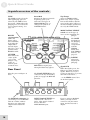
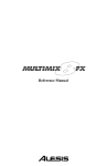
A quick overview of the controls
TYPE
The TYPE switch selects the
kind of flanging effect, as
shown by the LEDs next to
the switch. TYPE affects the
flanging tone, as well as the
stereo output routing. See
page 32.
Reset Mod
Restarts the flanger from the
beginning of its cycle.
Generates a trigger in
TRIGGERED mode, or
changes the pattern in
PATTERN mode.
MODULATION SELECT
switch selects the type of
wave used to modulate the
flanger.
REGEN
(regeneration)
makes the
flange effect
more dramatic,
by feeding the
output back
into the input.
The 12 o’clock
position turns
REGEN OFF.
CENTER
Determines the
center of the
cycle of the
flanger—top,
center or
bottom of the
scanned area.
The RATE
knob affects
the flanging
speed, in
cooperation
with the
TEMPO
SYNC and
TAP TEMPO
buttons. See
page35..
DEPTH
affects the
depth of the
flanging.
BYPASS lets signal pass
through without any effects.
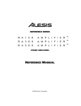
Rear Panel
Plug the power adapter in
here.
The ModLink connectors let
you arrange several ModFX
units in a chain, without
having to use input and
output cables inside the
chain.
16
Tap Tempo
Active in TEMPO SYNC
mode only. Tap a regular
beat on this button, and the
speed of the effect will be set
at some multiple of that beat,
as set by the RATE knobs.
The FOOT SWITCH may be
connected to any momentary
pedal, to engage the BYPASS
function.
INPUTS and OUTPUTS are
standard 1/4” line-level
jacks. Plug single-channel
devices into the
LEFT/MONO input.
Signal LED
When this lights green, the
Phlngr is getting an input
signal. When it’s red, it’s
seeing too much level, so turn
down the instrument ...
...or the TRIM control here
on the back panel.
If you’re using a ModLink
chain, you only need to
connect to the first unit’s
input, and the last unit’s
output.
2 Connections
Unpacking and Inspection
Your Phlngr was packed carefully at the factory. The shipping
carton was designed to protect the unit during shipping. Please
retain this container in the highly unlikely event that you need to
return the Phlngr for servicing.
The shipping carton should contain the following items:
•
•
•
Phlngr with the same serial number as shown on the
shipping carton
Power Adapter
This instruction manual
To register your purchase, go to the Alesis website at
www.alesis.com.
Installing in a Rack
The Phlngr is designed for tabletop use, but can also be installed
in a standard 19" audio equipment rack. For rack mounting,
contact your Alesis dealer for the ModFX Rack. This rack shelf
holds three ModFX units in a 3-space high 19” rack.
Power
The Phlngr comes with an AC power adapter that transforms
the voltage from a standard outlet into 9 volts AC (830 mA).
Plug the small end of the power adapter cord into the Phlngr’s
POWER INPUT socket and then plug the adapter itself into a
good quality, noise-free AC power source of the proper rating.
The supplied AC line adapter is designed only for the destination
to which the unit is shipped. To use the Phlngr in another
country, contact your Alesis dealer for an Alesis P3 adapter
suitable for the electrical system in the country you are traveling
to.
Make sure you read the
initial Important Safety
Instructions chapter at the
front of this manual.
Avoid “popping”:
Don’t plug the power adapter
into the Phlngr until all other
audio cables have been
hooked up. Make sure your
amplifier or powered
speakers are switched off
when plugging in the Phlngr
to avoid damage.
17
2
Connections
Connecting audio
The Phlngr will work in many different applications, whether you
are connecting an instrument directly into it, or connecting it
through a mixing console. But since the Phlngr is a stereo
effect unit, it’s important to know whether the source and/or
the system will be stereo or mono. The Phlngr is great for
taking a mono source and making it into a complex, layered
stereo signal, or it can take a stereo signal and flange each side
separately.
When connecting audio
cables and/or turning power
on and off, make sure that all
devices in your system are
turned off and the volume
controls are turned down.
Note that whenever a connection is made to the [RIGHT INPUT]
of the Phlngr, it will keep the outputs discrete (left to left, right to
right), unless the TYPE is set to DEEP MONO.
Mono In, Mono or Stereo Out
If you’re connecting a guitar or bass directly to the Phlngr, hook it
up this way:
1. Connect a 1/4" phone cord to the [LEFT/MONO] INPUT
of the Phlngr from any mono source. (The Left input will
then feed both outputs of the effect.)
2. Connect another 1/4" phone cord from the LEFT OUTPUT
of the Phlngr to the amp or mixer input.
3. If the amp or mixer is stereo, connect a second 1/4" phone
cord from the RIGHT OUTPUT of the Phlngr to the other
input of the stereo amplification system, or the next mixer
input.
4. If you’re connecting directly to a stereo mixer, pan the two
channels hard left and hard right to get the maximum effect.
18
Turn up the trim...
Most guitars and basses have
relatively low output levels.
For the quietest effect, turn
up the volume on the guitar to
full, then crank up the
[TRIM] control on the back
of the Phlngr until the
SIGNAL LED on its top panel
flashes red while you play,
then back it off a bit.
Connections
2
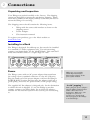
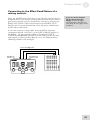
Connecting to the Channel Inserts of a
mixing console:
Most recording consoles have a jack near the mic and line inputs
labeled "Insert". This is typically a TRS jack with the send and
return on the same jack. To use the Phlngr as a channel insert, you
will need an insert cable (not included).
Ring:
Insert return
Tip:
Insert send
Sleeve:
Insert Ground
Insert SEND:
To ModFX INPUT
Insert RETURN:
From ModFX OUTPUT
This cable splits the TRS insert jack into two unbalanced mono
connectors. Usually, the tip is connected to the INPUT of the
Phlngr and the ring is connected to the OUTPUT of the Phlngr.
However, this may be reversed on some recording consoles.
Check your mixer’s Reference Manual to be sure or just try it both
ways – this won’t damage the Phlngr.
For stereo operation, you would use two insert cables, inserted
into two adjacent channels of the mixer. One would send and
receive signal to the left channel of the Phlngr, and the pan pot of
that mixer channel would normally be panned to the left. Pan the
next mixer channel, for the right side of the Phlngr, to the right.
19
2
Connections
Connecting to the Main Outputs of a mixing
console:
In addition to channel inserts, most mixing consoles have main
insert jacks near the main outputs. You can use insert cables to
connect the Phlngr to the main L/R bus the same way you
connect it to a pair of channels. Simply connect one insert cable
to the left main insert of the mixer, and connect the two mono
jacks to the left INPUT and OUTPUT of the Phlngr. Use another
insert cable to connect the right main insert to the right INPUT
and OUTPUT of the Phlngr.
Alternatively, you could plug the mixing console’s main outputs
directly into the Phlngr’s inputs, then feed the Phlngr’s outputs to
your monitor amps or mixdown recorder. However, if you fade
down the volume at the end of the song, the sound quality may
change as you fade. This is why it’s better to use the insert jacks, if
available.
20
Connections
2
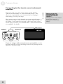
Connecting to the Effect Send/Return of a
mixing console:
Since the ModFX boxes don’t have a wet/dry mix control, they’re
designed more for in-line processing than the send/receive kind of
processing typically used for reverb units. However, plugging the
Phlngr into a mixer’s effect send/return loop will allow you to
flange a mix of several instruments, from any mixer channel that
has its effect send raised.
If you use mixer channels
for the returns from the
Phlngr, be sure the Effect
Sends for those channels are
turned all the way off to avoid
feedback.
To do this, connect a single cable from the Effect Send Out
(sometimes labeled “Aux Out”) to the [LEFT/MONO] input of
the Phlngr. Use two separate cables to connect the [LEFT
OUTPUT] and [RIGHT OUTPUT] of the Phlngr to the left and
right inputs of a Stereo Effect Return, or to two adjacent mixer
channels panned to left and right.
From Aux/Eff Send
To returns
21
2
Connections
Connecting to the inserts on an instrument
amplifier:
The insert send on a guitar or bass amp is usually labeled
"effects send and return" or "insert send and return". This
allows you to preamplify your instrument before flanging it
and sending it to the power amp.
Most guitar amps are single channel, so connect a single insert
cable from the amp to the LEFT INPUT and LEFT OUTPUT of
the Phlngr. Some amps have separate “effect send” and “effect
return” jacks; for these, use standard cables. Check the manual of
your amplifier for details.
If you are using a dedicated rack-mount preamplifier, another
method would be to insert the Phlngr between the preamp and the
input(s) of the power amp.
22
Never connect the
Phlngr between the
power amp and the
speaker!
The high power levels created
by the power amp will
destroy the circuitry of the
Phlngr.
Connections
2
Connecting to equipment with XLR inputs
and outputs:
If you are connecting the Phlngr to a product with XLR balanced
inputs and outputs, you will need to convert this signal to a 1/4”
unbalanced connector. Make sure that Pin 2 of the XLR
connector is connected to the Tip of the 1/4” adapter or cable.
Watch out for high levels, however: some XLR sources put out
levels close to the maximum the Phlngr can accept (about +12
dBu) even when its trim is at minimum. Lower the level of the
source if the [SIGNAL] LED flashes red.
About audio cables
The connections between the Phlngr and your studio are your
music’s lifeline, so use only high quality cables. These should be
low-capacitance shielded cables with a stranded (not solid) internal
conductor and a low-resistance shield. Although quality cables
cost more, they do make a difference.
Don't use line
transformers:
Many XLR-to-1/4" adapters
sold at electronics stores are
NOT adapters, but
transformers (and very low
quality transformers at that).
Don't use these on the output
of the Phlngr—they're
unnecessary and generally
sound awful because they
don't have the headroom to
handle the Phlngr's output.
Get a hard-wired adapter or
cable from your professional
audio dealer, or make one
yourself from components.
Route cables to the Phlngr correctly by observing the following
precautions:
•
Do not bundle audio cables with AC power cords.
•
Avoid running audio cables near sources of
electromagnetic interference such as transformers,
monitors, computers, etc.
•
Do not place cables where they can be stepped on.
Stepping on a cable may not cause immediate damage,
but it can compress the insulation between the center
conductor and shield (degrading performance) or reduce
the cable’s reliability.
•
Avoid twisting the cable or having it make sharp, right
angle turns.
•
Never unplug a cable by pulling on the wire itself.
Always unplug by firmly grasping the body of the plug
and pulling directly outward.
23
2
Connections
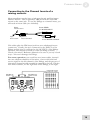
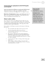
Using the ModLink
The Phlngr can be connected to other effect boxes in the ModFX
family via the ModLink. The ModLink is a cable-free connection
between two ModFX units that transfers digital audio and word
clock. The 9-pin male connector on the left side of the unit is the
ModLink IN port. The 9-pin female connector on the right side is
the ModLink OUT port. By directly connecting two ModFX units
via the ModLink, audio will pass from the left-most unit to the
right-most unit.
Inputs
Master
AC adapter
First Slave
Audio Flow
Outputs
Second Slave
The audio signal flows from left to right. The Master will send its
digital audio output to the First Slave, and the First Slave will, in
turn, send its output to the Second Slave.
24
What about the 1/4”
jacks on the slave
units?
When a unit is a slave to
another unit, its audio input
jacks are disabled; it will get
its audio input digitally from
its ModLink port. The output
jacks, however, are always
active; so an audio output
can be tapped from any
linked unit, without
interrupting the flow to the
rest of the chain.
3 Using the Phlngr
This section defines flanging, and explains the functions of the
Phlngr’s controls in greater detail. A little technical knowledge will
help you get the most out of your gear...it’s really pretty simple.
About flanging
In the 1960’s, when engineers had learned how to synchronize two
analog reel-to-reel tape recorders, someone discovered that if the
same audio was recorded on both recorders, and you deliberately
slowed one down by dragging your finger on the flange of one of
the tape reels, a deep comb-filtering effect happened as the
waveforms from each recorder drifted back and forth in time,
trying to lock together again. This jet-airplane-like sound became
famous on recordings by Jimi Hendrix, and the Small Faces.
Today, instead of on tape recorders, the audio is recorded in digital
memory. It gets played back a few milliseconds later, at a point
that varies according to the setting of an LFO (Low Frequency
Oscillator). This gives you total control of the flanging effect
(and, it’s a lot less hassle).
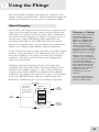
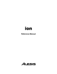
Flanging is achieved by delaying one part of the signal, then
varying the time delay with an LFO. The delayed signal is then
mixed with the original “straight” or “dry” sound, producing a
complex series of phase additions and subtractions at different
frequencies. By feeding back a part of the output of the delay line
to the input (REGEN), these frequency nodes become more
dramatic as oscillations begin to occur at different frequencies.
Flanging vs. Phasing
These two effects sometimes
sound alike, but they are
achieved in different ways.
Phasers use shifting filters;
flangers use shifting time
delays. In both cases, the
characteristic sound is
created by peaks and dips in
frequency response when the
shifted signal is recombined
with the unprocessed signal.
Flanging has a much more
complex series of additions
and cancellations (peaks and
troughs in the frequency
response) than phasing does.
It also slightly changes the
pitch of the sound, which
phasing doesn’t. Phasing’s
frequency nodes are
nonharmonic, and less
obtrusive.
Try out the Alesis Faze to
hear one of the best phase
shifters available today.
DRY SIGNAL
Left input feeds
both sides if
nothing’s plugged
into the RIGHT
jack
FEEDBACK
LEFT
FLANGED
OUTPUT
DELAY
DRY
SIGNAL
LFO
DELAY
FEEDBACK
RIGHT
FLANGED
OUTPUT
DRY SIGNAL
25
3
Using the Phlngr
How the controls work inside the flanger
Picture it this way: there’s a block of audio in delay memory
several milliseconds long, always being loaded with new audio
from the input jacks. A “pointer” picks up this audio at some
particular point in the delay for playback. If the pointer stays in
one place, it’s just a static delay line—and when you mix the veryslightly delayed output with the original input, you get a comb
filter (phase cancellations at certain frequencies, additions at
others). If you move the pointer back and forth in this block
quickly, the pitch will change: higher as it moves towards the start
of the block, lower as it moves towards the end of the block. This
also changes the shape of the frequency response, when it’s mixed
in with the original signal.
The [DEPTH] control sets how big the “block” of audio is, from
start to finish. The [RATE] control sets how quickly the playback
pointer runs from the start to the finish of the block and back
again. The Modulation Type (Triangle, Pattern, etc.) sets how
smoothly (or not) the pointer moves through the block. The
[CENTER] determines where the pointer starts—beginning, end
or center—at the start of a cycle. The [REGEN] control sets how
much of the output of the pointer is fed back to the input of the
block, and whether that output is in phase (+), or out of phase (-).
Flanging in stereo
Stereo source
When you have a left and right input plugged into the Phlngr, it
behaves like two separate flangers that are synchronized. If a
piano goes into the left input, it comes out of the left output,
flanged, without mixing with any signal going through the right
channel (unless the TYPE is set to DEEP MONO, see p. 33).
This discrete stereo operation is important for stereo instruments,
and if the Phlngr is part of a stereo effects chain (for example,
following an Ampliton in autopan mode).
Mono source
But, mono sources can be transformed into a pulsating stereo
signal when they’re connected to the LEFT/MONO input to
achieve a particular dramatic effect. If nothing’s connected to the
right input, the LEFT input is automatically sent to both left and
right flangers. If you set the TYPE switch to CONTRARY
STEREO or ASYNC STEREO, the different outputs of the two
sides will broaden the stereo perspective from any mono source.
Especially for listeners on headphones, the result can be quite
dramatic.
26
Using the Phlngr
3
What is Tempo Sync?
Flanging occurs over time. Sometimes, you’ll want the rate of the
effect to match the beat of your music instead of being random.
For example, you can set the rate so that the flange effect
completes each cycle once per measure, or to a vibrato-like effect
that happens in sixteenth notes. The TEMPO SYNC feature of
the Alesis ModFX series not only lets you set a tempo naturally by
tapping on the TAP TEMPO button, it can automatically adjust its
speed slightly relative to the beat of the incoming audio signal,
after setting the basic speed using the TAP button.
To use Tempo Sync:
You can set the Phlngr to TEMPO SYNC mode as follows:
1. Press the down side of the [MODULATION] rocker switch to
select the next modulation type.
You can see the type of effect by the LED lit next to the name—for
example, TRIANGLE, HYPER TRI, TRIGGERED and so on.
2. Keep pressing the rocker switch through all the normal modes
until you enter TEMPO SYNC mode, and then advance to the
type of modulation you want.
Both the Mod Type and TEMPO SYNC LEDs will be lit. For
example, if you press the down side of the rocker switch when you’re in
PATTERN mode, the Phlngr will go to TRIANGLE/TEMPO
SYNC mode. At this point, the TAP TEMPO LED will start
flashing at the last speed it was set at (or will light solid, indicating that
no tempo has been set since the unit was turned on).
3. Tap the [TAP TEMPO] button several times to set the desired
tempo.
The TAP TEMPO LED will flash in time to the hits. As long as
the [RATE] control is in the center position, the flanging speed will
match the tempo.
4. If the tempo isn’t quite right, “tap” a steady, discrete beat on
any instrument connected to the input. The internal processor
will then synchronize the tapped tempo with the audio input.
The processor will make slight alterations to the tempo such
that it stays synchronized with the beat of the audio input.
The RATE knob is
different in Tempo
sync mode
In TEMPO SYNC mode, the
RATE knob acts as a
multiplier to the speed set by
TAP TEMPO, so you can’t
get the tempo to change
slightly by adjusting that
knob. Note that changes to
RATE won’t affect the
flashing of the TEMPO LED.
To turn Tempo Sync off:
Simply press the UP side of the [MODULATION] switch
repeatedly until the Tempo Sync LED goes off, then select the
modulation waveform you want.
27
3
Using the Phlngr
Description of Controls
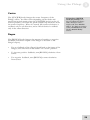
Rate
The [RATE] knob changes the flanging modulation speed.
In normal modulation modes (TEMPO SYNC LED off), turning
the [RATE] knob alters the rate continuously from very slow to
very fast. Turn the knob clockwise for a faster speed, counterclockwise for a classically-slow sweep.
Rate knob operation in TEMPO SYNC mode
When the Phlngr is in TEMPO SYNC mode, the fundamental
modulation speed is set by the TAP TEMPO function, and the
rate knob can be used to adjust that rate to an even fraction or
multiple of the current tempo:
• With the knob indicator in the 12 o’clock position, the mod
rate will be the same as tempo (i.e, quarter note).
• Turn the knob to the left to set the mod rate at a half of the
tempo (i.e., one cycle per half note), then a quarter of the
tempo (once per measure).
• Turn the knob to the right (clockwise) to set the modulation
to twice the tempo (eighth notes), or four times the tempo
(sixteenth notes).
See the description of
TAP TEMPO for
important tips on using
this feature.
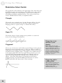
The diagram below shows where you can set the [RATE] knob to
modulate the flanger at different multiples of the tempo during
TEMPO SYNC mode.
Adjust Rate and
Depth together
Depth
The [DEPTH] knob changes the intensity of the flanging effect,
by increasing the total delay time region that the flange “scans”.
[DEPTH] interacts considerably with the [RATE] control (see next
page). Low [DEPTH] settings are very subtle, unless the [RATE]
is set high. Turn the knob clockwise for a deeper effect. Turning
[DEPTH] all the way counter-clockwise turns flanging off
completely.
28
Generally, you’ll find if you
adjust one of these controls,
you’ll have to adjust the other
one to compensate. A high
rate sounds best with a low
depth, and vice-versa.
Using the Phlngr
3
Center
The [CENTER] knob changes the center frequency of the
Phlngr’s effect. Its effect varies depending on the mode and
speed, but in pitch terms, when the [CENTER] knob is at the 12
o’clock position, you’ll hear the pitch oscillates up and down from
the center frequency. When it’s turned full counter-clockwise, it
oscillates only in one direction, and at full clockwise it oscillates
only in the other direction.
To hear how CENTER
works for yourself, set a
deep, medium-rate flange
with a Triangle source,
maybe with some REGEN
added. Try different settings
of the [CENTER] knob, and
tap the [RESET MOD]
switch.
Regen
The [REGEN] knob changes the amount of positive or negative
feedback (how much output of the flanger is fed back to the
flanger’s input).
•
For no feedback of the flanged signal back to the input of the
flanger, leave this knob in the center “12 o’clock” position.
•
To increase positive feedback, turn [REGEN] clockwise from
center.
•
For negative feedback, turn [REGEN] counter-clockwise
from center.
29
3
Using the Phlngr
Modulation Select Switch
The up/down rocker switch on the right side of the unit selects the
modulation source for the flanger. The LEDs next to the switch
light up to indicate the current mode. There are five kinds of
modulation available, explained below. The rocker switch also
selects TEMPO SYNC mode, as explained earlier.
Triangle
This mode uses a triangle wave for the flanging effect. Use this
when you want the smooth up-and-down cycle of traditional
flanging (such as a “space sweep” or vibrato-like effect).
Hyper Tri
This mode selects a hyper triangle wave (similar to a sawtooth
wave) for the flanger’s modulation.
Triggered
This is one of the most useful effects in the Phlngr for live players.
Instead of using a repeating wave or LFO, the flange is held at a
single point (no flange) until a trigger happens, then it scans across
the block before stopping again. A trigger is any sudden increase
in the input audio level. So, if you play a heavy accent on a note,
the signal will flange on that note, then the flanging will stop
again. Pressing the [RESET MOD] button will also cause a
trigger. Note that since there’s no repeating waveform in
Triggered mode, the [TAP TEMPO] features have no effect.
[RATE] will affect the decay time of the envelope.
Triggering reacts
directly to your
playing
With a little practice and
some careful level adjustment
of your instrument, you’ll
adjust to the feel of how loud
you have to play to generate
a trigger and start a flange,
and how soft to play to keep
the flange “frozen”.
Triggering with a
volume pedal
With sustained sounds, you
can trigger the flanger by
using a volume pedal, or the
volume knob on the
instrument itself. Try it!
30
Using the Phlngr
3
Uncertainty
This mode randomly generates a continually altering waveform for
the flange modulation, changing direction at various points during
the cycle.
Pattern
This mode randomly generates a 16-step sequence to modulate the
flange and repeats it over and over. Instead of gliding through the
frequency range, Pattern mode sometimes makes the flanger jump
quickly from step to step, while other levels “glide” from step to
step. It sounds somewhat like the “sample and hold” modulation
of a synchronized oscillator on a synthesizer, except that the
pattern will step through the same 16 steps over and over, instead
of being random.
•
Press the [RESET MOD] button to generate a new 16-step
pattern.
•
Try using the [RATE] knob, or the TEMPO SYNC/TAP
TEMPO features, to make the steps of the pattern play in
sync with your music. Keep in mind that the pattern has 16
steps per 4 beats, so adjust the RATE knob accordingly.
If the [REGEN] control is
turned all the way up in
PATTERN mode and you
play a single, sustained tone,
you’ll hear a sample-andhold-like sequence of tones
against that tone.
RATE in Pattern
mode
You can think of Pattern
mode as being 4x the rate of
the other modulation sources.
In Tempo Sync mode, turn the
[RATE] knob full clockwise
(1/4 speed) to get one step
per beat, the same as
Triangle at a 12 o’clock
setting of [RATE].
31
3
Using the Phlngr
TYPE Rocker Switch
The up/down rocker switch on the left side of the unit selects the
Phlngr’s flanging algorithm—in other words, the timbre and how
its left and right signal paths relate to each other. The difference
between several types is most dramatic when the OUTPUTS are
connected in stereo, although the TYPE switch will have an
audible effect even in mono systems. The LEDs next to the
switch light up to indicate the current mode. There are five
flanging types available, explained below.
Stereo
In STEREO mode, the left and right channels are synchronized
exactly. As the flange sweeps down on the left, it sweeps down on
the right simultaneously.
Contrary Stereo
In CONTRARY STEREO mode, the left and right channels of
the Phlngr are synchronized, but travel in opposite directions: as
the left channel flanges downwards, the right channel flanges
upwards.
Async Stereo
In ASYNC (asynchronous) STEREO mode, the modulation of the
left and right channels of the Phlngr are not synchronized. The
left and right channels will have a similar rate, but “drift” from
each other in a random way (except in Pattern mode, where they’ll
be related to each other).
32
Using a mono source?
If you’re plugging a mono
source like a guitar into the
LEFT/MONO input only, but
still have a stereo output,
you’ll find that CONTRARY
STEREO mode gives a stereo
effect, while STEREO mode
sounds centered between the
speakers because the two
channels are in sync.
Using the Phlngr
3
Through Zero
This mode delays the input signal to better simulate tape flanging.
When flanging was done using two tape machines, it was possible
for one to be behind the other, catch up and then go past the
other. This is called “passing through zero”, the “zero” point
being when both signals were in perfect sync. As the flange passes
close to zero, there’s a point where the sound almost vanishes
completely as the two signals are out of phase.
Since the Phlngr is digitally simulating the flanging effect (and
normally can’t “go past” the input signal coming in in real time),
this mode delays the unprocessed “dry” signal by as much as 12
milliseconds. This small delay is virtually undetectable to the ear,
but it allows the flanged signal to move “behind” the dry signal as
it cycles.
If you’re using an
effect send...
In Through Zero mode, mute
any “dry” signal path
through the console. Let the
Phlngr handle the wet/dry
mix. Otherwise, you’ll hear a
fixed hollow kind of sound
resulting from the delay of the
dry signal through the Phlngr
mixing with the undelayed
signal.
Deep Mono
If you’ve cranked up the [DEPTH] control all the way, but still
aren’t getting the dramatic flange effect you’re looking for, try
DEEP MONO. This mode sums the left and right channels
together, so it can use both sides of the Phlngr’s digital memory to
provide a block of sound to scan that’s twice as long as in any of
the previous modes. Even at slow [RATE] settings, there can be a
dramatic pitch-shifting effect in this mode, so it’s particularly
useful when you want a slow flange. Usually, you’ll need to reduce
the [DEPTH] control in this mode.
33
3
Using the Phlngr
Reset Mod
Press this button to reset the phase of the flanger modulation
source as follows:
• In TRIANGLE, HYPER TRI, and UNCERTAINTY modes,
press [RESET MOD] to start the wave from the beginning of
its phase.
The “starting point” of the wave in digital memory is determined by the
setting of the [CENTER] control
• In TRIGGERED mode press this button to generate a trigger
for the modulation (momentarily flanging across the memory,
then stopping).
• In PATTERN mode press this button to generate a new 16step pattern.
34
Using the Phlngr
3
Tap Tempo
This button affects the speed of the effect whenever the
[MODULATION] switch is set to a TEMPO SYNC mode. At
any time you can tap this button along with the music to set a new
tempo. The Tap Tempo light will flash at the current tempo.
Tap Tempo technique
For a reliable tempo setting, make from four to eight taps in a row
at a consistent speed, especially if you’re changing the tempo
drastically. Watch the flashing of the light to see the current
tempo of the Phlngr.
Adjusting tempo with audio input
After the basic tempo has been set using the [TAP TEMPO]
button, it is possible to make small adjustments to the tempo via
the audio input. You do this by “tapping” on the instrument
(playing sharp chords, or beats, without sustain or notes
inbetween) at almost the same speed as the Phlngr’s tempo LED,
or by slightly changing the speed of a drum machine feeding the
inputs. The Phlngr will automatically follow the beat from a
complex musical input, as long as it is reasonably close to the
original “tapped” tempo (it can adjust up or down about 5 beats
per minute from the tempo set on the [TAP TEMPO] button).
To get fast
modulations...
it isn’t necessary to tap at a
high speed if you want the
effect to modulate at eighth or
sixteenth notes. Just tap on
the quarter-note beat, then
turn the [RATE] knob to the
right to double or quadruple
the speed made by Tap
Tempo.
How Tap Tempo works with Tempo Sync and
the Rate knobs
When TEMPO SYNC mode is enabled, the rate of the modulation
will be based on the tempo currently being flashed, multiplied by
the position of its [RATE] knob: when it’s in the middle position
(around “12 o’clock”), the speed of the triangle, hyper tri or
uncertainty wave, or the pattern, will be the same as the tempo.
See the earlier descriptions of the [RATE] knob and Tempo Sync
for more information.
35
3
Using the Phlngr
Bypass
This button sends the signal directly from the input to the output
without any effect. Press [BYPASS] to check the sound of the
source without any effect from the Phlngr. When the red
BYPASS LED is lit, the flanging effect is off. The Bypass
function can also be activated by a footswitch.
Since the Phlngr is a digital effect, signal always passes through the
digital A/D–D/A conversion process, so that digital signal will
flow through to other effects in a ModLink chain even when
[BYPASS] is on. So, unlike old analog effects, this is not a
“hardwire” bypass switch—the Phlngr must be powered on to
pass signal through, even in bypass mode. Similarly, the [TRIM]
control is always active, since it’s an analog control regulating the
level feeding the analog-to-digital converters.
Using the Foot Switch
If you need to bypass the effect totally but your hands aren’t free,
simply connect any momentary footswitch (such as those used for
keyboard sustain pedals, either NC normally closed or NO
normally open) to the [FOOT SWITCH] jack on the rear panel.
The footswitch will turn the BYPASS LED on and off.
36
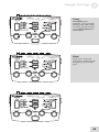
4 Sample Settings
While there’s nothing like discovering new sounds for yourself, we
thought it would be a good idea to provide some sample settings
of the Phlngr to help get you started. Simply set the knobs on
your Phlngr so they’re at the positions shown, and press the rocker
switches so each effect is in the mode shown by the LEDs. Feel
free to modify these any way you want to suit your particular
playing style.
Pattern Phlng
Flanges a complex pattern in
time with the rhythmic input.
Press [RESET MOD] to get a
different pattern, and set the
initial beat by tapping on
[TAP TEMPO].
Magic Motion
This setting makes good use
of the stereo capabilities of
the Phlngr. Using
UNCERTAINTY as the mod
source keeps the contrary
motion on the left and right
sides random.
37
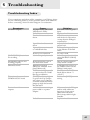
4
Sample Settings
Dual Jets
Another interesting setting for
stereo headphones; the left
and right sides will seem to
follow each other at varying
distances.
Zero Effect
Tap half notes in to this
patch, and the flange will
cycle once every two
measures. Turn the [RATE]
control clockwise to make it
cycle every measure; at “12
o’clock” it will cycle every
half note.
Supersonic
This is flanging taken to its
extreme, duplicating the long,
slow sweep first used in
classic recordings of the
1960’s. The TYPE is DEEP
MONO; and TRIANGLE or
HYPER TRI both are
interesting options. Tip:
Press [RESET MOD] to start
the cycle at the beginning on
cue.
38
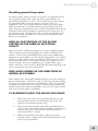
Sample Settings
4
Twang
With REGEN set to
maximum, it will sound like
plucking a big rubber band
each time you play a trigger.
Press [RESET MOD] for a
manual pluck.
Blank
Fill in your own favorite
settings here. Photocopy the
next page if you need more
space.
39
4
Sample Settings
Blank Settings Templates
40
5 Troubleshooting
Troubleshooting Index
If you experience problems while operating your Phlngr, please
use the following table to locate possible causes and solutions
before contacting Alesis Product Support for assistance.
Symptoms
No audio outputs.
Cause
No input audio (SIGNAL
LED doesn’t flash).
Bad cables.
Destination is turned
down.
Input Trim knob is turned
down
Input cables are connected
to a ModLink slave
[TAP TEMPO] button is
not working
ModLinked units are not
working properly
Distorted sound
Distortion when you leave
TEMPO SYNC mode
Buzz or hum from
outputs
Power is not connected
Not in Tempo Sync mode
Power dropout to one of
the units in the chain
Input level too high
(SIGNAL LED on front
panel flashes red)
RATE set at a high speed,
to a point where it sounds
like ring modulation
[RATE] knob is set high
to get 4x the Tap Tempo
rate; when you go back to
a normal mode, the RATE
jumps up high and sounds
like distortion
Audio cables are crossing a
power cable or a power
adapter.
Bad cables
Solution
Test with a known good
input.
Replace the cables.
Check the connections
and the level of the mixer
or amp that the Phlngr is
connected to.
Adjust the knob to the
proper level.
Connect the input cables
to the Master of the link
chain
Go take a walk
Select Tempo Sync mode
using [MODULATION]
switch.
Plug in a power supply to
every unit in a chain.
Turn down the source, or
the TRIM control on the
Phlngr’s back panel.
Turn down the RATE
knob (below about “3
o’clock”)
Reduce the [RATE]
setting
Make sure that the Phlngr
and its audio cables are
kept away from power
cables and wall warts.
Don’t wrap cable in tight
bundles.
Replace the cables
41
5
Troubleshooting
Symptoms
AC hum
42
Cause
Problem with the source
Ground loop
Solution
Try bypassing the Phlngr
by connecting the input
cables to the output cables
and see if the problem
remains.
Place all equipment in the
studio on a common
ground (see next page)
Troubleshooting
5
Avoiding ground loop noise
In today’s studio, where it seems every piece of equipment has its
own computer chip inside, there are many opportunities for
ground loop problems to occur. These show up as hums, buzzes
or sometimes radio reception and can occur if a piece of
equipment "sees" two or more different paths to ground. While
there are methods to virtually eliminate ground loops and stray
radio frequency interference, most of the professional methods are
expensive and involve installing a separate power source just for
the sound system. Alternatively, here are some helpful hints that
professional studio installers use to keep those stray hums and
buzzes to a minimum.
KEEP ALL ELECTRONICS OF THE SOUND
SYSTEM ON THE SAME AC ELECTRICAL
CIRCUIT.
Most stray hums and buzzes happen as a result of different parts
of the sound system being plugged into outlets of different AC
circuits. If any noise generating devices such as air conditioners,
refrigerators, neon lights, etc., are already plugged into one of these
circuits, you then have a perfect condition for stray buzzes. Since
most electronic devices of a sound system don’t require a lot of
current (except for power amplifiers), it’s usually safe to run a
multi-outlet box or two from a SINGLE wall outlet and plug in all
of the components of your system there.
KEEP AUDIO WIRING AS FAR AWAY FROM AC
WIRING AS POSSIBLE.
Many hums come from audio cabling being too near AC wiring or
power transformers. If a hum occurs, try moving the audio wiring
around to see if the hum ceases or diminishes. If it’s not possible
to separate the audio and AC wiring in some instances, make sure
that the audio wires don’t run parallel to any AC wire (they should
only cross at right angles, if possible).
TO ELIMINATE HUM IF THE ABOVE HAS FAILED:
1.
Disconnect the power from all outboard devices and
tape machines except for the Phlngr, the mixer and
control room monitor power amp.
2.
Plug in each tape machine and outboard effects device
one at a time. If possible, flip the polarity of the plug of
each device (turn it around in the socket) until the
quietest position is found.
3.
Make sure that all of the audio cables are in good
working order. Cables with a detached ground wire will
cause a very loud hum!!
43
5
Troubleshooting
4.
Keep all cables as short as possible, especially in
unbalanced circuits.
If the basic experiments don’t uncover the source of the problem,
consult your dealer or technician trained in proper studio
grounding techniques. In some cases, a "star grounding" scheme
must be used, with the mixer at the center of the star providing the
shield ground on telescoping shields, which do NOT connect to
the chassis ground of other equipment in the system.
Line conditioners and spike protectors
Although the Phlngr is designed to tolerate typical voltage
variations, in today’s world the voltage coming from the AC line
may contain spikes or transients. These can cause audible noises,
and they can stress your gear and, over time, possibly cause a
failure. There are three main ways to protect against this, listed in
ascending order of cost and complexity:
44
•
Line spike/surge protectors. Relatively inexpensive,
these are designed to protect against strong surges and
spikes, acting somewhat like fuses in that they need to
be replaced if they’ve been hit by an extremely strong
spike.
•
Line filters. These generally combine spike/surge
protection with filters that remove some line noise
(dimmer hash, transients from other appliances, etc.). A
good example is the Isobar™ series from Tripp Lite.
•
Uninterruptible power supply (UPS). This is the
most sophisticated option. A UPS provides power even
if the AC power line fails completely. Intended for
computer applications, a UPS allows you to complete an
orderly shutdown of a computer system in the event of a
power outage. In addition, the isolation it provides
from the power line minimizes all forms of
interference—spikes, noise, etc.
Troubleshooting
5
Care and Maintenance
Cleaning
Disconnect the AC cord, then use a damp cloth to clean the
Phlngr’s metal and plastic surfaces. For heavy dirt, use a nonabrasive household cleaner such as Formula 409™ or Fantastik™.
DO NOT SPRAY THE CLEANER DIRECTLY ONTO THE
FRONT OF THE UNIT AS IT MAY DESTROY THE
LUBRICANTS USED IN THE SWITCHES AND CONTROLS!
Spray onto a cloth, then use cloth to clean the unit.
Refer all servicing to Alesis
We believe that the Phlngr is one of the best signal processors that
can be made using current technology, and should provide years of
trouble-free use. However, should problems occur, DO NOT
attempt to service the unit yourself unless you have training and
experience. Service on this product should be performed by
qualified technicians only. NO USER-SERVICEABLE PARTS
INSIDE.
45
5
Troubleshooting
Obtaining repair service
Before contacting Alesis, check over all your connections, and
make sure you’ve read the manual.
Customers in the USA and Canada:
If the problem persists, contact Alesis and request the Product
Support department. Make sure you have the unit’s serial number
with you. Talk the problem over with one of our technicians; if
necessary, you will be given a return order (RO) number and
instructions on how to return the unit. All units must be shipped
prepaid and COD shipments will not be accepted.
For prompt service, indicate the RO number on the shipping label.
Units without an RO will not be accepted. If you do not have
the original packing, ship the unit in a sturdy carton, with shockabsorbing materials such as Styrofoam pellets (the kind without
CFCs, please) or "bubble-pack" surrounding the unit. Shipping
damage caused by inadequate packing is not covered by the Alesis
warranty.
Tape a note to the top of the unit describing the problem. Include
your name and a phone number where Alesis can contact you if
necessary, as well as instructions on where you want the product
returned. Alesis will pay for standard one-way shipping back to
you on any repair covered under the terms of this warranty. Nextday service is available for a surcharge. Field repairs are not
authorized during the warranty period, and repair attempts by
unqualified personnel may invalidate the warranty.
Customers outside the USA and Canada:
Contact your local Alesis distributor for any warranty assistance.
The Alesis Limited Warranty applies only to products sold to users
in the USA and Canada. Customers outside of the USA and
Canada are not covered by this Limited Warranty and may or may
not be covered by an independent distributor warranty in the
country of sale. Do not return products to the factory unless you
have been given specific instructions to do so.
46
Specifications
Audio Input
Input Connectors:
2 unbalanced 1/4” jacks
Maximum Input Level:
+10 dBV
Nominal Level:
-10 dBV
Input Impedance:
470kΩ
Input Converter Resolution:
24-bit, 48 kHz sampling
All measurements done over
a 22Hz – 22kHz range with a
1kHz sine wave at -1dBFS
input. Impedances are
measured at 1kHz.
Audio Output
Output Connectors:
2 unbalanced 1/4” jacks
Maximum Output Level:
+9 dBV
Output Impedance:
500Ω
Output Converter Resolution:
24-bit, 48 kHz sampling
Audio Performance
(Analog In to Analog Out)
Signal To Noise Ratio:
>100 dB A-weighted
THD+N:
< 0.005%
Frequency Response:
± 1dB from 22Hz to 22kHz
Internal DSP Resolution:
28-bit
Power Consumption:
7 Watts max (9VAC Alesis P3)
Mechanical
Size:
2.1” H x 5.8” W x 3.9” D
(53mm H x 148mm W x
98mm D)
Weight:
12.6oz. (357 g)
47
6
Specifications
This page intentionally left blank.
48
Index
amplifier, 21
ASYNC STEREO, 26, 32
BYPASS, 16, 35
with foot switch, 35
cables, 22
CENTER, 16, 29
effect on RESET MOD, 34
CONTRARY STEREO, 26, 32
Deep Mono, 33
DEPTH, 16, 28
interaction with RATE, 29
digital converters, 4, 35, 47
doppler effect, 29
DSP, 4, 47
Effect Send/Return, 20
feedback
controlled by REGEN
knob, 29
Flanging
defined, 25
stereo, 26
FOOT SWITCH, 16, 35
Ground Loop, 43
grounding, 7
guitar, 18
Hums and buzzes, 43
Hyper Tri, 30
INPUTS, 15
INPUTS and OUTPUTS, 16
Insert Cables, 18
levels, 22
LFO, 25
mixing console
hookup, 19
ModLink, 4, 5, 16, 23
MODULATION SELECT switch, 16, 30
Mono
sources, 26
OUTPUTS, 15
on ModLink slave units, 23
Pattern, 31
Phasing, 25
power adapter, 16, 17
Power cable, 7
Rack mounting, 17
radio/TV interference, 9
RATE, 16, 28
REGEN, 16, 25, 29
Reset Mod, 16, 34
in Triggered Mode, 30
Safety, 7
SIGNAL LED, 15, 16, 18, 22
stereo, 18
sources, 26
TYPE mode, 32
Tap Tempo, 16, 27, 34
Tempo Sync, 27
effect on RATE knob, 28
Through Zero, 33
transformers, 22
Triangle, 30
Triggered, 30
by RESET MOD, 34
TRIM, 15, 16, 18
active in bypass mode, 35
TYPE, 16, 32
Uncertainty, 31
XLR, 22
49
Warranty / Contact Alesis
Alesis Limited Warranty
ALESIS CORPORATION ("ALESIS") warrants this product to be free of defects
in material and workmanship for a period of one (1) year for parts and for a period of
one (1) year for labor from the date of original retail purchase. This warranty is
enforceable only by the original retail purchaser and cannot be transferred or assigned.
For the most effective service, the purchaser should register the purchase on the
ALESIS website at http://www.alesis.com/support/warranty.htm.
During the warranty period ALESIS shall, at its sole and absolute option, either repair
or replace free of charge any product that proves to be defective on inspection by
ALESIS or its authorized service representative. In all cases disputes concerning this
warranty shall be resolved as prescribed by law.
To obtain warranty service, the purchaser must first call or write ALESIS at the
address and telephone number available on the Alesis Website to obtain a Return
Authorization Number and instructions concerning where to return the unit for
service. All inquiries must be accompanied by a description of the problem. All
authorized returns must be sent to ALESIS or an authorized ALESIS repair facility
postage prepaid, insured and properly packaged. Proof of purchase must be
presented in the form of a bill of sale, canceled check or some other positive proof
that the product is within the warranty period. ALESIS reserves the right to update
any unit returned for repair. ALESIS reserves the right to change or improve design
of the product at any time without prior notice.
This warranty does not cover claims for damage due to abuse, neglect, alteration or
attempted repair by unauthorized personnel, and is limited to failures arising during
normal use that are due to defects in material or workmanship in the product.
THE ABOVE WARRANTIES ARE IN LIEU OF ANY OTHER
WARRANTIES OR REPRESENTATIONS WHETHER EXPRESS OR
IMPLIED OR OTHERWISE, WITH RESPECT TO THE PRODUCT, AND
SPECIFICALLY EXCLUDE ANY IMPLIED WARRANTIES OF FITNESS
FOR A PARTICULAR PURPOSE OR MERCHANTABILITY OR OTHER
IMPLIED WARRANTIES. Some states do not allow limitations on how long an
implied warranty lasts, so the above limitation may not apply to you.
IN NO EVENT WILL ALESIS BE LIABLE FOR INCIDENTAL,
CONSEQUENTIAL, INDIRECT OR OTHER DAMAGES RESULTING
FROM THE BREACH OF ANY EXPRESS OR IMPLIED WARRANTY,
INCLUDING, AMONG OTHER THINGS, DAMAGE TO PROPERTY,
DAMAGE BASED ON INCONVENIENCE OR ON LOSS OF USE OF THE
PRODUCT, AND, TO THE EXTENT PERMITTED BY LAW, DAMAGES
FOR PERSONAL INJURY. Some states do not allow the exclusion or limitation of
incidental or consequential damages, so the above limitation or exclusion may not
apply to you.
THIS CONTRACT SHALL BE GOVERNED BY THE INTERNAL LAWS
OF THE STATE OF CALIFORNIA WITHOUT REFERENCE TO
CONFLICTS OF LAWS. This warranty gives you specific legal rights, and you may
also have other rights required by law which vary from state to state.
This warranty only applies to products sold to purchasers in the United States of
America or Canada. The terms of this warranty and any obligations of Alesis under
this warranty shall apply only within the country of sale. Without limiting the
foregoing, repairs under this warranty shall be made only by a duly authorized Alesis
service representative in the country of sale. For warranty information in all other
countries please refer to your local distributor.
50
For more effective
service and product
update notices, please
register your Phlngr
online at:
http://www.alesis.com/
support/warranty.htm
Warranty/Contact Information
Alesis Contact Information
Alesis Studio Electronics
Los Angeles, CA USA
E-mail:
Website:
[email protected]
http://www.alesis.com
Alesis Phlngr Reference Manual
Revision 1.0 by Alex Souppa & Dan Tinen
Copyright 2002, Alesis. All rights reserved
Reproduction in whole or in part is prohibited. Specifications
subject to change without notice.
All trademarks are the property of their respective holders.
7-51-0114-A
8/2002
51