1
DpuScan 4.0
Special Scanner Options for
Scamax 2600 and 5000
Copyrights
© 1997-2003 J&K Imaging (Marietta, GA/USA) and Janich & Klass (Wuppertal, Germany). All rights
reserved. Printed in Germany.
The information contained in this documentation is the property of J&K Imaging and Janich & Klass.
Neither receipt nor possession hereof confers or transfers any right to reproduce or disclose any part
of the contents hereof, without the prior written consent of J&K Imaging and Janich & Klass.
Trademarks
DPU/DDU logos are registered trademarks of Janich & Klass. DpuScan is a trademark of J&K
Imaging. All other product names and logos are copyrighted and/or registered trademarks of their
respective companies.
Disclaimer
The instructions and descriptions in this manual were accurate at the time of this manual's printing.
However, we reserve the right to alter the description and/or the product at anytime without prior
notice.
J&K Imaging and Janich & Klass assume no liability for damages incurred directly or indirectly from
errors, omissions, or discrepancies between the manual and the product.
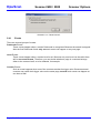
Actuality
A more recent version of the scanner options for DpuScan may be available for download from the
Internet. Therefore, it is recommended that you compare the version by means of the date printed on
this page with the version on the Internet. You should use the most up-to-date version.
The actual version of this addition to the DpuScan Reference Manual is found on the web at:
www.jkimaging.com/pdf/scanner options/Options-Scamax2600.pdf
© 2003 Janich & Klass Computertechnik GmbH, Wuppertal, Germany
July 25, 2003
Scanner Options
Scamax 2600 / 5000
DpuScan
Table of Contents
1
Description of the Scanner Options ................................................................................................ 5
1.1
Introduction.............................................................................................................................. 5
2
Device Properties ........................................................................................................................... 6
3
Image Processing Options.............................................................................................................. 9
4
Image Index .................................................................................................................................. 12
5
Expanded Endorser Control for Scamax 2600 ............................................................................. 15
5.1
What it is and How it Works................................................................................................... 15
5.2
Terms and Definitions............................................................................................................ 16
5.2.1
Header............................................................................................................................ 16
5.2.2
Image Address ............................................................................................................... 19
5.2.3
Counters......................................................................................................................... 19
5.2.4
Flags............................................................................................................................... 21
5.2.5
Level............................................................................................................................... 21
5.2.6
Mode .............................................................................................................................. 22
5.3
Parameter Configuration ....................................................................................................... 22
5.3.1
Patchcodes..................................................................................................................... 24
5.3.2
How to Set and to Trigger Counters ............................................................................... 25
5.3.3
How to Print Counters .................................................................................................... 27
5.3.4
Level and Mode Output – "Print Flags" Tab ................................................................... 29
5.3.5
Preview of Endorser and Header ................................................................................... 30
5.3.6
Save and Load Modes ................................................................................................... 32
5.4
Events and Actions................................................................................................................ 33
5.4.1
Events ............................................................................................................................ 34
5.4.2
Actions............................................................................................................................ 35
5.4.3
Course of Events and Actions ........................................................................................ 35
5.5
Defining the Rule ................................................................................................................... 38
5.5.1
Counter Handling ........................................................................................................... 38
5.5.2
Setting Flags And Level ................................................................................................. 39
5.5.3
Device Control................................................................................................................ 41
Page 3 of 42
DpuScan
Scamax 2600 / 5000
Scanner Options
Table of Illustrations
Illustration 1 – Inotec Properties Tab: Device ........................................................................................ 6
Illustration 2 – Inotec Options: Front Page ............................................................................................ 9
Illustration 3 – Inotec Options: Index ................................................................................................... 12
Illustration 4 – Current Counters.......................................................................................................... 13
Illustration 5 – Scanner Properties with Links to the Patchcode Controlled Index............................... 16
Illustration 6 – Counter Confirmation ................................................................................................... 21
Illustration 7 – Patchcodes .................................................................................................................. 23
Illustration 8 – Counter Modes............................................................................................................. 25
Illustration 9 – Print Counter ................................................................................................................ 27
Illustration 10 – Print Flags .................................................................................................................. 29
Illustration 11 – Enabling the Endorser................................................................................................ 31
Illustration 12 – Load and Save JMD-Files .......................................................................................... 32
Illustration 13 – NDX Rules Patch II .................................................................................................... 33
Illustration 14 – Reset Values?............................................................................................................ 34
Illustration 15 – Setting Flags and Level.............................................................................................. 39
Illustration 16 – Device Control............................................................................................................ 41
Page 4 of 42
Scanner Options
Scamax 2600 / 5000
1
Description of the Scanner Options
1.1
Introduction
DpuScan
This documentation is valid for the following scanners of the company InoTec:
•
Scamax 2600 / Scamax 2500
•
Scamax 5000
You must use the following driver:
jukscsi
The scanner is connected using a standard SCSI interface board, and an ASPI driver must be
installed.
This program module was developed to enable the user to set the special options of the Admis S31
scanner. The jukscsi driver from Janich & Klass forwards these settings to the scanner.
The special scanner settings are offered with the user interface, spread over several pages.
Page 5 of 42
DpuScan
2
Scamax 2600 / 5000
Scanner Options
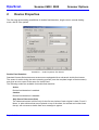
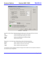
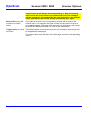
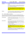
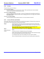
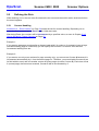
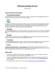
Device Properties
The first page gives setting possibilities for double feed detection, length control, manual feeding
mode, and fill color options.
Illustration 1 – Inotec Properties Tab: Device
Double Feed Detection
Standard Scamax Series document scanners are equipped with an ultrasonic double feed sensor.
The sensor is active during the entire scanning process (over the complete length of the document)
and gives an error report in the case of a double feed.
The following modes are available for double feed detection:
Active
Double feed detection is enabled.
Inactive
Double feed detection is disabled.
Only Start of Document (5cm)
The ultrasound sensor is active only for the first two inches of each original. Labels, Post-It
Notes, or other stickers that are not placed on top of the sheet, but at least two inches lower
the top, will not cause a double feed error message to appear.
Page 6 of 42
Scanner Options
Scamax 2600 / 5000
DpuScan
After Start of Document (5cm)
The ultrasound sensor becomes active only after the first two inches of each original. In
batches with different document types and very thin originals, a second sheet may feed too
deeply into the scanner, causing the sensor to report an error even though only one sheet was
fed and scanned.
In this mode, the above-mentioned event is unlikely to occur.
Reduced
The sensor will react only after a certain length of a detected double feed. These lengths
depend on the set paper size. Smaller stickers and labels do not automatically lead to a
double feed error message.
No Length Control
Normally, the scanner will use the length of the set paper size (paper format) in order to determine
when a sheet reaches its end. If the camera still captures paper after the defined paper length, it may
be caused by a document that is too long (larger than the set paper format), a staggered double feed,
or an extreme skew of the document. In such a case, the device will report an error.
On the other hand, if the paper is shorter than the expected format, the device will continue to scan
until enough image lines come together to result in an image of the desired format length. The
additional images lines are usually displayed in black. It is not filled up mathematically, so that the Fill
Color function has no influence here. Only when the image is complete will the next document feed
through the scanner. Thus, scanning a smaller original document will take the same amount of time
that it takes to scan an original with the defined paper format. The Deskew and Cropping functions
can be enabled.
If the length control is disabled (its box is checked), the device will scan in the defined paper format
length at a maximum, without regard as to whether the original is longer. Documents over this defined
length will be cut to match the defined format length (eventually creating an information loss) and the
double feed detection by paper length control will not be active. If, however, the paper is shorter than
the defined format length, the scanner will fill up the rest of the image mathematically to meet the
defined format length using the function Fillcolor on overlength. When the paper is shorter than
expected, there will be a gain in speed, because the next original is immediately fed and scanned
after the smaller original document.
Manually
Delayed feeder-empty-message for hand feeding
A sensor is located at the paper feeder of the scanner that reports "no paper" or "paper available" to
the scan application. If a paper batch is scanned and the last sheet is fed, the sensor reports "no
paper" to the software. The feeder rollers will then stand still and are reactivated only when new paper
is fed and a new scan command is given by the scan application.
If originals cannot be processed from the batch, it is possible to switch the scanner to manual feed by
means of the Manually function. Then, the scanner will no longer report "no paper" to the scan
application until there is a timeout of eight seconds. During this time, the feeder rollers continue
rolling, allowing fast and efficient scanning with the manual feeder.
Page 7 of 42
DpuScan
Scamax 2600 / 5000
Scanner Options
Please make sure the single sheet processor is switched on at the scanner.
Another possibility to effectively work with the manual feeder is the "Ignore paper status" function on
the Options property tab.
Fillcolor on Underlength
This parameter determines the fill color with which the missing length of an image that is shorter than
the defined paper length. This function can be executed only if "No Length Control" is enabled and if
the borders of the image are not cut. (Function: Border Cropping).
With a duplex scanner, this fill color is valid for the front side of a document and the back side.
Fillcolor on Deskew
This parameter determines the fill color for missing parts of an image due to a document skew and
automatic alignment.
With a duplex scanner, this fill color is valid for the front side of a document and the back side.
Roller Cleaning
The transport rolls of the machine should always be cleaned when the scanner no longer feeds the
paper from the batch.
To clean the rollers, take a fluff-free cloth or piece of paper and use the recommended cleaning liquid.
After starting the process, press the cloth to the underside of the feed rollers.
After pressing the Roller Cleaning button, a dialog appears that allows the user to start and stop the
process.
White Calibration
White calibration is required to compensate for differences in brightness that arise in the optical
transmission system. The calibration is made at the factory site, but it is also recommended in
situations when:
• a new lamp has been mounted in the scanner, or
• there are "stripes” and differences in brightness that are not caused by normal pollution of the
machine during the production process. Please make sure to clean the scanner before starting any
calibration.
The calibration is best made with the special white calibration sheets that were shipped together with
the machine. Put the calibration sheet into the feeder and press the calibration button.
Another dialog appears to start the process.
The process cannot be interrupted, and takes about ninety seconds to complete.
When the calibration is completed, a corresponding message dialog appears. Please restart the
scanner after every white calibration.
Page 8 of 42
Scanner Options
3
Scamax 2600 / 5000
DpuScan
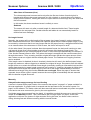
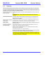
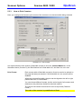
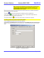
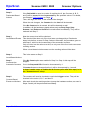
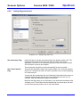
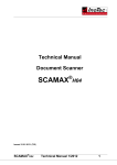
Image Processing Options
To optimize image quality you can set different image processing parameters. They are offered on the
next two pages, separately for Front and Back camera.
Illustration 2 – Inotec Options: Front Page
Binarization Method
The binarization method defines how the 256 possible grayscale values that come from the camera
will be transformed into bitonal information (black and/or white pixels).
Fixed Threshold
One of the 256 grayscale values is defined as the fixed threshold for the brightness. All levels
above will be represented as ”white”, and all others will be represented as ”black”. This simple
method is suited for "normal" documents without special colors, stains, or bad print.
Recommended Value: Brightness = 165
Automatic Threshold (one-dimensional)
The changes in gray levels in one line of the image are used to decide what is black and what is
white.
When deciding black or white, the scanner considers the previously read values of an image
line. Depending on the contrast settings, deviation levels in the grayscale values are considered
for the black/white decision dynamically.
Recommended Value: Brightness = 165; Contrast = 4
Page 9 of 42
DpuScan
Scamax 2600 / 5000
Scanner Options
DTplus Threshold (two-dimensional)
If the scanner has the DTplus board (optional), several image lines can be considered for the
black/white decision. As with the Automatic Threshold, not only the value itself, but also
deviations in its surroundings are considered.
The setting for brightness serves as the threshold for areas, and the setting for Contrast as the
sensitivity level for graylevel differences.
Recommended Values: Brightness = 165; Contrast = 12
Contrast
The contrast value defines the sensitivity for graylevel changes at neighboring pixels that will lead to
an interpretation of black or white. The lower the contrast, the higher the sensitivity level of the
scanner for graylevel changes.
For the automatic threshold, the Contrast can be set in 8 levels of sensitivity
Recommended Value = 4
If the device features a DTplus board, the two-dimensional DTplus threshold can also be used. Here,
127 theoretical sensitivity levels are available, but sensible settings are in the range between 5 and 25
Recommended Value = 12
Brightness
The brightness can be freely selected between values of 0 to 255. This represents the 256 graylevels
that the camera can capture. Sensible settings lie, as per the threshold method, between the values
of 120 and 180.
With the binarization method "Fixed Threshold", the brightness assumes a graylevel value between 0
and 255 as the limit from where the scan result for a pixel will be white or black.
Recommended Value = 165.
With the "Automatic Threshold", the brightness only serves as a threshold for the start value (white or
black) of every scan line.
Recommended Value = 165
With the binarization method "DTplus Threshold", the setting for brightness controls represents which
gray value will be represented as black or as white.
Recommended Value = 165
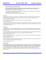
DTplus Filter
With the DTplus option, filters are available to reduce unwanted pixel "noise". The filter deletes black
and white pixels (despeck function) immediately after scanning, and even before the image is saved.
The table below lists the 60 possible values for the filter. With the value of 0, pixels will not be filtered
out at all. With the value of 1, black specks of 1x1 pixel are deleted. With the value of 16, black
specks of 4x2 pixels size are deleted, and all white specks of 1x1 pixel size (within black areas) are
filled with black.
Page 10 of 42
Scanner Options
Scamax 2600 / 5000
DpuScan
For improved barcode reading, and for results at scan resolutions of any level other than 200 dpi, we
recommend that the user selects their settings using notchfilter (values 30 to 59).
Delete
Color/Size
B / no
B / 1x1
B / 2x2
B / 3x3
B / 4x4
B / 4x1
B / 4x2
B / 1x4
B / 2x4
B / 3x2
Without Notchfilter
W / 1x1 W / 2x2
W/
0
10
20
1
11
21
2
12
22
3
13
23
4
14
24
5
15
25
6
16
26
7
17
27
8
18
28
9
19
29
W/
30
31
32
33
34
35
36
37
38
39
With Notchfilter
W / 1x1 W / 2x2
40
50
41
51
42
52
43
53
44
54
45
55
46
56
47
57
48
58
49
59
B = Black; W = White
Tracker for Brightness
This tracker can be enabled only if the scanner is equipped with a DTplus board.
The DTplus board also works with a background tracker. It calculates the gray value of the
background, using several scan lines.
When enabling the "Use Tracker for Brightness" function, the brightness is adjusted to the gray value
of the background, as evaluated by the background tracker, and is reregulated continuously during
several scan lines. This dynamic adjustment of brightness should be added for mixed documents if
their backgrounds have distinctly different colors (white, green, rose, gray, blue, etc.).
Tracker for Contrast
This tracker can be enabled only if the scanner is equipped with a DTplus board.
The DTplus board also works with a background tracker. It calculates the gray value of the
background, using several scan lines.
When enabling the "Use Tracker for Contrast" function, the contrast value is dynamically reregulated
with more sensitivity. The darker the gray value of the background has been calculated by the
background tracker, the lower the value. Because black text on a dark background results in a lower
gray value difference, the scanner will react more sensitively in this case. As with the "Use Tracker for
Brightness” function, this function is advised for mixed document batches with distinctly different
background colors.
Page 11 of 42
DpuScan
4
Scamax 2600 / 5000
Scanner Options
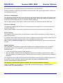
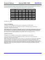
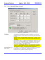
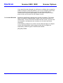
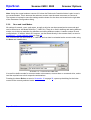
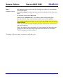
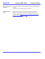
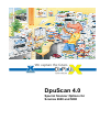
Image Index
If the device is equipped with the corresponding option, a header is created for each image. This
header may be used for indexing.
Illustration 3 – Inotec Options: Index
Refresh
Click the Refresh button to get and display the latest Image Header from the scanner.
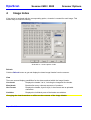
View
There are several display possibilities for the data contained within the Image Header:
Line break
Displays the header "as is", including the integrated line breaks.
Word break
Breaks after every coherent sequence of numbers.
Hex Format
Displays the header, byte for byte, in hex format and as printable
characters.
Variables
Displays the individual parts of the header as variables.
Changing the view format has no effect on the contents of the Image Header.
Page 12 of 42
Scanner Options
Scamax 2600 / 5000
DpuScan
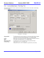
Mode
The mode is a combination of all settings made for Patchcode recognition, for counter behavior, for
endorser output, and for the rules to control the counters. This option allows the user to select from
one of the 16 operating modes.
To load, to change, and to save a mode, the user has to use the module Patchcode Controlled
Index, which you can reach by pressing the Configuration button.
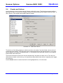
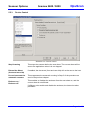
Confirm
The driver permanently stores the counter positions. This way, they can be used continuously, as well
as after longer breaks. Use the following dialog to confirm the current counter position, which you can
reach by clicking the Counters button. The dropdown list allows you to determine when this dialog
shall display automatically:
• Never
• On every scan job start
• Only after an error occurs
Illustration 4 – Current Counters
The Index Counters
Up to four counters can be used, depending on the kind of documents to be scanned:
Counter A
”Sheet counter”
Counter B
”Chapter counter”
Counter C
”Volume counter”
Counter D
”Film Roll number”
Page 13 of 42
DpuScan
Scamax 2600 / 5000
Scanner Options
If the counters are correspondingly set and enabled in the module Patchcode-Controlled Index, they
will be set and incremented as per the defined rules. So, for example, a document with the Patchcode
”Patch I” can indicate a new chapter. The chapter counter value increases incrementally by one and
the sheet counter is reset to zero.
The Index Flags
There are two flags that can be set for a sheet:
The latched flag remains set until it is reset, manually or via a defined Rule.
It can, for example, indicate that certain sheets are addenda to a certain form.
The momentary flag is valid only for the next sheet; it is then automatically reset.
You can use it, for example, to mark only the first document ("main document") of a new batch.
Document Level
The module uses the document level for Patchcode-Controlled Index, for example, to control
document separation.
Sequential ID
The scanner assigns a sequential number to the scanned sheets. This number usually cannot be
modified by a rule from the Patchcode-Controlled Index.
Exception: The sheet is "voided” or "not counted”.
Page 14 of 42
Scanner Options
Scamax 2600 / 5000
DpuScan
5
Expanded Endorser Control for Scamax 2600
5.1
What it is and How it Works
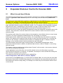
The Patchcode Controlled Index by Janich & Klass is intended as a method to control the scanning
process, to generate a data structure specific for each image, and simultaneously endorse the
paper.
The Patchcode Controlled Index requires an Agfa Admis S31 with SCSI firmware version 0.131
or higher. For printing on scanned documents the endorser must be built-in.
It is normally very difficult for a scan application to find out what a built-in endorser has printed on the
page, especially when the scanner works with a buffer. It is, for example, fairly impossible to change
the printout for page 11 depending on the information on page 10 that just comes right out of the
buffer, because by the time this has happened, the scanner is already at page 15 or 16.
A solution for this is to make the decision just before the new scan (and print) command is sent to the
machine. That works with a Janich & Klass SCSI scanner interface, which is mounted in several
scanner models.
The interface itself utilizes five counters that are incremented by user-defined values on every image.
Therefore, it is easy to change the endorsement every 100 images, for example.
Patchcodes are fast, reliable, and easy to identify, so it is ideal when they are printed on separator
sheets. The interface can recognize it fast enough to control the further process (e.g. to change the
printout for the endorser, to set/reset some counters, to drop/skip the page, or simply to stop the
scanner), on the condition that the code is printed at the top of the page.
The SCSI Interface sends the image to the host where it is handled by the application. When
Patchcode Controlled Index is utilized, an additional data structure, called a "Header", is sent along
with each image.
This header contains everything the interface board "knows" at this moment - the counters, date and
time, and the recognized Patchcode.
A scan application such as DpuScan can read this header and use its information to generate
directory and file structures. In summary, it is possible, for example, to name all files with exactly the
same text that is printed by the endorser.
To be able to print at all, the endorser must be enabled first:
Class Configuration | Data Source | Scanner | Options
At the bottom of the Options page, you will find the box labeled Text. You must enter the code %%I
Because the Patchcode Controlled Index depends on the hardware, the setup dialog for the Index is
found within the scanner’s setup dialog. For example, the Index setup for the Scamax 2600 is found
on the last tab.
Page 15 of 42
DpuScan
Scamax 2600 / 5000
Scanner Options
Illustration 5 – Scanner Properties with Links to the Patchcode Controlled Index
Note: If the required software modules are not installed, the button and the dropdown list for the
modes will not appear. When the scanner has the required hardware, the "Index" page is shown.
5.2
Terms and Definitions
Before we go to the configuration, we will take a look on some terms often used in this text:
5.2.1
Header
The header is the data structure, 512 bytes long, that is sent along with each image from the scanner
interface to the host. It is composed as per the following table:
0
1
2
3
4
F
r
o
n
t
18
19
20
21
22
23
L
e
n
g
t
h
37
38
39
40
41
42
L
e
v
e
l
Page 16 of 42
5
6
7
8
9
10
11
12
13
14
15
16
#
-
-
-
-
-
-
-
-
-
0
24
25
26
27
88
29
30
31
32
33
34
-
-
-
-
-
-
-
0
45
46
47
-
0
=
43
=
44
17
35
36
Scanner Options
48
49
50
51
52
M
o
d
e
=
57
58
59
60
61
L
i
n
e
81
82
83
84
P
a
g
e
85
53
54
55
56
-
0
lf
62
63
64
65
66
67
L
e
n
g
t
h
86
87
88
89
90
91
L
e
n
g
t
h
...
104 105 106 107 108 109
I
A
=
-
...
-
DpuScan
Scamax 2600 / 5000
118 119 120
0
.
-
-
68
69
70
71
72
73
74
75
76
77
78
-
-
-
-
-
-
-
0
95
96
97
98
99
=
-
-
-
-
-
129 130 131
...
=
92
0
93
.
94
-
-
140 141 142
0
.
-
...
-
79
80
100 101 102 103
-
-
0
lf
151 152 153
0
154 155 156 157 158
-
0
-
0
lf
159 160 161 162 163 164 165 166 167
C
m
p
=
-
0
168 169 170 171 172 173 174 175 176 177 178 179 180 181
D
a
t
e
=
m
m
d
d
y
y
182 183 184 184 186 187 188 189 190 191 192 193 194 195
T
i
m
e
=
h
h
m
m
s
s
196 197 198 199 200 201 202 203 204 205 206 207 208 209 210 211 212 213 214 215
R
o
l
l
#
=
-
-
-
-
-
-
-
-
-
0
216 217 218 219 220 221 222 223
R
e
s
=
-
-
0
224 225 226 227 228 229
B
o
=
-
0
230 231 232 233 234 235 236 237 238
S
k
=
239
...
255
nu
nu
nu
-
-
-
0
lf
------------------------------------------------------------------------------------------------------------------------
256 257 258
:
lf
nu
...
287
nu
nu
Page 17 of 42
DpuScan
Scamax 2600 / 5000
Scanner Options
288 289 290 291 292 293 294 295
R
e
v
=
-
0
296 297 298 299 300 301 302 303 304 305 306 307 308
I
A
_
F
i
x
_
e
x
t
=
-
...
-
322 323
-
324 325 326 327 328 329 330 331 332 333 334 335 336 337
P
a
t
c
h
c
o
d
e
=
-
0
338 339 340 341 342 343 344 345 346 347 348 349 350
E
n
d
351
...
511
nu
nu
nu
o
r
s
e
d
=
-
0
Note:
This view uses the following measurements:
Length
Image size in bytes
Level
In range 0 to 3
Mode
In range 0 to 15
LineLength
In pixels
PageLength
In lines
FlagM
Momentary flag (Byte 155)
0 or 1
FlagL
Permanent flag (Byte 157)
0 or 1
Compression
(0=uncompressed, 1=G3(1-dim), 2=G3(2-dim), 4=G4)
Res
Resolution in dpi
Bo
Bit-Order (0="MSB to LSB", 1="LSB to MSB")
Sk
Skew detected (value always remains unchanged)
Pol
Polarity (0=black on white, 1=white on black)
Rev
Revision Number (defines the additional information from Byte 296 on)
Page 18 of 42
Scanner Options
Scamax 2600 / 5000
DpuScan
Patchcode returns these values:
0
Patch T
1
Patch II
2
Patch III
3
Patch I
4
Patch IV
5
Patch VI
Endorsed (0 or 1)
Note:
All multi-digit numbers will be aligned to the right without any leading zeros. The format is completely
independent of the formats chosen for the printout.
5.2.2
Image Address
The image address is the part of the header that is sent to the application software with each image.
From left to right, it consists of the following parts:
Fixed Text
Bytes 109 -118
Counter C (Volume Counter)
Bytes 120 -129
Counter B (Chapter Counter)
Bytes 131 -140
Counter A (Page Counter)
Bytes 142 -151
All parts have 10 digits each and are separated by a point. Numbers will be aligned to the right.
5.2.3
Counters
Up to four counters can be managed. The name of the counters is based on the idea that there are
many "Pages" building several "Chapters". "Chapters" build "Volumes" which will be stored on "Film
Rolls".
Of course, these names should show the grouping and hierarchy only. Therefore, in another context
they may be called "Document Counter", "Enclosure Counter", "File Counter", etc.
This step in the document hierarchy is called Level.
The change from one level to another will be marked either by separator sheets with printed
Patchcodes, or will occur after a fixed number of pages.
Page Counter A
This counter will be incremented automatically by 1 for every scanned front side and back side of a
document.
Only after an event that resets the counter can it be incremented "manually" by the user-defined
value. After the first image, the counter will be incremented by 1 again automatically.
Page 19 of 42
DpuScan
Scamax 2600 / 5000
Scanner Options
The Page Counter A is the rightmost part of the Image Address in the Header.
Counter A fills Bytes 142 to 151 of the Image Header.
Chapter Counter B
Several documents form a chapter. The Chapter Counter B may be incremented when a chapter
separator sheet (e.g. Patchcode I) is found. On the other hand, it should be reset when a volume
separator (e.g. Patchcode II) comes in.
The Chapter Counter B is the second rightmost part of the Image Address in the Header; it fills Bytes
131 to 140.
Volume Counter C
A volume may consist of several chapters. Therefore, the Volume Counter C may be incremented
when the volume changes, and reset when a new "Film Roll" begins.
The Volume Counter C is the second leftmost part of the Image Address, and fills the Bytes 120 to
129 of the Image Header.
The leftmost part of the address is the Fixed Field.
Roll Number D
The roll number is the next highest level of file order. Several volumes are stored on a "Film Roll".
Several volumes are saved on a "Film Roll". The roll number is not part of the image address but it is
part of the header, at Bytes 205 to 214.
In addition to these counters, which will be incremented by a fixed or predefined value after scanning
a sheet, there is a running number called Sequential ID.
Sequential ID
The Sequential ID is another counter that is incremented automatically by 1 for each scanned
document.
It fills Bytes 8 to 17, just after the Front/Rear Information at the beginning of the Image Header.
The Sequential ID cannot be changed using the setup for the Patchcode Controlled Index. If however,
the corresponding scanner option is enabled, as seen in Illustration 5 – Scanner Properties with Links
to the Patchcode Controlled Index on Page16, a dialog will appear at job start to confirm the counters.
Page 20 of 42
Scanner Options
Scamax 2600 / 5000
DpuScan
Illustration 6 – Counter Confirmation
5.2.4
Flags
There are two flags that can be managed by the Patchcode Controlled Index.
The latched flag can be set by means of a rule after a specific event. It remains set until it is reset by
another rule, or by the beginning of a new scan job. In the latter case, the latched flag must not be set
in the "Current Counters" dialog. With this flag, the user can, for example, mark the addendum of a
document.
The permanent flag can be set by means of a rule after a certain event has happened. It remains set
until it is reset by another rule, or when a new scan job is started. In the latter case, the permanent
flag cannot be set in the "Current Counters" dialog. This flag can be used to, for example, mark an
addendum to a document.
The momentary flag can also be set using a rule. It remains set only for the next document.
Afterwards it is automatically reset. This means that the user can mark the first page of a document
after a separator sheet.
If the scanner is equipped with the appropriate hardware, it is possible to handle the flags by pressing
a key.
5.2.5
Level
This defines the level in the document hierarchy. For example, many pages (Level 0) build a chapter
(Level 1), or an application form (Level 2) contains forms (Level 0) and attachments (Level 1).
With the Patchcode Controlled Index, the level can be a number between 0 and 3.
It is up to the user to define which actions should be executed for a specific level.
If the scanner is equipped with the appropriate hardware, it is possible to handle the level by pressing
a key or a foot switch.
Page 21 of 42
DpuScan
5.2.6
Scamax 2600 / 5000
Scanner Options
Mode
The Mode is the summary of all settings and rules that will be described in the succeeding
paragraphs. Depending on the scanner, up to 16 modes can be loaded permanently into the driver.
During a scan job, one mode is selected, as seen in Illustration 5 – Scanner Properties with Links to
the Patchcode Controlled Index on page 15.
All succeeding settings work only for this selected mode, as shown in the title bar of the setup dialogs
in Illustration 7 – Patchcodes on page 23.
After these definitions, we refer to the configuration dialog, which appears when the corresponding
button is pressed in the scanner’s setup dialog.
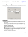
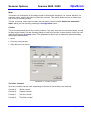
5.3
Parameter Configuration
The parameter dialog shows four tabs to set the Patchcode search options, the counter options, and
the endorser output. Below the pages there is a preview area to give the user an idea of the
endorser’s printout.
Placed on the right side of the dialog are buttons to save and reload the setting for this mode, and a
button labeled "Rules" that opens the "Control Configuration" dialog described later in this text (see
Chapter 5.5 on page 38).
Page 22 of 42
Scanner Options
Scamax 2600 / 5000
DpuScan
Illustration 7 – Patchcodes
As with the other dialogs, the buttons along the bottom work in the same well-known manner:
OK
Closes the dialog box and saves your entries.
Cancel
Closes the dialog without saving your entries.
Apply
Saves your entries without closing the dialog.
Help
Opens the help screen.
The buttons on the right lead to further dialogs, which will be discussed later:
Rules…
Opens a dialog to define events and resulting actions.
Save…
Opens a dialog to save the current mode.
Load…
Opens a dialog to load stored modes.
The following several paragraphs describe the pages for the search and count options as related to
the endorser output configuration.
Page 23 of 42
DpuScan
5.3.1
Scamax 2600 / 5000
Scanner Options
Patchcodes
With the "Patchcodes" tab several settings can be adjusted concerning the search for Patchcodes.
The search can be restricted to the front or rear side of a document, or to a specific search area on
the page. In addition, the quality level can be adjusted to look for thinner or thicker Patchcodes, or to
report an error if a code could not be identified exactly.
Search Patchcodes on Enabling this option turns on the search separately for the front and rear
side.
front / rear side
If you disable the search, Patchcode dependent rules will not be
available.
Interference Reduction This filter reduces white pixels from the black area of a Patchcode bar.
Noise like this can result from the scanner itself after retreatment of an
image by the IP hardware.
Detect thicker / thinner Patchcodes are defined with fixed sizes. To detect Patchcodes varying
the slightest bit from this size, one can choose this checkbox.
Patchcodes
Stop on Error
With this option enabled, the scanner stops when a Patchcode cannot be
identified exactly.
Position and Size of
the Search Area
If the Patchcode bar is not printed over the whole page, but only in a
specific area, a search area can be defined.
With the means of these parameters, the location and the size of the
search area can be defined.
The values are given in 0.1 mm increments.
Please note that the upper border of the search area cannot be specified
because the upper border is always the top of the sheet.
As a general rule of thumb, the Patchcode should be recognized as
soon as possible; that means it should be printed at the upper edge
of a sheet (in direction of transport).
Page 24 of 42
Scanner Options
5.3.2
Scamax 2600 / 5000
DpuScan
How to Set and to Trigger Counters
Illustration 8 – Counter Modes
Field Width
This define how many digits the counter should have. If it is set to, for
example, 3 digits, the counter will count from 0 to 999. After that it resets
to 0 again.
Be aware that the reset and trigger value must be "in range”. In this
example, use a value before counter 1000, because 1000 will never
be reached.
We recommend the use of higher numbered digits for a lower level, and a
lower number of digits for a higher level. For example, if there are many
pages in just a few chapters, 6 digits should be chosen for the Page
Counter, and 2 digits for the Chapter Counter.
If a counter – including the automatic Page Counter A - has a field
width of zero, this counter will not be incremented and interpreted.
The Sequential ID will be incremented always as expected.
Increment Value (by a
certain value)
As a reaction to an event, the corresponding counter will be incremented
by the entered value. For example, the chapter counter can be
incremented while the page counter is at reset value.
Page 25 of 42
DpuScan
Scamax 2600 / 5000
Scanner Options
Page Counter A will always be incremented by 1. Only if Counter A
was reset as the result of an event (Patchcode found, for example)
will the counter be incremented for the next image by a user-defined
value. Afterwards, the counter will be incremented by 1 again.
Reset Value (reset the
counter to a certain
value)
As a result of an event, the corresponding counter will be reset to the
entered value. For example, the page counter can be reset to 0 when a
new chapter begins. The reset value must be in a valid range, and it must
be within the defined field width, as seen in the notes above.
Trigger Value (to cause This defines which count causes an event. For example, the scan job can
an event)
be stopped after 200 pages.
The trigger value must also be in the valid range, as seen in the preceding
notes.
Page 26 of 42
Scanner Options
5.3.3
Scamax 2600 / 5000
DpuScan
How to Print Counters
Here, you configure the format to print counts of the counters on a document after being scanned.
Illustration 9 – Print Counter
It is required that the user selects a field width unequal to 0 on the Counter Modes tab. In the
Illustration above (Counter D), the Roll Number has a field width of 0, and thus it is not in use.
Print Format
Each counter with a field width unequal to 0 can be used to be printed on
the page that was just scanned. If the field width is 0, the counter will be
disabled.
Within the selected field width, the print can be aligned to the left or right,
padded with zero, or unformatted.
You can choose different formats, but the entire length of all counters and
delimiters to be printed are limited for technical reasons.
The result of the chosen format can be seen as a preview ("Numeric
Fields").
The order of the counter is predefined and fixed.
Page 27 of 42
DpuScan
Scamax 2600 / 5000
Scanner Options
If you want this order changed, you will have to configure the counters by
means of levels in events and actions. You can, for example, define that
Counter C will be incremented in level zero and Counter B will be
incremented in level one (new chapter). In this case, Counter C is the
page counter and Counter B is the chapter counter.
Set Counter Delimiter
Delimiters are defined to separate the counters for printing. This means
that it is possible to separate page, chapter, and volume counters in a
different way. In front of the first, and after the last counter, you can enter
one character, and between two counters you can enter up to three
characters.
In the following example, the volume counter with two digits, the chapter
counter with three digits, and the page counter with four digits are
separated by different types of brackets and slashes:
[00]-(000)/<0000>
Page 28 of 42
Scanner Options
5.3.4
Scamax 2600 / 5000
DpuScan
Level and Mode Output – "Print Flags" Tab
The fourth tab allows the user to select how the Sequential ID, the level, the mode, and the flags
should be printed.
Illustration 10 – Print Flags
Sequential ID
The Sequential ID (running number) can be printed with 8 digits, aligned
to the left or to the right, with leading zeros, or of variable length.
Level /
Mode
Mode and Level can be printed with 2 digits aligned, aligned to the left or
to the right, with leading zeros, or of variable length.
Momentary Flag /
Latched Flag
The Momentary and the Latched Flag can be printed this way:
If they are set – as "1", or as "M" or "L"
If they are not set – as "0", as a blank, or just left out ("not in use”).
Page 29 of 42
DpuScan
Fixed Text
Scamax 2600 / 5000
Scanner Options
In addition to numeric values such as counters or flags, the endorser can
print text.
Only the printout text is limited to the number of characters selected here.
The text itself has to be entered in the field "Fixed Text Field", as seen
below. It can hold up to 15 characters.
It makes sense to enter a long, fixed text a lot of information and
send it along with the header to the scan application. On the other
hand, it may be applicable to print out only a small part of the text on
the original document to keep as close to its "original" state as
possible.
Delimiter
5.3.5
You can choose a delimiter to separate Sequential ID, level, mode, and
flags. This character will be printed after a parameter, on the condition
that in at least one of the boxes "Don't print" is not selected.
Preview of Endorser and Header
At the bottom of the Parameter Configuration dialog is a frame titled Endorsement Preview. It
contains an input field for the fixed endorser text, a grayed field for the summary of all counters and
flags output, and some lines that show how many characters are left for the several output fields.
Fixed Text Field
In addition to numeric values such as counters or flags, the endorser can
print text. The text is limited to 15 characters.
The first 10 characters from this string comprise the first (leftmost) part of
Image Address.
Numeric Fields
This field gives an idea of the printout; numbers with leading zeros are
shown as a sequence of zeros ("000"). Numbers with a fixed length are
shown as number/pound signs ("###").
The flags are displayed as their character, where ”L" means latched and
"M" stands for momentary.
If a number has variable length or a flag may be omitted (if unset), the
placeholder is a question mark ("?").
For a SCAMAX the Counter A and the rightmost delimiter are
handled differently by the driver than the other counters, flags, and
delimiters. They do not account for the calculation of the maximum
field length.
The overall length for endorser text is limited by several machine
dependent parameters. For example, with a SCAMAX scanner, the fixed
text field and numeric fields are limited to 15 characters each (except
Counter A and its delimiter, as seen above).
Page 30 of 42
Scanner Options
Scamax 2600 / 5000
DpuScan
When using the %%I fieldcode and a longer lead or trail text in the
endorser setup, the printout may be cut at the end. Hence, it is
recommended that the user test the printout on any document
before starting a "real” scan job.
Below the preview areas for the fixed text field and numeric fields there is a display showing how
many characters are left for each field.
The symbol
indicates that enough space is available to print the complete text.
when the length of the print may vary. The part where length cannot be
It will change to
calculated is then represented by a question mark.
The symbol changes to
as soon as the valid number of characters is surpassed.
To enable a printout, the endorser must first be enabled:
Class Configuration | Data Source | Scanner | Options
At the bottom of the Options page the user will find the edit field String. Here the code %%I must be
entered. This causes the printout of the full endorser text – first the fixed field and then the numeric
fields.
Illustration 11 – Enabling the Endorser
Page 31 of 42
DpuScan
Scamax 2600 / 5000
Scanner Options
Note: Using the normal endorser counter %U when the Patchcode Controlled Index is also in use is
not recommended. This is because the endorser counter uses the same resources as Counter A.
The buttons to load and to save the settings and the button for the rules are located on the right side
of the Parameter Configuration dialog.
5.3.6
Save and Load Modes
All settings for search, count, and output, as well as all rules can be summarized as one mode and
can be stored as a JuK Mode Definition ("*.JMD" file). There is no limit in defining and storing different
modes, nor is there a restriction for definition and saving different modes. A certain number of such
configurations, 15 with an Admis S31 scanner, can be stored directly in the scanner itself, as seen in
Illustration 3 – Inotec Options: Index on Page 12.
The current mode can be stored as a *.JMD file and can later be reloaded as the current mode, using
the Save and Load buttons.
Illustration 12 – Load and Save JMD-Files
It is useful to define modes for recurrent tasks or documents, to store them on a network drive, and to
load the required one to their respective workstations.
Pressing the button Rules, as seen in Illustration 10 on page 29, opens up the dialog for the Index
control of the currently selected mode.
Page 32 of 42
Scanner Options
5.4
Scamax 2600 / 5000
DpuScan
Events and Actions
Use this dialog to set the actions that will happen with which event. The following example defines
that when a Patch II is found, the Chapter Counter is incremented and the Page Counter is reset. In
other words, a new chapter has started within the batch.
Illustration 13 – NDX Rules Patch II
The title line of the dialog displays to which mode the rules relate. On the left side, there is a list of
events that may happen. The box below gives a short description of the selected event; if an event
cannot happen, the reason is displayed here. If, for example, the Patchcode search is not enabled,
Patchcodes cannot be found.
The boxes at the start of each line can be checked only if at least one action is set. The user can
utilize them to make a rule void (e.g. for only the next job) without the need to completely set it again
at a later time.
Use the Reset button to reset all actions for the highlighted line, or for all events.
Page 33 of 42
DpuScan
Scamax 2600 / 5000
Scanner Options
Illustration 14 – Reset Values?
5.4.1
Events
There are several groups of events:
Patchcode Events
These events happen when a certain Patchcode is recognized. Because the search is stopped
after the first Patchcode found, only one such event can happen on any one page.
Level Events:
These events happen when a certain Level is set. Because only one Level can be valid, there
will be one event at max. Therefore, you can decide whether a page in a contract belongs
either to the contract itself, or to its addenda, for example.
Counter Events
Such an event happens when one of the counters reaches its trigger value. Because several
counters may reach their trigger value on the same page, several such events can happen at
one time as well.
Page 34 of 42
Scanner Options
5.4.2
Scamax 2600 / 5000
DpuScan
Actions
There are three groups of Actions:
Actions that set counters
These can reset and then increment the counters. This may influence the counter-based
events or the increment of the automatic counter.
Actions that set flags and level
These can change the flags, the mode, or the level. Changing the level disables checking for
level-based events for the actual sheet, where changing the mode or the flags does not affect
the further process.
Actions on the device control
These can drop the sheet, stop the scanner, or turn the endorser on and off.
5.4.3
Course of Events and Actions
Rules define what actions shall be taken when a special event appears. Checking for the events and
the execution of the resulting actions follows this procedure:
Step 0
Assume that the scanner has scanned a sheet and has done the Patchcode
search. Both images (front and rear) and their headers are ready and waiting to
be sent to the application.
Note: The headers for the current images will not be changed. All
calculations and settings affect only the next sheet.
Step 1
Patchcode-based
events
First of all the software checks if there was a Patchcode on the just incoming
sheet.
If Patchcode search is disabled this step will be skipped.
If there was a code found on the sheet the search for further Patchcodes stops.
So only one Patchcode is found on a sheet in a time.
If no Patchcode was found, the checking of the level (step 3) follows.
When a Patchcode-based rule becomes true the resulting actions take effect:
Page 35 of 42
DpuScan
Step 2
Patchcode-Based
Actions
Scamax 2600 / 5000
Scanner Options
If the field width is equal to a value of anything but 0, the Counters A, B, C,
and D will be reset and then incremented by the specified values. For details,
see Chapter 5.2.3 Counters on Page 19.
Then, the flags, the level, or the mode will be changed.
When the rule changes, the Counter A or the level will be denoted.
If the No Count action is wanted, this will be denoted as well.
In addition, all the hardware related actions such as Drop Page, Stop
Scanner, and Endorser On/Off will not take effect immediately. They will be
retained until Step 7.
Step 3
Now the current level will be checked.
Level-Based Events
This check will be done only if the level was not changed by a Patchcodebased rule before, as seen in Step 2 above. Otherwise, the procedure goes on
with Step 5, which is the incrementing of the automatic counters.
Only one level can be active at a time, so only one of the four levels can cause
resulting actions.
When a level-based rule becomes true the resulting action will be done:
Step 4
This is the same as Step 2.
Level-Based Actions
Step 5
Increment the
Automatic Counters
If the No Count option was enabled in Step 2 or Step 4, this step will be
skipped.
If not, the Sequential ID will now be incremented by 1.
If Counter A was not changed before, it will be incremented by 1 as well.
It doesn’t make sense to enable the No Count option after this step (i.e. in
the "Counter-based” rules).
Step 6
Counter-Based
Events und Actions
Page 36 of 42
The counters will now be checked to reach their trigger values. They will be
checked in the order A, B, C, and then D.
After each check the resulting actions (except the hardware actions, as seen in
Steps 2 and 4) will be performed immediately.
Scanner Options
Step 7
Hardware Control
Scamax 2600 / 5000
DpuScan
After performing the counter and flag handling, the summary of the hardware
actions take effect.
Unless Drop Page is enabled, the page and the last header will be sent to the
host.
If necessary, the scanner stops now.
Otherwise, the endorser will be turned on or off for the following sheet.
Now the counters, flags, and other parts of the header will be updated.
The newly calculated counters are set for the next image, and not for the
current image.
Then, the next scan command including the print command for the endorser is
sent to the machine.
When the machine returns an image, the driver searches for Patchcodes and
merges the result and the further image-dependent values into the header.
Then the procedure restarts at Step 1.
The dialog on the next page is intended to define the rules.
Page 37 of 42
DpuScan
5.5
Scamax 2600 / 5000
Scanner Options
Defining the Rule
When defining a rule, the user must first determine the event and then which action shall result when
the event happens.
5.5.1
Counter Handling
Illustration 14 – Reset Values? on Page 34 shows the tab for counter handling. Depending on an
event, the four counters can be Reset to their initial start value.
After being Reset, the counters will be incremented by a specified value, as seen in Chapter 5.3.2
How to Set and to Trigger Counters on Page 25.
Example 1:
If you want to start page counting after a chapter break with 2 (in order to, for example, insert a large
formatted leading page at a later time) you can specify that Counter A is reset to zero and then
incremented starting from two.
Example 2:
If you want to use only even numbers for page counting only, you cannot use Counter A because it is
incremented automatically by 1 from the second page on. Therefore, you must disable Counter A (set
its field width to zero) and use another counter for these pages (such as Counter B). Each time a level
0 (normal page) document was scanned, Counter B will be incremented by 2.
Page 38 of 42
Scanner Options
5.5.2
Scamax 2600 / 5000
DpuScan
Setting Flags And Level
Illustration 15 – Setting Flags and Level
Set momentary Flag
Check this box to set the momentary flag in the header at Byte 155. The
Patchcode Controlled Index does not verify this flag, but the scan
application can use it to do something exactly for this one sheet, such as
call a function or start a new chapter.
The momentary flag will be reset automatically for the next sheet.
Set / Reset latched
Flag
This sets the permanent flag in the header at Byte 157. Once the latched
flag is set, it remains set until it is reset by another rule or at the beginning
of a new scan job.
Just as with the momentary flag, the Patchcode Controlled Index does not
evaluate the permanent flag, but the scan application can use it to, for
example, mark the addendum pages of a tax form.
Because the flag setting is not evaluated, it can be done immediately after
verifying a rule. That means that the latched flag can be set by a rule and
can be reset later by another rule on the same sheet.
Page 39 of 42
DpuScan
Set Level for the next
document
Scamax 2600 / 5000
Scanner Options
Setting the level causes all rules dependent on the level to be ignored for
this sheet.
Therefore, the new level takes effect for next sheet.
Set Mode (Output
only)
Setting the mode number works only for the printout or the header.
It does not really select a new mode with new parameters and rules.
The mode can be changed only in the corresponding setup dialog of the
scanner, as seen in Illustration 5 – Scanner Properties with Links to the
Patchcode Controlled Index on page 15.
Page 40 of 42
Scanner Options
5.5.3
Scamax 2600 / 5000
DpuScan
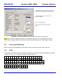
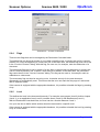
Device Control
Illustration 16 – Device Control
Stop Scanning
This stops the scanner before the next sheet. The current sheet will be
sent to the application unless it is not dropped.
Discard the Sheet
(front and rear side)
If enabled, the document (front and rear side) will not be sent to the host.
Do not increment the
automatic counters
This suppresses the automatic counting in Step 5 of the procedure as
seen in the previous chapter.
Endorser on /
Endorser off
This enables or disables the endorser from the next sheet on, and the
current sheet is not affected.
If different rules enable and disable the endorser, the latter rule takes
precedent.
Page 41 of 42
DpuScan
Scamax 2600 / 5000
Scanner Options
uture
he ffuture
apture tthe
e ccapture
W
We
J&K Imaging, L.P.
1633 Sands Place
Marietta, GA 30067
USA
Phone: (770) 984-1212
Fax:
(770) 953-8399
http://www.JKimaging.com
J&K Imaging South East Asia
76 Wanaping Road
Kenwick WA 6107
Australia
Phone:
+61 (0)8 9493 1591
Fax:
+61 (0)8 9493 2765
http://www.JKimaging.com
Janich & Klass Computertechnik GmbH
Zum Alten Zollhaus 20
D-42281 Wuppertal / Germany
Phone: +49 (0)202 2708-0
Fax:
+49 (0)202 700 625
http://www.janichklass.com/
408.89260.001 9
Page 42 of 42