1
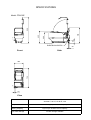
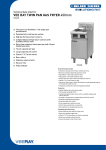
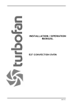
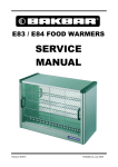
FF8130E / FF8135E / FF8140E FRYER FILTER
Installation / Operation Manual
-1-
MANUFACTURED BY
Moffat Limited
P O Box 10-001
Christchurch
New Zealand
Ph:
(03) 3891-007
Fax:
(03) 3891-276
WORLD-WIDE BRANCHES
UNITED KINGDOM
Blue Seal
Units 6-7, Mount Street Business Park
Mount Street, Nechells
Birmingham B7 5 QU
Ph:
(121) 327-5575
Fax:
(121) 327-9711
UNITED STATES
Moffat Inc
3765 Champion Blvd
Winston-Salem
North Carolina 27115
Ph:
(336) 661 0257
Fax:
(336) 661 9546
CANADA
Lessard Agencies Ltd
P O Box 97
Stn D Toronto
Ontario M6P3J5
Ph:
(416) 766-2764
Fax:
(416) 760-0394
NEW ZEALAND
Christchurch
Moffat Limited
P O Box 10-001
16 Osborne Street
Christchurch
Ph:
(03) 3891-007
Fax:
(03) 3891-276
Auckland
Moffat Limited
4 Waipuna Road
Mt Wellington
Auckland
Ph:
(09) 574-3150
Fax:
(09) 574-3159
AUSTRALIA
Victoria
Moffat Pty Limited
740 Springvale Road
Mulgrave, Melbourne
Victoria 3171
Ph:
(03) 9518-3888
Fax:
(03) 9518-3838
New South Wales
Moffat Pty Limited
8/142 James Ruse Drive, Rose Hill
P O Box 913, Smithfield
Sydney, N.S.W. 2142
Ph:
(02) 8833 4111
Fax:
(02) 8833 4133
Western Australia
Moffat Pty Limited
P O Box 689
Joondalup Business Centre
WA 6027
Ph:
(09) 305-8855
Fax:
(09) 308-8838
Queensland
Moffat Pty Limited
30 Prosperity Place
Geebung, Brisbane
Queensland 4034
Ph:
(07) 3215-9155
Fax
(07) 3215-9170
South Australia
Moffat Pty Limited
28 Greenhill Road
Wayville
South Australia 5034
Ph:
(08) 8274 2116
Fax:
(08) 8274 2129
-2-
Filtamax Fryer Filter
Contents
Page
Introduction ........................................................................................................ 5
Specifications ..................................................................................................... 6
Installation .......................................................................................................... 9
Before Checking Operation
Electrical Supply
Installation / Storage
Operation .......................................................................................................... 10
Preparation of Fryer
Preparation of Filter Unit
Important points to remember
Carbon Filter Pads - option ............................................................................. 13
Cleaning ............................................................................................................ 15
Trouble Shooting ............................................................................................. 16
Wiring Diagram................................................................................................. 17
Spare Parts ....................................................................................................... 19
Date Purchased............................................ Serial No...................................................
Dealer..............................................................................................................................
Service Agent...................................................................................................................
F25896-1
-3-
-4-
INTRODUCTION
Filtering oil is essential to maintain consistent high food quality, extend oil life, prevent smoking and
saving on costs.
"Filtamax" complements your Sterlec or Waldorf Single and Twin pan fryers, providing a truly affordable
filtration system with unique space saving and mobility features.
Storage
"Filtamax" is housed conveniently below your Fast Fri fryer (30/40 models), utilising the otherwise
wasted space, refer specifications, pages 6-8.
Mobility
"Filtamax" can be easily wheeled from its housing to filter any other fryers of the same tank capacity,
refer specifications, pages 6-8.
Safety
The rigid delivery tube has a heavy duty insulated handle and positions firmly into position, safe from
spillage. There are no flexible hoses and no coupling disconnection’s required.
Economy
The reusable filter bags, suitable for up to 500 filters can be easily cleaned and simply drop back into
place.
Carbon Pad Option
Upgradeable to carbon pad filtering. Refer to your Filtamax dealer for details.
Speedy operation
The whole operation takes approximately 10 minutes to drain, filter and refill a typical fryer tank.
WARNING
•
•
•
•
ALWAYS TURN FRYER OFF BEFORE USING FILTER MACHINE
DO NOT USE FILTER MACHINE AS AN OIL STORAGE VESSEL
NEVER STORE FILTER MACHINE UNDER FRYER WITH OIL IN FILTER
MACHINE
ALWAYS USE PROTECTIVE GEAR WHEN FILTERING HOT OIL
-5-
SPECIFICATIONS
562
1
E
112
E
339
1
391
956
Model: FF8130E
ELECTRICAL ENTRY
Front
Side
683
324
1
E
34
Plan
Electrical Connection
110/120V, 60Hz, 1P+N+E, 6.4A
220/240 V, 50 Hz, 1P+N+E, 3.2A
Pump
1/3 HP single phase reversible pump
Filtering Capacity
Fryers up to 20 litres cold oil capacity
Fryer Filter Storage
Waldorf FN8120G / FN8226G
-6-
24
SPECIFICATIONS
562
1
E
112
E
390
1
450
956
Model: FF8135E
ELECTRICAL ENTRY
Front
Side
735
324
1
E
34
Plan
Electrical Connection
110/120V, 60Hz, 1P+N+E, 6.4A
220/240 V, 50 Hz, 1P+N+E, 3.2A
Pump
1/3 HP single phase reversible pump
Filtering Capacity
Fryers up to 30 litres cold oil capacity
Fryer Filter Storage
No filter storage available
-7-
24
SPECIFICATIONS
561
1
E
124
E
344
1
395
957
Model: FF8140E
ELECTRICAL ENTRY
Front
Side
683
474
1
E
34
Plan
Electrical Connection
110/120V, 60Hz, 1P+N+E, 6.4A
220/240 V, 50 Hz, 1P+N+E, 3.2A
Pump
1/3 HP single phase reversible pump
Filtering Capacity
Fryers up to 32 litres cold oil capacity
Fryer Filter Storage
Waldorf FN8130GHPO
-8-
24
INSTALLATION
It is most important that the filter is checked and that the unit is operating correctly before handing over
to the user.
Before Checking Operation
Unpack and check unit for damage and report any damage to the carrier and supplier. Report any
deficiencies to your supplier.
Check that the unit has been supplied with the following:
1 x Filter Bag
1 x Filter Bag Frame
1 x Return Delivery Tube
Electrical supply
Check that the available power supply is suitable. The filter rating plate is located on the side panel
below the return delivery tube swivel fitting.
110-120V, 60Hz, 1P+N+E, 6.4 Amp
220-240V, 50Hz, 1P+N+E, 3.2 Amp.
The Filter unit is a mobile appliance and is provided with a 2.5 metre cord set for plugging into a
matching electrical socket of the required electrical supply when in use.
When not in use the cord set is stored around the cord-stowage frame on the filter unit’s handle.
Important: If an electrical socket is not located in range of the filter cord set when the filter is in position,
an extension cord will be necessary. Only use an extension cord with suitable residual current device
(R.C.D) circuit breaker. Ensure the R.C.D is connected between the power supply and the
extension cord.
Installation / Storage
FF8130E
The FF8130E Fryer Filter is designed for use with Waldorf FN8120G and FN8226G gas
fryers. The filter is easily stored under these fryers, it can however be stored anywhere
provided it is not obstructing normal kitchen traffic and obstructing use of other equipment.
FF8135E
The FF8135E Fryer Filter is designed for use with Sterlec FN8123E/EE, FN8226E,
FN3050ECS and FN3052ECS electric fryers. As it cannot be stored under the fryers, it can
be stored anywhere provided it is not obstructing normal kitchen traffic and obstructing use
of other equipment.
FF8140E
The FF8140E Fryer Filter is designed for use with Waldorf FN8130GHPO gas fryers. The
filter is easily stored under these fryers, it can however be stored anywhere provided it is not
obstructing normal kitchen traffic and obstructing use of other equipment.
Never store the fryer filter in a location where it may be subject to damage or foreign matter being
dropped into the filter tank or filter bag.
-9-
OPERATION
WARNING
•
•
•
•
ALWAYS TURN FRYER OFF BEFORE USING FILTER MACHINE
DO NOT USE FILTER MACHINE AS AN OIL STORAGE VESSEL
NEVER STORE FILTER MACHINE UNDER FRYER WITH OIL IN FILTER
MACHINE
ALWAYS USE PROTECTIVE GEAR WHEN FILTERING HOT OIL
Preparation of Fryer
1.
For safe working practice the fryer should only be filtered with the oil temperature between
120° - 150°C.
2.
Always ensure the fryer is turned off when filtering.
3.
Cold oil or solid shortening will not filter effectively, therefore if filtering from a cold start set
thermostat to 150°C, ie. maximum filtering temperature and allow oil to come up to temperature
before starting filter process.
Preparation of Filter Unit
1.
With oil in fryer tank at filtering temperature, ensure fryer is turned off.
2.
Open fryer door.
3.
If filter unit is stored under fryer to be filtered, pull filter unit out from under fryer.
4.
Ensure filter bag is fitted correctly, refer figure A.
Label at handle
end of frame
Place cord attached to bottom of
bag around handle to assist with
emptying of bag.
1.
2.
Ensure all domes are fastened
around frame.
Figure A.
5.
Lift up return tube assembly and position filter bag frame in front mounting holes (holes nearest
return tube) so that filter bag is in the correct filtering position (horizontal).
-10-
OPERATION
6.
Unwind electrical supply cord of Filtamax filter from around cord hanger and plug into correct
electrical supply. Ensure filter control switch is in the “Off“ position before turning electrical supply
on.
7.
Switch on electrical supply.
8.
Push Filtamax filter unit back into cabinet so that the filter bag drain guard is positioned over the
drain valve of the fryer.
9.
Position the return tube over the nose rail of the fryer so that the outlet is positioned towards the
inside of the fryer tank.
10.
The fryer is now ready for filtering.
11.
Release the safety catch on the fryer drain valve and slowly open the valve. Drain entire contents
of fryer tank into the filter unit.
12.
When contents of fryer have been drained into filter unit, remove the sediment tray from the fryer
tank for separate cleaning.
13.
Holding the return tube insulated handle with one hand, set the filter pump switch to the forward
position. The filter will now start pumping the oil from the filter tank back into the fryer tank.
14.
With the drain valve still open the returning oil can now be used to wash down sediment from
around the tank sides out the drain and into the filter bag.
To get at all the sediment on the tank insides it may be necessary to use a scrubbing brush to
assist with the oil washing down.
15.
When the inside of the fryer tank has been suitably washed out, set the filter pump switch back to
the “off” position and close the fryer drain valve.
16.
The filtered oil can now be returned back to the fryer tank. With the drain valve still closed, set the
filter pump switch to the “forward” position again and pump the oil back into the fryer tank.
17.
When oil ceases to exit from the return tube and the pump appears to be pumping air only, set the
filter pump switch back to the “off” position.
18.
Lifting away the return tube by the insulated handle carefully pull the filter unit out from under the
fryer until the filter unit is clear.
19.
Remove the filter bag and frame from the filter unit.
20.
Place the return tube back into it’s storage position.
21.
The filter bag sediment contents should now be discarded. The filter bag itself once emptied of
the sediment should be cleaned by washing out in hot water only. It is not necessary to unclip the
filter bag from the filter bag frame for washing out purposes, although this may be done if desired.
22.
With the return tube back in it’s storage position, set the filter pump switch to the “reverse” setting
to flush out any oil contained in the pump system back into the filter tank.
NOTE:
It is necessary to hold the filter pump switch when in the reverse position for approximately
5-10 seconds to effectively flush all the oil from the pump system.
IMPORTANT
Always ensure that the reversing pump flush out procedure is carried out at the
end of a filter operation. If this procedure is not followed, oil or shortening may
solidify in the pump system and cause blockages when next filtering.
-11-
OPERATION
23.
The residual oil now left in the base of the filter tank should now be mopped out and the filter tank
cleaned out dry. Do not use a soapy solution to wash out the filter tank as soap is alkaline based
and it is alkali’s that are responsible for rapid oil breakdown.
24.
Place the filter bag and filter bag frame back into the filter unit by positioning the legs of the filter
bag frame into the rear positioning holes in the top of the filter tank so that the filter bag frame
rests down on an angle and the filter bag frame handle sits flat on top of the pump housing.
25.
Switch off the electrical supply and disconnect the filter supply cord. Wind the supply cord back
around the filter handle and cord hanger in a clockwise direction tidily.
26.
The filtering process is now complete and the filter can be pushed back under the fryer for
stowage.
Important Points to Remember When Filtering
a)
Always ensure the oil temperature is safe for the filtering process.
Ideally it should be between 120° - 150°C.
b)
Always ensure the reverse flushing operation for the pump system is conducted to eliminate the
possibility of blockages occurring in the pump system particularly when using shortening.
NOTE:
If this procedure is not conducted or if the residual shortening left in the base of the filter tank
at the end of a filter operation is not mopped out and the shortening has been left to solidify,
it will be necessary to either:i)
Remove the solid shortening from the base of the filter tank (ensure bleed hole in pick
up tube is also free of shortening, refer figure B.) before starting the next filter
operation.
ii)
When next filtering leave the hot oil or shortening in the filter tank for 10-15 minutes to
allow the hot oil to melt any solid shortening left in the base of the filter tank or in the
pump pick up tube inside the filter tank.
Pick up tube bleed hole.
Figure B.
c)
The filtering process is designed to be conducted with the operator always in attendance. Do not
leave the filter unit pumping oil unattended.
d)
Under heavy use situations, the sediment etc accumulated in the cool zone of the fryer may
require the filtering process to be conducted twice.
e)
Due to the temperature of the oil being pumped, filtering should always be done with due caution
being taken. Never touch the return delivery tube except for the insulated handle.
-12-
CARBON FILTER PADS - OPTION
Filter Pad - Option
With Supersorb Carbon pads you can achieve even better quality by removing particles 30-50 times
smaller than can be removed with standard filtering methods. Which means food can be cooked more
efficiently, it tastes better, and you will benefit from reduced oil replacement costs.
If it is desired to use carbon filter pads, then the Filter Pad Kit (part 025669) is required.
To purchase carbon filter pads contact your Filtamax dealer, pad type - FILCO SUPER SORB F16
Converting to Pad Filtering
Strainer Frame
1)
Remove filter bag from bag frame.
2)
Insert strainer into frame (refer figure A).
3.
1.
2.
Figure A.
Fitting Filter Pad to Filter
1)
Ensure inside of filter is clean (refer Cleaning Instructions page 15).
2)
Place Filter Plate in bottom of filter (refer figure B).
3)
Fit filter pad with the rough surface up (refer figure C).
NOTE: The pad has one corner removed which must line up with the corner bracket in the
front of the tank.
Corner Removed
Filter Plate
Filter Pad
Figure B.
Figure C.
-13-
CARBON FILTER PADS - OPTION
4)
Fit filter clamp over filter and lock into place by rotating handle (refer figure D).
5)
Place strainer frame on filter unit (refer figure E), Filter is ready for use.
Filter Clamp
Frame in filtering position
Figure D.
Figure E.
Filter Pad Replacement
Filter pads should be replaced daily to maintain filtering efficiency and to ensure good hygiene.
Filter unit must be empty. If the unit has recently been used for filtering, allow sufficient time for items
inside the tank to cool to a safe handling temperature before proceeding.
1)
Remove strainer and place the return tube assembly to the storage position (refer figure F).
2)
Release filter clamp by rotating latch handle a ¼ turn in either direction (refer figure D). Pivot
clamp to upright position. (Remove if cleaning required).
3)
Remove old filter pad. Remove any crumbs or residue from inside of tank by wiping clean
(refer figure G).
4)
If required, the filter plate can also be removed, cleaned, and refitted (refer figure B).
5)
Fit new filter pad with rough surface up.
NOTE:
6)
The pad has one corner removed which must line up with the corner bracket in the
front of the tank (refer figure C).
Refit filter clamp and secure latch (handle facing rear of tank, refer figure D). Refit strainer.
Filter unit is now ready to be used.
Figure F.
Figure G.
-14-
CLEANING INSTRUCTIONS
Exterior
Clean with detergent. You may require to use a good quality stainless steel cleaner or stainless
steel wool for heavy duty cleaning. Always apply cleaner when the filter is cool and rub in the
direction of the “grain”.
Do not use detergent or stainless steel cleaner on inside of filter tank.
Interior
Refer to the operating instructions for filter tank cleaning necessary after each filter.
For general cleaning, the interior of the filter tank should be cleaned out with dry rags or kitchen
towels.
As filtered oil comes into contact with the inside surfaces of the tank it is important that cleaning will
not leave moisture or more importantly detergent residues on the tank surface as these will
breakdown the oil when they come in contact.
Therefore:DO NOT - run a water/detergent solution through the filter system.
DO NOT - run hot water through the filter system.
If it is necessary to thoroughly clean the inside of the filter tank, a hot wash can be carried out. This
should be performed by tipping the fryer filter on its end (so the filter handle is up) and manually
wash out the filter tank with a scrubbing brush or similar.
ALWAYS dry tank with dry rags or kitchen towels before filtering oil or shortening.
Filter Pad - Option
Remove mesh strainer and clean in hot water only, dry.
Remove filter pad (refer filter pad replacement, page 14)
Remove filter clamp and clean in hot water only, dry.
Lift out filter plate by wire handle in centre of plate and clean in hot water only, dry.
The residual oil left in the base of the filter tank should now be mopped out and the filter tank
cleaned out dry. Do not use a soapy solution to wash out the filter tank as soap is alkaline based
and it is alkali’s that are responsible for rapid oil breakdown.
Refit filter plate, new filter pad, filter clamp and strainer.
Filter Bags
Refer to Operating Instructions for filter bag cleaning necessary after each filter operation.
NEVER WASH FILTER BAGS OUT IN A DETERGENT SOLUTION.
Only ever wash filter bags in hot clean water.
Always dry out filter bags before filtering oil or shortening.
-15-
TROUBLE SHOOTING
ENSURE POWER IS SWITCHED OFF BEFORE SERVICING.
All servicing should be carrier out by a competent electrical serviceman.
FAULT
Motor/Pump will not operate (no
motor/pump noise).
CAUSE
No power to unit.
REMEDY
Check supply cord connection.
Check power supply is on.
Check power is available at
supply.
Motor overload protection has
tripped.
Motor/Pump will not operate
Motor / Pump stalled.
(motor/pump makes noise but will
not pump oil/shortening).
Blockage in pump or delivery
system.
All other faults refer to an authorised service company.
-16-
Remove access plug from L/H
side panel and reset overload
switch (depress).
Switch off then switch on again
either in forward or reverse
direction.
Refer operating instructions “Important points to remember”
page 12.
If unable to free blockage contact
an authorised service company.
E
3
T5/Z5
4
T8/Z8
5
T4/V4
6
T2/V2
7
8
T3/V3
MOTOR/PUMP
022115
P1/P1
9
10
P2/P2
7 CRIMP CONNECTORS 013114
T3
P2
P1
T2
T4
JUMPERS TO CONNECT
3 TO 7 & 7 TO 11
8
10
9
7
6
P
1
N
-17-
5
4
2
1
T8
T5
N
P
3
E
TERMINAL BLOCK 017369
2
JUMPER TO CONNECT
5 TO 1
2
6
10
SWITCH
019696
1
5
9
12
8
7
11
4
3
WIRING DIAGRAM
110 - 120V, 60Hz, 1P+N+E, 6.4A
E
8
T5/Z5
2
P2/P2
3
T8/Z8
19999
CONNECTOR
T4/V4
4
T2/V2
5
5
T3/V3
MOTOR/PUMP
022115
P1/P1
6
6 CRIMP CONNECTORS 013114
JUMPERS TO CONNECT
3 TO 7 & 7 TO 11
3
2
1
5
P
1
N
-18-
8
E
TERMINAL BLOCK 017369
7
JUMPER TO CONNECT
5 TO 1
SWITCH
019696
2
6
5
7
5
10
1
9
12
8
7
11
4
3
6
4
WIRING DIAGRAM
220 - 240V, 50Hz, 1P+N+E, 3.2A
SPARE PARTS
FF8130E / FF8135E / FF8140E FRYER FILTER
Part No.
Description
025669
Filter Pad Kit - Option
019695
Filter Bag
019784
Filter Bag Frame (FF8130E / FF8135E)
025521
Filter Bag Frame (FF8140E)
023007
Motor/Pump Switch
023009
Motor Switch Seal
019684
Quick Connect Coupling Stem
019683
Quick Connect Coupling Body
020717
Swivel Union Assembly
022814
Oil Pick Up Tube
019808
Motor Overload Access Plug
019668
Filter Handle (FF8130E / FF8135E)
024008
Filter Handle (FF8140E)
022115
Motor/Pump Assembly
025848
Pump
SA1159
Wand Assembly (FF8130E / FF8135E)
SA1556
Wand Assembly (FF8140E)
020417
Flexible Hose Assembly (FF8130E / FF8135E / FF8140E) - Option
O-Ring replacements for the quick-connect coupling body are:SWAGELOCK - Type VITON - Code VT-114-70-OR
or equivalent VITON O-Ring 5/8” x 3/32”
O-Ring replacements for the swivel fitting body are:VITON O-Ring 3/4” x 1/16”
-19-
-20-
-21-
-22-