1
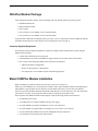
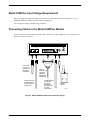
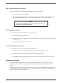
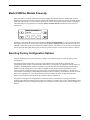
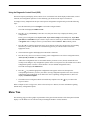
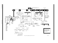
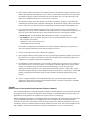
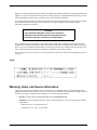
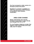
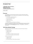
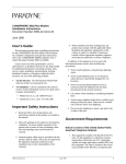
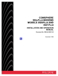
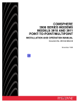
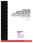
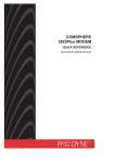
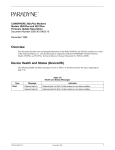
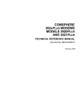
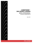
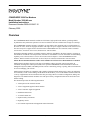
COMSPHERE 3920Plus Modems Model Number 3920-A2-xxx Installation Instructions Document Number 3920-A2-GK47-10 February 2002 Overview The COMSPHERE Model 3920Plus modems are full-feature, high-speed leased modems, providing reliable asynchronous and synchronous operation over leased or dial-line networks with data rates as high as 33,600 bps. The COMSPHERE 3920Plus modem is available in several models. This document refers to model numbers in the 3920-A2 series, which are singleport modems with single-rate power supplies. Modems in the 3920-A1 series have universal power supplies and are described in the COMSPHERE 3900 Series Modems, Models 3920Plus and 3921Plus, Installation Instructions, Document No. 3920-A2-GK41. Through downloading capability, any Model 3920Plus modem is upgradable to the latest firmware, requiring no new hardware investment or on-site personnel, with little or no downtime. For more information on downloading capability, refer to the Automatic Firmware Download section in Chapter 3 of the COMSPHERE 392xPlus Modems, Models 3920Plus and 3921Plus, Technical Reference Manual, Document No. 3920-A2-GH30. NOTE: Do not download firmware with a release number lower than 4.0 to a Model 3920-A2-xxx modem. Model 3920Plus modems support a wide range of modulation schemes and offer control using either AT commands, the diagnostic control panel (DCP) or the optional COMSPHERE 6700 and 6800 Series Network Management Systems (NMS). The NMS performs extensive monitoring, testing, reporting, and restoral functions to assist in managing your network. Model 3920Plus modems are compatible with a number of dialing methods and protocols, such as asynchronous AT commands, CCITT V.25bis dialing, and the DCP. The DCP allows you to use the Model 3920Plus modem in a variety of applications and environments while also providing control over modem configuration, dialing, and diagnostics. The Model 3920Plus modems come with preset factory configurations that are the most often used modem settings. This document provides the following information: • A description of the 3920Plus modem • A list of equipment supplied with the modem • A list of customer supplied equipment • Installation instructions • A 392xPlus Menu tree • Important safety instructions • Regulatory notices • Government requirements and equipment return information 3920-A2-GK47-10 February 2002 1 This document is intended to be used in conjunction with the COMSPHERE 392xPlus Modems, Models 3920Plus and 3921Plus, Technical Reference Manual, Document No. 3920-A2-GH30. This manual is available online at www.paradyne.com. Select Library -> Technical Manuals -> Business Class Analog Modems. Ordering Information Call your sales representative to order additional product documentation or to verify the correct model number for your geographic area. COMSPHERE 3920Plus Modem The Model 3920Plus singleport modem is a standalone modem (Figure 1) capable of either 4-wire/2-wire leased-line or dial operation. This modem is controlled using either AT commands or the DCP. The DCP consists of a liquid crystal display (LCD), three function keys, four directional keys, and a row of 13 LED status indicators. For a better understanding of DCP operation, refer to Chapter 3, DCP Operation, in the Technical Reference Manual. DIAGNOSTIC CONTROL PANEL POWER SUPPLY LCD AND KEYPAD STATUS INDICATORS LEASED DIAL DTE 1 NMS POWER IN POWER ON/OFF 97-14678-02 Figure 1. Model 3920Plus Modem (North America Model) 2 February 2002 3920-A2-GK47-10 392xPlus Modem Package After opening the modem’s package, check for damage and verify that the following items are present: • Installation instructions • Model 3920Plus modem • Power supply • One 6-position, 4-wire modular cord (in selected models) • One 8-position, 8-wire modular cord (in selected models) If any hardware components are damaged, notify your sales or service representative. Return equipment using the procedures described in Government Requirements and Equipment Return on page 11. Customer-Supplied Equipment The following customer-supplied equipment is required to complete a data communications system using the Model 3920Plus modem: • A DTE with available EIA-232-D serial port. • A standard EIA-232-D cable with a DB-25-P (plug) connector at one end to attach to the modem. • One or more of the following modular leased or dial network interfaces: — JM8 for leased-line configurations. — RJ11C for dial permissive configurations. — One 8-position, 8-wire modular cord (for leased backup purposes). Model 3920Plus Modem Installation Before installing your modem, read the Important Safety Instructions on page 10. Make sure your installation site is clean and well-ventilated. Allow space around the modem for installing cables and telephone cords, and make sure the modem is located within reach of the ac power outlet. The distance between your modem and DTE should be minimized if DTE data rates exceed 19,200 bps. Also, low capacitance cables may be necessary for speeds greater than 19,200 bps or distances greater than 50 feet. The back panel of the Model 3920Plus modem (Figure 2) has the following switches and connectors: • An ON/OFF power switch. • A cylindrical power receptacle (PWR) for the dc power supply. • An 8-pin modular keyed jack (LEASED) for 4-wire/2-wire leased lines. • An 8-pin modular keyed jack (DIAL) for backup lines (2-wire dial or 2-wire leased). • A 4-pin modular jack (NMS) for the Network Management System connection. • A 25-pin DB-25-S receptacle for the DTE interface. 3920-A2-GK47-10 February 2002 3 Model 3920Plus Input Voltage Requirements The power supply used with model number 3920-A2-201 is a wall-mount transformer designed for 110 vac. Additional models are available for other voltages and plug types. Use only the power supply included with your modem. Connecting Cables to the Model 3920Plus Modem Figure 2 illustrates the Model 3920Plus modem cable connections. For pin assignments, refer to Appendix C in the Technical Reference Manual. DIAL LEASED 8-POSITION PLUG FOR LEASED-LINE NETWORK OPERATION 6-POSITION PLUG FOR PERMISSIVE DIAL NETWORK OPERATION DTE 1 NMS PWR ON OFF DB-25-P CONNECTOR FOR DATA TERMINAL EQUIPMENT OPERATION SUB-MINIATURE 4-POSITION PLUG FOR NETWORK MANAGEMENT SYSTEM OPERATION POWER SUPPLY 97-14677-01 Figure 2. Model 3920Plus Back Panel and Power Supply 4 February 2002 3920-A2-GK47-10 Data Terminal Equipment Connection Use the following steps to connect an EIA-232-D cable from the modem to a DTE: 1. Make sure the modem is powered OFF. 2. Connect the DB-25-P (plug) connector on the cable to the DB-25-S (socket) connector (Figure 2) on the modem’s back panel, labeled DTE 1. Use a small screwdriver to secure the cable to the modem. NOTE DTE rates above 19.2 bps require cable lengths less than fifty feet as specified by the RS232 standard. Power Supply Connection Use the following steps to connect the modem to an ac power outlet: 1. Make sure the modem is powered OFF. 2. Insert the power supply’s cylindrical connector into the modem’s back panel dc power receptacle, labeled PWR (Figure 2). 3. Connect the power module to an ac power outlet. Leased-Line Network Connection Use the following steps to connect the leased-line network interface: 1. Insert the 8-position, 8-conductor modular plug into the jack labeled LEASED (Figure 2). 2. Insert the other end of the modular cord into the leased-line network interface. 3. If the Model 3920Plus has a backup line, follow the steps listed in the Dial Backup Connection section. Dial Network Connection The telephone company provides the line termination jacks for the permissive service you request. Advance coordination with the telephone company is suggested when connecting the modem to telephone dial lines (PSTN). In the Permissive mode, the modem’s transmit output level is fixed at –9 dBm. The telephone company assumes that the line loss is 3 dB and no compensation is provided for additional losses. A Permissive mode telephone line is usually terminated with a USOC RJ11C jack. 3920-A2-GK47-10 February 2002 5 Leased Backup Connection Use the following steps to connect the modem to the 2-wire leased backup network interface: 1. Insert the 8-position, 8-conductor modular plug into the jack labeled DIAL (Figure 2). 2. Insert the other end of the modular cord into the leased-line network interface. Dial Backup Connection Use the following steps to connect the modem to the dial network interface: 1. Insert the 6-position, 4-conductor modular plug into the jack labeled DIAL (Figure 2). 2. Insert the other end of the modular cord into the dial network interface. Network Management System Connection Use the following steps to connect the modem to the network management system (NMS) interface: 1. Insert the sub-miniature, 4-conductor modular plug of the 3600 Hubbing Device into the jack labeled NMS (Figure 2). Refer to the 3600 Hubbing Device, Feature Number 3600-F3-300, Installation Instructions, Document No. 3610-A2-GZ45, for a description of the 3600 Hubbing Device. Installation for the 3920Plus is the same as for the 3610 DSU. 2. Connect the 3600 Hubbing Device to the network management system (Figure G-5 in Appendix G of the Technical Reference Manual). Removing and Replacing the Model 3920Plus Modem To remove and replace the Model 3920Plus modem, perform the following steps: 1. Make sure the modem is offline. Press the modem’s back panel power switch to OFF. 2. Disconnect the dc power cable from the connector on the back of the modem. 3. Disconnect the leased-line and dial modular cord(s) from the modem’s back panel. 4. Disconnect the DTE interface cable(s) from the modem’s back panel. If the modem is to be removed for service, return it to the company using the procedures described in Government Requirements and Equipment Return on page 11. 5. Install the replacement modem as described in the Model 3920Plus Modem Installation section, and configure it the same way as the modem being replaced. 6 February 2002 3920-A2-GK47-10 Model 3920Plus Modem Power-Up Once your modem is properly connected to the power supply, leased and/or dial lines, and the DTE, press the modem’s back panel power switch to the ON position. The modem begins a power-up self-test, in which all DCP LEDs light. This test takes several seconds to perform, and verifies the operation of most hardware components within the modem. If successful, the LCD displays Power on Selftst Passed and continues to the Top-Level menu screen. Power On Selftst Passed F1 F2 F3 If a failure occurs during the self-test, the LCD displays Power On Selftst Failed for several seconds. The LCD then displays the Top-Level menu screen with the message Power on Fail appearing on the top line of the LCD. Although a failure has occurred, the modem will attempt to operate. This allows you to activate a more thorough self-test using the Test branch. Refer to the Test Branch section in Chapter 3 of the Technical Reference Manual. Selecting Factory Configuration Options After the modem passes the power-up self-test, configure it for operation using one of the six factory preset configurations. The Model 392xPlus modems have six factory preset templates that contain the most commonly used configuration options (straps) for Synchronous Leased (Answer or Originate), Asynchronous Leased (Answer or Originate), Trellis Multipoint (Control or Tributary), Asynchronous Dial, Synchronous Dial, and UNIX Dial hardware network configurations. Your modem is shipped from the factory with the Synchronous Leased (Answer) default configuration options stored in memory. If Synchronous Leased (Originate), Asynchronous Leased (Answer or Originate), Trellis Multipoint (TMp) (Control or Tributary), Async Dial, Sync Dial, or UNIX Dial is more appropriate for your configuration, then you must change the factory setting using either the modem’s DCP (as described in the following sections) or the AT command set. The purpose of having preset configurations is so that you can have a “head start” in getting your modem operating and reducing the amount of time required to configure your modem. For a better understanding of DCP operation and factory preset configuration options, refer to Chapter 4, DCP Configuration, in Technical Reference Manual. 3920-A2-GK47-10 February 2002 7 Using the Diagnostic Control Panel (DCP) The DCP’s liquid crystal display (LCD) consists of two 16-character lines which display modem status, control functions, and configuration options as well as indicating your location in the Top-Level menu tree. To change a factory template from the Sync Leased preset configuration using the DCP, perform the following steps: 1. Press the function key below Configure to select the Configure branch. The LCD now displays Ld EditArea frm. key until Factory comes into view, then press the F1 key to display the factory preset 2. Press the configurations. Factory preset configurations are Sync Leased, Async Leased, TMp (Trellis Multipoint), Async Dial, Sync Dial, and UNIX Dial. If Sync Leased or Async Leased is selected, you must choose either Answer or Originate mode. If TMp is selected, you must choose either Control or Trib (Tributary) mode. 3. Press the key until the appropriate factory preset appears on the LCD, and press the corresponding function key to select your choice. (For certain factory presets you will also need to choose the appropriate mode.) 4. Choose Function appears and displays the Edit and Save functions. 5. Press the F3 key (Save) to save the new factory preset configuration to one of three configuration areas, Active (Saved), Customer 1, or Customer 2. (These three configuration areas are nonvolatile memory locations. Active (Saved) contains the most recently saved changes to any configuration options. In the event of power loss, the modem retrieves these configuration options. Customer 1 and Customer 2 are user-defined configuration areas.) The LCD now displays Sav EditArea to. 6. Press the key until the appropriate configuration area appears on the LCD, then press the corresponding function key to select your choice. (Saving configuration options to the Active (Saved) configuration area automatically saves them to the Active (Operating) configuration area.) The LCD displays Command Complete. 7. The modem is now configured with the selected factory template. Press the Top-Level menu. key to return to the Refer to Chapter 4, DCP Configuration, in the Technical Reference Manual, for more information regarding default factory configuration options. Menu Tree The following page provides a graphic representation of the general menu structure of the front panel or SDCP display. Use the Menu Tree for reference when performing the modem’s various functions. 8 February 2002 3920-A2-GK47-10 3920-A2-GK47-10 Displays current status of modem along with data rate and error control mode. "Status" Status Configure PList Control Ld EditArea frm: Activ (Operating) Display DeviceHS Identity VF February 2002 Major Minor Status Dial Thresh Security Port1 Port2 Port3 Port4 Display Backup SDC Ser# Mod# FRev HPt# FPt# Country Clear SigQual RcvLevel Sig/Noise NrEchLv FarEchLv FarEchDel EchoFreqOff Phase Hts Impul Hts DropOuts Retrains Phas Jtr NonLnear FreqOffset Gain Hts Tx Rx DTE Rate Cmp Ratio Efficiency LSD DTR DSR Tst TXD RXD RTS CTS Line = Pri 4W APL Line = Pri 2W APL Line = Bkup 2W APL Line = Dial Backup Line = Dial ONLY Line = No Sync Change Customer2 Service_Log Dial Security Change_Directory Choose Password (TMp only) Dial_Standby or Return_to_Dial Secondary Self Rem_Digital_Loop Loc_Analog_Loop Pattern Loc_Digital_Loop Set_Access_Ctrl TxRate RxRate SymbolRate TxLevel AsymRate (3921Plus only) Choose Function Reset Speaker Data_Stream Save Edit StrapGroup Make_Busy or RemoveMakeBusy EIA_LEDS Customer1 Active (Saved) (Singleport mode only) DTE_Interface (Singleport mode only) Line_Dialer DTE_Dialer Customer2 Leased_Line Dial_Line V42/MNP/Buffer Reset_Security (Admin Password?) Download_Code (DownloadSoftware) Service_Line or DiscServLine (Singleport mode only) Test Prim (data blckd) (ExitRem appears instead of Remote when using Remote mode) UNIX_Dial Abort Remote Choose Address (TMp Control only) Directory Locations 1 24 Trib Originate Tlk/Data Answer Disconnect Async_Dial Control Answer Acquire Choose Mode Choose Mode Display Clear Add Sync_Dial TMp Async_Leased Record Options V.34 Call_Setup (Dial Backup only) Active Delete Skip Sync_Leased DTE Clear Factory Port Select (Multiport mode) SubHS (Tributary only) Customer1 Active (Saved) Test (Singleport mode only) Security Misc VF_Thresh_Update EditPassWdTable Set_Orig_Secur Set_Answer_Sec Set_Admin_PsWd Does not appear in TMp Control mode. Does not appear in Remote mode. (Self, Loc_Digital_Loop, and Pattern appear if the secondary channel is used. Rem_Digital_Loop does not appear in TMp mode.) (Mux Enabled only) MUX Copy Port1 Port2 Rate * * Port3 Async * Port4 EIA * * Not shown when the Digital Bridge configuration option is enabled. 97-14651-04 9 Important Safety Instructions 1. Read and follow all warning notices and instructions marked on the product or included in the manual. 2. Slots and openings in the cabinet are provided for ventilation. To ensure reliable operation of the product and to protect it from overheating, these slots and openings must not be blocked or covered. 3. Do not allow anything to rest on the power cord and do not locate the product where persons will walk on the power cord. 4. Do not attempt to service this product yourself, as opening or removing covers may expose you to dangerous high voltage points or other risks. Refer all servicing to qualified service personnel. 5. General purpose cables are provided with this product. Special cables, which may be required by the regulatory inspection authority for the installation site, are the responsibility of the customer. 6. When installed in the final configuration, the product must comply with the applicable Safety Standards and regulatory requirements of the country in which it is installed. If necessary, consult with the appropriate regulatory agencies and inspection authorities to ensure compliance. 7. Input power to this product must be provided by one of the following: (1) a UL Listed, CSA Certified power source with a Class 2 or Limited Power Source (LPS) output for use in North America, or (2) a certified power source with a Safety Extra Low Voltage (SELV) output for use in the country of installation. In addition, if the equipment is to be used with telecommunications circuits, take the following precautions: – Never install telephone wiring during a lightning storm. – Never install telephone jacks in wet locations unless the jack is specifically designed for wet locations. – Never touch uninsulated telephone wires or terminals unless the telephone line has been disconnected at the network interface. – Use caution when installing or modifying telephone lines. – Avoid using a telephone (other than a cordless type) during an electrical storm. There may be a remote risk of electric shock from lightning. – Do not use the telephone to report a gas leak in the vicinity of the leak. 10 February 2002 3920-A2-GK47-10 Notices WARNING THIS EQUIPMENT HAS BEEN TESTED AND FOUND TO COMPLY WITH THE LIMITS FOR A CLASS A DIGITAL DEVICE, PURSUANT TO PART 15 OF THE FCC RULES. THESE LIMITS ARE DESIGNED TO PROVIDE REASONABLE PROTECTION AGAINST HARMFUL INTERFERENCE WHEN THE EQUIPMENT IS OPERATED IN A COMMERCIAL ENVIRONMENT. THIS EQUIPMENT GENERATES, USES, AND CAN RADIATE RADIO FREQUENCY ENERGY AND, IF NOT INSTALLED AND USED IN ACCORDANCE WITH THE INSTRUCTION MANUAL, MAY CAUSE HARMFUL INTERFERENCE TO RADIO COMMUNICATIONS. OPERATION OF THIS EQUIPMENT IN A RESIDENTIAL AREA IS LIKELY TO CAUSE HARMFUL INTERFERENCE IN WHICH CASE THE USER WILL BE REQUIRED TO CORRECT THE INTERFERENCE AT HIS OWN EXPENSE. THE AUTHORITY TO OPERATE THIS EQUIPMENT IS CONDITIONED BY THE REQUIREMENTS THAT NO MODIFICATIONS WILL BE MADE TO THE EQUIPMENT UNLESS THE CHANGES OR MODIFICATIONS ARE EXPRESSLY APPROVED BY PARADYNE. WARNING TO USERS OF DIGITAL APPARATUS IN CANADA: THIS CLASS A DIGITAL APPARATUS MEETS ALL REQUIREMENTS OF THE CANADIAN INTERFERENCEĆCAUSING EQUIPMENT REGULATIONS. CET APPAREIL NUMÉRIQUE DE LA CLASSE A RESPECTE TOUTES LES EXIGENCES DU RÈGLEMENT SUR LE MATÉRIEL BROUILLEUR DU CANADA. Government Requirements and Equipment Return Certain governments require that instructions pertaining to modem connection to the public switched telephone network be included in the installation and operation manual. Specific instructions are listed in the following sections. United States Notice to Users of the Public Switched Telephone Network 1. This equipment complies with Part 68 of the FCC rules. On the equipment is a label that contains, among other information, the FCC registration number and ringer equivalence number (REN) for this equipment. The label is located on the bottom of the modem. If requested, this information must be provided to the telephone company. 2. The Universal Service Order Code (USOC) for Permissive mode is RJ11C. The Canadian equivalent to the USOC is CA11. 3. The Ringer Equivalence (REN) is used to determine the quantity of devices which may be connected to the telephone line. Excessive RENs on the telephone line may result in the devices not ringing in response to an incoming call. In most, but not all areas, the sum of the RENs should not exceed five (5.0). To be certain of the number of devices that may be connected to the line, as determined by the total RENs, contact the telephone company to determine the maximum RENs for the calling area. 3920-A2-GK47-10 February 2002 11 4. If the 3920Plus modem causes harm to the telephone network, the telephone company will notify you in advance that temporary discontinuance of service may be required. But if advance notice is not practical, the telephone company will notify the customer as soon as possible. Also, you will be advised of your right to file a complaint with the FCC if you believe it is necessary. 5. The telephone company may make changes in its facilities, equipment, operations, or procedures that could affect the operation of the equipment. If this happens, the telephone company will provide advance notice in order for you to make the necessary modifications in order to maintain uninterrupted service. 6. If you experience trouble with this equipment, please contact your sales or service representative (as appropriate) for repair or warranty information. If the product needs to be returned to the company service center for repair, contact them directly for return instructions using one of the following methods: • Via the Internet: Visit the Paradyne World Wide Web site at http://www.paradyne.com • Via Telephone: Call our automated call system to receive current information via fax or to speak with a company representative. – Within the U.S.A., call 1-800-870-2221 – International, call 727-530-2340 If the trouble is causing harm to the telephone network, the telephone company may request that you remove the equipment from the network until the problem is resolved. 7. The user is not authorized to repair or modify the equipment. 8. This equipment cannot be used on public coin service provided by the telephone company. Connection to Party Line Service is subject to state tariffs. (Contact the state public utility commission, public service commission or corporation commission for information.) 9. The Telephone Consumer Protection Act of 1991 makes it unlawful for any person to use a computer or other electronic device to send any message via a telephone fax machine unless such a message clearly contains, in a margin at the top or bottom of each transmitted page, or on the first page of the transmission, the date and time it is sent, and an identification of the business, or other entity, or other individual sending the message, and the telephone number of such business, or other entity, or individual. In order to program this information, follow the steps outlined in the manual supplied with your fax software. 10. An FCC compliant telephone cord with modular plugs may be provided with this equipment. This equipment is designed to be connected to the telephone network or premises wiring using a compatible modular jack which is Part 68 compliant. Canada Notice to Users of the Canadian Public Switched Telephone Network The Canadian Department of Communications label identifies certified equipment. This certification means that the equipment meets certain telecommunications network protective, operational and safety requirements. The Department does not guarantee the equipment will operate to the user’s satisfaction. Before installing this equipment, users should ensure that it is permissible to be connected to the facilities of the local telecommunications company. The equipment must also be installed using an acceptable method of connection. In some cases, the company’s inside wiring associated with a single line individual service may be extended by means of a certified connector assembly (telephone extension cord). The customer should be aware that compliance with the above conditions may not prevent degradation of service in some situations. 12 February 2002 3920-A2-GK47-10 Repairs to certified equipment should be made by an authorized Canadian maintenance facility designated by the supplier. Any repairs or alterations made by the user to this equipment, or equipment malfunctions, may give the telecommunications company cause to request the user to disconnect the equipment. Users should ensure for their own protection that the electrical ground connections of the power utility, telephone line and internal metallic water pipe system, if present, are connected together. This precaution may be particularly important in rural areas. CAUTION Users should not attempt to make such connections themselves, but should contact the appropriate electric inspection authority, or electrician, as appropriate. The Load Number for this equipment is on the label on the modem. The Load Number (LN) assigned to each terminal device denotes the percentage of the total load to be connected to a telephone loop which is used by the device to prevent overloading. The termination on a loop may consist of any combination of devices subject only to the requirement that the total of the Load Numbers of all devices does not exceed 100. If your equipment is in need of repair, refer to the procedure in Government Requirements and Equipment Return on page 11. Japan Warranty, Sales, and Service Information Contact your local sales representative, service representative, or distributor directly for any help needed. For additional information concerning warranty, sales, service, repair, installation, documentation, training, distributor locations, or Paradyne worldwide office locations, use one of the following methods: • Internet: Visit the Paradyne World Wide Web site at www.paradyne.com • Telephone: Call our automated system to receive current information via fax or to speak with a company representative. — Within the U.S.A., call 1-800-870-2221 — Outside the U.S.A., call 1-727-530-2340 3920-A2-GK47-10 February 2002 13 *3920-A2-GK47-10* *3920–A2–GK47–10*