1
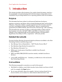
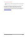
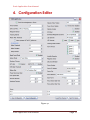
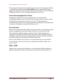
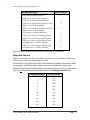
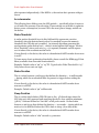
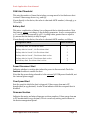
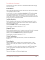
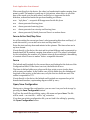
Revision Sheet 2.0 [Xact Application User Manual] This document illustrates how to configure the Trax device and what parameters can be changed to support the user application. Each configuration parameter is defined in this documentation and examples given in clear context. The level of this document is technical and our goal is to communicate how to easily change the operational behavior of the TRAX device. While this document addresses configuration parameters which changing these supports most applications and use cases, the next layer of control is available through our Open Source documents (located on the Developers Website), where the actual “C” source code may be modified and recompiled to give you the ultimate in application flexibility. Xact Application User Manual Page i Revision Sheet Revision History Version Date Revision Description 1.0 06/15/2011 First Version 1.9 10/11/2011 Intro, Accelerometer Examples Added 2.0 10/25/2011 Corrected Configuration Value to Match V3.05 Xact Application User Manual Page ii Revision Sheet Proprietary Notices Words and logos marked with ® or ™ are registered trademarks or trademarks owned by Xact Technology, LLC. Other brands and names mentioned herein may be the trademarks of their respective owners. Copyright © 2011 by Xact Technology, LLC. All rights reserved. No part of this publication may be reproduced, transmitted, transcribed, stored in retrieval systems, or translated into any language or computer language, in any form or by any means: electronic, mechanical, magnetic, optical, chemical, manual, or otherwise, without prior written permission from Xact Technology, LLC. The product described in this document is subject to continuous developments and improvements. Xact Technology, LLC in good faith, gives all particulars of the product and its use contained in this document. Xact Technology, LLC believes that the information in this manual is accurate. The document has been carefully reviewed for technical accuracy. In the event that technical or typographical errors exist, Xact Technology, LLC reserves the right to make changes to subsequent editions of this document without prior notice to holders of this edition. This document is intended only to assist the reader in the use of the product. This document is provided ―as is‖ with no warranties whatsoever, including any warranty of merchantability, non-infringement, fitness for any particular purpose, or any warranty otherwise arising out of any proposal, specification, or sample. Xact Application User Manual Page i Table of Contents REVISION HISTORY II TABLE OF CONTENTS 0 1. INTRODUCTION 3 PURPOSE 3 RELATED DOCUMENTS 3 CONVENTIONS 3 FEEDBACK & PROBLEM-REPORTING INSTRUCTIONS 4 2. OVERVIEW 5 INSTALLATION 5 RUNNING THE APPLICATION 5 3. THE APPLICATION 6 USB SERIAL PORT 7 PORT 7 BAUD RATE 7 PARITY 7 DATA BITS & STOP BIT 7 HANDSHAKING 7 AT COMMANDS 7 RESET DEVICE 7 FIRMWARE 8 CONFIGURATION 8 UPLOAD 8 DOWNLOAD 8 EDIT 8 WAYPOINTS 8 AGPS 9 Xact Application User Manual Page 0 Xact Application User Manual BAND 9 APN SETTINGS 9 4. CONFIGURATION EDITOR 10 SEND ACKNOWLEDGEMENT TO SERVER 11 FENCE NUMBER 11 SMS OR GPRS 11 WAYPOINT INTERVAL 12 TRACKING INTERVAL 13 MOTION ALERT THRESHOLD 13 ACCELEROMETER 14 WAKE THRESHOLD 14 WAKE DURATION 14 SLEEP DURATION 14 BREAD CRUMB MODE 15 SYSTEM MODE 15 NUMBER OF FENCES 15 GPS ALERT & AGPS OTA 15 GSM ALERT THRESHOLD 16 BATTERY ALERT 16 POWER DISCONNECT ALERT 16 OVER SPEED ALERT 16 FIRMWARE REVISION 16 HARDWARE REVISION 17 VIBRATION MOTOR PATTERN 17 POWER DOWN DISABLE 17 VIBRATION ENABLE 17 SOS ALERT 17 DOWNLOAD WAYPOINTS TO SERVER 17 LED EXERCISE 18 LED ACTIVATE 18 TRACKING MODE DURATION 18 ACTIVE FENCES 19 Xact Application User Manual Page 1 Xact Application User Manual INVISIBLE OPERATION 19 MAGNETIC SENSOR 19 CRITICAL CONFIRMATION 19 PHONE NUMBER 19 SERVER IP ADDRESS 19 SERVER PORT 20 FENCE DIRECTION 20 DAYS ACTIVE 20 FENCE ACTIVE START/STOP TIME 21 FENCE 21 OPEN/SAVE CONFIGURATION 21 LOAD FROM/SEND TO DEVICE 22 5. SAMPLE CONFIGURATIONS 23 APPENDIX A - CONFIGURATION FILE FORMAT 24 Xact Application User Manual Page 2 Xact Application User Manual 1. Introduction This chapter introduces this document, lists useful related documents, describes the typographic conventions being used in this document, and provides contact information for providing feedback on or reporting problems with this document. Purpose This document has been written for software and hardware developers, engineers, scientists, and others with a technical background who are developing Telemetry, Telematics, M2M, or wireless applications. This document assumes you have a working knowledge of GPS principles, wireless communications (particularly the GSM standard), basic electronics, Boolean logic, and computing. This document also assumes you have a working knowledge of basic software development tools. Also, the XACT USB Loader/Editor is required to make changes in the configuration file and a terminal program is recommended – HyperTerm, TerraTerm, PuTTY, or equivalent – will work just fine. Related Documents You may find the following documents helpful and these are available on the Xact Technology Website (xacttechnology.com): Xact Message Protocol Spreadsheet – XACT Tracker Protocol Rev T Xact Hardware Specification Document V1.6 Xact Hardware Schematic V2.1 MMA7455L Accelerometer Data Sheet, available from Freescale Semiconductor. WMP 100 GSM/GPRS/EDGE Rx wireless module, available from Sierra Wireless. u-blox AMY-5M GPS Receiver – Summary, available from u-blox and on the Xact Technology Website. Conventions The following typographic conventions are used in this manual: Field labels or window control labels (such as button labels) are shown in bold serif; for example, the Open button. Pre-set user-selectable values (for example, choices in a drop-down list) are shown in italics, as are numeric or other character data that can be sent Xact Application User Manual Page 3 Xact Application User Manual directly to a device; for example, select parity from None, Odd, Even, Mark, or Space. Hexadecimal numbers are shown with a leading ―0x‖; for example, 0x0404. Feedback & Problem-Reporting Instructions If you encounter any problems (errors, omissions, etc.) with this manual, please contact Xact Technology at the company‘s technical support email address: [email protected]. Xact Application User Manual Page 4 Xact Application User Manual 2. Overview The application is simple, consisting of only two windows: the main application window and the Configuration Editor. The application is a standard Windows executable, has no external dependencies (e.g., .Net, etc.), and should run on most configurations of Windows computers. Installation To install the application: 1. make sure the USB Windows Drivers are downloaded and installed (Sierra/Wavecom modem for the WMP100 Wireless Microprocessor); 2. download the XACT USB Loader application from the Xact Technology Website; 3. unzip the Zip file, making sure that the folder/directory structure is preserved; 4. run the setup.exe application. Once installed, the Start Menu in Windows will show the application. You can run it by selecting ―PC Loader‖ from the ―XACT‖ menu, under ―All Programs‖. A desktop icon is not created for the application. Also, there is no uninstaller; if you need to uninstall this application, do so from the Windows Control Panel > Add or Remove Programs. If Xact Technology releases a new version of the application, we recommend that you first uninstall the current version and install the new version, rather than installing the new version over the top of the existing application. Running the Application Before you run the application, make sure you install the USB driver for the device. This is also available from the Xact Technology Website, as a Zip file. The application will not work without the USB driver installed. Also, be sure that the Xact Development Board or other Xact device is connected to the computer‘s USB port before attempting to change any settings. There are no menus in this application; all the controls and editable fields are exposed in the application‘s windows. Xact Application User Manual Page 5 Xact Application User Manual 3. The Application Figure 3-1 Xact Application User Manual Page 6 Xact Application User Manual This chapter describes the data fields and controls in the main application window. USB Serial Port Before communicating with the Xact Development Board or other Xact device, you need to set up the USB Serial Port; this panel lets you do just that. The window is opened with most of the contents disabled; once the port is selected and enabled, the window‘s remaining controls and fields are enabled. Port If you already know the port to which the Board is connected, select it from the drop-down list. Else, press Scan to have the application search for ports and populate the list, then select from the list. Baud Rate (port speed) Select a default speed for the serial port. The choices available are 9600, 57600, and 115200. Parity Select from None, Odd, Even, Mark, or Space. Data Bits & Stop Bit Select the number of Data Bits from the spin box. Then select the Stop Bit; choices available are None, 1, 2, or 1.5. Handshaking Finally, select the handshaking mode; choose from XonXoff, RequestToSend (RTS), or RequestToSendXonXoff. AT Commands This is useful for sending ―one-way‖ AT commands to the device (such as to reset the device). Currently the response information from sending a command is not available, so this feature is of limited usefulness. Reset Device Resetting the device is accomplished by sending AT+CFUN=1 to the unit; releasing the battery connector on the PCB; or letting the battery completely discharge and recharge afterwards. Xact Application User Manual Page 7 Xact Application User Manual Firmware Here you can upload updated firmware to the device. Select the firmware binary (with a ―dwl‖ extension) by pressing the … button to show the file-open dialog. Select the file and press Open. Once the file path is shown in the ―Upload from:‖ field, press Upload to transfer the file to the device. Configuration This panel gives you three options to work with the device configuration: you can upload a configuration file to the device, download a configuration file from the device, or manually set the configuration via an editor. Upload Select the configuration text file (with a ―cfg‖ extension) by pressing the … button to show the file-open dialog. Select the file and press Open. Once the file path is shown in the ―Upload from:‖ field, press Upload to transfer the configuration to the device. Download Press the … button to show the file-save dialog. Enter a file name or select an existing file to overwrite and press Save. Once the file path is shown in the ―Save download to:‖ field, press Download to transfer the configuration from the device to your local storage. Edit You can set and change a wide range of device configuration options from the Configuration Editor, invoked by pressing the Open Editor button. The Editor is described in detail in Chapter 4 — Configuration Editor. Waypoints You can download GPS waypoints stored on the device to a file on your local storage. Press the … button to show the file-save dialog. Enter a file name or select an existing file to overwrite and press Save. Once the file path is shown in the ―Select file‖ field, press Download to transfer the waypoints from the device to your local storage. Xact Application User Manual Page 8 Xact Application User Manual AGPS ―AGPS‖ refers to Assisted GPS, which is a system that can improve the time-tofirst-fix (TTFF) for GPS. Whereas standalone GPS radio relies on signals from satellites, AGPS additionally uses network resources to locate and utilize the satellites faster — as well as better in poor signal conditions. To use this feature, you need to supply the latitude and longitude of the device. This is so that ephemeris data is sent only for those satellites currently visible to the mobile device requesting the data, thus minimizing the amount of data transferred (and thus cost as well). Additionally, login credentials (username and password) is embedded to access the u-Blox server with the ephemeris data and developers need to embed their own login/password in the application firmware. Currently we have a test accoount login/password. Band The Sierra Wireless WMP 100 GSM/GPRS/EDGE Rx microprocessor can operate on four frequency bands: 850, 900, 1800, and 1900 MHz. In this panel, you can get the device‘s current setting or set a new band or bands. To get the device‘s current setting, press Get Band Setting. The band(s) will be shown in the adjoining drop-down list. To set a new band or bands, select from the drop-down list; the available values are: 850, 900E, 1800, 1900, 850 and 1900, 900E and 1800, and 900E and 1900. Select the desired band(s) based on your wireless carrier and geographic region where the device operates. APN Settings ―APN‖ refers to Access Point Name, which is a configurable network identifier used by a mobile device when connecting to a GSM carrier. The carrier will then examine this identifier to determine what type of network connection should be created, for example: what IP addresses should be assigned to the wireless device, what security methods should be used, and other connection details. In this panel, you can get the device‘s current APN setting or set a different APN. To get the device‘s current settings, press the Get APN Settings button. The settings will be shown in the adjoining fields. To set a different APN, enter the address, username, and password in the labeled fields. The address must be in symbolic form (e.g., internet.mnc012.mcc345.gprs). Then press the Set APN Settings button to transfer the settings to the device. Xact Application User Manual Page 9 Xact Application User Manual 4. Configuration Editor Figure 4-1 Xact Application User Manual Page 10 Xact Application User Manual This chapter describes all the data fields and controls in the Configuration Editor — the window revealed when the Open Editor button is pressed in the main application window. For each setting, values are given both for choices within the Configuration Editor and for sending data directly to the device. Send Acknowledgement to Server Checking this checkbox forces the configuration to be recorded. The configuration packet is sent to the device, and a return code is sent to the server. If sent directly to the device, the value is „Y‟ or „N‟. „Y‟ indicates that the configuration packet has been accepted and loaded. If the packet was malformed or incorrect, the packet is sent back with this set to 'N'. Fence Number The Xact Development Board and Xact Trax device allow you to define geo-fences within a management portal (essentially soft fences) or on the device itself. The Configuration Editor enables a number of fence-related settings to be changed; for example, the fence direction, days active, fence latitude/longitude coordinates, and active fence start and stop times. For these settings, the fence to which they apply must be indicated, and this is done here. Select a fence number in the spinner. Up to 50 hardware fences are available. If sent directly to the device, the value is a hexadecimal ASCII number, from 0x00 to 0xFF. SMS or GPRS Indicates the roaming mode (allowed or not) and whether SMS is enabled as a fallback mechanism. Values are as follows, selected from the drop-down list: Xact Application User Manual Page 11 Xact Application User Manual Configuration Editor Direct to Device SMS mode roaming allowed 0 GPRS UDP mode roaming allowed 1 GPRS TCP mode roaming allowed 2 GPRS UDP mode roaming allowed, SMS fallback if no GPRS available 3 GPRS TCP mode roaming allowed, SMS fallback if no GPRS available 4 SMS mode no roaming allowed 5 GPRS UDP mode no roaming allowed 6 GPRS TCP mode no roaming allowed 7 GPRS UDP mode no roaming allowed, SMS fallback if no GPRS available 8 GPRS TCP mode no roaming allowed, SMS fallback if no GPRS available 9 If sent directly to the device, the value is a decimal ASCII number. Waypoint Interval Indicates the time interval, in seconds, at which to record waypoints. Select one of the pre-set values from the drop-down list. If sent directly to the device, the value is the hexadecimal number of seconds in ASCII. For example, 01E indicates that waypoints are to be recorded every 30 seconds. Note that waypoints are initially written to the onboard memory, into a circular buffer; they are not transmitted until an Event occurs. See Tracking Interval below. Configuration Editor Direct to Device 1 001 2 002 5 005 10 00A 15 00F 30 01E 60 03C 120 078 300 12C 600 258 Xact Application User Manual Page 12 Xact Application User Manual Tracking Interval Indicates an index corresponding to a time interval at which to transmit waypoint/tracking information, selected by the spinner. Configuration Editor Direct to Device 0 1 ”waypoint interval” – the device will send based on waypoint interval on the device 5 seconds 2 3 10 seconds 15 seconds 4 5 6 7 8 9 A B C D E F 30 seconds 45 seconds 1 minute 2 minutes 5 minutes 10 minutes 15 minutes 30 minutes 45 minutes 60 minutes 24 hours Reserved If sent directly to the device, the value is a decimal ASCII number. For example, a setting of 8 indicates that the device should transmit waypoint data every 5 minutes. Motion Alert Threshold A scalar motion threshold is set in this field and this represents a motion threshold, when the detected motion level is exceeded (crosses the numeric threshold, an event is generated and S-packet is immediately built and transmitted to the referenced portal. An internal algorithm generates this accelerometer scalar motion level –which is tested against this integer ―Motion Alert Threshold‖ where each axis (x, y, z) is squared, summed, and the square root is taken of the resultant motion levels. Example: Default value is ―0‖ or OFF. Typical value threshold is ―35‖. The checkbox Alarm operates WITHOUT geofences is used to indicate whether the motion alert is associated with the geofences or if the motion alarm is operating independently. The most significant bit (MSB) indicates if the motion alert is associated with the geofences or if the motion alarm is operating independently. If the MSB is 0, the Xact Application User Manual Page 13 Xact Application User Manual alert operates independently; if the MSB is 1, the motion alert operates with geofences. Accelerometer The following three fields govern the GPS module — specifically when it turns on or off under the presence of acceleration. These settings are available to optimize device power consumption, because GPS is the most power-hungry module on the device. Wake Threshold A scalar motion threshold is set in this field and this represents a motion threshold, when the detected motion level is exceeded (crosses the numeric threshold, the GPS chip set is enabled. An internal algorithm generates this accelerometer scalar motion level – which is tested against this integer ―Motion Alert Threshold‖ where each axis (x, y, z) is squared, summed, and the square root is taken of the resultant motion levels. If sent directly to the device, the value is a hexadecimal ASCII number from 0x00 to 0xFF. To learn more about acceleration thresholds, please consult the MMA7455L Data Sheet, available from Freescale Semiconductor. Example: Default value is ―20‖ or ―25‖FF. Typical value Wake Threshold is ―25‖. Only values above 0x16 are legal. Wake Duration This is a value between o and 65535 that defines the duration — in milliseconds — during which the acceleration must be present to trigger before waking the GPS. If sent directly to the device, the value is a hexadecimal ASCII number from 0x0000 to 0xFFFF. Example: Default value is ―40‖ milliseconds. Sleep Duration This is a value which defines GPS ON time-to-live. 3D Search time where the GPS chip set is fully powered and searching the sky for four satellites minimum (3D fix). Software defined as ―fast-idle‖ or full power mode. Defined value between o and 65535 that defines the duration — in seconds — during which no motion is to be detected before the GPS is back to sleep (slow-idle) mode. If sent directly to the device, the value is a hexadecimal ASCII number from 0x0000 to 0xFFFF. Example: Default value is ―180‖ seconds or 3 minutes. Xact Application User Manual Page 14 Xact Application User Manual Bread Crumb Mode Configuration Editor Direct to Device 0 1 2 bread crumb mode not active, no special case bread crumb mode active, no special case bread crumb mode not active, fence active start time = 0x5F 3 4 bread crumb mode not active, fence active stop time = 0x5F bread crumb mode not active, fence active start, stop time = 0x5F 5 6 7 bread crumb mode active, fence active start time = 0x5F bread crumb mode active, fence active stop time = 0x5F bread crumb mode active, fence active start, stop time = 0x5F System Mode Sets the device‘s current mode. Values are: Walk Mode, Track Mode, Dog Park Mode, Request Tracking Bundle, Request Tracking Bundle with Vibrate, and Don‟t Update. Leave this set to Don‟t Update. If sent directly to the device, the value is a decimal ASCII number (‗0‘). Number of Fences Indicates how many geo-fences you have defined. Values range from 0 to 50, set by the spinner. If sent directly to the device, the value is a hexadecimal ASCII number from 0x00 to 0x32. GPS Alert & AGPS OTA Enable or disable an alert if GPS coverage is lost. This alert may be augmented with Over-The-Air Assisted GPS (OTA AGPS). If sent directly to the device, the value is a decimal ASCII number, as follows: Value GPS Alert OTA AGPS 0 On On 1 On Off 2 Off On 3 Off Off Note: with OTA AGPS enabled, more data is being sent across the network, which may have cost implications depending on the data plan selected for your application. Xact Application User Manual Page 15 Xact Application User Manual GSM Alert Threshold This sets the number of times that wireless coverage must be lost before an alert is raised. Values range from 1 to 5, and Off. If sent directly to the device, the value is a decimal ASCII number (1 through 5, or „N‟ for Off): Battery Alert This sets a combination of battery low-voltage and device shutdown alerts. Note that battery voltage, not charge, is the defining parameter. Level 1 corresponds to 3.7V, and Level 2 corresponds to 3.8V. A voltage value greater than or equal to 3.9 means that the battery is fully charged. If sent directly to the device, the value is a decimal ASCII number, as follows: Configuration Editor Direct to Device No Battery Alert, No Shutdown Alert 0 Battery Alert at Level 1, No Shutdown Alert 1 Battery Alert at Level 2, No Shutdown Alert 2 Battery Alert at Level 1, Shutdown Alert active 3 Battery Alert at Level 2, Shutdown Alert active 4 No Battery Alert, Shutdown Alert active 5 Power Disconnect Alert Indicates whether to send an alert when the power is disconnected. Check the Enabled checkbox to enable the alert. Note that the power being referred to is the external 5V USB power threshold, not the internal power supply. Over Speed Alert Sets the speed at which the alert is triggered. Values range from 00 to FF hexadecimal (0-255 decimal). A value of 00 indicates that the overspeed alert is disabled. Firmware Revision Indicates the major and minor firmware revision numbers. Values range from 00 to FF hexadecimal (0-255 decimal). This is a read-only setting, and is shown in the device management portal. Xact Application User Manual Page 16 Xact Application User Manual Hardware Revision Indicates the major and minor hardware revision numbers. Values range from 00 to FF hexadecimal (0-255 decimal). This is a read-only setting, and is shown in the device management portal. Vibration Motor Pattern Sets the vibration pattern (rate at which vibration pulses are generated) for the internal vibration motor. Values range from 1 to 9, each corresponding to a particular pattern. Power Down Disable Indicates whether to disable the device buttons and use fake power-down mode. Check the Power Down Disabled checkbox to disable the device buttons and use fake power-down mode. If sent directly to the device, the value is „Y‟ or „N‟. Vibration Enable Indicates whether to enable device vibration for geo-fence violations. Check the Enabled checkbox to enable vibration when a geo-fence is violated. If sent directly to the device, the value is „Y‟ or „N‟. SOS Alert Indicates whether to enable the SOS alert. The SOS alert is generated when a user presses the large ―panic button‖ on the Xact Trax device, or the corresponding switch is pressed on the Xact Development Board. Check the Enabled checkbox to enable the alert. If sent directly to the device, the value is „Y‟ or „N‟. Download Waypoints to Server This defines the amount of waypoint data to download from the device. Choices comprise All Data, 1 Week, 3 Days, 1 Day, 8 Hours, or 1 Hour. Note that waypoints are initially written to the onboard memory, into a circular buffer; they are not transmitted. See also Tracking Interval and Waypoint Interval above. If sent directly to the device, the value is an ASCII character, as follows: Xact Application User Manual Page 17 Xact Application User Manual Configuration Editor Direct to Device Do not download 0 1 Hour 1 8 Hours 8 24 Hours (1 Day) 2 72 Hours (3 Days) 7 1 Week W All Data A LED Exercise Turn LEDs on and off according to a pattern. Values range from 1 to 9, each corresponding to a particular pattern. Select the pattern from the dropdown list. There are nine possible patterns because there are three LEDs, each of which can display three states: off, red, or green. If sent directly to the device, the value is a decimal ASCII number. A value of 0 will result in no change to the pattern setting. LED Activate Activate or deactivate each LED. The LEDs are activated or deactivated by checking/ unchecking the checkboxes corresponding to each LED. LEDs can also be programmatically activated or deactivated by sending a hexadecimal ASCII value. Values range from 00 to 3F hexadecimal. The bit settings are defined by the following table: LED Red Green Power 01 02 GSM 04 08 GPS 10 20 To turn on an LED, perform a logical OR for the LED and color setting. To turn off an LED, clear the bits. For example, to turn the GPS LED to red and the GSM to green, send hexadecimal 18. Tracking Mode Duration This is the number of 10-second intervals to keep tracking mode active. Values range from 0 to 8640 (which is 24 hours), selected by the spinner. A value of 0 will keep tracking mode on indefinitely. Xact Application User Manual Page 18 Xact Application User Manual If sent directly to the device, the value is a hexadecimal ASCII number ranging from 0000 to 210C. Active Fences This scrolling list indicates the geo-fences that are active. An active fence has its corresponding checkbox checked. If sent directly to the device, the value is a hexadecimal ASCII number ranging from 0x00000000000000 to 0xFFFFFFFFFFFFFF, where a bit position corresponds to a fence number. For example, to have fences 3 and 11 active, the binary value would be 000000000000000000000000000000000000000100 00000100, which is 0x00000000000404. Invisible Operation Enable or disable invisible operation. Invisible operation prevents the device from turning off when the power button is held; instead, the device appears to power off but in fact does not. Check the Enabled checkbox to enable invisible operation. If sent directly to the device, the value is „Y‟ or „N‟. Magnetic Sensor Enable or disable magnetic sensor. A magnetic sensor could be used, for example, to detect when the device has been removed from a holder or mount. Check or uncheck the Enabled checkbox for the desired operation. If sent directly to the device, the value is „Y‟ or „N‟. Critical Confirmation Set this to Off. If sent directly to the device, the value is the ASCII decimal number 0. Phone Number The server phone number, without spaces, parentheses, dashes, or other separators. This is the phone number or shortcode at which to receive SMS messages. If sent directly to the device, the value is expressed as 14 ASCII decimal digits (bytes). Short numbers are padded with leading zeros to fill the 14 bytes. Server IP Address The server‘s IP address, in IPV4 dotted-quad format. Xact Application User Manual Page 19 Xact Application User Manual If sent directly to the device, the value is a hexadecimal ASCII number from 0x00000000 to 0xFFFFFFFF. For example, the IP address expressed as a dotted quad, 98.216.231.125, would be represented as 0x62D8E77D. Server Port The server port number. If sent directly to the device, the value is a ASCII hexadecimal number ranging from 0x0000 to 0xFFFF. For example, port 525 would be represented 0x020D. Fence Direction This indicates the ―direction‖ of a device in motion that raises a geo-fence violation alert. Selectable values are: Safe Fence (magnetic SOS suppressed inside this fence) Alarm generated leaving fence Alarm generated entering fence Alarm generated on entering and leaving fence Alarm generated inside fence with motion alarm When sending directly to the device, calculate the raw binary value for this field according to the bitfield description below (under Days Active), then add an offset of 0x20 to get the Latin-1-character compatible value for the message. When receiving, subtract the offset 0x20 and process according to the bitfield definitions. Days Active This indicates the days of the week during which a geo-fence is active. The values are as follows: Configuration Editor Direct to Device All days 0000 Monday, Wednesday, Friday Tuesday, Thursday 0001 0010 Monday through Friday Saturday through Sunday Monday 0011 0100 0101 Tuesday Wednesday Thursday 0110 0111 1000 Friday Saturday Sunday 1001 1010 1011 Xact Application User Manual Page 20 Xact Application User Manual When sent directly to the device, the value is a hexadecimal number ranging from 0x20 to 0x6B. The number is made up of a bit pattern, where bits 0 to 3 are the days of the week, as in the table above, and bits 4 to 6 represent the fence direction, as described under the previous heading, as follows: 000 “safe fence” — magnetic SOS suppressed inside this fence 001 alarm generated leaving fence 010 alarm generated entering fence 011 alarm generated on entering and leaving fence 100 alarm generated if inside fence and there is a motion alarm Fence Active Start/Stop Time As well as setting the current geo-fence‘s alert-generating direction and day(s) of week when active, you can also set a start and stop time for it. Enter the start and stop hour and minute in the spinners. The time values are in 24-hour format. If sent directly to the device, the start and stop time fields are each represented as hexadecimal ASCII numbers, ranging from 0x20 to 0x7E. The value is calculated by first calculating the number of 15-minute intervals from midnight, then adding a constant offset of 0x20 to make a Latin-1-compatible character. Fence The latitude and longitude for the current fence are displayed at the bottom of the Configuration Editor. If the fence is not set, the fields are all zero. The fence is defined either as a polygon with four points or as a circular fence with a center and radius. In the former case, all four fields show the latitude and longitude of the points; in the latter case, only the first two fields are used. The radius is expressed in ????. If sent directly to the device, the latitude and longitude are expressed as 32-bit hexadecimal numbers, representing degrees offset by 10e-7. Open/Save Configuration Having set or changed the configuration, you can save it on your local storage by pressing the Save Configuration button. You‘ll see the usual file-save dialog; enter a file name and press Save. The file will be saved — as a text file — with a ―cfg‖ extension. If you have an existing configuration file, you can load it for editing by pressing the Open Configuration button. Xact Application User Manual Page 21 Xact Application User Manual You‘ll see the usual file-open dialog; select a file (only files with a ―cfg‖ extension are initially shown) or enter a file name and press Open. The file‘s contents will be loaded and the Editor‘s fields set accordingly. Load From/Send To Device Having set or changed the configuration, you can install it on the device by pressing the Send To Device button. And if you wish to retrieve the device‘s current configuration for editing, press the Load From Device button. Xact Application User Manual Page 22 Xact Application User Manual 5. Sample Configurations (This chapter currently unavailable) Xact Application User Manual Page 23 Xact Application User Manual Appendix A - Configuration File Format The device configuration file as created by the application is simply a text file with a continuous stream of ASCII characters. The format of the file is shown below. Field Flag1 Flag2 Type Send Acknowledgement to Server Fence number SMS or GPRS Waypoint Interval Tracking Interval Motion Alarm Threshold Accelerometer Wake Threshold Accelerometer Wake Duration Accelerometer Sleep Duration Breadcrumb Mode System Mode Number of Fences GPS Alert GSM Alert Threshold Battery Alert Power Disconnect Alert Over Speed Alert Firmware Revision Hardware Revision Reserved Power Down Disable Vibration Motor Pattern Vibration Enable SOS Alert Waypoint Download LED Exercise LED Activate Tracking Mode Duration Active Fences Invisible Operation Magnetic Sensor Xact Application User Manual Bytes Characters Offset Count 1 1 1 1 2 1 1 1 1 1 1 1 1 1 1 1 1 1 1 1 1 1 1 1 1 1 1 1 1 1 1 1 1 1 2 1 3 1 2 2 4 4 1 1 2 1 1 1 1 2 2 2 1 1 1 1 1 1 1 2 4 14 1 1 0 1 2 3 4 6 7 10 11 13 15 19 23 24 25 27 28 29 30 31 33 35 37 38 39 40 41 42 43 44 46 50 64 65 1 2 3 4 6 7 10 11 13 15 19 23 24 25 27 28 29 30 31 33 35 37 38 39 40 41 42 43 44 46 50 64 65 66 1 1 Page 24 Xact Application User Manual Field Critical Confirmation Server Phone Number Server IP Address Server Port Number Fence Direction and Day(s) of Week Latitude Longitude Latitude Longitude Latitude Longitude Latitude Longitude Fence Active Start Time Fence Active Stop Time Xact Application User Manual Bytes Characters Offset Count 1 1 14 8 4 1 8 8 8 8 8 8 8 8 1 1 66 67 81 89 93 94 102 110 118 126 134 142 150 158 159 67 81 89 93 94 102 110 118 126 134 142 150 158 159 160 1 4 4 4 4 4 4 4 4 1 1 Page 25