1
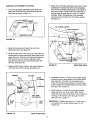
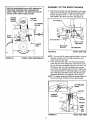
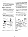
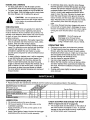
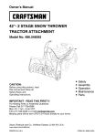
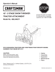
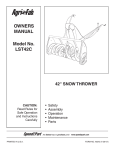
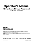
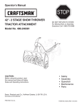
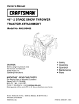
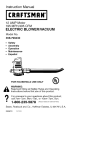
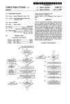
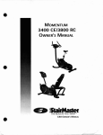
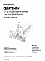
Owner's Manual
CRAFTSMAN
40"- 2 STAGE SNOW THROWER
TRACTOR
ATTACHMENT
Model No. 486.24839
•
•
•
•
CAUTION:
Before using this product,
read this manual and follow
all Safety Rules and
Operating Instructions.
Sears, Roebuck and Co., Hoffman
pRINTED
IN U.S.A.
Safety
Assembly
Operation
Maintenance
• Parts
Estates, IL 60179 U.S.A.
ACCESSORIES ...........................................................
SAFETY RULES ..........................................................
FULL SIZE HARDWARE CHART .................................
CARTON CONTENTS .................................................
ASSEMBLY .................................................................
OPERATION ............................................................
MAINTENANCE .........................................................
LIMITED ONEYEAR
WARRANTY
2
3
4
5
5
18
19
SERVICE AND ADJUSTMENTS ................................
20
STORAGE .................................................................
21
TROUBLESHOOTING
...............................................
21
REPAIR PARTS ILLUSTRATION ......................... 22,2z
REPAIR PARTS LIST ...........................................
23,25
SLOPE GUIDE ..........................................................
27
PARTS ORDERING/SERVICE
................ BACK COVER
ON 40" 2-STAGE SNOWTHROWER
For one year from the date of purchase, when this snow thrower is maintained and lubricated according to the operating
and maintenance instructions in the owner's manual, Sears will repair any defect in material or workmanship free of charge.
If this snow thrower is used for commercial or rental purposes, this warranty applies for only 90 days from the date of
purchase.
This warranty does not cover repairs necessary because of operator negligence or abuse, including the failure to maintain
the equipment according to instructions contained in the owner's manual.
WARRANTY SERVICE iS AVAILABLE BY CONTACTING THE NEAREST SEARS SERVICE CENTER/DEPARTMENT
IN THE UNITED STATES.
This warranty applies onty while this product is in the United States.
This warranty gives you specific legal rights, and you may also have other rights which vary from state to state.
Sears, Roebuck and Co. D/817 WA. Hoffman Estates, Chicago, IL 60179
These accessories were available when the unit was purchased. They are also available at most Sears retail outlets
and service centers. Most Sears stores can order repair parts for you when you provide the model numbers of your
tractor and snow thrower.
WHEEL
WEIGHT
TIRE CHAINS
The model number and serial numbers will be found on a
decal attached to the snow thrower.
You should record both the serial number and the date of
purchase and keep in a safe place for future reference.
DRIFT CUTTER BARS
KIT NO. 71-88294
MODEL NUMBER:
SERIAL NUMBER:
DATE OF PURCHASE:
486.24839
Any power equipment can cause injury if operated improperly or if the user does not understand
the equipment. Exercise caution at all times, when using power equipment.
•
•
•
•
•
•
•
•
•
•
•
•
•
•
•
•
•
•
Read this owner's manual carefully and know how
to operate your snow thrower and how to stop the
unit and disengage the controls quickly.
Never allow children to operate the equipment.
Never allow adults to operate the equipment
without proper instruction.
Keep the area of operation clear of all persons,
especially small children, and pets.
Thoroughly inspect the area where the equipment
is to be used and remove all door mats, sleds,
boards, wires and other foreign objects.
Disengage all clutches and shift into neutral before
starting engine.
Do not operate equipment without wearing adequate winter outer garments.
Wear substantial footwear which will protect feet
and improve footing on slippery surfaces.
Check fuel before starting the engine. Do not
remove the fuel cap or fill the fuel tank while the
engine is running or hot. Do not fill the fuel tank
indoors. Gasoline is an extremely flammable fuel.
Make sure the snow thrower height is adjusted to
clear the type surface it will be used on.
Do not use the snow thrower without the rear
weight attached to the tractor.
Never make any adjustments while the engine is
running.
Always wear safety glasses or eye shield during
operation or while performing and adjustment or
repair.
Do not place hand or feet near rotating parts. Keep
clear of the discharge opening at all times.
Use extreme caution when operating on or crossing
gravel surfaces.
Do not carry passengers.
After striking a foreign object, stop the engine,
remove the wire from the spark plug and then
thoroughly inspect the snow thrower for damage.
Repair any damage before restarting and operating
the snow thrower.
If the snow thrower starts to vibrate abnormally,
stop the engine immediately and check for the
cause. Vibration is generally a warning of trouble.
hew to operate
Stop the engine whenever you leave the operating
position, before unclogging the snow thrower or
making any adjustments or inspections.
Take all possible precautions when leaving the unit
unattended. Disengage the attachment clutch lever
or switch, lower the snow thrower, shift into neutral,
set the parking brake, stop the engine and remove
the key.
When cleaning, repairing or inspecting, make
certain all moving parts have stopped. Disconnect
the spark plug wire and keep it away from the plug
to prevent accidental starting.
Do not run engine indoors except when transporting the snow thrower in or out of the building. Open
the outside doors. Exhaust fumes are dangerous.
Do not clear snow across the face of slopes.
Exercise extreme caution when changing direction
on slopes. Do not attempt to clear steep slopes.
Refer to the slope guide on page 27 of this manual.
Never operate the snow thrower without guards,
plates or other safety protection devices in place.
Never operate the snow thrower near glass enclosures, automobiles, window wells, drop offs etc.
without proper adjustment of the snow thrower
discharge angle.
Never direct discharge at bystanders or allow
anyone in front of the snow thrower.
Never run the snow thrower into material at high
speeds.
Do not overload the machine capacity by attempting to clear snow at too fast a rate.
Never operate the machine at high transport speed
on slippery surfaces. Look behind and use care
when backing.
Watch for traffic and stay alert when crossing or
operating near roadways.
Disengage power to the snow thrower when transporting or when not in use.
Use only attachments and accessories approved by
the manufacturer of the snow thrower (such as
wheel weights, counter weights, cabs etc.)
Never operate the snow thrower without good
visibility or light.
I
Look for this symbol to point out important
Become alert!! Your safety is involved.
safety precautions.
It mean--Attention!!
I
h
SHOWN
ACTUAL
SIZE
SPARE PARTS BAG
Store these two bolts and nuts In a safe
place until needed. (See page 20.)
/CC
NOT SHOWN
ACTUAL
SIZE
/ FF
.EE
REF.
A
B
C
D
E
F
G
H
I
J
K
L
M
N
O
P
Q
R
QTY.
DESCRIPTION
1
Hex Bolt, 1/2" x 1-1/4"
4
Hex Bolt, 3/8" x 1"
2
, Hex Bolt, 5/16" x 1-3/4"
6
Hex Bolt, 1/4" x 1"
2
Slotted Truss Head Bolt, 3/8" x 1"
4
Carriage Bolt, 3/8" x 1"
2
Carriage Bolt, 5/16" x 1-3/4"
2
Carriage Bolt, 5/16" x 1-1/4"
6
Carriage Bolt, 5/16" x 1"
2
Carriage Bolt, 5/16" x 3/4"
4
Shoulder Bolt, 3/8" x 5/8"
10
Lock Washer, 3/8"
14
Lock Washer, 5/16"
1
Lock Washer, 1/2"
2
Washer, 1/2"
7
Washer, 1/4"
2
Washer, 5/16"
2
Bowed Washer
REF.
S
T
U
V
W
X
Y
Z
AA
BB
CC
DD
EE
FF
GG
HH
II
JJ
KK
QTY.
1
6
12
4
11
1
3
3
1
2
1
1
3
1
1
1
2
1
2
/oo
_ KK
DESCRIPTION
Washer, 3/8"
Hex Lock Nut, 1/4"
Hex Nut, 5/16"
Hex Lock Nut, 5/16" (2 pcs. spare parts)
Hex Lock Nut, 3/8"
Hex Nut, 1/2"
Hairpin Cotter, 5/64"
Hairpin Cotter, 1/8"
Hairpin Cotter, 3/32"
Shear Bolt (spare parts)
Tarp Strap
Spring
Chute Keeper
Chain, Tensioning
Trunnion
Spacer
Lock Pin
Plastic Cap
Nylon Tie
CARTON
1.
2.
3.
4.
5.
6.
7.
8.
9.
10.
CONTENTS
Cross Brace (Weight Tray)
Side Brace (Weight Tray)
Right Hand Side Plate (Stamped "R")
Left Hand Side Plate (Stamped "L")
Anti-rotation Bracket
Engagement Rod (Not used on some models)
Engine Pulley Keeper
Chute Crank Rod Assembly
Support Tube, Crank Rod
Lift Handle Tube and Cable
16
11.
12.
13.
14.
15.
16.
17.
18.
Cable Bracket
Plastic Keg
Left Hand Hanger Bracket (Stamped "L")
Right Hand Hanger Bracket (Stamped "R ")
Clutch Idler Assembly
V Belt, Drive
V Belt, Auger (Attached to Housing Assembly)
Chute and Control Cable Assembly
19.
20.
Housing Assembly
Weight Tray
Hardware Package (Stored inside Plastic Keg)
TOOLS
(2)
(2)
(2)
(2)
(1)
REQUIRED
ASSEMBLY OF SIDE PLATES TO TRACTOR
FOR ASSEMBLY
Right hand (R,H.) and left hand (L.H.) side of the tractor
are determined from the operators position while seated
on the tractor.
7/16" Wrenches
1/2' Wrenches
9/16" Wrenches
3/4" Wrenches
Knife
ADDITIONAL
TRACTORS WITH FRAME MOUNTED FRONT
SUSPENSION BRACKETS
(See page 7 for tractors
with axle mounted front suspension brackets.)
ITEMS REQUIRED
•
General Purpose Grease
REMOVAL
•
OF PARTS
Remove two bolts from each side of the tractor
frame as shown in figure 1.
FROM CARTON
REMOVE BOLTS FROM THESE HOLES
Remove all parts and hardware packages from the
carton. Lay out parts and hardware and identify using
the illustrations on pages 4 and 5.
NOTE: Not all of the supplied parts and hardware
will be needed for your particular tractor. Unneeded
items may be discarded after you have completed
assembly.
&
TRACTOR
FRONT
SUSPENSION
BRACKET
CAUTION:
Before starting to assemble
the snow thrower, remove the spark plug
wire(s), set the parking brake and
remove the key from the tractor ignition.
FIGURE 1
Assemble the R.H. Side Plate (marked "R") to the
now empty holes in the right side of the tractor frame.
Use two 3/8" x 1" hex bolts and 3/8" lock washers as
shown in figure 2. Repeat for the L.H. side.
PREPARATION
Before performing these instructions, refer to the Service
and Adjustments section of your tractor owner's manual
for specific safety instructions.
•
Allow engine, muffler and exhaust deflector to cool
before beginning.
•
Remove any front or rear attachment which is
mounted to your tractor.
•
Remove the mower deck. Refer to your tractor
owner's manual for removal instructions. Mark all
loose parts and save for re-assembly.
•
Remove the tractor hood and grill assembly. Refer to
your tractor owner's manual for removal instructions.
ITEMS REMOVED
RIGHT SIDE VIEW
NOTE: If the side plates are later removed from
the tractor frame, bolts must be assembled back
into the empty holes in the frame.
3_"LOCK
WASHER
3/8"x1"
HEXBOLT
FROM TRACTOR
Store all parts that you remove from the tractor and do
not re-use while assembling the snow thrower.
R.H. SIDE
PLATE
\
,,
FIGURE 2
6
I
RIGHT SIDE VIEW
Assemble a shoulder bolt, a 3/8" lock washer and a
3/8" hex lock nut to the bottom hole in each side
plate. See figure 3.
Attach the R.H. Side Plate (marked "R") to the right
side of the tractor frame as shown in figure 5. For the
front hole use a 3/8" x 1" hex bolt, a 3/8" lock washer,
a 1/2" flat washer and a 3/8" hex lock nut. Use the flat
washer as a shim between the frame and the side
plate. For the rear hole use a 3/8" x 1" hex bolt, and a
3/8" lock washer. Repeat for the L.H. side.
Proceed to page 8.
3_" HEX LOCK NUT
NOTE: Depending on the tractor model, the bolt
may insert freely into the front hole or it may screw
into the hole. If the hole is not threaded, the bolt
will form threads as it is screwed in.
3_"LOCK
WASHER
I_"FLAT
WASHER
_8"LOCK
WASHER
R. H. SIDE PLATE
3/8" SHOULDER BOLT
FIGURE 3
3/8"HEX
LOCK NUT
RIGHT SIDE VIEW
3/8" x 1"
HEX BOLT
R.H. SIDE
PLATE
FIGURE 5
TRACTORS WITH AXLE MOUNTED
SUSPENSION BRACKETS
FRONT
•
•
RIGHT SIDE VIEW
Remove the bolt from the hole on each side of the
tractor frame as shown in figure 4.
Assemble a shoulder bolt, a 3/8" lock washer and a
3/8" hex lock nut to the bottom hole in each side
plate. See figure 6.
3/8"HEXLOCKNUT
REMOVE BOLT FROM
THIS HOLE
_8"LOCK
WASHER
FRONT
SUSPENSION
BRACKET
R.H. SlDE PLATE
3/8" SHOULDER
FIGURE 4
BOLT
RIGHT SIDE VIEW
FIGURE 6
7
RIGHT
SIDE VIEW
INSTALLING
HANGER
INSTALLING
BRACKETS
For better clearance, lower the tractor's suspension
arms using the attachment lift lever.
On Tractors With Foot Rest Brackets
•
•
(Figure 7)
Remove the bolt and nut that fasten the L.H. and
R.H. foot rest brackets to the frame. See figure 7.
Attach the L,H. Hanger Bracket (marked "L') to the
inside of the tractor frame using two 3/8" x 1"
carriage bolts, 3/8" lock washers and 3/8" hex lock
nuts. The bolt heads go on the inside of the tractor
frame. Repeat for the R.H, side. See figure 7.
3/8" LOCK
WASHER
BOLT REMOVED
. FROM THIS HOLE
--_.,_
SHOULDER
BOLTS
All Tractors
• Remove the bolt, washer and nut which fasten the
sway bar bracket to the L.H. side of the tractor
frame. Replace with a shoulder bolt and a 3/8" hex
lock nut as shown in figure 9.
/
/
3/8" HEX
SHOULDER BOLT
I
\
BOLTREMOVED
FROM THIS HOLE
_.
FIGURE 9
!
3/8" x 1"
CARRIAGE
ROlL T
SWAY BAR
\
BRACKET
L_CKNUT
LEFT SIDE VIEW
t
SUSPENSION
L.H. HANGER
BRACKET
ARM
Assemble a shoulder bolt and 3/8" hex lock nut to
the R.H. side of the tractor frame, using the first
empty hole to the rear of the R.H. hanger bracket.
See figure 10.
_
FIGURE 7
LEFT SIDE VIEW
On Tractors Without Foot Rest Brackets (Figure 8)
• Find the empty hole beneath the foot rest, Attach
the LH. Hanger Bracket (marked "L") to the inside
of the frame using a 3/8" x 1" carriage bolt (head to
inside), a 3/8" lock washer and a 3/8" hex lock nut.
See figure 8. Repeat for the R,H. side.
3/8" LOC_
WASHER
3/8"HEX
Replace the engine pulley keeper on your tractor
with the new pulley keeper supplied with the snow
blower. Attach the keeper to the frame using the
original bolt, washer and nut. See figure 10.
NOTE: Some tractors may already be equipped
with an identical pulley keeper.
ORIGINAL BOLT,
NUT AND WASHER
_3/8
HEX
LOCK NUT
I
SUSPENSION
3/8"x1"
L.H. HANGER
CARRIAGE
BOLT
BRACKET
FIGURE 8
ARM
_
"_
LEFT SIDE VIEW
FIGURE 10
RIGHT SIDE VIEW
INSTALLING
CLUTCH/IDLER
ASSEMBLY
This section covers the installation of the Clutch/Idler
assembly to tractors with attachment clutches that are
either rod operated (p, 9), cable operated (p. 10) or
electric (p. 12). Use the appropriate instructions for
your tractor.
ROD OPERATED
•
ATTACHMENT
CLUTCHES
Attach the snow thrower's clutch/idler assembly to
the tractor frame by sliding the notched arms at the
rear of the assembly onto the two shoulder bolts
assembled to the inside of the tractor frame. Lift
the front of the assembly, fitting the sides into the
R.H. and L.H. hanger brackets. Attach the assembly to the brackets using two pivot lock pins and
1/8" hairpin cotters. See figure 12.
1/8" HAIRPIN COTTER
Move the attachment clutch lever on the dash
panel to the disengaged (down) position.
Screw the trunnion
PIVOT LOCK PIN
ENGAGEMENT
ROD
onto the end of the snow
thrower engagement
rod as shown in figure 11.
Locate the clutch arm which is found underneath
the right hand side the tractor, just to the inside of
the suspension arm. This is the arm that the mower
clutch rod was connected to. The arm moves
forward and backward as the attachment clutch
lever on the dash panel is moved.
Position the engagement rod to the inside of the
clutch arm and insert the drilled end of the rod
through the arm. Secure with a 5/64" hairpin cotter.
See figure 11.
ENGAGEMENTROD
TRACTOR'S CLUTCH ARM
/
5/64" HAIRPIN
COTTER
\
SUSPENSION ARM
FIGURE 11
FIGURE 12
RIGHT SIDE VIEW
Make sure the attachment clutch lever on the dash
panel is in the disengaged (down) position.
Pivot the upper idler arm so that it rests against the
stop bolt and is pointing toward the front as shown
in figure 13. Screw the trunnion along the threads
of the engagement rod until it is aligned at the front
end of the idler arm slot. Attach the trunnion to the
slot using the 3/8" flat washer and a 5/64" hairpin
cotter. See figure 13.
RIGHT SIDE VIEW
Be sure that the loose end of the engagement rod
is lifted up toward the front of the tractor (as shown
in figure 12) when performing the next operation.
You can temporarily support the rod using a rubber
band tied to the engine pulley keeper.
IDLER ARM
3/8" FLAT
_
WASHER
5/64" HAIRPIN
COTTER
FIGURE 13
RIGHT SIDE VIEW
Assemblethe
CABLE OPERATED
short "V" belt onto the engine pulley
and then onto the large pulley on top of the clutch/
idler assembly. The belt must be placed to the
inside of the engine pulley keeper, the idler pulley
and the keeper bolt located beside the large pulley.
See figure 14.
A'n'ACHMENT
CLUTCHES
Assemble the cable bracket to the clutch/idler
assembly using two 5/16" x 3/4" carriage bolts,
5/16" lock washers and 5/16" hex Iocknuts. Use the
two front holes in the cable bracket if your tractor
has a 42" mower deck. Use the two rear holes if
IMPORTANT:
Do Not assemble the "V" belt
around the outside of the enaine pulley keeper or
the keeper bolt.
your tractor has a 46" mower deck. See figure 15.
5/16" x 3/4"
CARRIAGE BOLT
Hold this drawing above you while viewing the
Clutch/Idler Assembly from underneath the
tractor, Right and left in the drawing will be the
reverse of the viewer's right and left.
ENGINE
PULLEY
KEEPER
Left Side
of Tractor
5/16" LOCK
WASHER
;/16" HEX
LOCK NUT
ENGINE
PULLEY
FIGURE 15
•
•
•
•
BOLT
FIGURE 14
•
Move the attachment clutch lever on the dash panel
to the disengaged (down) position.
Lay the clutch/idler assembly beneath the tractor.
Attach the tractor's clutch cable to the cable
bracket. Secure the cable housing guide (groove
down) to the cable bracket using the original collar
and retainer spring removed from the mower deck.
See figure 16.
Place a spacer on the welded pin on the idler arm.
Hook the end of the ctutch spring over the pin and
secure it with a 1/4" washer and a 5/64" hair cotter
pin. See figure 16.
5/64" HAIR
COTTER PIN
VIEWED FROM UNDERNEATH
Proceed to page 13.
SPACER
/
TRACTOR'S
CLUTCH CABLE
FIGURE 16
10
Attach the clutch/idler assembly to the tractor frame
by sliding the notched arms at the rear of the
assembly onto the two shoulder bolts assembled
to the inside of the tractor frame. Lift the front of
the assembly, fitting the sides into the R.H. and
L.H. hanger brackets. Attach the assembly to the
brackets using two pivot lock pins and 1/8" hairpin
cotters. See figure 17.
Assemble the short "V" belt onto the engine pulley
and then onto the large pulley on top of the clutch/
idler assembly. The belt must be placed to the
inside of the engine pulley keeper, the idler pulley
and the keeper bolt located beside the large pulley.
See figure 18.
IMPORTANT:
Do Not assemble
the "V" belt
around the outside of the engine pulley keeper or
the keeper bolt.
1/8" HAIRPIN COTI'ER
Hold this drawing above you while viewing the
Clutch/Idler Assembly from underneath the
tractor. Right and left in the drawing will be the
reverse of the viewer's right and left,
PIVOT LOCK PIN
ENGINE
PULLEY
Left Side
of Tractor
KEEPER _
ENGINE
_j
b
4_
PULLEY
f
IDLER
BOLT
FIGURE 17
FIGURE 18
•
11
VIEWED FROM UNDERNEATH
Proceed to page 13.
ELECTRIC
•
A'n'ACHMENT
CLUTCHES
•
Turn the clutch/idler assembly upside down and
place the extra tensioning chain through the left
front hole as shown in figure 19.
Attach the clutch/idler assembly to the tractor frame
by sliding the notched rear arms of the assembly
onto the two shoulder bolts placed on the inside of
the tractor frame. Lift the front of the assembly so
that the sides fit inside the R.H. and L.H. hanger
brackets. Attach the assembly to the brackets
using two pivot lock pins and 1/8" hairpin cotters.
See figure 21.
1/8" HAIRPIN COTTER
PIVOT LOCK PIN
/
TENSIONING CHAIN
FIGURE
19
Hook the loose spring through the end of the
tensioning chain. See figure 20.
Hook the other end of the spring onto the bottom of
the bolt and nut which secure the idler pulley to the
upper idler arm. Hold the bolt head and assemble a
3/8" hex lock nut onto the bolt, leaving it loose
enough for the spring to pivot freely between the
two nuts. See figure 20.
FIGURE 21
Attach a 3/32" hairpin cotter to the chain, placing it
in the fifth link from the spring. See figure 20.
CHAIN
L..H.SIDE)
Assemble the short "V" belt onto the engine pulley
and then onto the large pulley on top of the clutch/
idler assembly. The belt must be placed to the
inside of the engine pulley keeper, the idler pulley
and the keeper bolt located beside the large pulley.
See figure 22 on page 13..
Place tension on the belt by pulling the left side
tensioning chain out as far as the 5/64" hairpin
cotter will allow. Secure the chain in this position by
inserting a 1/8" hairpin cotter through the chain.
See figure 22 on page 13.
3/32" HAIR
COTTER PIN
RIGHT
SIDE
FIGURE
20
RIGHT SIDE VIEW
IMPORTANT:
Do Not assemble the "V" belt around
the outside of the engine pulley keeper or the
keeper bolt.
LEFT
SIDE
VIEW OF BOTTOM
12
ASSEMBLY
Hold this drawing above you while viewing the
Clutch/Idler Assembly from underneath the
tractor. Right and left in the drawing will be the
reverse of the viewer's right and left.
ENGINE
PULLEY
KEEPER
OF THE SNOW
THROWER
Place the lift handle into the lift bracket on the right
side of the snow thrower. Fasten the handle to the
bracket using two 5/16" x 1-3/4" hex bolts, 5/16"
lock washers and 5/16" hex nuts. See figure 23.
Left Side
of Tractor
LIFT HANDLE
1/8" HAIRPIN
COTTER
/
\
IDLER
5/16" HEX NUT "---"_
KEEPER
BOLT
/
5116"LOCK
WASHER
L.
FIGURE 22
_'"
HEX BOLT
5116" x 1-3/4"
LIFT BRACKET
FIGURE 23
RIGHT
SIDE VIEW
NOTE: Be sure the lift release cable's plastic covering
remains inserted into the trigger assembly while
performing the next step.
• Push the lift handle down into the locked position.
Insert the end of the cable wire into the hole in the
lift rod. Place the threaded fitting into the slot in the
lift bracket, with one hex nut above and one hex
nut and the lock washer below the slot. Tighten the
nuts, adjusting them to eliminate slack in the cable
wire. See figure 24. Refer also to the Service and
Adjustments section on page 20 in this manual.
HINT: For easier assembly of the lift release cable, tilt
the snow thrower forward onto the spiral auger.
VIEWED FROM UNDERNEATH
LIFT RELEASE
p1,.._
CABLE
_
_'_\
\
l_r"_ _
WASRER
_ CABLE
___WIRE
"-------.___LIFT
L__ __
FIGURE 24
13
-
ROD
RIGHT SIDE VIEW
•
Tilt the snow thrower back down to the ground.
•
Remove the nylon tie which fastens the auger drive
belt to the discharge housing, leaving the belt
assembled around the pulleys.
•
Remove the nylon tie which fastens the chute crank
rod to the crank rod support tube.
•
Assemble the crank rod support tube to the bracket
on the left side of the thrower housing using two
5/16" x 1-1/4" carriage bolts, 5/16" lock washers
and 5/16" hex nuts. See figure 25.
CHUTE CRANK
BRACKET
_
5/16" x I •
CARRIAGE BOLT
' 5/16" HEX NUT
FIGURE
•
•
16"LOCK
WASHER
5/16"HEX
FIGURE
NUT
CRANK ROD
_UPPORTTUBE
25
LEFT SIDE VIEW
Attach the chute tilt control assembly to the top
side of the crank support tube using two 5/16" x
1-3/4" carriage bolts, bowed washers, 5/16" lock
washers and 5/16" hex nuts. See figure 26.
CHUTE CRANK ROD _._
•
•
,.,_
•
CRANK SUPPORT TUBE _
TILT CONTROL HANDLE ""_="_'!_
5/16" x 1-3/4"
7
•
_ll_"%'J__'//_
TILT
CARRIAGE
BOLT
BOWED WASHER _
CONTROL
ill
ASSE.B'
27
LEFT SIDE VIEW
Coat the top of the ring around the discharge
opening with general purpose grease. See figure 28.
Place the discharge chute (facing forward) onto the
ring. Place the anti-rotation bracket on top of the
chute flange, aligning it with the holes on the right
hand side of the flange. Attach the three chute
keepers (right side up as shown) to the bottom of
the flange using six 1/4" x 1" hex bolts, 1/4" flat
washers and 1/4" hex lock nuts. Tighten carefully
so that the nuts are snug but do not dig into the
plastic chute keepers. See figure 28.
Place the plastic cap onto the short end of the antirotation bracket. See figure 28.
Position the crank rod spiral so that it does not rub
against the bottoms of the notches in the chute
flange. Tighten the nuts. See figure 27.
Check if the crank rod rotates the chute freely. If
not, loosen by 1/4 turn each of the six hex bolts
holding the chute keepers to the chute flange.
Secure the control cables to the crank rod support
tube using a nylon tie.
1/4" x 1"
HEX BOLT
/
/
/
/
ANTI-ROTATION
1/4"FLAT
BRACKET
5/16" HEX NUT ""
FIGURE
26
LEFT SIDE VIEW
PLASTIC CAP .....__
GREASED
SURFACE
Attach the chute crank rod assembly brackets to
the plastic bracket on the left side of the thrower
housing. Align the chute crank bracket beneath the
rod support bracket and assemble both to the
plastic bracket using two 5/16" x 1" carriage bolts,
5/16" flat washers, 5/16" lock washers and 5/16"
hex nuts. Do not tighten yet. See figure 27.
I .-
_
.r
,
CHUT',
KEE,ER
FIGURE 28
14
RIGHT SIDE VIEW
A'I-rACHING SNOW THROWER TO TRACTOR
INSTALLING
•
NOTE: An additional person's help may be required to
mount the snow thrower to the front of the tractor.
•
Place the tractor and snow thrower on a flat, level
surface so that the tractor can be rolled forward to
attach the snow blower.
•
Remove the Attachment Pin from the snow thrower.
TWIST
1/4 TURN
f-
IDLER
PULLEY
FIGURE 30
Raise the rear of the snow thrower by lifting up on
the lift handle until the notches in the mounting
plates align with the shoulder bolts in the tractor's
side plates. Guide the bolts into the notches.
Push the lift handle down to increase slack in the
belt (attachment pin must first be removed).
Remove the 1/8" hairpin cotter that secures the end
of the idler arm spring to the right side of the clutch
idler assembly. Swing the idler arm to the left side.
See figure 31.
Place the auger belt around the rear pulley and
between the two pulleys on the idler arm. The "V"
side of the belt must be seated in the grooves of
the "V" pulleys. See figure 31.
To ease the assembly of the auger drive belt, delay
the installation of the attachment pin shown in
figure 29 until you have assembled the belt as
instructed for figures 30 and 31.
1/8" HAIRPIN
COTTER
AUGER PULLEY
IDLER
PULLEY
Roll the tractor up behind the snow thrower, centering it between the snow thrower's mounting plates.
A'n'ACHMENT
BELT
The auger belt comes preassembled to the pulleys
on the snow thrower housing. Make sure the belt
passes over the top of the auger pulley and then
twists 1/4 turn to pass underneath each side idler
pulley. The "V" side of the belt must mate with the
grooves of the pulleys. See figure 30.
TWIST
1/4 TURN
Extend the belt out behind the snow thrower,
making sure the belt is still looped over the top of
the large drive pulley and underneath the two idler
pulleys. The "V" side of the belt must be seated in
the grooves of all three pulleys.
•
THE AUGER
Hold this drawing above you while viewing the
Clutch/Idler Assembly from underneath the
tractor. Right and left in the drawing will be the
reverse of the viewer's right and left.
PIN
\
1/8" HAIRPIN
COFFER
- SHOULDER
BOLT
(Removedfrom
end ofspring)
i
IDLER
ARM
MOUNTING PLATE
110"_,
v
SIDE
PLATE
REAR
FIGURE 29
RIGHT SIDE VIEW
FIGURE 31
15
LEFT SIDE
OF
TRACTOR
VIEWED FROM UNDERNEATH
INSTALLING
THE ATTACHMENT
ATTACHING
PIN
Lift the front of the snow blower to align the holes
in the mounting plates and the side plates. From
the left side of the tractor install the attachment pin
through the holes, securing it with the 1/8" hairpin
cotter. Refer back to figure 29 on page 15.
SETrlNG
WEIGHT TRAY TO TRACTOR
Loosen the top hex bolt on each side of the tractor
frame at the rear. Assemble the slotted end of the
side braces down onto the loosened bolts. Do not
tighten yet. See figure 33.
NOTE: If there is interference with the hex bolt when
using tire chains with extra wide tires, assemble the
side braces to the tractor frame using the alternate
instructions with figure 35 on page 17.
THE AUGER BELT TENSION
Pull the tensioning chain until the end of the spring
is pulled through the hole in the side of the Clutch/
Idler assembly. Install the 1/8" hairpin cotter
through the end of the spring, securing it on the
outside of the Clutch/Idler assembly. See figure 32.
Place the weight tray on top of the tractor hitch and
fasten the side braces to it using two 5/16" x 1"
carriage bolts, 5/16" lock washers and 5/16" hex
nuts. Do not tighten yet. See figure 33.
•
IMPORTANT: For correct belt tension, the 1/8"
hairpin cotter must attach to the end of the spring,
not to the chain.
Fasten the weight tray to the tractor hitch using a
1/2" x 1-1/4" hex bolt, a 1/2" lock washer and a 1/2"
hex nut. Do not tighten yet. See figure 33.
Fasten the cross brace to the side braces using
two 5/16" x 1" carriage bolts, 5/16" lock washers
and 5/16" hex nuts. See figure 33. Tighten all
loose bolts at this time.
Hold this drawing above you while viewing the
Clutch/idler Assembly
from underneath the
tractor. Right and left in the drawing will be the
reverse of the viewer's right and left.
ORIGINAL
HEX BOLT or
SLOTTED
CROSS
LEFT SIDE
OF
TRACTOR
_BRACE
HEAD
,,,°.=5 1 " __TRUSS
BOLT
FLAT
PULLEY
/
1/8"
HAIRPIN
CAR
RIAGE
1/2" Lg_,K"_/ __//_/_-_
WAS_ER
BOLT
W:F--.._"_..÷_.._";=7"./H (-
/H/ /,'/;.':LOCK
WAS.ER
gk"RlAG f
END OF
SPRING
BOLT
|
WEIGHT TRAY
FIGURE 33
FIGURE 32
VIEWED FROM UNDERNEATH
16
S'DEBRAO
• Placethe
•
CHECKLIST
plastic keg on the weight tray and fill with
approximately 75 Ibs. of dry sand.
Secure the keg with the rubber tarp strap hooked
into the holes in the cross brace. See figure 34.
Before you operate your snow thrower, please
review the following checklist to help ensure that
you will obtain the best performance from your
snow thrower.
!
•
All assembly instructions have been completed
with all bolts and nuts properly tightened.
•
Check the engine belt and the auger belt. Make
sure they are routed properly around pulleys and
inside all belt keepers.
•
Check discharge chute for proper rotation.
•
Check operation
•
Verify that the lift handle will lock into and release
from the raised transport position. (Refer to the
Service and Adjustments section,)
•
Check skid shoe adjustment. (Refer to the
Service and Adjustments section.)
TARP STRAP
FIGURE
34
of tilt control for upper chute.
USE THESE INSTRUCTIONS
IF HEX BOLT
INTERFERES
WITH TIRE CHAINS
•
•
•
•
•
Block up the rear of the tractor to allow removal of
rear wheels.
Remove the rear wheels from the axle, retaining
the square key and all other parts for reassembly.
Remove the hex bolt from the top hole in the side
of the tractor frame as shown in figure 35.
Assemble the notched end of each side brace to
the top hole in the each side of the tractor frame,
using the provided 3/8-16 x 1" slotted truss head
bolts. See figure 35.
Reassemble the wheels onto the axle, making sure
to reassemble the square keys and all other parts
which were removed.
Assemble
instructed
The following additional items are available from
Sears to help enhance the performance of your
snow thrower.
the weight tray to the side braces as
in figure 33 on page 16.
HOLE WITH HEX
BOLT REMOVED
TRUSS HEAD BOLT
_..,___
'_"_
FIGURE
3/8" x 1" SLOTTED
.._ SQUARE KEY
SIDE BRACE
35
17
•
Tire chains which can be installed to improve
traction.
•
Rear wheel weights which can be installed in
addition to the rear weight tray to improve traction.
•
Drift cutter bars which can be installed to help slice
off the edges of tall drifts.
KNOW YOUR
SNOW THROWER
Read this owner's manual and safety rules before operating your snow thrower,
Compare the illustration below with your snow thrower to familiarize yourself with the various controls and their locations.
CHUTE TILTHANDLE
CRANK ROD
CHUTE TILT HANDLE Pivots the Upper Chute up or
down to control the angle and distance of discharge.
CRANK ROD Rotates the Lower and Upper Chutes to
control the direction of discharge.
LIFT HANDLE Used to lift or lower the snow thrower
to transport or operating position.
LIFT RELEASE TRIGGER
Releases the lock which
holds the snow thrower in the transport position
UPPER AND LOWER DISCHARGE
BEFORE
HOW TO USE YOUR
•
•
•
•
YOUR
SNOW
&
TO STOP
YOUR
SNOW
THROWER
THROWER
CAUTION:
Never direct discharge
towards bystanders or windows. Do not
allow anyone in front of unit.
To control the distance snow is thrown, the upper
section of the discharge chute pivots up and down.
Push forward on the chute tilt handle to pivot the
chute down, decreasing the distance snow is
thrown. Pull back on the handle to pivot the chute
up, increasing the distance snow is thrown.
THROWER
To stop the snow thrower, disengage the tractor's
attachment clutch lever for manual clutches or the
clutch switch for electric clutches.
tractor owner's manual
SNOW
CONTROLLING SNOW DISCHARGE
• To control the direction snow is thrown, the discharge chute has 180 degrees of rotation. Turn the
crank rod clockwise to rotate the chute to the right.
Turn the crank rod counterclockwise to rotate the
chute to the left.
The tractor should be sitting with the engine
running at full throttle. Move the attachment clutch
to the engaged position, starting the snow thrower
before the tractor clutch is engaged.
HOW
•
STARTING
TO START
Controls
direction and height of snow discharge.
SCRAPER PLATE Replaceable plate that absorbs
wear and impact from contact with ground.
SKID SHOE Controls amount of clearance between
the scraper plate and the ground.
SPIRAL AUGER, R.H. & L.H. Feed snow to the
impeller fan at the center of the housing.
Use the end of assembly checklist to verify that all
instructions have been properly completed.
Make sure the skid shoes are adjusted to maintain
adequate ground clearance between the snow
thrower and the type of surface to be cleared.
(Refer to the Service and Adjustments section.)
Make sure the tractor engine has the correct oil for
winter operation (SAE 5W-30). Refer to tractor
owner's manual.
HOW
CHUTE
Refer to your
18
RAISING AND LOWERING
•
•
•
To raise, push down on the lift handle until the
snow thrower locks in the raised transport position.
To lower, push down slightly on the lift handle and
pull the trigger. With the trigger pulled, slowly lower
the snow thrower until it reaches the ground.
&
CAUTION:
Do not operate the snow
thrower without the rear weight attached
to the tractor to provide extra traction
and stability.
•
REMOVING SNOW
Snow removal conditions vary greatly from light fluffy
snowfall to wet heavy snow. Operating instructions
must be flexible to fit the conditions encountered. The
In extremely deep snow, raise the snow thrower
from the ground to remove the top layer and drive
forward only until the tractors front tires reach the
uncleared bottom layer of snow. Depress the
tractor's clutch-brake pedal and allow the spiral
auger to clear the snow. Reverse the tractor and
lower the snow thrower to the ground. Drive the
tractor forward until the snow again becomes too
deep. Repeating this process into and out of drifts
will eventually clear even the deepest of snow
piles.
If the snow thrower becomes clogged with snow or
jammed with a foreign object, disengage the snow
thrower immediately and shut off the tractor engine.
Unclog the snow thrower before resuming operation.
operator must adapt the lawn tractor and snow thrower
to depth of snow, wind direction, temperature and
surface conditions.
•
•
•
disengage snow thrower before
DANGER: discharge
Shut off engine
and
unclogging
chute. Unclog
using a wooden stick, not your hands.
Before beginning operation, thoroughly inspect the
area of operation and remove all door mats, sleds,
boards, wires and other foreign objects.
The spiral auger speed is directly related to engine
speed. For maximum snow removal and discharge,
maintain high engine r.p.m. (full throttle). It is
advisable to operate the lawn tractor at a slow
ground speed (1st gear) for safe and efficient snow
removal.
OPERATING
e
•
In deep, drifted or banked snow it will be necessary
to use full throttle and a slow ground speed (1st
gear). Drive forward into the snow, depress the
tractor's clutch-brake pedal and allow the spiral
auger to clear the snow. Repeat this method until a
path is cleared. On the second pass, overlap the
first enough to allow the snow thrower to handle
the snow without repeated stopping and starting of
forward motion.
•
•
•
•
TIPS
Discharge snow down wind whenever possible.
To help prevent snow from sticking to the snow
thrower, allow the snow thrower to reach outdoor
temperature before using it. A light coat of wax may
also be applied to the inside surface of the snow
thrower housing and discharge chute.
Use tire chains to improve traction.
Use rear wheel weights to improve traction.
Before the first snowfall, remove all stones, sticks
and other objects which could become hidden by
the snow. Permanent obstacles should be marked
for visibility.
Overlap each pass slightly to assure complete
snow removal.
CUSTOMER RESPONSIBILITIES
•
Read and follow the maintenance
MAINTENANCE
schedule and the maintenance
procedures
listed in this section.
SCHEDULE
Fill in dates as you
complete regular service.
Check for loose fasteners
Check scraper and shoes for wear
Cleanin 9
Lubrication Section
Service Dates
X
X
X
X
X
LUBRICATION
•
•
,
•
CHECK
Oil all pivot points on the snow thrower.
Oil the pivot points of the two idler arms on the
clutch/idler assembly.
Apply penetrating oil to the control cables of the
discharge chute.
Apply a good grade of spray lubricant to the trigger
assembly and the chute tilt control assembly.
SCRAPER
AND SHOES
FOR WEAR
(Refer to figures 36 and 37 on page 20.)
• The scraper plate and skid shoes on the bottom of
the snow thrower are subject to wear. To prevent
damage to the spiral auger housing, replace plate
and shoes before wear is excessive.
19
&
LIFT RELEASE CABLE ADJUSTMENT
CAUTION:
Before servicing or adjusting
the snow thrower, shut off the engine,
remove the spark plug wire(s), set the
parking brake and remove the key from
the tractor ignition.
•
If the lift red does not lock the snow thrower
securely in the transport position, loosen the upper
hex nut on the lift bracket a few turns and tighten
the lower hex nut. Refer to figure 24 on page 13.
if the lift rod fails to unlock completely to lower the
snow thrower, loosen the lower hex nut on the lift
bracket a few turns and tighten the upper hex nut.
Refer to figure 24 on page 13.
•
REPLACING
•
•
•
•
AUGER BELT
Disengage the tractor's attachment clutch.
Lower the snow thrower to the ground.
Remove the attachment pin.
Lock the snow thrower's lift handle in the down
position to decrease belt tension.
Release the spring tension from the auger belt idler
arm on the bottom of the clutch/idler assembly.
Remove the auger drive belt from the clutch/idler
assembly and from the spiral auger housing.
Install new belt over top of large auger drive pulley
and under the two side idler pulleys. Twist the belt
1/4 turn to seat the "V" of the belt in the groove of
each idler pulley. Refer to figure 30 on page 15.
Assemble the belt onto the clutch/idler assembly.
Refer to figures 31 and 32 on pages 15 and 16.
•
•
•
CLUTCH
•
ADJUSTMENT
(Only tractors with clutch engagement rods.)
If the spiral auger on the snow thrower does not stop
when the attachment clutch lever on the tractor is
disengaged, then adjustment is necessary. Proceed as
follows. Refer back to figure 13 on page 9.
• Place the attachment clutch lever in the disengaged position.
• Remove the hairpin cotter from the engagement
rod trunnion and lift the trunnion out of the hole in
the idler arm.
• Screw the trunnion a few turns towards the front
end of the rod.
•
SKID SHOE ADJUSTMENT
•
DISENGAGEMENT
The skid shoes are mounted on each side of the
spiral auger housing. They regulate the distance
the scraper plate is raised above the plowing
surface. When removing snow from a gravel
driveway or and uneven surface, it is advisable to
keep the scraper plate as high above the surface
as possible to prevent possible damage to the
spiral auger, On blacktop or concrete surface, keep
the scraper plate as close to the surface as possible.
Replace the trunnion into the hole in the idler arm
and secure it with the hairpin cotter.
Check the operation of the snow thrower. If the
spiral augers still do not stop, repeat the above
steps unti_ the augers stop when the attachment
clutch lever is placed in the disengaged position.
SPIRAL
•
Raise the snow thrower off the ground and place a
block under each end of the scraper plate. Loosen
the six hex nuts securing the skid shoes to the
housing. Adjust the skid shoes up or down and
retighten the nuts securely. Adjust both skid shoes
to the same height to keep the housing and the
scraper plate level. See figure 36.
•
AUGERS
The spiral augers are secured to the auger shaft
with two shear bolts and hex lock nuts. If you hit a
foreign object or if ice jams the augers, the snow
thrower is designed so that the bolts will shear.
ff the augers will not turn, check to see if the shear
bolts have sheared. See figure 37. Two replacement shear bolts and hex lock nuts have been
provided with the snow thrower. For future use
order part number 710-0890A shear bolt and
number 43064 hex rock nut.
GEAR HOUSING
SKID
SHOE
SHEAR BO_ AND
HEX LOCK NUT
FIGURE 36
FIGURE 37
2O
/
SCRAPER
PLATE
SKID
SHOE
I
STORAGE
•
•
•
RECOMMENDATIONS
ADDITIONAL
OF SEASON
Lower the snow thrower to the ground.
Remove the snow thrower from the tractor.
Clean the snow thrower thoroughly. Wash off any
salt deposit which may have dried on the thrower
and housing.
Any bare metal that has become exposed should
be painted or coated with a light oil to prevent rust.
Store in a dry place.
•
•
REMOVING
•
•
•
•
•
•
THE SPIRAL
AUGER
•
•
•
HOUSING
•
Lower the snow thrower to the ground.
Remove the attachment pin. See figure 29 on page
15.
Lock the snow thrower's lift handle in the down
position to decrease belt tension.
Release the spring tension from the auger belt idler
arm on the bottom of the clutch/idler assembly,
Remove the auger drive belt from the clutch/idler
assembly. See figure 31 on page 15.
Pull the spiral auger housing assembly off of the
tractor.
PROBLEM
•
e
1. Upper or lower V belt too loose
2. Upper or lower V belt broken
3. Shear bolts are sheared.
Clogged discharge
1,
2.
3.
4.
Tractor ground speed too fast
Tractor throttle set too low
Snow too deep
Snow melts during contact with
the snow thrower
1. Object jammed in spiral auger
2. Hard or heavy snow
Front wheels slide instead of steering
Snow thrower rides up over snow
AT END
CORRECTION
Spiral augers don't turn
Snow thrower stalls tractor engine
TO REMOVE
Remove the clutch/idler assembly. (The two hanger
brackets and the two shoulder bolts may be left
attached to the tractor frame.)
Remove the drive belt from the engine pulley.
Remove the engine pulley keeper and replace it
with the tractor's original engine pulley keeper (rod
or cable operated attachment clutches only).
Remove the engagement rod from the tractor's
clutch arm (rod operated attachment clutches only).
See figure 11 on page 9.
If a rear mounted attachment is to be used, remove
the rear weight tray by removing the bolt from the
tractor hitch and loosening the two bolts fastening
the tray's side braces to the tractor. Be sure to
retighten the two bolts in the side of the tractor.
See figure 33 on page 16.
If a front mounted attachment is to be used,
remove the side plates from the tractor. Be sure to
assemble bolts back into the empty holes in the
tractor frame. See figures 1 and 2 on page 6.
CAUSE
chute
PARTS
Not enough traction
at front wheels
1. Tractor ground speed too fast
2. Bottom snow is icy or hard packed
21
1. Increase tension on V belt
2. Replace V belt
3. Replace shear bolts
1.
2.
3.
,4.
Use lower tractor gear
Increase to full throttle
Raise the snow thrower
Allow snow thrower to cool to
outdoor temperature before using
1. Stop engine, disengage the snow
thrower clutch and clear the auger
2. Increase to full throttle and
decrease ground speed
1. Increase scraper
by lowering skid
2. Pull down on lift
increase weight
plate clearance
shoes
handle to
on front wheels
1. Reduce ground speed
2. Lower the skid shoes so that fTont
of skid shoe is lower than the rear
REPAIR
PARTS
FOR MODEL
486.24839
40" SNOW THROWER
78
77
28
74
34
12
/
21
17
34
31
94
37
19
16
33
!
8
30
23_91
98
21
92
\
63
21
\
9
27
.87
27 29
49
21
100
47
65
43
82
65
49
25
7
49
o
99
95
_
/
84
64_
60
45
22
68
REPAIR
REF.
NO.
1
2
3
4
5
6
7
8
9
!0
11
12
13
14
15
16
17
18
19
20
21
22
23
24
25
26
27
28
29
30
31
32
33
34
35
36
37
38
39
4O
41
42
43
44
45
46
47
48
49
50
51
52
53
54
PART
NO.
QTY._
05931
63562
618-0161A
63579
63768
24278
703-2734
703-2735A
703-2736
705-5226
705-5269
705-5270
43182
44950
44917
44326
43080
46703
710-0890A
43088
43064
43013
43083
715-0114
750-0437
731-1379A
43086
736-0188
736-0231
43081
47615
741-0309
741-0475
741-0493A
24279
24294
784-5618
24393
24281
63904
24286
63762
41576
47600
756-0405
43015
711-0242
46981
43082
46982
738-0680
750-0456
750-0660
43003
1
1
1
1
1
1
1
1
1
1
1
1
2
5
1
4
13
6
2
5
35
5
4
2
2
1
22
6
1
16
2
1
2
4
2
1
2
1
1
1
1
1
2
1
2
1
1
1
17
1
1
1
1
13
PARTS
FOR MODEL
486.24839
DESCRIPTION
REF.
NO.
Housing, Bearing
Housing Assembly
Gear Assembly
Chute Crank Rod Assembly
Impeller Assembly
Scraper Plate
Bracket, Housing Brace
Bracket, Chute Crank
Cover, Belt
Chute Reinforcement
Spiral Assembly, L.H. (not shown)
Spiral Assembly, R.H.
Hex Bolt, 5/16-18 x 3/4" Lg.
Carriage Bolt, 1/4-20 x 3/4"
Palnut, 3/8"
Carriage Bolt, 5/16-18 x 1" Lg.
Carriage Bolt, 5/16-18 x 3/4" Lg.
Bolt, Self-Tap 5/16" x 3/4"
Bolt, Shear 5/16-18 x 1-1/2"
Washer, 1/4"
Hex Lock Nut, 5/16-18 Thd.
Hex Lock Nut, 1/4-20
Hex Nut, 5/16-18
Spiral Pin, 1/4" x 1-1/2" Lg.
Bushing
Chute Adapter
Lock Washer, 5/16"
Washer, .76" x 1.49" x .06"
Washer, .344" I.D. x 1.125" O.D.
Washer, 5/16" Std. WrL
Bearing, Flange
Bearing, Ball
Bushing, Plastic 3/8"
Bearing, Split, 3/4"
Skid Shoe
Frame Clutch and Pulley
Housing, Bearing
Bracket, Chute Crank
Bracket, Idler
Idler Arm Assembly
Spacer, Pivot
Idler Bracket Assembly
Hex Bolt, 3/8-16 x 1-3/4"
Hex Bolt, 5/16-24 x 1" (Locking)
Pulley, Flat 3-3/4"
Hex Nut, 3/8-16
Spacer
Pulley, V Type 9"
Nut, Hex Lock, 3/8-16
Pulley, V Type 5-1/2"
Shaft
Spacer
Spacer
Lock Washer, 3/8"
40" SNOW THROWER
PART
NO.
55
714-0161
56
741-0919
57
08253B
58
15296A
59
14088B
60
44377
61
736-0247
62
43063
63
46989
64
47278
65
47044
66
47026
67
47025
68
43432
69 731-0851A
70
43661
71
43054
72 731-1300A
73
710-0896
74
43681
75
24571
76
731-1320
77 731-1313B
78
784-5594
79
24472
80
746-0929
81
746-0928
82
43070
83
46959
84
46963
85
43055
86
43038
87
23727
88
43088
89
43343
90
43350
91
47134
92
711-0198
93
24394
94
1643-60
95
63566
96
63567
97
47043
98
46948
99
738-0234
100
24466
101
47620
102
47607
103
23625
104
43509
105
47598
106
47605
107
24558
47721
23
QTY.
2
2
1
1
1
2
2
3
1
1
3
1
1
1
3
6
3
1
1
1
1
1
t
1
1
1
1
7.
1
2
1
2
1
7
4
4
3
1
1
1
1
1
1
1
4
2
1
1
1
1
6
1
1
1
DESCRIPTION
Key
Bearing, Ball
Housing, Bearing
Housing, Open Bearing
Spacer, Spindle
Hex Bolt, 3/8-24 x 1"
Washer,
Hex Bolt, 5/16-18 x 1"
Belt, V Type Drive
Belt, V Type Auger
Pulley, V Type 4"
Pulley, V Type
Hex Bolt, 5/16-18 x 3-1/2"
Hex Bolt, 3/8-16 x 2-1/2"
Chute Keeper
Hex Bolt, 1/4,20 x 1"
Hex Bolt, 3/8-16 x 2"
Chute, Lower
Screw, 1/4-14 x 5/8"
Carriage Bolt, 5/16-18 x 1-1/2"
Spacer
Chute, Upper
Guide, Cable
Bracket, Cable
Spacer, Pivot
Cable, Chute Control With Clip
Cable, Chute Control
Washer, 3/8"
Spring
Chain
Pin, Hair Cotter, 3/32"
Pin, Pivot Lock
Spacer
Washer, 1/4"
Pin, Hair Cotter #4 (1/8")
Carriage Bolt, 3/8-16 x 1"
Pin, Hair Cotter 5/64"
Trunnion
Bracket, Chute Anti-rotation
Plastic Cap
Hanger Bracket Assembly, R.H.
Hanger Bracket Assembly, L.H.
Keeper, Engine Pulley
Rod, Engagement
Bolt, Shoulder
Bracket, Down Stop
Spring
Spring, Torsion
Spacer
Hex Bolt, 3/8-16 x 2-3/4" Lg.
Hex Lock Nut, 1/4" Wash. Face
Washer, Flat 3/8"
Cable Bracket
Owner's Manual
REPAIR
PARTS
FOR MODEL
486.24839
40" SNOW THROWER
52
47
51
26
1_
50
53
52
43
42
\
18
t
\
I
\
f
39
4O
18
74
63
15
14
56
6
54
8
6
\
_9
55
1
6O
/
\
12
23
16
/
69
61
/_
28
5
62
6O
31
/
61
24
1
81
5
18
62
22
\\
58
61
57
78
_3
61
60
63
73
60
\
18
65
38
ao
76
24
\
75
\
36
35
A
REPAIR
REF.
PART
NO.
63764
2
710-0865
3
710-0367
4
711-0332
5
712-0261
6
43262
8
142
9
43093
10 IR19171616
12 741-0192
13
783-0380
14 783-0381
15
24476
16
24311
17
47599
18
43086
19
24298
20
683-0130
21 747-3248A
22
47277
23 732-0306
24 _19131316
25
736-0400
26
43080
27
43182
28 _1911111_
29
47338
30
46954
31
43343
32
24654
33
24653
34
47326
47555
_36
712-0127
i
37 710-1233
38
46446
39
47027
40
741-0475
135
QTY.
1
2
2
2
2
6
4
1
6
2
2
2
2
1
2
16
1
1
1
1
1
1
1
1
2
2
1
1
1
1
1
1
1
1
1
1
1
2
PARTS
FOR MODEL
DESCRtPTION
Lift Shaft Assembly
Hex Bolt, 1/2-13 x 1"
Hex Bolt, 5/8-11 x 1-1/4"
Pin, Bracket Lift
Nut, Hex Lock 5/8-11 Thread
Nut, Hex Lock 1/2-13
Pin, Cotter 1/8" x 3/4"
Pin, Cotter 1/8" x 1-1/2"
Washer, 17/32" x 1"
Bearing, Flange With Flats
Link, 15.80" Long
Link, 11.75" Long
Link, 4.88" Long
Rod, Spacer
Hex Bolt, 5/16-18 x 1" (Locking)
Lock Washer, 5/16"
Bracket, Lift
Assembly, Handle Uft Bracket
Rod, Index Lift
Screw, Hex Slotted #10
Spring, Compression
Washer, 13/32" x 13/16"
Washer, .218" x ,62"
Carriage Bolt, 5/16-18 x 3/4"
Hex Bolt, 5/16-18 x 3/4"
Washer, 11/32 x 11/16 x 3/64
Pin, Spring 1/4" x !-1/2"
Pin, Attachment
Pin, Haircotter #4 (1/8")
Plate, Side (R.H.)
Plate, Side (L.H.)
Tube, Uft Handle
Cable, Lift
Nut, Flat Weld #10-24
Screw, Oval #10-24 x 1"
Grip, Handle
Tube, Crank Rod Support
Bushing, 3/8" Plastic
486.24839
REF
NO.
41
42
43
44
45
46
47
48
49
50
51
52
53
54
55
56
57
58
59
60
61
62
63
64
65
66
67
68
69
70
71
72
73
74
75
76
77
78
79
80
81
25
40" SNOW THROWER
PART
NO.
703-2735A
720-0201A
44917
43850
63579
784-5604
720-0232
603-0302
731-1313B
746-0928
746-0929
43064
43081
24285
24284
47093
23812
24288
24289
47631
43003
43082
43083
43084
44326
43351
43353
43682
43790
44215
44695
712-0206
738-0234
726-0! 78
63755
47317
43601
47336
47361
47554
R19172410
QTY. i
1
1
1
1
1
1
1
1
1
1
1
3
2
1
1
1
2
1
1
4
6
4
10
2
4
1
1
2
1
2
2
1
2
3
1
1
1
1
2
1
2
DESCRIPTION
Bracket, Chute Crank
Knob, Crank
Palnut, 3/8"
Pin, Roll 1/8" x 5/8"
Assembly, Chute Crank Rod
Handle, Chute Tilt
Knob
Assembly, Chute Tilt Bracket
Guide, Cable
Cable, Chute Control
Cable, Chute Control with Clip
Nut, Hex Lock 5/16-18
Washer, 5/16"
Plate, Mounting (LH.)
Plate, Mounting (R.H.)
Keg, Plastic
Brace, Side (Weight Tray)
Brace, Cross (Weight Tray)
Tray, Weight
Hex Bolt, 3/8-16 x 1" Serf Tap
Lock Washer, 3/8"
Nut, Hex Lock 3/8-16
Nut, Hex 5/16-18
Hex Bolt, 5/16-18 x 1-3/4"
Carriage Bolt, 5/16-18 x 1"
Hex Bolt, 1/2-13 x 1-1/4"
Lock Washer, 1/2"
Carriage Bolt, 5/16-18 x 1-1/4"
Strap, Tarp 25" Long
Carriage Bolt, 5/16-18 x 1-3/4"
Washer, Bowed
Nut, Hex 1/2-13
Bolt, Shoulder
Tie, Nylon
Assembly, Cable Release Trigger
Plastic Cap
Washer, 1.59" x 1.032" x .060"
Pin, Spring 5/32" x 1-1/2"
Slotted Truss Hd. Bolt, 3/8-16 x 1"
Housing, Trigger
Washer, 1/2"
NOTES
I
'26
I
10 °
0
&
CAUTION: DO NOT OPERATE YOUR TRACTOR AND SNOW
THROWER ON A SLOPE IN EXCESS OF 10 DEGREES. BE SURE OF
YOUR TRACTOR'S TOWING AND BRAKING CAPABILITIES BEFORE
OPERATING ON A SLOPE. AVOID ANY SUDDEN TURNS OR MANEUVERS WHILE ON A SLOPE.
For in-home major brand repair service:
Call 24 hours a day, 7 days a week
1-800-4-MY-HOME"
Para pedir servicio de reparaci6n
0-800-469-4663)
a domicilio - 1-800-676-5811
In Canada for all your service and parts needs call
- 1-600-665-4455
Au Canada pour tout le service ou les pi_ces
For the repair or replacement
parts you need:
Call 7 am - 7 pm, 7 days a week
1-800-366-PART
(1-800-366-7278)
Para ordenar piezas con entrega a domicilio - 1-800-659-7084
For the location of a Sears Parts and Repair Center in your area:
Call 24 hours a day, 7 days a week
1-800-488-1222
For information on purchasing a Sears Maintenance Agreement
or to inquire about an existing Agreement:
Call 9 am - 5 pm, Monday - Saturday
1-800-827-6655
I
TheServiceSideof Sears"
PRINTED
IN U.S,A.
FORM
NO. 47721
(REV.
11/99)