1
ISIS SONAR®
User’s Manual, Volume 2
Appendices
Software documentation through v6.6
June 2004
Copyright Notice
This software is copyrighted and licensed for use on one computer per copy.
Triton Elics International grants permission to the purchaser to make a limited
number of copies of the program for backup purposes. Additional reproduction of
the programs or this manual is a violation of the copyright law.
The licensee is bound by the terms and conditions set forth in the Software
License Agreement and Limited Warranty that accompanies this document.
BathyPro™, Isis® Sonar Pipeline, DelphSeismic®, DelphMap®, Survey
Office™, Hydro Suite™, TriPort™, Q-MIPS™, VISTA™, TriCAS™,
ROVFlight™, A-B™, and Convert CD™, are trademarks of Triton Elics
International, Inc.;
Isis® Sonar is a registered trademark of Triton Elics International, Inc.
The following are copyrights of their respective companies or organizations:
• WinRT Registry: BlueWater Systems
• HawkEye, Imagine 128: Number Nine Visual Technology Corp.
The following are trademarks and/or registered trademarks of their respective
companies or organizations:
• EXB-8500, EXB-8505XLI, EXB-8500C, EXB-8205: EXABYTE
Corporation
• Windows, Windows NT, Windows 95, MS-DOS: Microsoft Corporation
• Pentium, MMX: Intel Corporation
• Adaptec AHA 1505 and AHA 2940: Adaptec, Inc.
• Klein 5000, Klein 2000, Klein 595: Klein Associates, Inc.
• DF-1000: EdgeTech
• Echoscan, Echotrac: Odom Hydrographic Systems, Inc.
• ADS-640, GSP-1086, EPC-9082: EPC Labs, Inc.
• Sentinel Scribe: Rainbow Technologies North America, Inc.
• mach64: ATI Technologies, Inc.
• HYPACK: Coastal Oceanographics, Inc.
• International Business Machines
• 1200C, DesignJet 650C: Hewlett-Packard
• 1086, 8300, 980x plotters: EPC
• TDU 1200, 850, 2000 plotters: Raytheon
• 195 (same as Dowty 195, Ultra 195 and Ultra 200): Waverley
• InstallShield: InstallShield Corporation
All other brand or product names mentioned in this manual are trademarks or
registered trademarks of their respective companies or organizations.
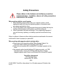
Safety Precautions
Please adhere to the hardware and software precautions
mentioned below. In addition, observe all safety precautions
mentioned in this manual.
When working with the overall system
1. Before handling components inside your computer system, exit all
applications and shut down the operating system in accordance with
procedures applicable to them.
2. Turn off the power to the computer and disconnect all cables that may be
feeding electrical power to the system you will be working on.
3. Wear a grounded, anti-static wrist-strap. This is especially important if
you are removing, replacing, or installing a printed circuit board of any
kind.
Failure to adhere to these and other safety precautions mentioned in the manual
could result in harm to property or personnel!
When working with magneto-optical cartridge disks
• Please refer to the Appendix entitled “Mass Storage Options” for
important details covering the handling of M-O disks!
• Never boot your system with a writable M-O cartridge inserted into the
drive!
• Use magneto-optical media that has 512 bytes per sector, not 1024
bytes per sector, and use the AFDisk software utility to format
magneto-optical media. Never use Windows 95 to format M-O media!
Triton Elics Internatonal
125 Westridge Drive
Watsonville, CA 95076
USA
© 1991-2004 Triton Elics International, Inc. All rights reserved. Printed in the
U.S.A.
SOFTWARE LICENSE AGREEMENT
By opening this package, you agree to be
bound by the terms of this Agreement,
which include the software license and the
limited warranty. This Agreement applies to
you and any subsequent licensee of this
software program. If you do not accept or
agree to the terms of this Agreement, do
not open this sealed package. Promptly
return the unopened package to TRITON
ELICS for a refund. However, no refund or
replacement will be given if the sealed
envelope containing the SOFTWARE
Sentinel and Manual has been opened or if
any of the components of the product
(including the software sentinel) are
missing. Grant of license for the software
product and full title and ownership of the
hardware product shall not transfer to the
Buyer until the purchase price, plus any
interest or fees resulting from late payments or pre-arranged terms, has been
received in full by the Seller.
1. GRANT OF LICENSE: TRITON ELICS
grants you the right to use the enclosed
TRITON ELICS software product in the
manner provided below.
YOU MAY:
•
•
•
Use one copy of the TRITON ELICS
software products identified above on
a single computer.
Make one (1) copy of the program in
machine-readable form solely for
backup purposes, provided that you
reproduce all proprietary notices.
Transfer the SOFTWARE and user
documentation on a permanent basis
provided you retain no copies and the
recipient agrees to the terms of this
Agreement.
YOU MAY NOT:
1. Reverse engineer, decompile, modify or
disassemble the SOFTWARE except to the
extent such foregoing restriction is
expressly prohibited by applicable law.
Remove any proprietary notices, labels, or
marks on the program, documentation, or
program disk.
2. UPGRADES. SOFTWARE and
documentation upgrades are provided free
of charge for one year from the date of
shipment. If the SOFTWARE is an
upgrade, you may use or transfer the
SOFTWARE only in conjunction with
upgraded product. You may use that
upgraded product only in accordance with
this License.
3. COPYRIGHT. The SOFTWARE
(including any images, “applets,”
animations, video, audio, music, and text
incorporated into the SOFTWARE) is
owned by TRITON ELICS and is protected
by United States copyright laws and
international treaty provisions.
4. TECHNICAL SUPPORT. Technical
Support is available by phone, fax, modem,
Triton Elics bulletin board service or Internet free of charge during warranty period.
MARISAT charges are invoiced at cost
plus twenty percent.
5. EXPORT RESTRICTIONS. You agree
that neither you nor your customers
intends to or will, directly or indirectly,
export or transmit the SOFTWARE or
related documentation and technical data
to any country to which such export or
transmission is restricted by any applicable
U.S. regulation or statute, without the prior
written consent, if required, of the Bureau
of Export Administration of the U.S.
Department of Commerce, or such other
governmental entity as may have
jurisdiction over such export or
transmission.
LIMITED WARRANTY
TRITON ELICS warrants that (a) the
SOFTWARE will perform substantially in
accordance with the accompanying written
materials for a period of one (1) year from
the date of shipment and (b) any hardware
accompanying the SOFTWARE will be free
from defects in materials and workmanship
under normal use and service for a period
of one (1) year from date of shipment.
CUSTOMER REMEDIES. TRITON
ELICS’s entire liability and your exclusive
remedy shall be, at TRITON ELICS’s
option, repair or replacement of the
SOFTWARE or hardware that does not
meet TRITON ELICS’s Limited Warranty.
Warranty service is F.O.B. TRITON
ELICS’s Watsonville facility. All shipping
and insurance costs are paid by buyer. Onsite Customer Service and Warranty
Repair (including travel hours,
transportation, lodging and meals) may be
provided by TRITON ELICS, at its own
discretion, to Buyer at cost plus twenty
percent. However, actual labor hours to
provide this service or repair will be free of
charge to Buyer. This Limited Warranty is
void if failure of the SOFTWARE or
hardware has resulted from accident,
abuse, or misapplication. Any replacement
SOFTWARE or hardware will be warranted
for the remainder of the original warranty
period or thirty (30) days, whichever is
longer.
NO OTHER WARRANTIES. Except for the
above express limited warranties, TRITON
ELICS makes no warranties, expressed,
implied, statutory, or in any communication
with you, and TRITON ELICS specifically
disclaims any implied warranty of
merchantability or fitness for a particular
purpose. TRITON ELICS does not warrant
that the operation of the program will be
uninterrupted or error free. Some
states/jurisdictions do not allow the
exclusion of implied warranties, so the
above exclusions may not apply to you.
This limited warranty gives you specific
legal rights. You may have others, which
vary from state/jurisdiction to
state/jurisdiction.
NO LIABILITY FOR CONSEQUENTIAL
DAMAGES. To the maximum extent
permitted by applicable law, in no event
shall TRITON ELICS be liable for any
damages whatsoever (including, without
limitation, damages for loss of business
profits, business interruption, loss of
business information, or any other
pecuniary loss) arising out of the use of or
inability to use this TRITON ELICS
product, even if TRITON ELICS has been
advised of the possibility of such damages.
Because some states/ jurisdictions do not
allow the exclusion or limitation of liability
for consequential or incidental damages,
the above limitation may not apply to you.
U.S. GOVERNMENT RESTRICTED
RIGHTS. The SOFTWARE and
documentation are provided with
RESTRICTED RIGHTS. Use, duplication,
or disclosure by the Government is subject
to restrictions as set forth in subparagraph
(c) (1) and (ii) of the Rights in Technical
Data and Computer Software clause at
DFARS 252.227-7013 or subparagraphs
(c) (1) and (2) of the Commercial Computer
Software—Restricted Rights at 48 CFR
52.227-19, as applicable. Manufacturer is
Triton Elics International, Inc., 125
Westridge Drive, Watsonville, CA 95076. If
you acquired this product in the United
States, this Agreement is governed by the
laws of California. If this product was
acquired outside the United States, then
local law may apply.
TRITON ELICS INTERNATIONAL
SOFTWARE LICENSE AGREEMENT
AND LIMITED WARRANTY
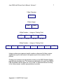
Preface Using This Manual
This book is the second part of a two-part set from Triton Elics International, Inc.:
Isis User’s Manual, Volume 2. It contains supplementary information, such as
file format structure, navigation templates, and other infrequently accessed Isis
information. Isis User’s Manual, Volume 1, contains most of the most frequently
accessed functions and information relevant to the software. Isis User’s Manual,
Volume 2, complements Volume 1.
Throughout this manual, warnings, hints and important statements are separated
from the text, italicized and denoted by the following symbols.
Skills You’ll Need to Know Before Using Isis
To use Isis, you should know basic Windows concepts, such as working with
icons on the Windows desktop. You can find this information in the Microsoft online Help system built into the Windows systems.
Finally, you should already be comfortable using the basics of Isis before delving
into Volume 2.
APPENDIX A Q-MIPS FILE FORMAT
1
A.1 GENERAL DESCRIPTION
1
A.2 HEADER AND FOOTER DATA
1
A.3 IMAGERY DATA
2
A.3.1 Eight-Bit Data
2
A.3.2 Sixteen-Bit Data
2
A.4 BINARY DATA REPRESENTATION
5
APPENDIX B ISIS BAC AND GAC FILE FORMATS
23
B.1 BAC FILE FORMAT
23
B.2 GAC FILE FORMAT
24
APPENDIX C MASS STORAGE OPTIONS
25
C.1 SCSI BUS CONFIGURATION
25
C2 USING EXABYTE TAPE DRIVES WITH ISIS
26
C3 USING THE SEG-Y FORMAT ON EXABYTE TAPE
28
C4 USING MAGNETO-OPTICAL DRIVES WITH ISIS
29
C.4.1 Different Sector Sizes, Different Purposes
29
C.4.2 Typical HP Cartridge Types
30
C.4.3.1 Backing Up Your M-O Data Before Reformatting
31
C.4.3.2 Formatting the M-O after Backing up Your M-O's Data
32
C.4.3.3 Restoring Your Backed Up Data after Reformatting
34
C.4.3.4 Restarting Windows 95 after Restoring Your M-O's Data 35
APPENDIX D SERIAL INTERFACES
36
D.1 CONNECTION
36
D.2 RECEIVE DATA FORMAT
37
D.3 TEMPLATE CONSTRUCTION
38
D.3.1 Example of Template Construction
40
D.3.2 Values Allowed Over Serial Interfaces and Stored by Isis
41
D.3.2.1 Examples of Pattern Matching
46
D.3.2.2 Examples of Character Alignment
47
D.3.3 Performing Math on Template Tokens
47
D.3.4 Template Instructions That Do Not Evaluate to a Number
49
D.4 SPECIAL READY-MADE TEMPLATES THAT ISIS CAN USE
D.4.1 How Isis Works with NMEA0183 Strings
50
51
D.4.1.1 How Isis Deals With Heading Issues in NMEA0183
Strings
52
D.4.1.2 How Isis Deals With Time Issues in NMEA0183 Strings 52
D.4.1.3 Real-Time Kinematic
D.4.2 Disabling ASCII Reports Produced by NMEA Packets
54
55
D.5 SPECIAL SERIAL RECEIVE STRINGS
55
D.6 TRANSMIT DATA FORMAT
58
D.7 LOGGING AND TRANSMITTING TO A SERIAL PORT
60
APPENDIX E USING THE TARGET UTILITY
61
E.1 RUNNING TARGET
61
E.2 TARGET'S FILE MENU
62
E.2.1 Find
66
E.2.2 Print ASCII Report
69
E.3 TARGET'S EDIT MENU
71
E.4 CONTACT LOGGING
76
E.4.1 Contact Information
76
E.4.2 Contact Mensuration
78
E.5 THE ENHANCE FUNCTION
81
E.6 TARGET'S WINDOW MENU
93
E.6.1 Tile, Cascade, Arrange Icons, Close All
94
E.6.2 Reduce Image and Expand Image
94
E.6.3 Threshold
96
E.6.4 Pan Left, Right, Up or Down
96
E.7 FORMAT OF TGT AND CON FILES
96
E.7.1 WPOINT: A Structure for Bridging Back to 16-Bit Systems
97
E.7.2 CINFO: Channel Information Header Structure
97
E.7.3 The Image Structure
102
E.7.4 Telemetry Structure
102
APPENDIX F WORKING WITH SIGNAL INTERFACES
105
F.1 SIGNAL INTERFACE UNIT 5 (SIU5)
105
F.2 SIU4 AND SIU4-2 ANALOG INTERFACE
106
F.2.1 Mechanical Description
107
F.2.2 Theory of Operation
109
F.2.3 System Tests Using the SIU4-2
111
APPENDIX G HOW ISIS PROCESSES CTD DATA
114
G.1 OVERVIEW
114
G.2 HOW ISIS TREATS SEABIRD CTD DATA
115
G.3 HOW ISIS TREATS FALMOUTH SCIENTIFIC CTD DATA
117
APPENDIX H USING A SEATEX MRU WITH ISIS
120
H.1 SETTING UP THE MRU
120
H.2 SETTING UP ISIS TO WORK WITH THE MRU
120
H.3 SAVING MRU DATA IN ISIS
120
H.4 IF THE MRU HAS A ONE-WAY SERIAL CONNECTION
123
APPENDIX I WORKING WITH SPECIFIC SONARS
124
I.1 EDGETECH DF1000 DIGITAL SONARS
127
I.1.1 Summary Description of an EdgeTech ACI Board
130
I.1.2 EdgeTech DF1000 Usage Notes
130
I.2 KLEIN ANALOG SONAR SYSTEM
131
I.3 KLEIN DIGITAL SONAR SYSTEM 2000
132
I.3.1 Hardware Setup
I.4 KLEIN DIGITAL SONAR SYSTEM 3000
132
133
I.4.1 Starting the Klein 3000 TPU
133
I.4.2 Configuring Isis for Klein 3000
133
1.4.2.1 'More Options' in Isis Server for Klein 3000 dialog box
I.5 KLEIN DIGITAL SONAR SYSTEM 5000
135
138
I.5.1 Starting the Klein 5000 TPU
138
I.5.2 Configuring Isis for Klein 5000
138
I.5.2.1 'More Options' in Isis Server for Klein 5000 dialog box
141
I.5.2.1.1 Log Data in Isis Panel
142
I.5.2.1.2 Miscellaneous Fields in 'More Options'
144
I.5.2.2 Some Guidelines for Speed, Range and Resolution
144
I.5.2.3 'Advanced Setup and Diagnostics' in Server for Klein5000144
I.5.2.3.1 Advanced Settings
145
I.5.2.3.2 Compute Depth from Voltage Panel
147
I.5.2.3.3 Diagnostics Panel
147
I.6 RESON SEABAT 81XX SONAR
147
I.7 SIMRAD 992 SONAR
157
June 2004 Isis® Sonar User's Manual, Volume 2
1
Appendix A Q-MIPS File Format
Isis and VISTA support a number of file formats: Q-MIPS, BAC, GAC, and XTF.
Each has distinct advantages. This appendix explains the structure and use of
the Q-MIPS format.
A.1 General Description
The Q-MIPS file format is perhaps the mostly widely known and used file format
for VIS_TA and other applications capable of displaying sidescan data imagery.
Q-MIPS-style data files are stored in binary format. Each data file consists of a
1024-byte file header followed by ping records. Each ping record consists of a
number of imagery channels followed by a 256-byte footer record.
The following format description is current for Q-MIPS version 6.69,
Q-MIPS/DSP version 1.16 and Isis . Both Isis and TrakMap use this same data
format. Q-MIPS and Q-MIPS/DSP are limited to four sonar channels and eight
imagery channels at 1024 pixels per channel (four raw, four corrected).
Table A-5 on page 9 and Table A-6 on page 16 describe each field in the header
and footer structures respectively. For specific C-language header and footer
structures used by Q-MIPS (and Q-MIPS/DSP) and Isis, refer to UPDATES.DOC
and QMIPSFMT.H respectively. These files are included with every software
release.
A.2
Header and Footer Data
For Q-MIPS systems, you can set some of the values in the header and footer in
the configurable files called QMIPS.DAT and SONAR.DAT. Refer to Appendix A
of the Q-MIPS User’s Manual for descriptions of these files. Isis relies on setup
configurations saved in the binary ISIS.CFG file for many of these values. You
can change many of the startup defaults loaded from the QMIPS.DAT,
SONARS.DAT and ISIS.CFG files without quitting and re-starting the Q-MIPS or
Isis program. Generally, display-related parameters can be changed on-the-fly
during collection. The current destination file must be closed before changing
most acquisition- and storage-related parameters from the menus.
Appendix A: Q-MIPS File Format
June 2004 Isis® Sonar User's Manual, Volume 2
2
Many other values are controlled by strings received over RS-232 serial
interfaces from the navigation system and/or any serial device. Refer to Appendix
E of the Q-MIPS User’s Manual or ‘Serial Interfaces’ (Appendix D) of this
manual for descriptions of the values that can be set in this manner. Navigation
telemetry values are replicated in their respective fields from ping to ping until a
new navigation string is received at the serial port. Then the values present in the
string are used to update the appropriate fields in the footer. If desired, the
Q-MIPS or Isis system time can be synchronized to the time indicated in the
telemetry string.
All binary data are stored according to the Intel representation scheme. This is an
important distinction if you plan to read or write Q-MIPS-style data using
Motorola-based, MIPS-based, or SPARC-based platforms.
A.3 Imagery Data
Regardless of how many samples are collected per channel per ping, the data
are decimated (or replicated) to be stored at 1024 pixels per channel per ping by
Q-MIPS or the user-specified number of pings by Isis. For a discussion of
available decimation methods, refer to the description of the
ch1_sampleScheme field under the heading Channel 1 Sonar Parameters in
Table A-6 on page 16.
Isis can save both 8-bit and 16-bit data in Q-MIPS format.
A.3.1 Eight-Bit Data
Each sample is an unsigned 8-bit value with a range of 0-255. Assuming
that the DSP card in Isis still has a factory jumper-setting configuration, the
input range is 5 volts. During the conversion from 16-bit to 8-bit, the sign bit
is omitted. So 0-255 represents a voltage range of 0 5 volts or 0 -5 volts
depending on the original input signal. Note that for side-scan, the important
quality to log is the magnitude of the signal from zero, not the actual
signed voltage.
A.3.2 Sixteen-Bit Data
The A/D converter on the Isis DSP card samples at 18 bits, with the 16 most
significant bits being available for storage. With 16 bits being saved, the
entire sample is logged. Each sample is a signed value.
Appendix A: Q-MIPS File Format
June 2004 Isis® Sonar User's Manual, Volume 2
3
16 bits represent -32768 to +32767. This corresponds to an input voltage
range of -5 to +5 volts. To convert a sample from the Q-MIPS file, use the
following formula:
volts = (sample / 32768) x 5
Equation A-1. Formula for converting a Q-MIPS sample to 16-bit format
Note that the actual range is actually -5 volts to +4.9998 volts.
Each pixel of imagery will require either one or two bytes of disk storage
depending on whether the data are saved at 8 or 16 bits per pixel. The
number of bits per pixel is specified for Q-MIPS in the QMIPS.DAT file and
for Isis using the Record Setup command.
Isis and Q-MIPS can store imagery in any combination of raw and corrected
for each of up to four analog channels. A corrected channel has had the
water column removed and has been slant-range corrected so that the
displayed waterfall record approximates a “map-view” of the data.
If both raw and corrected data are saved by Isis or Q-MIPS, 1024 raw pixels
are saved followed by 1024 corrected pixels for each channel. All specified
types for channel 1 (raw and/or corrected) are saved first. Then all types for
channel 2 and so on. The complete order for up to the Q-MIPS maximum of
eight imagery channels is shown below. Remember, when a channel is not
present or a data type (raw or corrected) is not to be saved, it is omitted.
That is, no padding is done. Fewer imagery channels results in fewer bytes
stored per ping.
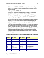
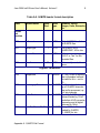
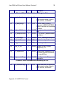
Table A-1. Relationship in Q-MIPS of channel to data type to location
Channel
Data Type
Read or Write
Location
CH1
RAW
Write only
Port
CH1
CORRECTED
Write or Read
Port
CH2
RAW
Write only
Starboard
CH2
CORRECTED
Write or Read
Starboard
CH3
RAW
Write only
Port or Subbottom
CH3
CORRECTED
Write or Read
Port or Subbottom
CH4
RAW
Write only
Starboard or Subbottom
Appendix A: Q-MIPS File Format
June 2004 Isis® Sonar User's Manual, Volume 2
CH4
CORRECTED
Write or Read
4
Starboard or Subbottom
Port channels are stored in pixel order (reverse chronological order) from far
range to nadir and starboard channels are stored from nadir to far range
(chronological order). This convention matches the left-to-right orientation for the
waterfall display on the Q-MIPS high-resolution imagery display. The ping
imagery data are followed by the footer for each ping.
Subbottom pings are normally received asynchronously with respect to side-scan
pings, downsampled differently, and stored with the nearest side-scan ping. A
subbottom channel is termed the asynchronous channel and must be received
on the last (highest number) channel present. The asynchronous ping rate is
generally slower than the side-scan ping rate so the data are replicated ping-byping until a new asynchronous ping is received.
When computing the size of Q-MIPS format files to estimate survey storage
media requirements or throughput rates, use the equations shown in
Equation A-2 on page 4 and Equation A-3 on page 4:
BPP = NIC x PPC x (BPX/8) + PFS in bytes
Equation A-2. Calculating bytes per ping
File Size = 1024 + (NP x BPP) in bytes
Equation A-3. Calculating file size using bytes per ping
where, in Equation A-3, the meaning of the variables are shown in:Table A-2
.
Table A-2. Variables for calculating bytes per ping
BPP
=
Bytes per ping
NIC
=
imagery channels being saved (raw and corrected)
NP
=
number of pings stored in file
PPC
=
pixels per channel per ping (always 1024 for Q-MIPS)
PFS
=
ping footer size = 256
BPX
=
bits per pixel (user-defined as 8 or 16)
Appendix A: Q-MIPS File Format
June 2004 Isis® Sonar User's Manual, Volume 2
5
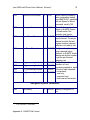
For example, a data file written by Q-MIPS with 3 pings of raw and corrected
imagery for each of two sidescan channels at eight bits per pixel would be
configured as follows:
Table A-3. Sample configuration illustrating file size
Size of Data in Bytes
Description
[1024]
Q-MIPS Header
[1024] [1024] [1024]
[1024] [256]
Ping 1, Four channels, 1024 bytes each; Q-MIPS
footer
[1024] [1024] [1024]
[1024] [256]
Ping 2
[1024] [1024] [1024]
[1024] [256]
Ping 3
The amount of memory all the data would occupy is:
14080 bytes [(1024 x 13) + (256 x 3)]
A.4 Binary Data Representation
The Q-MIPS format header and footer structures are made up of fields in six
number representation schemes or types. For each type shown in Table A-4 on
page 6, the type definition from the C-language Q-MIPS source code is shown in
parentheses and the range of numbers that can be represented by that type is
shown in brackets.
Note: Q-MIPS and Isis will never store a 12-bit value in a 12-bit field. All sonar
values are stored as 8 or 16 bit.
Appendix A: Q-MIPS File Format
June 2004 Isis® Sonar User's Manual, Volume 2
6
Table A-4. Data representation types for Q-MIPS headers and footers
Data Types Type Definitions and Possible Range of Values
SHORT
signed, two’s complement integer two bytes INT format
[-32,768 to 32,767] or four bytes LONG [-2,147,483,648 to
2,147,483,647] format
USHORT
unsigned integer two bytes WORD format [0 to 65,535] or four
bytes DWORD format [0 to 4,294,967,296]
FLOAT
floating point number in IEEE single precision standard four-byte
format FLOAT format [10-38 to1038]
DOUBLE
IEEE double precision standard eight-byte DOUBLE format
[10-308 to 10 308]
CHAR
signed character one byte CHAR format [-128 to 127]; can be
interpreted by ASCII code or as an 8-bit signed integer
BYTE
unsigned character one byte BYTE format [0 to 255]; can be
interpreted by ASCII code or as an 8-bit unsigned integer
The exact byte and word ordering for each of these types and the IEEE floating
point formats are described below. Any unused fields are filled with zeros, that is,
each bit within the field will be a zero instead of a one. The integers will return the
value 0, the floating point numbers will return the value 0.0, and the characters
will return the value 0 or the null character \0, depending on how they are
interpreted. In Table A-5 on page 9 and Table A-6 on page 16, which describe
the complete header and footer formats, respectively, one column indicates the
type for each field.
The Q-MIPS format data are stored according to the Intel processor scheme for
representation of numbers in memory. This is described below. If a number is
represented by N bytes from most significant (MSB, Byte N-1) to least significant
(LSB, Byte 0), and N x 8 bits from bit N x 8 -1 (MSB) to bit 0 (LSB), the stored
bytes are found in the order described below. The bits within each byte are
always in order from most significant (bit 7) to least significant (bit 0). All Intel
80x86 chips are Little Endian.
Appendix A: Q-MIPS File Format
June 2004 Isis® Sonar User's Manual, Volume 2
7
1-Byte Character
Byte 0
7 0
2-Byte Integer
LSB
MSB
7 0
15 8
4-Byte Number — Integer or Floating Point
LSB
Byte 1
Byte 2
MSB
7 0
15 8
23 16
31 24
8-Byte Number — Integer or Floating Point
LSB
Byte 1
Byte 2
Byte 3
Byte 4
Byte 5
Byte 6
MSB
7 0
15 8
23 16
31 24
39 32
47 40
55 48
63 56
Integer numbers are organized exactly as above, where each bit has a unique
significance equal to two raised to the power equal to the number of the bit
position.
Floating point numbers are represented according to the IEEE Standard floating
point formats described next. The formats are described in bit order from MSB to
LSB. Remember that the bytes are “out of order” as described above according
to the Intel processor number representation convention.
Appendix A: Q-MIPS File Format
June 2004 Isis® Sonar User's Manual, Volume 2
8
4-Byte IEEE Floating Point Number
s
exponent
2-1 2-2
31
30 23
22
fraction
2-23
0
value = (-1)s x 1.fraction x 2exponent - 127
8-Byte IEEE Floating Point Number
s
exponent
2-1 2-2
63
62 52
51
fraction
2-52
0
value = (-1)s x 1.fraction x 2exponent - 1023
Table A-5 on page 9 and Table A-6 on page 16 specify the formats for the
Q-MIPS header and footer structures respectively. Character fields that contain
more than one byte are arrays of characters interpreted as strings of text such as
the name of the sonar or the software revision. In the Q-MIPS data format, only
characters are arranged in arrays. The different sizes (in bytes) of the integer and
float fields indicates their different precisions as described above. In order to
save space and save you some reading time, two footnote symbols have been
used to represent information common to many of the fields. The symbols are
defined below and appear at the bottom of each of the tables.
Single dagger: This field is for storage only and is not used in any
†
Q-MIPS or Isis calculations.
Asterisk: This field is set to the value received over the serial
*
navigation interface (specified in navigation template) or among telemetry
from various digital towfish. If a value is not received, the field remains zero.
Appendix A: Q-MIPS File Format
June 2004 Isis® Sonar User's Manual, Volume 2
9
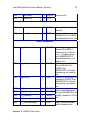
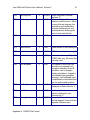
Table A-5. Q-MIPS header format description
Offset
Element Name
Bytes
Used
Value
Type
Remarks, Values,
Ranges, Units, Examples,
etc.
Format
and
Revision
0000
fileFormat
1
BYTE
50 for Q-MIPS files, 1 for
old S-MIPS files.
0001
systemType
1
BYTE
0 is Q-MIPS, 84 is
Q-MIPS/DSP, 202 is Isis.
0002
softwareRev
6
BYTE
Null-terminated string, e.g.
“6.61\0” or “Isis” for Isisrecorded files.
0008
spare1
20
BYTE
Not currently used, all
zeros.
Digitizer Parameters
0028
0030
0032
0034
sampleRate
2 USHORT [0...750], Q-MIPS digitizing
rate in ksamples/ second;
not valid for Isis — set to
20.
numImageryChannels
2 USHORT [1...8], number of channels;
up to 4 Q-MIPS channels,
raw and/or processed; up
to 4 Isis channels.
bitsPerPixel
2 USHORT [8 or 16], Q-MIPS analog
data are limited by 12-bit
resolution of A/D converter;
Isis analog and all digital
data can be 16-bit.
pixelsPerChannelPerPing 2 USHORT Always 1024 for files
created by Q-MIPS;
[0...65535] for Isis
Appendix A: Q-MIPS File Format
June 2004 Isis® Sonar User's Manual, Volume 2
0036
speedOfSoundInWater
4 FLOAT
0040
noLongerUsed
4 FLOAT
0044
asyncChannelNumber
0046
numSonarChannels
0048
ch1_processingAvailable
0050
ch2_processingAvailable
0052
ch3_processingAvailable
0054
ch4_processingAvailable
10
Sound velocity divided by
two in meters/sec loaded
from QMIPS.DAT; specified
with Isis Speed of Sound
command; usually 750.
Was initial sonar signal
divisor in Q-MIPS version
5.19 and earlier. Not
currently used, zeros.
2 USHORT [0...4] for Q-MIPS, 0 if no
async channel. The async
channel must be the last
(highest number) channel
collected; not used by Isis.
2 USHORT [1...4], number of analog
sonar channels being
digitized. In Q-MIPS, divide
sample rate by this number
to get the per-channel
sampling rate.
2 USHORT [0...3], indicates the
presence of, and
2 USHORT
processing applied to, each
2 USHORT of the four input channels:
2 USHORT 0: not present;
1: raw only;
2: corrected only;
3: both raw and corrected.
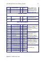
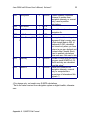
Navigation System Parameters
0056
navLatency1
1
Isis version 2.14 and later
Appendix A: Q-MIPS File Format
2 USHORT latency of navigation, in
ms.
June 2004 Isis® Sonar User's Manual, Volume 2
11
0058
navSystemName
100BYTE
Not currently used, all null
chars (0). Prior to version
6.00, set to
SERIAL_INPUT for serial
port nav. Could also be
QUILS II, SONARDYNE, or
NOTHING in older
versions.
Not currently used, all null
chars (0).
0158
projectionType
12 BYTE
0170
spheriodType
2 BYTE
0182
zone
2 USHORT Not used, all zeros (was
UTM zone).
0184
originLat
4 FLOAT
0188
originLong
4
0192
offsetLat
4
0196
offsetLong
4
0200
navUnits
2
Not currently used, all null
chars (0).
Origin of the local
coordinate system in
decimal degrees for
conversion from nav
system.
northings and eastings to
FLOAT
Latitude and Longitude; not
currently used, all zeros.
Offset of the local
FLOAT
coordinate system in
FLOAT
meters from origin; not
currently used; all zeros.
USHORT [0...3], units for nav data, 0:
meters, 1: feet, 2: yards, 3:
degrees (Latitude &
Longitude); feet and yards
are not currently used.
Site Parameters
0202
diveNumber
2 USHORT
0204
blockNumber
2 USHORT
0206
trackNumber
Appendix A: Q-MIPS File Format
All fields in this section are
2 USHORT currently not in use. They
ll t t 0
June 2004 Isis® Sonar User's Manual, Volume 2
0208
runNumber
0210
spare4[100]
12
2 USHORT are all set to 0.
100 BYTE
Annotation
0310
operatorAnnotation
100 BYTE
Not currently used, all null
chars (0).
0410
sonarName
40 BYTE
Sonar name from
SONARS.DAT for Q-MIPS;
“Isis Analog Server” for Isis.
Sonar Parameters
0450
triggerDirection
2
USHORT
0452
triggerMagnitude
4
USHORT
0456
triggerWidth
4
FLOAT
0460
ch1_frequency
2
USHORT
0462
ch2_frequency
2
USHORT
0464
ch3_frequency
2
USHORT
0466
ch4_frequency
2
USHORT
0468
ch1_horizBeamAngle
4
FLOAT
Appendix A: Q-MIPS File Format
Sonar trigger edge
direction for Q-MIPS, 1:
positive-going, 0: look for
level, -1: negative-going,
from SONARS.DAT or
Record Mode set-up; not
used by Isis.
Sonar trigger threshold in
A/D units (2.4mV) for
Q-MIPS, from
SONARS.DAT or Record
Mode set-up; not used by
Isis.
Duration of sonar trigger in
seconds for Q-MIPS, from
SONARS.DAT or Record
Mode set-up; not used by
Isis.
Sonar carrier frequency in
kHz from SONARS.DAT for
Q-MIPS; defaults to 100 for
Isis. *
Sonar 3dB narrow beam
width in degrees from
June 2004 Isis® Sonar User's Manual, Volume 2
0472
ch2_horizBeamAngle
4
FLOAT
0476
ch3_horizBeamAngle
4
FLOAT
0480
ch4_horizBeamAngle
4
FLOAT
13
width in degrees from
SONARS.DAT. Used in
mensuration and zoom
display correction; not
currently used by Isis.
Storage File Name
0484
thisFileName[45]
45 CHAR
Original path name of
current destination file.
0529
reserved2
1
Unused, the null character
(0).
CHAR
More Sonar Parameters
0530
ch1_halfWaveRectify
2
USHORT
0532
ch2_halfWaveRectify
2
USHORT
0534
ch3_halfWaveRectify
2
USHORT
0536
ch4_halfWaveRectify
2
USHORT
0538
ch1_tiltAngle
4
FLOAT
0542
ch2_tiltAngle
4
FLOAT
0546
ch3_tiltAngle
4
FLOAT
0550
ch4_tiltAngle
4
FLOAT
0554
ch1_beamWidth_3dB
4
FLOAT
0558
ch2_beamWidth_3dB
4
FLOAT
0562
ch3_beamWidth_3dB
4
FLOAT
0566
ch4_beamWidth_3dB
4
FLOAT
0570
ch1_realSampleRate
4
FLOAT
0574
ch2_realSampleRate
4
FLOAT
0578
ch3_realSampleRate
4
FLOAT
0582
ch4_realSampleRate
4
FLOAT
Appendix A: Q-MIPS File Format
Boolean, 1: channel is halfwave rectified, 0: this
channel is not rectified; set
to 0 for Isis.
Sonar transducer tilt angle
down from horizontal in
degrees, from
SONARS.DAT. Used in
beam angle compensation;
defaults to 30 for Isis
Sonar 3dB fan (vertical)
beam width in degrees from
SONARS.DAT. Used in
beam angle compensation;
defaults to 50 for Isis
Used in DSP only.
June 2004 Isis® Sonar User's Manual, Volume 2
14
Reserved Space
0586
spare5[438]
454
BYTE
Unused; all zeros.
†For storage only, not used in any Q-MIPS calculations.
*Set to the value received from navigation system or digital towfish; otherwise
zero.
Table A-6. Q-MIPS footer format description
Offset Element Name
Bytes Value
Used Type
Remarks, Values, Ranges,
Units, Examples, etc.
Date and Time
0000
0001
0002
0003
day
month
year
hour
1
1
1
1
0004
0005
minute
seconds
1
1
0006
thousandsSeconds
2
BYTE
BYTE
BYTE
BYTE
[1...31], day of the month.
[1...12], month of the year.
[0...99], year within the century.
[0...23], hour of the day, 24-hour
time.
BYTE
[0...59], minute within the hour.
BYTE
[0...59], seconds within the
minute.
USHORT [0...999], thousandths of
seconds. Time is kept by
Q-MIPS or Isis system clock
which can be synchronized to
the nav system time at each nav
fix (use AB in template).
Magnetometer Readings
0008
magX
4
0012
magY
4
0016
magZ
4
Appendix A: Q-MIPS File Format
FLOAT Magnetometer reading on x, y,
and z axes,
FLOAT units are not specified, the value
provided by
FLOAT the telemetry is stored with no
June 2004 Isis® Sonar User's Manual, Volume 2
15
conversion. †*
Ping Number, Ship Speed, Asynchronous Window Offset and Auxiliary
Storage
0020 pingNumber
4
USHORT Ping number starts at 1 in each
Q-MIPS file, 0 in each Isis file
and is incremented
automatically. Max = 4.29x10⁹.
0024 asyncByteOffset
2
USHORT When non-zero in Q-MIPS,
indicates the presence of a
unique asynchronous ping being
stored with this ping, when 0
indicates the most recent
asynchronous ping (if any) is
being replicated; not used by Isis
0026 shipSpeed
2
USHORT Speed of ship in knots multiplied
by 100. *
0028 auxVal1
4
FLOAT
0032 auxVal2
4
FLOAT Auxiliary telemetry values, user0036 auxVal3
4
FLOAT defined; displayed in Isis
0040 auxVal5
4
FLOAT Sensors box. †*
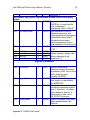
Digitizer Parameters
0044
auxAltitude
4
0048
triggerChannel
2
0050
altSource
2
0052
waterColumn
4
Appendix A: Q-MIPS File Format
FLOAT
Altitude in meters from
subbottom sensor if provided in
nav telemetry (DSP, Isis) or from
bottom detect on array
processor (Q-MIPS).
USHORT [1...4], Channel on which the
sonar trigger is to be detected,
from QMIPS.DAT.
USHORT Altitude source for water column
removal and correction for slant
range, 0: telemetry, 1-4: water
column detection channel, 5:
manual entry by user, set in
QMI_PS.DAT or by user.
USHORT Number of samples in the water
column as determined from
altSource.
June 2004 Isis® Sonar User's Manual, Volume 2
0056
triggerPeriod
4
0060
ch1_signalDivisor
2
16
USHORT Number of samples in the trigger
period determined from ping to
ping by Q-MIPS.
USHORT Chan 1 signal divisor •100. Set
to 1 for Isis. For Q-MIPS, raw,
signed, 12-bit, digitized sample
is divided by this and truncated
to 8 bits for display. The sign bit
is dropped. The default divisor of
8 fits the 11-bit unsigned value
into an unsigned 8-bit value.
Value of 1 leaves the samples
unchanged.
Towfish Telemetry
0062
telemFishDepth
4
0066
telemFishHeading
4
0070
telemFishPitch
4
0074
telemFishRoll
4
0078
telemFishAlt
4
0082
telemSbotAlt
4
0086
telemSpeedLog
4
0090
soundVelocity
2
Appendix A: Q-MIPS File Format
FLOAT
Depth of sonar source below sea
level in meters. *
FLOAT Magnetic heading of fish in
degrees. *
FLOAT Fish pitch in degrees, positive
nose up. *
FLOAT Fish roll in degrees, positive is
defined as starboard down. *
FLOAT Fish altitude above the sea floor
in meters, from navigation
telemetry or manual entry, takes
precedence over auxAltitude. In
Isis this is the tracked altitude. *
FLOAT Subbottom sensor altitude above
the sea floor in meters. Not used
by Isis. *
FLOAT Vehicle speed in meters per
second from electromotive
impeller speed log. †*
USHORT One-way sound velocity
multiplied by 30. Not used by
Isis. †*
June 2004 Isis® Sonar User's Manual, Volume 2
17
Channel 1 Sonar Parameters and Sampling Rate
0092
ch1_floatRawRange
4
0096
ch1_delayRange
4
0100
ch1_bandWidth
2
0102
ch1_sampleScheme
2
0104
ch1_rawRange
2
0106
0107
ch1_initialGain
reservedForFloatSa
mp
ch1_gain
1
2
0108
1
Appendix A: Q-MIPS File Format
FLOAT
Higher resolution raw maximum
slant range in meters. Used in
DSP and Isis; not Q-MIPS.
FLOAT Channel delay in meters,
entered in Q-MIPS DIGITIZER
menu in seconds and converted
to meters. Not used in Isis.
USHORT Sonar channel bandwidth in kHz.
Not used in Isis. *
USHORT [1...5] For storage, digitized
samples are decimated to 1024
samples per channel per ping
using one of five methods
defined as 1: average, 2:
maximum, 3: minimum, 4: rms,
or 5: none (meaning the first
sample in the group to be
downsampled is taken). The
method is defined for each
channel in QMIPS.DAT. Another
parameter, screen downsample
(0: skip, 1: average, 2:
maximum, 3: minimum) is not
stored but is also defined in
QMIPS.DAT and may be
changed from the keyboard. Set
to 2 in Isis.
USHORT Raw maximum slant range in
meters, stored even if only
processed imagery is saved,
zero if channel is not present.
On any asynchronous channel,
this holds the async range.
BYTE
Initial channel gain. †*
USHORT Sample rate in Hz used in DSP
only.
BYTE
Channel gain. †*
June 2004 Isis® Sonar User's Manual, Volume 2
0110
sampleRate
2
0112
ch1_correctedRang
e
2
18
USHORT Aggregate sample rate in kHz,
set by user in Q-MIPS record
mode setup. Not used in Isis.
USHORT Single-side range of corrected
channel in meters, zero if
corrected data are not saved. On
any asynchronous channel, this
holds the async delay in meters
multiplied by 100. Not currently
used in Isis.
Channel 2 Sonar Parameters
0114
ch2_floatRawRange
4
FLOAT
Higher resolution raw maximum
slant range in meters. Used in
DSP and Isis; not Q-MIPS.
0118
ch2_delayRange
4
FLOAT
Channel delay in meters,
entered in Q-MIPS DIGITIZER
menu in seconds and converted
to meters. Not used in Isis.
0122
ch2_bandWidth
2
USHORT Sonar channel bandwidth in
kHz. Not used in Isis. *
0124
ch2_sampleScheme
2
USHORT [1...5] See ch1_sampleScheme
description.
0126
ch2_rawRange
2
0128
ch2_initialGain
1
USHORT See ch1_rawRange description.
†
BYTE
Initial channel gain. †*
0129
ch2_gain
1
BYTE
0130
oceanTide
2
0132
ch2_signalDivisor
2
USHORT Altitude above Geoide (from
RTK)
USHORT Signal divisor multiplied by 100,
see under Digitizer Parameters
ch1_signalDivisor.
0134
ch2_correctedRange
2
Appendix A: Q-MIPS File Format
Channel gain. †*
USHORT See ch1_correctedRange
description
June 2004 Isis® Sonar User's Manual, Volume 2
19
description.
Channel 3 Sonar Parameters and Range to Fish
0136
ch3_floatRawRange
4
FLOAT
Higher resolution raw maximum
slant range in meters. Used in
DSP and Isis; not Q-MIPS.
0140
ch3_delayRange
4
FLOAT
0144
ch3_bandWidth
2
0146
ch3_sampleScheme
2
0148
ch3_rawRange
2
USHORT See ch1_rawRange description.
0150
ch3_initialGain
1
BYTE
Initial channel gain. †*
0151
ch3_gain
1
BYTE
Channel gain. †*
0152
range_to_fish
2
USHORT Distance to fish in meters
multiplied by 10.*
0154
ch3_signalDivisor
2
USHORT Signal divisor multiplied by 100,
see under Digitizer Parameters
ch1_signalDivisor.
0156
ch3_correctedRange
2
USHORT See ch1_correctedRange
description
Channel delay in meters,
entered in Q-MIPS DIGITIZER
menu in seconds and converted
to meters.
USHORT Sonar channel bandwidth in
kHz. *
USHORT [1...5] See ch1_sampleScheme
description.
Channel 4 Sonar Parameters and Bearing to Fish
0158
ch4_floatRawRange
Appendix A: Q-MIPS File Format
4
FLOAT
Higher resolution raw maximum
slant range in meters. Used in
DSP and Isis; not Q-MIPS.
June 2004 Isis® Sonar User's Manual, Volume 2
20
0162
ch4_delayRange
4
FLOAT
Channel delay in meters,
entered in Q-MIPS DIGITIZER
menu in seconds and converted
to meters. Not used in Isis.
0166
ch4_bandWidth
2
USHORT Sonar channel bandwidth in
kHz. Not used in Isis.*
0168
ch4_sampleScheme
2
USHORT [1...5] See ch1_sampleScheme
description.
0170
ch4_rawRange
2
USHORT See ch1_rawRange description.
0172
ch4_initialGain
1
BYTE
Initial channel gain. †*
0173
ch4_gain
1
BYTE
Channel gain. †*
0174
bearing_to_fish
2
USHORT Bearing to fish in degrees
multiplied by 100.*
0176
ch4_signalDivisor
2
USHORT Signal divisor multiplied by 100,
see under Digitizer Parameters
ch1_signalDivisor.
0178
ch4_correctedRange
2
USHORT See ch1_correctedRange
description.
Nav System Parameters and Additional Fish Telemetry
0180
waterTemperature
2
USHORT CTD water temperature
frequency times 100. †*
0184
eventNumber
4
SHORT
0186
auxVal6
4
0190
shipLatitude
8
Appendix A: Q-MIPS File Format
Last unique event or contact
number; corresponds to
contacts file in Q-MIPS.
FLOAT
Auxiliary telemetry value, userdefined; displayed in Isis
Sensors box. †*
DOUBLE Ship’s latitude in decimal
degrees. †*
June 2004 Isis® Sonar User's Manual, Volume 2
21
0198
shipLongitude
8
0206
navEasting
4
0210
navNorthing
4
DOUBLE Ship’s longitude in decimal
degrees. †*
FLOAT
Computed fish position in
meters if navUnits are m. When
the navUnits are degrees, the
navEasting and navNorthing
fields are combined into one
double-precision floating point
value to hold navLatitude.
FLOAT
0214
cableTension
4
FLOAT
0218
conductivity
4
FLOAT
0222
navFishHeading
4
FLOAT
For backward compatibility with
S-MIPS files only. All zeros. Not
currently used.
0226
navFishSpeed
4
FLOAT
0230
navShipGyro
4
FLOAT
Fish speed in knots from nav
telemetry or computed from
navigation telemetry N and E
velocities, used in imagery
display calculations. If speed is
not available from navigation
telemetry, navFishSpeed is set
to shipSpeed or calculated from
point-to-point towfish position.
Ship’s heading in degrees
displayed on status monitor. †*
0234
auxVal4
4
FLOAT
0238
navLongitude
8
Appendix A: Q-MIPS File Format
Cable tension in from serial port.
†*
CTD Conductivity frequency. †*
Auxiliary telemetry value, userdefined; displayed in Isis
Sensors box. †*
DOUBLE Computed fish position in
decimal degrees if navUnits are
degrees, otherwise zero.
June 2004 Isis® Sonar User's Manual, Volume 2
22
0246
fishLayback
2
0248
navFixHour
1
USHORT Towfish layback (horizontal
distance) in meters from
navigation telemetry or manual
entry, used in position
calculations.
BYTE
0249
navFixMinute
1
BYTE
0250
navFixSeconds
1
BYTE
0251
relativeBearingToFis
h
1
CHAR
0252
julianDay
2
0254
cableOut
2
Time of the most recent
navigation fix.
Bearing to towfish in integral
degrees off ship’s course, ship
to fish straight back is 000, to
starboard is -090; calculated
and stored only when you have
entered a non-zero layback and
a lateral offset (Veeder Root).
Used in position calculations
when non-zero. Not used in Isis.
USHORT Number of days since the first of
the year, since Q-MIPS v5.18.
Month and day are calculated
from this value.*
USHORT Cable out in meters from
navigation telemetry, manual
entry or computed as a
percentage of telemetered fish
layback. †
† For storage only, not used in any Q-MIPS calculations.
* Set to the value received from navigation system or digital towfish; otherwise
zero
Appendix A: Q-MIPS File Format
June 2004 Isis® Sonar User's Manual, Volume 2
23
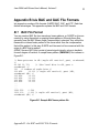
Appendix B Isis BAC and GAC File Formats
Isis supports a number of file formats: Q-MIPS, BAC, GAC, and XTF. Each has
distinct advantages. This appendix explains the BAC and GAC formats.
B.1
BAC File Format
You can create a BAC file from transducer beam patterns, or Q-MIPS or Isis can
create it by using theoretical or empirical beam patterns. Although these files
generally have the BAC (Beam Angle Compensation) extension, they reflect the
measured or inferred beam pattern of the sonar rather than the compensation
that will be applied. In this way, Q-MIPS and Isis need not be concerned with the
origin of a BAC that is applied.
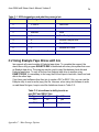
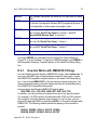
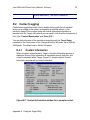
All BAC files are ASCII and consist of paired signal intensity values in decibels
for each degree off vertical. A sample beam pattern (SM28.BAC) file is shown in
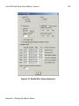
Figure B-1.
/* Beam patterns in dB (angle off vertical, port, starboard)
*/
22.183 21.703
/* (Max level bias in dB, port &
starboard) */
131
/* number of angle bins */
012.858
12.166 /* angle off vertical, port (dB),
starboard (dB) */
112.858
12.166
212.858
12.166
312.858
12.166
412.858
12.166
...
...
...
1290.552
0.599
1300.000
0.000 /* angle off vertical, port (dB),
starboard (dB) */
Figure B-1. Sample BAC beam pattern file
Appendix B: Isis BAC and GAC File Formats
June 2004 Isis® Sonar User's Manual, Volume 2
B.2
24
GAC File Format
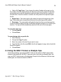
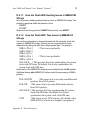
Q-MIPS or Isis can create Grazing Angle Compensation files, either theoretically
or empirically. The GAC files are ASCII and consist of paired multiplicative
corrections for each degree of grazing angle from 0 (far range) to 45. A sample
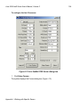
GAC file (SM28.GAC) is shown in Figure B-2.
/* Grazing Angle Corrections */
46
/* number of angle bins */
01.858697
1.253826 /* grazing angle, port, starboard
corrections */
11.809185
1.233621
21.759672
1.213416
31.710160
1.193211
41.660647
1.173006
...
...
...
441.000000 1.000000
451.000000 1.000000 /* grazing angle, port, starboard
corrections */
Figure B-2. Sample GAC beam pattern file
Appendix B: Isis BAC and GAC File Formats
June 2004 Isis® Sonar User's Manual, Volume 2
25
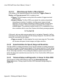
Appendix C Mass Storage Options
Isis does not restrict you to recording your data on just one kind of medium. You can record to
mass storage devices such a fixed hard disk, removable tape, or removable magneto-optical
disk.
C.1 SCSI Bus Configuration
All Isis optional mass storage devices, which are internal, are SCSI devices and thus require
the use of the Isis SCSI adapter card. Each drive and its adapter card has a unique ID (0 to 7)
on the SCSI bus. SCSI devices are daisy-chained with internal devices connected to the
adapter’s internal connector; external devices are connected to the adapter’s external
connector on the Isis back panel.
Each end of the SCSI bus must be terminated. The Isis system is delivered with the hard drive
terminated at the internal end of the SCSI bus. If additional external devices are connected to
Isis, the last daisy-chained external device must be terminated. If no external devices are
connected, the adapter will automatically terminate itself. The SCSI bus should be terminated
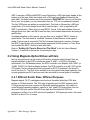
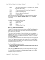
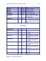
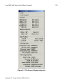
only at its extreme ends. Isis can access SCSI devices as shown in Table C-1.
Do not over-terminate the SCSI bus. Improper
termination can cause the SCSI adapter to fail!
Appendix C: Mass Storage Options
June 2004 Isis® Sonar User's Manual, Volume 2
26
Table C-1. SCSI designations and what they mean to Isis
SCSI ID
Drive Designation
Device
0
C: and D:
Hard drive
1
reserved
none
2
reserved
none
3
Y:
First Exabyte drive
4
Z:
Second Exabyte drive
5
E:
First M-O drive
6
F:
Second M-O drive
7
reserved for controller
none
C.2 Using Exabyte Tape Drives with Isis
Isis supports all current models of Exabyte tape drives. To complete the support, the
stand-alone utility program EXABYTE.EXE is distributed with every Isis system that uses
an Exabyte tape drive. The program may be used to copy files between hard disk and
Exabyte tape drives. To copy a file from one Exabyte tape drive to another using
EXABYTE.EXE, it is necessary to first copy the file from tape to hard disk, then from hard
disk to the other tape.
If you have used software other than Isis to create a DAT or SEG-Y file, you can use the
Exabyte utility to read or write (copy) the file. However, when using Isis software to write
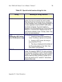
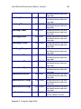
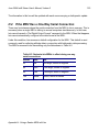
or read these file types, keep in mind the limitations shown in Table C-2:
Table C-2. Isis software’s ability to write or
read DAT and SEG-Y files
File Type
Write It?
Read It?
.DAT
no
yes
.SEG
Appendix C: Mass Storage Options
yes
yes
June 2004 Isis® Sonar User's Manual, Volume 2
27
Note:
EXABYTE.EXE only recognizes standard DOS file structures. The utility
cannot be used to work with SEG-Y format tapes written by Isis. Refer to ‘Using the
SEG-Y Format on Exabyte Tape’ on page 32 for a discussion on how Isis interprets
the SEG-Y format.
You can also use EXABYTE.EXE to archive disk files to tape.
Tape motion is controlled in Isis via the Playback and Record mode Tape Control dialog
boxes. Refer to Figure 3-7 on page 39 in the Isis User’s Manual, Volume 1, for a
discussion of the Tape Control dialog boxes.
To start the Exabyte program
• Type EXABYTE Y: [Enter], or type EXABYTE Z: [Enter]
The following options are available through EXABYTE.EXE:
3. Directory: This option displays the contents of a tape. It will also display the
names of files copied to it with the Exabyte program.
In Isis, the Directory option only recognizes the file format that the Exabyte
program writes to the tape during record mode or the Exabyte program’s Copy
file option.
4. Copy File: You use Copy file to copy files to or from an Exabyte drive. Choose
either Copy To and Copy From.
• Option #1: Copy To: With this option, you can copy a single file or multiple files.
The file will be copied to the tape at the current tape position. Any files that reside on
the tape after the current position will probably be lost.For example, to copy all DAT
Q-MIPS files in the D:\QMIPS directory to an Exabyte tape, use the Copy to option
and specify D:\QMIPS\*.DAT as the source name to copy.
Appendix C: Mass Storage Options
June 2004 Isis® Sonar User's Manual, Volume 2
28
• Option #2: Copy From: If you choose this option, Exabyte will prompt you for
the number of the file (obtained from the Directory option) to be copied to hard disk,
and prompt you to enter the destination path and name of the file to be created on
the hard drive. Once the number is entered, the utility rewinds the tape and copies
the file.
3. Rewind tape: The rewind option will position the tape at the beginning of the
tape. If the erase option is specified at this point, the entire tape will be erased.
4. Erase tape: The erase option will erase the tape from the current tape position
to the end. Before erasing the tape, the Exabyte program will ask you to confirm your
intention. The tape will be automatically rewound at the end of the erase pass.
To erase the entire tape
• Choose Rewind.
•
Choose Erase.
To erase the tape after a specific file
1. Get a Directory.
2. Choose the Copy To option.
3. Enter the number of the last file you want to save.
4. Copy that file to the file name NULL (the file will appear to copy, but no hard disk
file will be created).
5. Choose Erase.
C.3 Using the SEG-Y Format on Exabyte Tape
Technically speaking, only genuine SEG-Y data can be written to SEG-Y tape media.
However, few people still use SEG-Y tape any more; most now use Exabyte tape. Isis
uses true SEG-Y data format on Exabyte tape. Except for the difference in the two tape
media types, our format is indeed true SEG-Y.
Appendix C: Mass Storage Options
June 2004 Isis® Sonar User's Manual, Volume 2
29
SEG-Y requires a 3200-byte EBCDIC record followed by a 400-byte binary header at the
beginning of the tape. Each trace starts with a 240-byte trace header followed by the
trace data. The three headers are all documented in SEGYFMT.H. If you do not find this
file on your Isis system, you can download it from our FTP site (no password needed).
The first 3200 bytes are written as a single block. This block is followed by a 400-byte
single block. (You must change block size to read the tape — this is required by the
SEG-Y specification.) When trying to read SEG-Y format, if the read software does not
change block size, then it will fail to read the data. Isis includes these blocks according to
specification.
As stated elsewhere in this manual, you can also use a “modified” SEG-Y format on
optical disks. The disk format is “modified” because of the difference in the types of
media: Tape access is sequential (“flat file”) whereas disk access is random. However,
the SEG-Y specification only accommodates sequential, flat-file access, so Triton Elics
has modified the SEG-Y format to work with disks.
Refer to ‘Setting Up Tape to Record or Play Back’ in the Isis User’s Manual,
Volume 1, to see how to set up Isis for recording on tape.
C.4 Using Magneto-Optical Drives with Isis
Isis can recognize and use up to two multi-function magneto-optical drives if they are
logically attached to the SCSI controller as drives E: and F: in a DOS or Windows
environment. For 486-based systems, the SCSI controller is an Adaptec AHA 1542C (or
1542B, 1542CF); for Pentium-based systems, the SCSI controller is an AIC-7870 on the
CPU board. The two drives should be configured for SCSI ID numbers 5 (for drive E:)
and 6 (for drive F:). The M-O drives installed in an Isis system have large capacities (one
or more gigabytes per M-O) and can read from and write to several types of cartridges.
C.4.1 Different Sector Sizes, Different Purposes
Magneto-optical (“M-O”) cartridges come low-level formatted with either 1024-byte
sectors or 512-byte sectors. The 1024 size is typically used for UNIX systems, while
512-byte sectors are more common for Microsoft operating systems. Isis, which run
under Microsoft operating systems, expects to “see” (read) 512-byte sectors. Isis can
also read 1024-byte sectors if the M-O was high-level formatted for DOS, but
performance suffers: For an M-O low-level formatted at 1024-bytes per sector, Isis reads
the M-O at about 10% of normal.
Appendix C: Mass Storage Options
June 2004 Isis® Sonar User's Manual, Volume 2
30
Whenever you are using an application such as Isis on Microsoft’s
Windows 95, Windows NT, Windows 3.11 or DOS, use cartridges low-level
formatted for 512-bytes/ sector. Never use 1024 bytes/sector M-O
cartridges with Isis!
Note:
An M-O cartridge’s capacity is independent of its low-level bytes per sector
format; one cannot deduce the bytes per sector from the M-O’s capacity. The only way to
know the bytes per sector of a given M-O is to inspect the labeling on the cartridge and
read how many bytes per sector the manufacturer says it has.
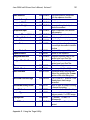
C.4.2 Typical HP Cartridge Types
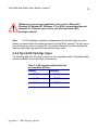
The following table lists HP model numbers for Isis-compatible media. Compatible media
are also available from several other manufacturers.
Table C-3. HP magneto-optical media that
are compatible with Isis
Capacity
Rewritable
600 MB
92279A
1.2 GB
92279T
2.4 GB
92279F
Appendix C: Mass Storage Options
June 2004 Isis® Sonar User's Manual, Volume 2
31
Triton Elics recommends you use HP media cartridges because they are very
reliable and have a 30-year warranty.
Media cartridges with 512-byte sectors written by other compatible magneto-optical
drives (for example, Sony and other ISO-standard drives) can also be read by the HP
multi-function drives.
C.4.3 High-Level Formatting Considerations
In general, you need one hard disk partition per side of the M-O. You accomplish this
using AFDISK. In addition to knowing the low-level format of an M-O cartridge, such as
the number of bytes (typical 512 or 1024) per sector, you need to take into account the
M-O cartridge’s high-level format that will be used with Isis. An M-O cartridge that will be
used with Isis must be high-level formatted with one DOS hard disk partition.
To high-level format an M-O cartridge, refer to C.4.3.2 (‘Formatting the M-O after Backing
up Your M-O’s Data’) on page 32.
If you believe your data disk already has been high-level formatted with what AFDISK
calls Standard Hard Disk Format (i.e., the DOS high-level format), then exit Windows and
re-start Windows 95 with the WIN/D:F command. You should now be able to read the
1024 Byte/sector M-O disk, albeit slowly.
C.4.3.1 Backing Up Your M-O Data Before Reformatting
Because formatting destroys any data existing on the cartridge, you will want to back up
your M-O data before formatting.
To back up your data from the M-O
1. With the M-O cartridge in Drive E:, exit Windows 95. (When the message comes
up that allows you to go to DOS, close Windows completely and go to DOS — not
just the DOS shell).
2. In DOS, use COPY or XCOPY to copy your files from your M-O to your D: drive.
Appendix C: Mass Storage Options
June 2004 Isis® Sonar User's Manual, Volume 2
32
C.4.3.2 Formatting the M-O after Backing up Your M-O’s Data
As noted above, HP cartridges come pre-formatted with 512-byte (or 1024-byte) sectors,
but high-level formatting must be completed and a DOS-style partition must be created
on these cartridges before they can be used.
If your data is backed up as indicated in the previous subsection, you now are ready to
reformat your M-O with a high-level format suitable for DOS and Windows. You use the
AFDISK utility to do this to both sides. This will erase any data on the cartridge!
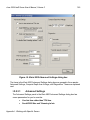
To high-level format side #1 of a magneto-optical cartridge
1. Exit Windows completely (don’t just shell out to DOS).
2. At the DOS prompt, go to the C:\ASPI directory, where AFDISK.EXE utility is
located.
3. Insert a new cartridge in the E: or F: drive.
4. Type AFDISK, and press [Enter] to run AFDISK.
5. In AFDISK, take the following steps to partition and label the cartridge.
a. Use the arrow keys to highlight the SCSI ID of the drive which holds the
cartridge to be partitioned. This will be 5 for drive E: or 6 for drive F:. Verify
that the model number of the SCSI device that you choose is C1716T. Once
the drive is highlighted, press [Enter] to select it. Do NOT select SCSI ID 0!
When formatting M-O cartridges, care must be taken not to erase the
hard drive. NEVER use the AFDISK.EXE to access SCSI ID 0!
If the media in the selected drive is unformatted, AFDISK displays a message:
This disk is unformatted.
--Press <Esc> to continue--
Appendix C: Mass Storage Options
June 2004 Isis® Sonar User's Manual, Volume 2
33
If this message does not appear, STOP! The cartridge may already
contain data. Formatting or creating a partition will delete any
previously saved data!
a. Press [Esc]. The system notifies you of the formatting options:
AFDISK allows users the option of a floppy format or a hard disk format for the medium
selected. Hit the [F1] key for more information on disk formats
--Press <Esc> to continue-b. Press [Esc] to display the formatting options.
c. Use the arrow keys to select Standard Hard Disk Format and press [Enter] to
select this option. AFDISK will display a message asking you to wait while the disk is
formatted. This will take about ten seconds.
• When the formatting is completed, logical drive information will be displayed
in the lower left corner of the display and a partition table for the cartridge will be
displayed in the upper right hand corner of the display.
d. Verify that no partitions exist (the partition table is empty).
•
If the partition table is not empty, you are attempting to partition a cartridge
side that has already been partitioned. STOP. The cartridge may contain
data that will be lost if you modify the partition table.
• If the partition table is empty, press the [Insert] key to create a partition.
e. Press [Enter] to accept the full capacity of one side of the cartridge as the
partition size.
f. Press [Enter] to create the partition.
g. Press [Esc] to quit AFDISK. AFDISK will ask you to re-start the computer by
pressing [Ctrl] [Alt] [Del]. Do this and wait for the system to go through its start-up
routine.
h. At the DOS prompt, type LABEL E: (or F:) to assign a volume label to this side of
the cartridge.
To high-level format side #2 of a magneto-optical cartridge
1. Eject the cartridge you just formatted.
2. Turn it over and insert it again.
3. Run AFDISK again from the DOS prompt.
Appendix C: Mass Storage Options
June 2004 Isis® Sonar User's Manual, Volume 2
34
4. Repeat steps 7 through 15 of the procedure, ‘To high-level format side #1 of a
magneto-optical cartridge’.
Partitioned cartridges, inserted into the HP drives, function as DOS logical drives. All
DOS and Q-MIPS commands function normally on rewritable cartridges. Write-once
cartridges, however, cannot be erased functionally once they have been written.
To partition a new MO using AFDISK.EXE with NT
1. Download a file from our FTP site called EBD_95.ZIP.
2. Unzip it to a floppy.
3. With the floppy in the drive, make the floppy bootable by typing this command
from any DOS or Win95 machine:
SYS C: A:
4. Shut down the NT machine that is equipped with the MO drive or drives.
5. Put the floppy in the NT machine, restart it, and allow the machine to reboot from
the floppy.
6. Put a new (never before formatted or partitioned) MO cartridge in your MO drive.
7. At the a:\ prompt, type AFDISK and press [Enter].
8. Select the MO drive you want to partition.
If your MO cartridge is new (unformatted), you will get the message, This disk is not
formatted If your MO cartridge is not new (has already been formatted/partitioned),
AFDISK will say it cannot proceed. Continue with ‘To high-level format side #1
of a magneto-optical cartridge’ on page 32.
C.4.3.3 Restoring Your Backed Up Data after Reformatting
Your reformatted M-O is now ready to receive the data you backed up.
Appendix C: Mass Storage Options
June 2004 Isis® Sonar User's Manual, Volume 2
35
To restore your backed up data to the newly formatted M-O
• Copy your files from the D: drive back to your newly formatted M-O cartridge on
E:
C.4.3.4 Restarting Windows 95 after Restoring Your M-O’s Data
If you have restored your data to your M-O, you are now ready to resume using it with
Windows 95.
To make Windows 95 see your M-O if it has 1024 bytes per sector
• Re-start Windows 95 by typing WIN/D:F.
This will permit Win 95 to recognize your low-level formatted M-O disk that has 1024
bytes/sector. As previously noted, reading the 1024 bytes/sector M-O will be slow
(about 10% normal).
Appendix C: Mass Storage Options
June 2004 Isis® Sonar User's Manual, Volume 2
36
Appendix D Serial Interfaces
As noted in Chapter 3, ‘Using the File Menu’, Isis User’s Manual, Volume 1,
Isis supports up to 16 serial com ports, many of which can be used to feed
navigation information to Isis from external devices that can transmit over serial
ports. You can manage the output of an external device’s transmission by writing
your own serial interface string and using it as a template for the device.
This appendix explains:
• the connections you need to hook up your serial input device to your Isis
system
• how the Isis software receives the data from the serial device
• what tokens can be used to make a serial interface template, and
• what a typical template looks like
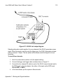
D.1
Connection
Serial (RS232) input to Isis is done through the 9-pin com connector(s) found on
the back panel of the Isis. The basic Isis system is equipped with a com1 port.
com2 is reserved for the trackball. Additional com ports are available as options.
The com ports are female IBM AT DB-9 serial connectors. Triton Elics ships
them with the pinouts shown in Table D-1. If your Nav system pinouts differ from
these defaults, you may want to write them in here.
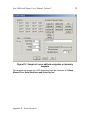
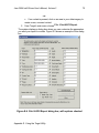
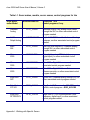
Table D-1. Isis pinouts for COM1 serial port
Isis uses these pins for these functions
Your Nav System uses
Pin 1 <---------------------- Carrier Detect ------------ _______________________
*Pin 2 <--------------------- Receive Data ------------- _______________________
*Pin 3 ----------------------- Transmit Data -----------> _______________________
Pin 4 ------------------------ Data Terminal Ready -> _______________________
*Pin 5 ----------------------- Ground --------------------- _______________________
Pin 6 <---------------------- Data Set Ready ---------- _______________________
Appendix D: Serial Interfaces
June 2004 Isis® Sonar User's Manual, Volume 2
37
Pin 7 ------------------------ Request To Send ------> _______________________
Pin 8 <---------------------- Clear To Send ------------ _______________________
Pin 9 <---------------------- Ring Indicator ------------ _______________________
*Only pins 2, 3, and 5 are needed for a complete interface. All other pins are
physically connected but not used by the Isis software.
Some serial communications devices use DB-25 connectors. These may be
connected to Isis with the installation of a DB-9 to DB-25 converter or similar
cable, which may be purchased at an electrical supply shop.
The serial cable should be connected to Isis with the power OFF.
D.2
Receive Data Format
Because Isis can connect to many different navigation or telemetry systems, a
generic user-definable method has been developed to allow easy integration of
new interfaces. Isis can accept and store a wide range of navigation and
telemetry information. Although both binary and ASCII data may be received over
a serial port, use of a user-defined navigation template requires serial data to be
received in ASCII.
Note: All values transmitted over the serial port must be separated (delimited)
by a non-numeric character. Numeric characters are included in the following set:
{0123456789.-}
Here’s what happens when Isis gets data from a serial interface:
1. Isis receives a single transmission string from the serial port. This
string is terminated with any character (or characters) having an ASCII
value of less than 14. This includes carriage return and line feed (CR,
LF).
2. Isis parses the serial transmission based on the alphanumeric
combination of characters.
3. Isis assigns each number in the string to the respective field
described by the Serial Template, described next.
Appendix D: Serial Interfaces
June 2004 Isis® Sonar User's Manual, Volume 2
D.3
38
Template Construction
For each com port and its associated serial device that will be communicating
with Isis, you can use a ready-made template or create your own to be used as
the interface.
To select or create a template in Isis
1. From the File menu, select Record Setup, then Serial Ports.
2. Choose a com port to be used with a given serial device you have
in mind.
3. Enable status by clicking in the Status box. A check mark will be
visible in the On box when status is enabled.
4. Either:
•
Refer to the buttons displaying ready-made “server” software
types (NMEA0183, TSS, Seatex MRU, SeaBat #1, SeaBat #2),
choose one to be your template, and choose OK.
or
• Create your own in the Navigation/Telemetry text box provided
and choose OK. (A sample user-defined template appears in
Figure D-1.)
Appendix D: Serial Interfaces
June 2004 Isis® Sonar User's Manual, Volume 2
Figure D-1. Sample of a user-defined navigation or telemetry
template
The template can accept up to 200 characters from the list shown in ‘Values
Allowed Over Serial Interfaces and Stored by Isis’.
Appendix D: Serial Interfaces
39
June 2004 Isis® Sonar User's Manual, Volume 2
D.3.1
40
Example of Template Construction
Say a simple data logger transmits data over a serial port at 2400 baud, 1
stop bit, 8 data bits and even parity. An example of a string transmitted over
such a serial port might be
4/20/90 17:31:22 NORTH 93285.35 EAST 319294.29,
H:344.0
Before Isis can use the above data, you need to set up a com port to
receive it. You do so in the Serial Port Setup dialog box (Figure D-1 in this
book). In this case, you would set the Baud Rate to 2400, Data Bits to 8,
Stop Bits to 1 and Parity to Even.
Second, create the serial navigation template. The example transmission
string previously mentioned shows that data is formatted by the data logger
in the following order:
day month year hour minute second north east heading
For this example, we will assume that the heading is “course made good,”
that the heading has been processed by the data logger, and that no other
heading is available. Consequently, the towfish will have to use that
heading. Also assume that Isis will synchronize its system time and date to
that of the data logger. This set of assumptions will enable Isis to correctly
return coordinates for imagery pixels when the cursor is moved around the
graphics display.
When you construct a template to match the data transmitted with the
template codes just described, the result would be a string in a tokenized
format:
DMYHISNEh
Isis interprets the tokenized DMYHISNEh string as follows:
D =
day
20
M =
month 4
Y =
year
90
H =
hour 17
I =
minute 31
S =
second 22
N =
northing
93285.35
E =
easting 319294.29
h =
towfish heading
344.0
Appendix D: Serial Interfaces
June 2004 Isis® Sonar User's Manual, Volume 2
41
All letters sent with the serial transmission will be ignored except for those
used to separate the individual values.
Note:
For date and time, Isis uses the NMEA0183 standard. See ‘How
Isis Works with NMEA0183 Strings’ in Volume 2
As soon as you put Isis in Record mode, Isis will begin monitoring the serial
ports for transmissions. To test the interface, use the COM Port Test option
in the Tools menu (see ‘Com Port Test’, Isis User’s Manual, Volume 1) or
choose Test in the Serial Port Setup dialog box. Both access methods lead
to the same com Port Test dialog box.
Template entries are CASE SENSITIVE (that is, upper or lower
case entries are treated as unique entries) and must not contain
any space characters. Values are decoded as METERS except
where noted. For Isis to interpret northings and eastings as feet,
the template entries must include an upper case F.
D.3.2 Values Allowed Over Serial Interfaces and
Stored by Isis
Isis has a wide range of user-defined tokens that you can use in your
templates. When some of the user-defined tokens are surrounded by
delimiters, the meaning of the token changes. Isis can use and store many
character tokens over a serial interface (Table D-2).
Note:
In Table D-2, some tokens are enclosed in delimiters. Delimited
tokens are distinct from non-delimited tokens. In the table, we have used
braces as delimiters, but we could have used parentheses or brackets — all
are valid; Isis treats them the same. Both types of tokens (delimited and
non-delimited) are explained in the table.
Table D-2. Delimited and non-delimited tokens used by Isis
Token
0
Meaning
(zero char) Fish depth in meters. (Manual depth overrides this
value.)
Appendix D: Serial Interfaces
June 2004 Isis® Sonar User's Manual, Volume 2
1
2
3
4
5
6
7
8
9
;
>
?
D
E
F
G
H
I
J
L
M
N
O
P
Q
42
Auxiliary Value 1
Auxiliary Value 2
Auxiliary Value 3
Auxiliary Value 4
Auxiliary Value 5
Auxiliary Value 6
Fish Altitude in (meters)
Fish Pitch (degrees)
Fish Roll (degrees)
Pressure temperature (CTD data)
Bearing to Fish (degrees). This is the same as the {bf} token.
Range to Fish (meters)
Day
Easting (or longitude if $ is included in the nav template) for the
fish position — see {lom} in this table.
Causes Northing and Easting to be converted from feet to meters
according to the equation (N|E) * (39.37/12.0)
Gyro (direction ship is pointing)
Hour
Minute
Julian day
Latency in seconds (age of the navigation at point when first
serial character received): “fix Late” (seconds to subtract from
transmitted time). This template character now accepts nav
latency in decimal form. Receive time in milliseconds, minus this
value, is posted in the XTF file’s NavMillisecond_Clock field.
Month
Northing (or latitude if $ is included in the nav template) for the
fish position — see {lam} in this table.
[capital “Oh”] Next event number to use (changing value forces
event). In Isis User’s Manual, Volume 1, refer to the sections
‘Mark Event’ on page 143, for setting events, to ‘Overlay’ on
page 123 for displaying event marks, and to ‘5.6 Sending Isis
Imagery to a Plotter/Printer,’ starting on page 90, Isis User’s
Manual, Volume 1, for information on annotating and printing
events.
Cable Tension
Conductivity frequency (CTD data)
Appendix D: Serial Interfaces
June 2004 Isis® Sonar User's Manual, Volume 2
S
T
U
V
W
Y
Z
a
b
e
g
h
i
j
k
l
m
n
o
q
r
s
t
u
v
w
x
43
Seconds. This can be a decimal number to include a fraction of a
second.
Velocity East
Note:
If speed (V) is not specified, and velocity North
and East are specified, then speed is computed from the
velocity north and east.
Velocity North. Fish Speed = sqrt(T*T+U*U) * 1.9438445
Note:
If speed (V) is not specified, and velocity North
and East are specified, then speed is computed from the
velocity north and east.
Fish Speed (knots) — main speed used for image correction
Fish Depth in feet (if no manual depth is set)
Year
Benthos flag is set TRUE. Characters 121 132 (inclusive, zerobased indexing) in the receive string are stored as downlink and
saturation information. The characters are then blanked-out to
prevent parsing errors.
Auxiliary Altitude (meters)
Temperature Frequency (CTD data)
Magnetometer X
Channel 1 Gain Code (0 255)
Fish Heading (degrees)
Current Line ID
Channel 2 Gain Code (0 255)
Channel 3 Gain Code (0 255)
[small letter “ell”] Layback (in meters)
Fish Speed. (m/s) (This value is multiplied by 1.9438445 to
become knots.)
Channel 4 Gain Code (0 255)
[small letter “oh”] Cable Out (in meters)
Channel 1 Initial Gain Code (0 255)
Channel 2 Initial Gain Code (0 255)
Speed log (knots) from impeller or other such sensor; stored only
Channel 3 Initial Gain Code (0 255)
Channel 4 Initial Gain Code (0 255)
Ship Speed (in knots; stored only)
Magnetometer Y
Ship Longitude (decimal degrees) or easting (meters); stored
Appendix D: Serial Interfaces
June 2004 Isis® Sonar User's Manual, Volume 2
44
only
Ship Latitude (decimal degrees) or northing (meters); stored only
Magnetometer Z
[character zero between delimiters] Non-zero fish depth. Isis
accepts this depth value of if it is non-zero and there is no
manual depth set.
Distance off track (meters)
{DOT}
KP (Kilometer post) (Kilometers)
{KP}
{align=n} The template token {align=n} causes Isis to set an absolute
parsing point in the input string. Alignment occurs after the nth
character. If the alignment value is 0, as in {align=0}, the token
causes processing to start with the first character in the input
string. If {align=} is given without specifying n, 0 (zero) is used
as the value. If n is specified to be negative or beyond the size of
the current input string, further processing halts at that point. Any
processing that happened before the {align=n} token was
encountered, still occurs. See ‘Examples of Character
Alignment’ on page 53.
Bearing to Fish (degrees). This is the same as the > token.
{bf}
Pressure in decibars. Value is converted to psia by multiplying by
{d}
1.45038. Fish depth then is computed as described for {p} in this
table.
Yaw Heading. Yaw is computed to be (0.99 * old value + 0.01 *
{hy}
new value), which performs an exponential-decay smoothing.
Heave. When processing multibeam data, distance below the
{h}
sea surface is computed to be (depth offset + sensor depth heave).
Changed every occurrence of the letters 'E' or 'e' to a blank
{i}
space. Useful in causing Isis to ignore scientific notation.
{KLEIN595} Makes Isis aware of strings coming from a Klein 595 sonar.
Electronics-bottle leak detector.
{le}
Serial template to parse fish latitude stored with separate
{lam}
degrees and minutes. Example: S 44 38.231 W 121 17.455. The
template to parse this is {lam}N{lom}E, where N is the token for
the fish position.
If 0 is sent over serial port, causes switch to display only. If 1 is
{log}
sent, data are logged.
Behaves like {log}, except that when a 1 is sent, it will be
{logn}
y
z
{0}
Appendix D: Serial Interfaces
June 2004 Isis® Sonar User's Manual, Volume 2
45
followed by a file name to be used for the file name switch.
Serial template to parse fish longitude stored with separate
{lom}
degrees and minutes. Example: S 44 38.231 W 121 17.455. The
template to parse this is {lam}N{lom}E, where E is the token for
the fish position.
Power-bottle leak detector
{lp}
Ship speed in m/s. Converted to knots by multiplying by
{ms}
1.9438445.
Conductivity in MMHO/cm. Converted to Siemens/meter by
{m}
dividing by 10.0.
{pattern= Isis finds any pattern of characters in input_string. Processing
input_string} of the string proceeds from that point forward. Pattern matching
is case-sensitive. If a match is not found, processing stops. Any
processing that happened before the {pattern=input_string}
token was encountered, still occurs. To specify a '}' character as
part of a pattern string, put a '\' character in front of it. For
example, {pattern=\}} will cause Isis to look for a closed-brace
character. To specify a '\' character as part of a pattern string,
use two backslashes (\\). See ‘Examples of Pattern Matching’.
Pressure Frequency (CTD data)
{pf}
{p} is pressure in psia. Fish depth is then computed from
{p}
pressure according to a standard UNESCO formula as
follows:
Zs(P,φ) = 9.72659x10sP – 2.512x10⁻¹P2 + 2.279x10⁻⁴P3 –
1.82x10⁻⁷P4
[g(φ) + 1.092x10⁻⁴P]
Where g(φ), the international formula for gravity, is given by:
g(φ) = 9.780318 (1 + 5.2788 x 10⁻³ sin2φ + 2.36 x 10⁻⁵ sin4φ)
Z = depth in meters
P = pressure in MPa
φ = latitude
The above equation is true for oceanographers’ standard ocean,
defined as an ideal medium with a temperature of 0 C and
salinity of 35 parts per thousand. Other methods for calculating
Appendix D: Serial Interfaces
June 2004 Isis® Sonar User's Manual, Volume 2
46
pressure or depth can be found at:
http://www.npl.co.uk/npl/acoustics/techguides/
soundseawater/content.html#PD
{c}
{tv}
{t}
{v1}
{v2}
{v3}
{v4}
{v5}
{v}
{w}
{y}
|
Conductivity in Siemens/meter
Turbidity. This is the same as the | (“pipe” symbol) token.
Ocean tide (only if manual tide isn't set)
Voltage value 1 (displayed in Window→Status and Control
→Towfish Status in +95 field). Voltage values are displayed but
not stored.
Voltage value 2 (displayed in -95 field)
Voltage value 3 (displayed in +15 field)
Voltage value 4 (displayed in -15 field)
Voltage value 5 (displayed in +5 field)
Velocity of sound in m/s (one-way travel). Isis defaults to 1500
m/s.
Water temperature (degrees C)
Yaw in degrees
(“pipe” symbol) Turbidity. This is the same as the {tv} token.
D.3.2.1 Examples of Pattern Matching
Given the hypothetical template string:
ap{pattern=compass}h
and the hypothetical input string:
altitude 38.3, pressure 93.535, diag code 9a8dc8339,
compass 173.44
Isis parses the aforementioned sample string by applying the
{pattern=input_string} template as follows:
1. Finds the first numeric character. In this case, it’s 3.
2. Assigns 38.3 to the a token, or auxiliary altitude.
Appendix D: Serial Interfaces
June 2004 Isis® Sonar User's Manual, Volume 2
47
3. Finds the next numeric character. In this case, it’s 9.
4. Assigns 93.535 to p token, or pressure (psia).
5. Searches the input string, starting after 93.535, for an occurrence of
the pattern compass.
6. Finds the next numeric character following the token compass. In
this case, it’s 1.
7. Assigns 173.44 to h token, or heading.
See Table D-2 for rules that apply to this token.
D.3.2.2 Examples of Character Alignment
Given the hypothetical template string:
{align=3}8
and the hypothetical input string:
9A946.35
Isis parses the aforementioned sample string by applying the {align=n}
template as follows:
1. Isis sets the processing point after the third character in the input
string. In this case, the current processing points to the 4 character.
2. Isis assigns 46.35 to the 8 token (pitch).
See Table D-2 for rules that apply to this token.
D.3.3
Performing Math on Template Tokens
You can use any of the four basic mathematical operators with your
template tokens.
+
addition operator: add to next value
subtraction operator: subtract from next value
*
multiplication operator: multiply by next value
/
division operator: divide by next value
You construct an expression according to the following syntax:
{OperatorValue}Token
• Operator is one of the operators cited above.
Appendix D: Serial Interfaces
June 2004 Isis® Sonar User's Manual, Volume 2
48
• Value is a numerical value or constant that will be applied to
Token.
• Token is any token cited in ‘Values Allowed Over Serial
Interfaces and Stored by Isis’.
Note: Operator and Value must be contiguous without intervening
spaces, and the operator-value pair must be contained within delimiters
of braces, parentheses, or brackets. Token must immediately follow the
closing delimiter, without a space. If more than one math operator is
specified on a single variable, the order of operation is: multiply, subtract,
divide, add.
Example of math performed on a template token:
{/10}G
This instructs Isis to take the current value for Gyro, divide it by ten, and
store it. This is a useful routine because raw Gyro output is stored in integer
form, where all digits up to the rightmost digit represent whole degrees,
while the rightmost digit represents tenths of degrees. If the stored integer is
greater than 360, Isis will regard the number as out of bounds—unless it is
first “translated” by the foregoing routine to express the number as a
combination of degrees and tenths of degrees.
Another example:
{*57.2957795}h
In the foregoing example, the transmitted value is converted from radians to
degrees and that result is assigned to the serial template token h, which is
towfish heading.
Another example:
{*0.90}{+10.5}o
This operation computes Cable Out by taking 90% of the transmitted value,
adds 10.5 and assigns the result as Cable Out (the serial template token o).
A final example:
{-100}{/3.2808}o
This instructs Isis to subtract 100 feet from the Cable-Out value (token o),
divide the result by 3.2808, and store it. The number 3.2808 is a constant
used to convert feet to meters.
In the above examples, you just as easily could have used parentheses (),
or brackets [] instead of braces {}. Isis treats them the same.
Appendix D: Serial Interfaces
June 2004 Isis® Sonar User's Manual, Volume 2
49
D.3.4 Template Instructions That Do Not Evaluate to
a Number
Certain letter designators do not correspond to a value transmitted over the
serial interface (and therefore do not evaluate to a number). Instead, these
special letter designators act as signals to Isis that certain instructions are to
occur before parsing the navigation. These designators, shown in Table D1, should be placed at the front of the template.
Table D-1. Template letter designators that do not return a number
Letter
Meaning
A
B
F
R
Forces Isis to synchronize to transmitted time
Forces Isis to synchronize to transmitted date.
Tells Isis to interpret northings and eastings as feet.
Flag which triggers an event closure (sent by MOSNAV) in Isis —
used for verification only.
Placeholder only; tells Isis to ignore the next value.
Benthos SIS-7000 uplink flag: convert depth (m), conductivity, and
pressure from frequency to real values.
DTDAS flag is set TRUE.
Tells Isis to reverse the sign of the next value. Use this in front of
longitudes which are transmitted as positive values in the western
hemisphere.
Note:
This is not the same as the subtraction operator
for described in ‘Performing Math on Template Tokens’.
The character that follows '!' is compared to the first character
in the receive string. If they don't match, the string is rejected.
Example: !$ in the template will cause Isis to reject any serial
update that doesn't begin with a dollar-sign ($) character.
Informs Isis that northing and easting are actually latitude and
longitude (otherwise, UTM). As a result, Isis will interpret this to be
a NMEA string.
X
Z
P
-
!
$
Appendix D: Serial Interfaces
June 2004 Isis® Sonar User's Manual, Volume 2
50
When this word is received, the number that follows the word
Event is taken to be the next event number. In Isis User’s
Manual, Volume 1, refer to the sections ‘Mark Event’ on page for
setting events, to ‘Overlay’ on page for displaying event marks,
and to ‘5.6 Sending Isis Imagery to a Plotter/Printer,’ for
information on annotating and printing events. See also Table D-1.
When this word is received, the number that follows the word
Replay
Replay is taken to be the contact requested. That contact will be
recalled from mass storage if the appropriate volume is available.
See also Table D-1.
{CONIN} Monitor serial port for contact REPLAY messages.
{CONOUT} Send contact logging messages to nav computer over serial port.
See also D.6 (‘Transmit Data Format’).
{TELEMOUT} When a contact is logged in the Target utility, information about
the contact is transmitted back over the serial port.
Note:
For information on using CTD data with your nav interface, refer
to Appendix G (‘How Isis Processes CTD Data’).
Event
D.4 Special, Ready-Made Templates That Isis Can
Use
By default, Isis uses its own internal parsing rules to handle template strings.
However, you can override that mode of operation by having Isis use a specific
template that Isis recognizes. Isis will use certain “canned” templates “as is,”
without further modification, should you deem those templates apply to your
survey situation. These templates also appear in the Serial Port Setup dialog box
(Figure D-1). Their meanings are shown in Table 4-1.
Table 4-1. Special, ready-made templates Isis can use “as is”
Template
NMEA0183
TSS
Use or Location in Isis Software
This is a widely recognized, industry-standard interface
specification.
This template configures the serial port for input from a TSS
motion sensor, specifically the "TSS1" string described in the
TSS documentation.
Appendix D: Serial Interfaces
June 2004 Isis® Sonar User's Manual, Volume 2
SEATEX
CMSSS
51
This template configures the serial port for input from a Seatex
MRU.
This template is used for a special navigation string generated
by German Hydrographic Bureau (BSH) navigation systems. It
is not applicable to other types of navigation input.
HYPACK
This template also appears in the Serial Port Setup dialog box.
Also see 4.2, ‘Serial Port Setup’ in Volume 1, and 6.8,
‘Hypack DDE (Record Only)’ in Volume 1.
POS/MV
This template also appears in the Serial Port Setup dialog box.
Also see ‘4.2 Serial Port Setup,’, Volume 1.
TrackPointII
This template also appears in the Serial Port Setup dialog box.
Also see 4.2, ‘Serial Port Setup,’, Volume 1.
SeaPath
This template also appears in the Serial Port Setup dialog box.
All except CMSSS are selectable from the Serial Port Setup dialog box
(Figure D-1) in Isis software. To specify a CMSSS template, type CMSSS in
the Navigation/Telemetry Template portion of the Serial Port Setup dialog
box.
D.4.1
How Isis Works with NMEA0183 Strings
Isis can interpret several standard NMEA0183 strings, called sentences. To
have Isis use NMEA type of transmissions instead of other types, choose
the NMEA0183 navigation template shown in the Serial Port Setup dialog
box. If you choose NMEA 0183 in the Isis serial port setup dialog box, Isis
ignores standard parsing rules and instead decodes the transmitted string
as a NMEA0183-compatible data packet.
Isis recognizes the following NMEA0183 packet types:
GGA, RMC, GLL, VTG, ZDA, HDM, HDT, SHR, KLA, TSP
In addition, you can add tokens to prevent the use of any specific packet.
For example, if a GPS receiver is transmitting both GGA and GLL packets,
the navigation may jitter between two positions. In such a case, you can
prevent the parsing of GLL by specifying NOGLL in the same template after
NMEA0183. The following tokens prevent the parsing of the respective
packets:
NOGGA, NORMC, NOGLL, NOVTG, NOZDA,
NOHDM, NOHDT, NOSHR, NOKLA, NOTSP
Appendix D: Serial Interfaces
June 2004 Isis® Sonar User's Manual, Volume 2
52
D.4.1.1 How Isis Deals With Heading Issues in NMEA0183
Strings
Isis can process heading packets that can occur in NMEA0183 strings. Two
packets in particular affect the behavior of Isis:
HEHDT
HCHDT
When both are being received, HEHDT takes priority over HCHDT.
D.4.1.2 How Isis Deals With Time Issues in NMEA0183
Strings
Isis can be synchronized or de-synchronized with the computer clock with
respect to NMEA0183 strings. Syncing the Isis computer clock is now
determined by taking the time from a single packet type. The priority is:
NMEA_ZDA 4
// This is most preferable.
NMEA_RMC 3
NMEA_GLL 2
NMEA_GGA 1
// This is least preferable.
NMEA_ANY 0
NOCLOCK // This prevents Isis from synchronizing Isis system
clock with GPS time. By default, Isis always synchronizes the
system clock with GPS time.
Some parts of the NMEA0183 template are not affected by the NO modifier.
Additional tokens after NMEA0183 further control the processing of NMEA
packets:
POS=NODIFF
//This causes Isis to use only non-differential
positions from GGA packets.
POS=DIF //This causes Isis to use only differential positions
from GGA packets.
NOCLOCK //This prevents Isis from synchronizing Isis system
clock with GPS time. By default, Isis always
synchronizes the system clock with GPS time.
UTM
//This forces nav as UTM (meters). By default, when
NMEA0183 is selected as a template, navigation is
Appendix D: Serial Interfaces
June 2004 Isis® Sonar User's Manual, Volume 2
53
assumed to be in lat/long degrees. This token
overrides this behavior and forces nav back to UTM.
SAVERAW //This causes Isis to save the exact serial string to the
current XTF file before processing in “raw” format.
SHIPPOS //This tells Isis that the position coming in on the
selected com port will be assigned to the ship position
only. This is useful when a navigation system is
sending sensor position on one com port while a GPS
receiver is reporting ship position on another com
port.
If only one nav input is available, do not use {SHIPPOS}.
All NMEA sentences are preceded by six characters. The first three
characters are $XX, where XX is the two-letter code for the source of the
navigation solution. For example:
$GPGPS
$LCLORAN C
Isis ignores these first three characters. As many as three more characters
can follow the first three. The next three characters after the first three
characters in each string identify the specific NMEA sentence to follow. All
sentences are comma-delimited and end with *XX, where XX is a
checksum. Isis (and Q-MIPS) support five sentences, shown next:
$PKLA
$EGTSP
// Serial output from Klein 2000. For further
information on this feature, consult the
manufacturer’s documentation.
// Serial output EG&G DF1000. For further
information on this feature, consult the
manufacturer’s documentation.
Appendix D: Serial Interfaces
June 2004 Isis® Sonar User's Manual, Volume 2
RMC
GGA
GLL
VTG
ZDA
54
// Recommended Sentence C with date, time, latitude,
longitude and heading
// Time and position (in latitude and longitude)
// Latitude and longitude
// Course and speed made good
// Time and date
Each of the first four of these sentences can be disregarded by adding to
the navigation template, NOGGA, NORMC, NOGLL, and / or NOVTG
respectively.
In addition, Isis now supports these strings:
VTG
ZDA
HDM
SHR
// Heading, Speed
// Date, Time
// Gyro
// Position, Date, Time
D.4.1.3 Real-Time Kinematic
Certain GPS receivers can use a mode known as Real-Time Kinematic, or
RTK for short. This RTK mode can measure the antenna height (Height
above Geoid) very accurately.
There are at least two methods of transmitting this data to a recording
instrument such as Isis. The first is in a modified version of the NMEA0183
GGA string; the second is a special string used by Trimble RTK receivers
known as a GGK string.
Isis stores the altitude information from these strings (if they are present) as
Ocean Tide. The priority assigned to the strings is that if a normal GGA
string and a GGK string co-exist, then the altitude information in the GGK
string will be stored in the XTF file.
The Trimble GGK string takes this form:
$PTNL,GGK,023157.00,032800,4740.019328,N,12223.743061,W,1,06,
2.6,EHT53.271,M*55
where the value EHT53.271 will be saved into OceanTide field in the XTF
file. When GGK is not present, the Altitude above Geoid from the GGA
message is stored as OceanTide.
Appendix D: Serial Interfaces
June 2004 Isis® Sonar User's Manual, Volume 2
55
D.4.2 Disabling ASCII Reports Produced by NMEA
Packets
Some GPS (or Loran) receivers will produce, by default, copious ASCII
reports in addition to the standard NMEA0183 packets over the serial
interface. These reports can contain receiver diagnostic information, satellite
position, and other similar data items. The sheer size of these reports can
overload the Isis input buffer and cause the system to work unnecessarily
hard as it tries to parse the reports.
Completely disable the GPS ASCII reporting mechanism before
using Isis.
In most cases, you can disable the ASCII reports by working through the
menus on the front of the GPS receiver. You only want the standard
NMEA0183 data packets to go through the serial interface: $GPGLL,
$GPGGA, $GPZDA, etc. With the ASCII reporting mechanism disabled, Isis
will ignore all $GPxxx messages that Isis doesn’t specifically parse.
To verify from Isis that ASCII reports aren’t being sent by the GPS receiver,
use the Test button in the Serial Port Setup dialog box to monitor the serial
data. You can also monitor serial data from the com Port Test submenu
found in the Tools menu.
D.5
Special Serial Receive Strings
Except when using NMEA0183 functions, some strings, when received over any
active serial port, cause Isis to perform special internal functions (Table D-1).
Appendix D: Serial Interfaces
June 2004 Isis® Sonar User's Manual, Volume 2
56
Table D-1. Special serial receive strings for Isis
String
Meaning of String Function
Generates an event mark in Isis. When followed by a
number, the user can specify the event number.
When the Event line is received alone, Isis assigns
the next available event number (counting begins at
the value specified in the file EVENT.NUM, which
Isis checks at startup). The event number is
displayed in the Window/Status and Control/Sensors
dialog box. A red line will be displayed across the
sonar data if enabled in View→Overlay. (Note: This
string is not case sensitive.)
This causes the following to happen:
NOTE
1. If plotting is active with annotation of
(followed by ASCII string
“notes,” the string is printed on the plotter.
up to 200 characters long)
Event n
2. If saving in XTF format, the string is
saved into the XTF file.
3. The string is displayed at the bottom of
the Parameter display in the “Note” field.
(Isis version 2.56 and later)
REPLAY n
Causes Isis to instruct the Target utility to replay a
contact. For example, REPLAY 45, when received
over any active serial port, causes Target to display
contact 45. The template for the com port must be
prepared with the token {CONIN} to enable Isis to
monitor the serial port for “contact in” instructions;
Playback Mode only.
Appendix D: Serial Interfaces
June 2004 Isis® Sonar User's Manual, Volume 2
REQUEST_AMPc,n,m,s
REQUEST_FREESPACE
REQUEST_TEMPLATE
SAVERAW
57
This feature returns a string representing a subsampled sidescan record. This can be used to
inspect the performance of the sonar when operated
on a remote system (for example, an AUV). The
variables c, n, m, and s mean:
c = channel bit flags. Bit 0=channel 1, bit 1 =
channel 2, etc.
n = number of samples to return. These will be
evenly spaced across the record.
m = mode. A mode can have a value of 0, 1, or 2:
0=return percentage of max possible signal
1=return percentage of max observed signal on
ping/channel
2=return raw digital values
s = skip number of center-track samples to skip over
when computing the max value used to determine
percentage of max observed signal.
Example: REQUEST_AMP3,5,2,0... ...returns back
over the same serial port a string like:
(Chan=0,Min=0,Max=217):0,19,12,24,13
(Chan=1,Min=0,Max=220):0,13,13,3,6
The Min and Max values are the extremes of the
digital levels found on the given channels. Sending
REQUEST_AMP3,0,0,0 will cause only the Min/Max
info to be sent.
Causes Isis to transmit data back over the same
serial port. Data includes total disk space and
remaining disk space on the storage volume
currently in use.
Causes Isis to transmit the template string currently
assigned to the given com port back over that com
port. This can be used by an external computer to
configure data packets for transmission to Isis.
Causes Isis to log the all data received over a serial
port to the XTF file before parsing; Record Mode
only. The transmitted strings are time stamped and
placed in XTF_HEADER_RAW_SERIAL packets.
Appendix D: Serial Interfaces
June 2004 Isis® Sonar User's Manual, Volume 2
START_LOGGING
{filename}
START_PLOTTING
58
Causes Isis to start logging sonar data in record
mode. Record mode must have already been started
in DISPLAY ONLY mode. When START_LOGGING
is followed by a fully qualified path and file name, Isis
uses that name for saving. Otherwise, Isis generates
its own file name.
Causes Isis to turn on the plotter. The plotter must
have been already specified in the File/Print dialog
box. NMEAO0183 recognizes this too.
STOP_LOGGING
Causes Isis to stop logging and return to DISPLAY
ONLY mode; Record Mode only.
STOP_PLOTTING
Causes Isis to turn off plotting.
STOP_PROGRAM
If Isis is in Record Mode, sending this string to Isis
will cause Isis to stop recording and then exit. This
string is applicable to Windows 95, Windows NT,
Windows 2000 or XP operating systems.
STOP_PROGRAM_
SHUTDOWN
If you are running Isis in Record Mode in a
Windows NT environment, sending this string to Isis
will cause Isis to stop recording, exit, and then power
down the computer, if the computer has autoshutdown capability. This string is applicable to Isis
running on a Windows NT, 2000, or XP operating
system.
D.6
Transmit Data Format
When a target is logged during an Isis session, pertinent target data can be
automatically transmitted out the com port on which the navigation data are
being received.
To transmit the data format
1. Set up the com port with the token {CONOUT} to the end of string
out of which you want the contact information to go to.
2. Mark the contact by logging a target in Isis (double-click in imagery).
3. Save the contact (press F9).
Appendix D: Serial Interfaces
June 2004 Isis® Sonar User's Manual, Volume 2
59
When you do this, pertinent target data are automatically transmitted out the com
port which was set up in step #1.
The “Contact Digitize” or CD string contains the information shown in Table D-2.
Table D-2. Contact Digitize strings and their meanings
String Meaning
ccc
contact number. This corresponds to the digits in the file name portion of
the currently saved contact. You can use more than three digits in the
name.
dd
day of the month, 1… 31
MMM
month of the year, JAN, FEB, …
yyyy
year [four digits]
hh
hour of the day, 00… 23
mm
minute of the hour, 00… 59
ss
second of the minute, 00… 59
ee.e
longitude or eastings (depending on available navigation); longitude is
accurate to seven decimal places; eastings are in meters * 10, and
therefore will have no decimal point.
nn.n
hh.h
latitude or northings (depending on available navigation); latitude is
accurate to seven decimal places; northings are in meters * 10, and
therefore will have no decimal point.
heading to tenths of a degree
rr
tt
range in integral meters
contact type, 1…12
ff
sonar carrier frequency in kHz
vol
file
disk volume label
disk file name with drive letter but no extension
pp
ping number
Appendix D: Serial Interfaces
June 2004 Isis® Sonar User's Manual, Volume 2
60
The CD message is comma-delimited, terminated with the line-feed character
(ASCII 012), and is transmitted as follows:
CD,ccc,dd MMM 19yy,hh:mm:ss,ee.e,nn.n,hh.h,rr,tt,ff,vol,file,pp
D.7
Logging and Transmitting to a Serial Port
If you have Isis in Record mode, logging can now be controlled via a serial port.
To log to any serial port and transmit:
1. In Isis, turn on serial port (File→Record Setup→Serial Port Setup).
2. From the remote system, transmit either of the following strings:
START_LOGGING {optional file name} to begin data logging.
Isis will create a file name if none is supplied. If you don’t provide
a path name, Isis uses the path specified in the
Configure→Hypack DDE dialog box.
STOP_LOGGING to stop logging but continue displaying data.
Appendix D: Serial Interfaces
June 2004 Isis® Sonar User's Manual, Volume 2
61
Appendix E Using the Target Utility
Target is a software module included with Isis. You use Target to take snapshots
of selective areas of your data imagery that may be of special interest to you.
When Target takes a snapshot of an image, Target also logs the quantitative
data (geocoding, contact mensuration) associated with the image. Thus the
image always has a context, a link back to the original data imagery from which
the image came.
You can then save these small images as files independent of the original data
imagery. You can then recall the image in Isis without having to play back the
entire data imagery that contained the selected image—or you can have Isis
playback the image in the larger context of your data imagery, in case you want
to see the area surrounding the selected image.
E.1
Running Target
You run Target in any of four ways, shown next. Choose a convenient method.
To run Target
• Double-click on the Target icon in the Triton group (Microsoft
Windows™), or
• Choose Target from the Isis Tools menu, or
• Double-click the left trackball button while imagery is scrolling in a
Waterfall window (clicking this way this also puts a contact in the
Target working window at the same time), or
• In ROVFlight, select a displayed contact (selected contact is blue) and
click on the Recall Object in Target button.
However you start Target, the system uses a default CFG file name of
TARGET{new_name}, where {new_name} is the name of the local computer.
This allows the program to be run from a single network directory to many
different workstations, each with its own configuration file.
E.2
Target’s File Menu
You use Target’s File menu (Figure E-1) to manage contact files. Table E-1 lists
the functions.
Appendix E: Using the Target Utility
June 2004 Isis® Sonar User's Manual, Volume 2
62
Figure E-1. File menu choices from Target’s main menu
Table E-1. File menu choices described
Task Choice
Meaning or Action Performed
Set Working
Directory
Use this to specify the directory in which Target will save
contacts and look for saved contacts to recall. The
definition of the specified directory only lasts for the current
session. In Playback Mode, if you don’t specify a directory,
Target uses the directory that contains the file you opened
for playback. In Record Mode, Isis uses the currently active
directory for storing contacts if you don’t specify a working
directory.
Appendix E: Using the Target Utility
June 2004 Isis® Sonar User's Manual, Volume 2
Recall
(INSERT)
Find
(F5)
63
Opens and redisplays the saved images of contacts and
targets along with the information associated with the
features. Keyboard shortcut: [INSERT]. Contacts and
targets are stored as individual files with the file extensions
CON and TGT respectively. The features are specified by
their assigned numbers (identifiers), which are also the
contacts’ file names.
Displays a dialog box used for finding contacts and targets.
See Figure E-2 and Table E-2. Keyboard shortcut: [F5].
Find Next
(Shift+F5)
Tells Target to get the next target or contact that meets the
most recently defined criteria without summoning the Find
dialog box (Figure E-2 on page 74).
Save
(F9)
After a contact is logged, you can save it to a file on an
optical or hard disk using the Save command. If the contact
has been measured, annotated and / or classified, this
information will also be stored with the logged image.
When you choose Save, the currently selected contact
image and information are saved to a file named with the
contact number that has been specified using the Set
Contact Number command in the Edit menu. The file is
saved in the working directory, and the file name extension
is either CON or TGT, depending on the contact rank as
specified with the Classify command in the Edit menu. The
default file name extension is CON.
If the mensuration, annotation and / or classification of a
saved contact is modified, the Save command will cause
the old contact information to be overwritten with the new
information. Keyboard shortcut: [F9].
Appendix E: Using the Target Utility
64
June 2004 Isis® Sonar User's Manual, Volume 2
Save Processed
Image As
Instead of (or in addition to) saving your Target images as
CON or TGT files, you can save them in five other formats:
1. PCX image (*.PCX)
2. BMP image (*.BMP)
3. GIF image (*.GIF)
4. JPEG image (*.JPG)
5. TIFF image (*.TIF)
Note: If your images in Target come from data
recorded at 16 bits per sample, then the only format you
can save to is CON, TGT, or TIFF. If your images come
from 8 bits per sample data, then you can save the image
in any of the above-listed formats.
Furthermore, if you intend to save Target images as
TIFF files, the following files, or at least copies of them,
must reside in the same directory where you keep the
Isis executable ISIS.EXE:
HIFFL32 DLL
IFFBMP32 DLL
HILCNV32 DLL
IFFGIF32 DLL
HILENH32 DLL
IFFJPG32 DLL
HILIMG32 DLL
IFFPCX32 DLL
HILXFM32 DLL
IFFTIF32 DLL
Resave All Contacts Loads and resaves all contacts in the current working
directory. If Isis can find the original files, Isis may update
the bookmarks in those files (if Save bookmarks in
original file had been enabled when the contacts first
had been saved).
Appendix E: Using the Target Utility
June 2004 Isis® Sonar User's Manual, Volume 2
65
Close All
Removes all Contact or Target images from the working
window and RAM. This does not affect images that
already have been saved to your storage medium.
Delete from Disk
(Shift+DEL)
Removes a logged contact from your storage medium. A
saved contact must be open and be in the window having
focus to be deleted in this manner. When you choose
Delete from Disk, the currently selected contact will be
removed permanently from the hard drive or optical drive.
Once deleted, it cannot be viewed using the Recall
command.
Keyboard shortcut: [Shift] [Del].
Isis looks for the path and file specified in the Contact
Information window for the current contact. If the file can
be found, a section of the file centered on the contact will
be replayed in an Isis waterfall window.
Playback in Isis
Print ASCII Report… Saves contact information, in plain text format, of all
currently active contacts. See ‘Print ASCII Report’.
Exit
Ends your Target session.
Appendix E: Using the Target Utility
June 2004 Isis® Sonar User's Manual, Volume 2
66
Note: CON and TGT images cannot be printed from Isis. To print a
CON or TGT image, save a copy of it in one of the alternative formats
listed under Save Processed Image As . You can then import the image
to another Windows application for further processing or printing. For
example, you could save a Target image as a BMP image and then open
it in Windows Paint or Paintbrush, where you could then edit or print your
BMP file.
E.2.1
Find
To search the database for contacts or targets that meet certain criteria, use
the Find command from the File menu. Its dialog box is shown in Figure
E-2.
Appendix E: Using the Target Utility
June 2004 Isis® Sonar User's Manual, Volume 2
Figure E-2. The Find dialog box
Table E-2 explains the Find dialog box parameters shown in Figure E-2.
Appendix E: Using the Target Utility
67
June 2004 Isis® Sonar User's Manual, Volume 2
68
Table E-2. Find dialog box parameters and meanings
Option / Area
Meaning
Source Path
(text area)
Specify the directory in which Target will look for matching
contacts. The default path is the working directory (‘Set
Working Directory ’).
Specify the contact currently having the active focus (the
Highlighted contact) in Target; or, if the Specified location
radio button is enabled, specify a location based on latitude
and longitude that you supply in the latitude and longitude text
boxes.
Maximum Radius Target will search for contacts within a specified radius of the
contact currently having the active focus. A radius of 0.0 will
(text area)
prompt Target to consider contacts at any distance from the
current contact.
Ask Target to search for contacts, targets or both.
Rank
(check boxes)
Position
Relative to
Class
(check boxes)
Specify which classes of contacts (or targets) that Target will
consider in the search.
All On or
All Off
When clicked, these buttons turn on or off all the classes listed
in the Class panel.
Find First
(button)
Have Target to load the first contact, matching the specified
criteria, that it finds. Once the first contact is loaded, close the
Find dialog box and load additional contacts matching the
criteria with the Find Next command.
Find All
(button)
Have Target to load all contacts matching the specified
criteria.
End
(button)
Close the Find dialog box.
Appendix E: Using the Target Utility
June 2004 Isis® Sonar User's Manual, Volume 2
E.2.2
69
Print ASCII Report
Target’s Print ASCII Report command gives you a way to save contact
information, in plain text format, of all currently active contacts. The saved
information for all currently selected contacts goes to an ASCII file named
REPORT.TXT in the current working directory.
The information for your contacts are appended to this report each time you
choose Print ASCII Report. The information is saved on a LIFO (last in, first
out) basis, so that the information for the most recent contact or target
appears as the topmost entry in REPORT.TXT. After you do Print ASCII
Report one or more times, you can load REPORT.TXT into a text editor to
view it, modify it, and print it.
A REPORT.TXT file can be terse or quite detailed, depending what
parameters you enable or disable in the Print ASCII Report dialog box
(Figure E-4 on page 77). Figure E-3 shows the contents of a typical
REPORT.TXT file.
Figure E-3. Sample report of contact information from Print ASCII
Report
Note that any lat/lon values appearing in REPORT.TXT reflect the position
of your pointer in the data imagery when you double-clicked to make the
contact image available to Target. To put it another way, the reported
Lat/Lon represents the center of your CON or TGT image (not necessarily
the center of the data imagery from which your contact image was
extracted).
To save a report for one or more open contacts
1. Either:
• Close all open contacts from the Target utility except for the
one(s) whose information you want to append to REPORT.TXT.
Appendix E: Using the Target Utility
June 2004 Isis® Sonar User's Manual, Volume 2
70
–or• If no contact is present, click on an area in your data imagery to
create a new, unsaved contact.
2. From Target’s main menu choose File→Print ASCII Report.
The system displays a dialog box where you can customize the parameters
you want your report to contain. Figure E-4 shows an example of this dialog
box.
Figure E-4. Print ASCII Report dialog box, with options checked
Appendix E: Using the Target Utility
June 2004 Isis® Sonar User's Manual, Volume 2
71
3. Make your selections by checking or unchecking boxes next to the
descriptors and click OK.
The information for the currently open contact(s) is appended to
REPORT.TXT in Target’s current working directory.
Note:
Recall that, prior to using Print ASCII Report, you can specify a
different work directory for Target by choosing File→Set Working
Directory, and then typing the fully qualified directory path. Refer to ‘Set
Working Directory… ’.
To create and view the report.txt file in Target
1. Display targets or contacts in the Target working window.
2. From Target’s main menu choose File → Print ASCII Report.
3. As was the case with the procedure called “x” make your selections
by checking or unchecking boxes next to the descriptors.
4. Click Generate Report.
5. The system creates REPORT.TXT; the previously unavailable
(grayed-out) View Report File button becomes available.
6. Click View Report File.
The system opens REPORT.TXT in Notepad, where you can observe the
data (an example of the data layout is shown in Figure E-3).
E.3
Target’s Edit Menu
You use Target’s Edit menu to do any of these tasks:
• Copy an image to the Clipboard
• Annotate a contact image
• Classify a contact
• Specify the units to use when reporting metrics associated with the file
• Specify whether a mensuration line that is about to be drawn shall be a
width, length, or shadow
• Set certain constants
Appendix E: Using the Target Utility
June 2004 Isis® Sonar User's Manual, Volume 2
• Set camera parameters
• Set the starting contact number
• Enable or disable speed correction
• Establish RAMP support
• Specify the shape and type of pointer (cursor) to use
• Enable or disable startup with min/max
Table E-3 below explains the options in the Edit menu.
Table E-3. Edit menu choices
Task Choice
Meaning or Action Performed
Copy to Clipboard
Copies an image of your currently selected target to
the Windows Clipboard
Annotate… [F2]
Displays a text box where you can add a note to
describe or otherwise identify a contact description:
Figure E-5. Annotation dialog box
Appendix E: Using the Target Utility
72
June 2004 Isis® Sonar User's Manual, Volume 2
Classify… [F3]
73
Displays a dialog box where you can specify the class
and rank of the currently displayed feature:
Figure E-6. Classify dialog box
The Rank can be Contact or Target. Normally, any
feature that is logged is initially ranked as a Contact.
When a positive identification is made, the Rank of the
feature should be changed to Target.
The Class of a feature can be any one of 20
descriptors shown above. If you tag a contact with a
Class, you can later recall your contact images on a
Class basis, using the Find command of Target. Refer
to ‘Find’ for details on this function.
In addition to the ten “canned” classifications offered to
you (items 1 through 10, or the leftmost column), you
can create your own classifications by clicking on Edit
Custom Classifications and providing your own
classification name for as many as ten more
classifications (items 11 through 20, or the rightmost
column).
Appendix E: Using the Target Utility
June 2004 Isis® Sonar User's Manual, Volume 2
74
Units (m, ft, ms)
Determines whether contact quantitative data are listed
in meters, feet, or milliseconds. The default is meters.
Next Line Is
These choices aid you in mensurating areas in a
contact.
• Width: Press [Alt]-[F1] to identify the next
line you draw as a contact’s width.
• Length: Press [Alt]-[F2] to identify the next
line you draw as a contact’s length.
• Shadow: Press [Alt]-[F3] to identify the next
line you draw as a contact’s shadow.
Refer to ‘Contact Logging’ for a full description of
contact mensuration.
Target uses several constants stored in the imagery
data file to calculate the position and dimensions of a
contact. These constants include the towfish speed, the
towfish heading and heading bias, and the horizontal
beam width of the sonar. In addition, if the towfish’s
position is not stored but the ship’s position is stored,
Target uses a stored towfish layback to calculate the
towfish’es and contact’s position.
Use the Set Constants command to override or modify
the values of these constants coming from the imagery
data file.
Values entered in the Speed, Horizontal Beam Width
and Fish Layback boxes will be used by Target in
position and size calculations instead of the values
stored in the imagery data file. Any value entered in the
Local Variation box will be used as the towfish’es
heading bias and added to the stored heading of the
towfish.
Allows you to set parameters, including their Fore/Aft,
Left/Right, Up/Down offsets, their fields of views, and
their altitudes, for up to five cameras to be used with
Target.
Set Constants…
Set Camera
Parameters…
Appendix E: Using the Target Utility
June 2004 Isis® Sonar User's Manual, Volume 2
75
Set Contact Number… When a contact is saved using the Save Contact
command, it is given an identifier and named based on
that identifier. The identifier is an integer that you can
define with the Set Contact Number command.
Each time a new contact is saved, the integer currently
entered in the Next Contact Number field is used as
the contact identifier and the Next Contact Number is
incremented. At any time during Target operation, you
can update this number.
Speed Correct
When Speed Correct is on, any logged contacts will be
transferred to the Target utility with rectilinear images
based on the towfish speed. A check mark next to the
Speed Correct command in the Edit menu indicates
that Speed Correct is on. Selecting Speed Correct
again turns it off. The default is off (unchecked).
Ramp Support
If you have Rapid Access Mission Profile support, you
can get RAMP files from this dialog box. See ‘RAMP
Support (Record/Playback)’ in the Isis® Sonar
User’s Manual, Volume 1.
Select Cursor
You can now choose among five different cursor types
to use in Target: Normal Arrow, Cross hairs, Bull’seye, Gun Scope, or Single Dot.
Startup with Min/Max Min/Max means the image is histogrammed in a certain
way: If, say, min/max is set at four percent, then the
first four percent of the pixel intensities (black to gray
maybe) are set to black. The top four percent (almost
white to total white) are set to highest intensity (255 or
65535, depending on whether the image is 8 or 16 bit).
Remaining intensities are linearly expanded to fill the
range of 0 to max.
By default, Startup with Min/Max is checked. This
means that if an image is loaded which doesn't have an
audit trail, then min/max is automatically set at four
percent for that image and then displayed with that
setting.
You can change the min/max setting to a value
between one and twenty percent by using the min/max
slidebar in the Enhance dialog box (selected from
Appendix E: Using the Target Utility
June 2004 Isis® Sonar User's Manual, Volume 2
76
Target’s main menu). The value 0 means off.
E.4
Contact Logging
Contacts are logged from within Isis by double-clicking with the left trackball
button on an image of the contact as viewed in a waterfall window. A fullresolution image of the contact along with critical geocoding information is
transferred to the Target utility where you can save it, with or without measuring it
first. (See ‘Contact Mensuration’ and ‘Save (F9)’.)
You can define the size of the transferred image through the Target Setup
command in the Tools menu of Isis. Ranges are 64 by 64 pixels, up to 2048 by
2048 pixels. The default size is 256 by 256 pixels.
E.4.1
Contact Information
When a contact is transferred to Target, a Contact Information window is
displayed. Some of this information is transferred directly from Isis, and
some is calculated within Target. Figure E-7 shows a typical Contact
Information window with a contact’s statistics:
Figure E-7. Contact Information window for a sample contact
Appendix E: Using the Target Utility
June 2004 Isis® Sonar User's Manual, Volume 2
77
Table E-4 explains the parameters for the Contact information window.
Table E-4. Contact information parameters
Towfish
Towfish attitude information for the ping associated with
the center of the contact. This information is used by Isis
in geocoding and contact mensuration.
Cursor
The last requested cursor position within the contact
image. A cursor position is requested by clicking with the
left trackball button. If navigation data have been
transmitted to Isis as latitude and longitude, the button in
the upper left corner of this box provides a three-way
toggle for displaying position in decimal degrees,
degrees and decimal minutes, or degrees, minutes and
decimal seconds. Also included in the cursor box is the
contact classification (meaning class or type) if one has
been specified and the chord or distance between any
two points in two different contact images.
When a contact is transferred from Isis to Target, the
position of the contact is given in the Contact Measure
box. This position is modified whenever the contact is
measured or when the measurement is modified. (See
‘Contact Mensuration’.)
This is the position of the contact if you mensurate it.
See the discussion in the section ‘Contact
Mensuration’.
Notes you enter with the Annotate command.
Contact Measure
Contact Position
Annotation
Appendix E: Using the Target Utility
June 2004 Isis® Sonar User's Manual, Volume 2
78
To measure the distance between two logged contacts, display
both contact images and use the left trackball button to drag out a
line between the two contacts. The distance will be displayed as
the Chord in the Contact Information window.
E.4.2
Contact Mensuration
When you have an image of your contact in Target, you can measure, or
mensurate, it in three dimensions: width (across track), length (along track),
and height (also along track). A contact’s width is always measured acrosstrack (the abscissa vector); its length is measured along-track (the ordinate
vector). The implication of this rule is that an object’s narrowness or fatness
does not necessarily translate as width or length when you are mensurating
it. For example, if your contact is a ship lying across-track in your imagery,
the ship’s width is measured along the bow-to-stern direction. That same
ship’s length is measured from its fattest distance (usually amidships) in the
side-to-side direction: port to starboard or starboard to port, in this example.
If an object has any significant height, it casts a shadow. When a shadow is
present, Target can calculate an object’s height from its shadow. Look for
the shadow to the outside of the contact. The shadow is to the left of the
contact for a port channel and to the right of the contact for a starboard
channel. A negative range in the Cursor box of the Contact Information
window indicates a port-side image and a positive range indicates a
starboard-side image. A separation of the shadow from the contact indicates
that the contact is moored; in such a case Isis will calculate the moored
altitude based on this separation.
Appendix E: Using the Target Utility
June 2004 Isis® Sonar User's Manual, Volume 2
79
Isis takes a contact’s measurements in the following order: width before
length before height. (Isis uses these distances along with towfish position,
towfish attitude and sonar beam width to calculate the contact position and
size.) Accordingly, you mensurate your contact in width-length-height order.
To mensurate a contact’s width
1. Position your trackball’s pointer at the left or right edge of the
contact.
2. Hold down the left trackball button and rotate the trackball to draw a
line across the contact’s width (across track).
3. Release the left button when you have completed the line.
4. Target displays a magenta line spanning the contact’s width.
Always measure the width of a contact before measuring the width of the contact
shadow.
To mensurate a contact’s length
1. Position your trackball’s pointer at the top or bottom edge of the
contact.
2. Hold down the left trackball button and rotate the trackball to draw a
line through the contact’s length (along track).
3. Release the left button when you have completed the line.
4. Target displays a magenta line spanning the contact’s length.
To mensurate a contact’s height when a shadow is present
1. Find the contact’s shadow.
2. Observe and position your trackball’s pointer at the left or right edge
of the shadow.
Appendix E: Using the Target Utility
June 2004 Isis® Sonar User's Manual, Volume 2
80
3. Hold down the left trackball button and rotate the trackball to draw a
line through the contact’s shadow (across track).
4. Release the left button when you have completed the line.
5. Target displays a cyan line spanning the contact’s shadow.
Note:
If your line for the shadow is magenta, not cyan, then Target
has interpreted your shadow line as the contact’s width. That is because
your width line and your shadow line overlap by an imaginary line in the
vertical dimension. You need to redraw the shadow line so that the width
and shadow lines do not overlap.
If no shadow is present, you cannot measure the contact’s
height.
To remove lines in an unsaved, mensurated contact
1. Double-click with the left trackball button anywhere in the contact.
Each time you double-click, a line is removed.
2. Continue to double-click until all unwanted lines are removed.
This action also clears the information from the Contact Measure box
of the contact information window.
A typical mensurated contact might look like the sample shown in
Figure E-8.
Appendix E: Using the Target Utility
June 2004 Isis® Sonar User's Manual, Volume 2
81
Figure E-8. Mensuration lines on a contact image
Whether or not you have mensurated the contact, you can save the contact at
any time by pressing the [F9] key or selecting Save Contact from the File menu.
Contact files are not named or saved to the hard
disk until Save Contact has been selected.
E.5
The Enhance Function
In Enhance you can:
• Increase or decrease brightness, contrast, gamma, and sharpness in an
image;
• Emphasize or de-emphasize content in the image using 14 unique
“filters”;
• Apply three different kinds of vignette lighting corrections to an image;
• Rotate the image clockwise or counterclockwise;
• Magnify the image three different ways (replicate, bilinear, or cubic
sampling).
Appendix E: Using the Target Utility
June 2004 Isis® Sonar User's Manual, Volume 2
82
You preview your enhancements in Enhance before applying your changes to
your Target contact image.
If an image does not have Tag 270 information, you still will be able to load the
image into Enhance, but you will not be able to mensurate the image.
To use Target’s Enhance function
1. Load a TIFF image into Target (File →Recall or press [Insert]).
The system displays a dialog box where you can type a file name. You
can also browse for the TIFF file by clicking Display Menu in this dialog
box. The system displays the TIFF image and an Information window
with data pertaining to the image.
2. From Target’s main menu select Enhance.
The system displays the Enhance dialog box. Figure E-9 shows a typical
Enhance dialog box with four enhancements applied to a thumbnail of an
image loaded into Target. If your thumbnail enhancements display the
effect you seek, you can then apply your thumbnail enhancements to the
larger file you loaded in step 1.
Appendix E: Using the Target Utility
June 2004 Isis® Sonar User's Manual, Volume 2
Figure E-9. The Enhance dialog box
The options available in the Enhance dialog box are explained in Table E-5.
Appendix E: Using the Target Utility
83
June 2004 Isis® Sonar User's Manual, Volume 2
84
Table E-5. Enhance functions in the Enhance dialog box
Option / Area
Histogram
(area)
Meaning
• Initial (check box): Graphs the dynamic range
distribution of the image’s colors for the current image
(enhanced or not). Thereafter, each instance of a
modified image is graphically superimposed (layered)
in the histogram window if Initial remains checked. If it
is unchecked, then the histogram just shows the latest
enhancement performed.
Colors in the histogram can be red, green, and/or blue.
• G (green): This represents the original color as loaded
from disk before any processing enhancements are
applied (same as “original” column of histogram).
• R (red): This represents the image after all processing
steps are applied.
• B (blue): When blue is present, it represents the
intersection of red and blue colors. Therefore, it defines
the area of the image where original and processed
colors completely overlap.
• To the right of the histogram are two columns labeled
Original and Current. Original means those values that
are present in the original image before any processing
occurs in Enhance/ELT. Current means those values
that are present in the current image based on the
enhancements performed so far on the thumbnail.
Appendix E: Using the Target Utility
June 2004 Isis® Sonar User's Manual, Volume 2
85
Original and Current track four parameters: #Clrs, Min, Max, and
Histogram
(area, continued) Bits.
• #Clrs — These are the number of unique pixel values in
the image.
• Min and Max — These are the lowest and highest pixel
values found in the image, respectively. See page 83
for a more detailed discussion of min/max.
• Bits — These are the number of bits of all of the data in
the contact window, logicalled OR'd together and
expressed in hexadecimal notation, that are present in
the image. For example:
0x7FF8 = (0 1 1 1 1 1 1 1 1 1 1 1 1 0 0 0) binary
0x7F80 = (0 1 1 1 1 1 1 1 1 0 0 0 0 0 0 0) binary
The most-significant bit is always zero because the data will
always be unsigned. The unused bits, marked with x's above, will
normally be set to zero. When you crop an area of interest in the
Target image to work with in Enhance, histograms pertain just to
the cropped area.
Appendix E: Using the Target Utility
June 2004 Isis® Sonar User's Manual, Volume 2
Equalize
(button)
Invert Colors
(check box)
86
Equalize manipulates the dynamic range of the colors in the
image. The choices in the drop-down box are:
• None: No equalization is applied to the image.
• Best: Enhance attempts to do a “best fit” of the range of
colors in the image based on shadows and highlights.
The bottom 3% of the range is defined as a shadow
point, while the top 3% of the range is defined as a
highlight; then all remaining values in between
shadows and highlights are evenly distributed
throughout the range.
• Linear: All values are distributed equally throughout the
range.
• Bell: All values are distributed evenly around the center
of the scale. This produces a high contrast image, but
one with a more limited dynamic range than an image
enhanced by Linear equalization.
• Logarithmic: Favors (skews) the values toward the low
end of the scale, effectively making the image darker
with greater contrast. The dynamic range of the colors
is compressed (squashed).
• Exponential: Favors (skews) the values toward the high
end of the scale, effectively making the image lighter
with less contrast. As with Logarithmic, the dynamic
range of the colors is compressed.
If checked, all colors are reversed: White becomes black, black
becomes white, etc. The primary colors red, green and blue can
be inverted independently of one another by putting a check
mark in any of the R, G, or B box or boxes.
Min/Max
(slider bar)
See page 83 for a discussion of min/max effects.
Brightness
(slider bar)
Sliding the bar to the right brightens the image; sliding it to the
left darkens it. When the bar is at the midpoint (+0%), the image
has neutral brightness (no change in brightness). Range is
-100% (dimmest) to +100% (brightest).
Sliding the bar to the right increases the image’s contrast; sliding
it to the left decreases it. When the bar is at the midpoint (+0%),
the image has neutral contrast (no change in contrast). Range is
-100% (least contrast) to +100% (most contrast).
Contrast
(slider bar)
Appendix E: Using the Target Utility
June 2004 Isis® Sonar User's Manual, Volume 2
Gamma
(slider bar)
Rotate
(slider bar)
Sharp
(slider bar)
Haze
(slider bar)
87
Gamma is a way of logarithmically compensating for low intensity
pixels that may be present in some images. Sliding the bar to the
right increases the gamma index for the image (maximum
gamma = +10); sliding it to the left decreases it (minimum
gamma = +0.10). The value +1.00 represents midpoint of the
scale (no gamma).
Sliding the bar to the right rotates the image clockwise (0° to
180° ); sliding the bar left rotates it counterclockwise (-1° to 179° ). Although you see the rotated image in the thumbnail
window, the rotation in the Target image does not take effect
until Apply Rotate is clicked.
Sliding the bar to the right increases sharpness (emphasizes fine
edges in the image). The bar initially is at the left and displays a
value of 0, indicating no sharpness is being applied. Maximum
sharpness is achieved when the bar is all the way to the right
and displays a value of 30. (The units are just relative and are
not meant to suggest any mathematically based values.)
Sliding the bar to the right increases haze (blurs or deemphasizes fine edges in the image). The bar initially is at the
left and displays a value of 0, indicating no haze is being applied.
Maximum haze (blur) is achieved when the bar is all the way to
the right and displays a value of 10.
Appendix E: Using the Target Utility
June 2004 Isis® Sonar User's Manual, Volume 2
88
Despeckle
(slider bar)
Removes “noise” from the image. Noise is defined as any pixel
that exceeds the median kernel value as defined by a median
kernel cell size and a sensitivity value. The median kernel cell
size can have values of 3, 5 or 7. Sensitivity is the number used
to determine how different the center pixel in the image region
must be before the pixel is replaced by the region's median
value. During despeckling, the image is examined in CellSize x
CellSize regions. The value in the center pixel is compared to the
median value for that region. If the difference between the center
value and the median value exceeds the value specified on the
Despeckle bar, the center pixel is replaced with the median
value. Otherwise, the center pixel keeps its original value. Every
pixel in the image is analyzed in this way.
Vignette
Lighting
(radio buttons)
Vignette lighting compensates for large variations of light (or lack
of it) in the background of the image. When vignetting is applied,
points furthest from the center of the image are darkest, and
points closest to the center are lightest.
Appendix E: Using the Target Utility
June 2004 Isis® Sonar User's Manual, Volume 2
Filter
(buttons)
89
Enhance has 14 distinct filters for changing the look of your
Target image. You can use them singly or in combination; that is,
filtering effects are cumulative to the thumbnail image, unless
you click Undo Last or Undo All before applying another filter.
The filters are:
• Edge thin: Highlights the edges of an image using a
thin line.
• Edge thick: Highlights the edges of an image using a
thick line.
• Edge horiz: Accents the horizontal edges and deemphasizes all other parts of the image.
• Edge vert: Accents the vertical edges and deemphasizes all other parts of the image.
• Line vert: Accentuates vertical lines and deemphasizes all other parts of the image.
• Line horz: Accentuates horizontal lines and deemphasizes all other parts of the image.
• Line Both: Accentuates vertical and horizontal lines
and de-emphasizes all other parts of the image.
• Emboss Left: Produces an image with an embossed
look with light source from left side.
• Emboss top: Produces an image with an embossed
look with light source from above.
• Emboss diag: Produces an image with an embossed
look with light source from upper left corner.
• Sculpt above: Produces an image with a sculpted look
with light source from above.
• Sculpt left: Produces an image with a sculpted look
with light source from left side.
• Sculpt diag: Produces an image with a sculpted look
with light source from upper left corner.
• Sculpt metal: Produces an image with a shiny,
metallic look.
Appendix E: Using the Target Utility
June 2004 Isis® Sonar User's Manual, Volume 2
90
Audit Trail
(area)
Every time you make a proposed enhancement to your image,
the Enhance function records your action and displays it here as
a line of text. The line items are sequentially numbered to show
you the order in which you entered your proposed
enhancements.
• Undo All (button): This undoes all enhancements to the
thumbnail image applied in this session. Visually, the
thumbnail returns to its original state (cropped or
uncropped). Undo All does not affect any changes that
you already may have made to the larger Target
contact image. Compare to Undo Large Image later in
this table.
• Undo Last (button): This undoes the last enhancement
change applied in this session. Each time you left-click,
the most recently entered enhancement is removed
from the list and from the image. Any other
enhancements that may have been done to the
thumbnail image in this session is not affected.
• Redo Last (button): Reverses the action of an Undo
Last.
You also can undo any enhancement from the numbered list,
without regard to its order in the list, by double-clicking on the
enhancement. As you do, the action is removed from the list.
Apply All
(button)
Clicking this button causes all enhancements done to the image
in this session to take effect in the larger image (the parent
image of the thumbnail) loaded into Target.
Appendix E: Using the Target Utility
June 2004 Isis® Sonar User's Manual, Volume 2
Information
(area)
91
Clicking More Info displays the Information dialog box
(Figure E-5). The data in the top six fields comes directly from
the image. These fields are not editable.
• Class (field): Gray Scale or Color.
• Bits per Pixel (field): Bits per Pixel.
• More Info (button): Clicking this button displays a dialog
box similar to the one shown in Figure E-5.
Figure E-10. Information dialog box from ‘More Info’
button
Although you cannot modify the Size and Resolution data in
Enhance, you can modify the text in the ELT Information area.
Any changes (such as the text shown circled in Figure E-10) are
written back to the TAG270 file if you save it in Target.
Appendix E: Using the Target Utility
June 2004 Isis® Sonar User's Manual, Volume 2
Expand
(radio buttons)
Apply to
large image
(button)
Undo large
image
(button)
Close
(button)
92
Just as you can expand or reduce an image in Target, so can
you expand (zoom in) or reduce (zoom out) on an image from
the Enhance dialog box. In Enhance, zooming can take one of
three forms: replicate, bilinear, or cubic.
• Replicate: The image is interpolated and magnified
linearly. Original pixels values are replicated.
• Bilinear: This kind of zooming takes into consideration
a 2x2 neighborhood of pixels about a point.
• Cubic: This kind of zooming takes into consideration a
4x4 neighborhood of pixels about a point.
The current set of enhancements you did on the thumbnail
image is applied to the image you loaded into Target.
Undo large image undoes all enhancements to both the
thumbnail image and the Target contact image done in this
session. However, because Undo large image does not
remove the unenhanced thumbnail image from the thumbnail
viewing area, you can use the current thumbnail image (now
cleared of enhancements) as the template upon which you can
impose a new set of enhancements. Undo large image does
not uncrop a cropped image (right-click in the Target contact
image to do that). Compare to Undo All earlier in this table.
Exits the Enhance utility but not the Target utility.
Appendix E: Using the Target Utility
June 2004 Isis® Sonar User's Manual, Volume 2
93
By cropping your Target contact, you can work with a small part of your image
just as easily as you can work with the whole image. Enhance has a built-in tool
for doing that.
To crop a part of a Target image and preview it in Enhance
1. Click in the Target image to make Target your active window.
2. From Target’s main menu, click on Enhance to open the Enhance
dialog box.
3. Because you will be “drawing” a square around your area of interest,
visualize a corner of the area of interest to you in the Target contact
and put your insertion point there.
4. In the larger, original image (in other words, outside the Enhance
dialog box) press and hold the right trackball button.
5. While continuing to hold and press the right trackball button, use the
trackball to move your insertion point to an imaginary corner opposite
your current position.
6. Release the right button.
The system outlines the area you have cropped with a white square. This
cropped image now occupies all of the thumbnail area in the Enhance dialog box.
You can now make one or more enhancements to the cropped image in
Enhance.
To uncrop a cropped image appearing in Enhance
Right-click in the Target contact image.
The system displays a thumbnail of the entire Target contact image (with or
without enhancements) in the Enhance dialog box.
E.6
Target’s Window Menu
You use Target’s Window menu (Figure E-11 on page 100) to resize the images
in your Target windows and to reposition the windows themselves, as desired.
Appendix E: Using the Target Utility
June 2004 Isis® Sonar User's Manual, Volume 2
94
Figure E-11. Target’s Window menu and its submenus
E.6.1
Tile, Cascade, Arrange Icons, Close All
The commands in this group are standard Microsoft Windows commands.
Refer to your Getting Started with Microsoft Windows manual if you need
help with these commands.
E.6.2
Reduce Image and Expand Image
You can zoom in on a logged contact by using the Expand Image
command from Target’s Window menu. After an image has been expanded
by zooming in, you can zoom out again to reduce the image size. You use
the Reduce Image command from Target’s Window menu to zoom back
out. The keyboard shortcuts are [F8] to expand (zoom in) and [F7] to
reduce (zoom out).
Using pixel replication, the scale can be magnified between no magnification
(1x, which is the initial and default scale) and 16 times (16x) the current
scale. When the contact image is displayed at an expanded scale, the scale
of the image is indicated in the upper left corner of the window.
Appendix E: Using the Target Utility
June 2004 Isis® Sonar User's Manual, Volume 2
Figure E-12. A contact image expanded twice its original size
Figure E-13. Same image reduced to one-third its original size
Appendix E: Using the Target Utility
95
June 2004 Isis® Sonar User's Manual, Volume 2
E.6.3
96
Threshold
The Threshold slide bar allows you to adjust the level of contrast stretching.
When the box is positioned at the left side of the bar, no thresholding is
applied. Maximum thresholding is applied when the box is at the right side of
the bar. If you put a check mark in the Reverse Colors box, the colors
reverse. The Threshold window can also be summoned by right-clicking on
the contact in Target.
E.6.4
Pan Left, Right, Up or Down
When a contact image is displayed at an expanded scale (any scale other
than 1x), the window remains the same size and only a portion of the image
is visible at any one time. Use the Pan commands to move the window over
the expanded image. The arrow keys provide keyboard shortcuts for the
four pan keys.
When a measurement is made in an expanded image, the display window is
automatically centered on that measurement.
E.7
Format of TGT and CON Files
The TGT and CON types of files of the Target utility are identical in format and
are composed of four types of records, or structures:
• a structure that gives the Target utility 16-bit and 32-bit compatibility
• a header structure (cinfo)
• an image structure, and
• a telemetry structure (telemetry)
That format is shown in Table E-7. Varieties of data types are used to represent
the structural elements according to the purpose of the elements. The
programming conventions used to represent the various data types are the same
as those used for the XTF format (Appendix D).
Appendix E: Using the Target Utility
June 2004 Isis® Sonar User's Manual, Volume 2
97
E.7.1
WPOINT: A Structure for Bridging Back to 16Bit Systems
The Target utility originally was designed to run on 16-bit Windows systems.
With the emergence of 32-bit systems, Target was upgraded to run on these
newer systems. At the same time, Target has maintained its backward
compatibility with the 16-bit systems by including a programming structure
identified to Target as wpoint (Table E-6).
Table E-6. The WPOINT structure for a TGT or CON file
Structure’s Element
Name
Bytes
Used
Data
Type
Remarks, Values,
Ranges, Examples, etc.
total bytes used for this structure: 4
X
2
SHORT
for backward compatibility
Y
2
SHORT
for backward compatibility
E.7.2
CINFO: Channel Information Header Structure
The header structure for channel information appears in Table E-7.
Table E-7. The CINFO header structure in a TGT or CON file
Structure’s Element
Byte
Data Remarks, Values, Ranges,
Name
offset Type Examples, etc.
total bytes used for this structure: 1024
0 WORD Version for the CINFO structure
StructureVersion
100 = Version 1.00 (old CINFO)
101 = Version 1.01
102 = 1.02 (current CINFO
version)
2 WORD Size of the CINFO structure (1024
Cinfo_size
bytes)
Appendix E: Using the Target Utility
June 2004 Isis® Sonar User's Manual, Volume 2
Telem_size
Rank
Classification
ContactNumber
OriginalSourceFileName[
256]
PingNumber
Channel
TypeOfChannel
PixelIndex
FixedVSOP
Day
Month
Year
Hour
Minute
Second
hSecond
FishHeading
FishSpeed
FishDepth
FishAlt
OceanTide
FishLayback
BeamWidth
Pings_Per_Second
ContactSlantRange
SamplesPerChannel
98
4
6
8
WORD Size of the TELEMETRY structure
SHORT 0=contact, 1=target
SHORT Typically 1-10, user-defined to
help distinguish object data type
10 DWORD
14 CHAR Original DAT or SEG file name
270 DWORD Ping number of center of target
274 WORD Channel number for logged
contact
276 WORD Subbottom, port or starboard
278 WORD Pixel number of the click point
280 FLOAT Fixed vertical size of pixel in cm.
284 BYTE
Annotation day
285 BYTE
Annotation month
286 WORD Annotation year
288 BYTE
Annotation hour
289 BYTE
Annotation minute
290 BYTE
Annotation second
291 BYTE
Annotation millisecond
292 FLOAT Attitude values at point where
contact was digitized
296 FLOAT Speed of tow fish in knots
300 FLOAT Distance from sea surface to tow
fish
304 FLOAT Distance from tow fish to seafloor
308 FLOAT Ocean tide in meters
312 FLOAT Distance over ground from ship to
fish
316 FLOAT 3dB beam width; typically 50
degrees
320 FLOAT
324 FLOAT <0 for port, >0 for starboard
328 WORD Samples per channel in original
fil
Appendix E: Using the Target Utility
June 2004 Isis® Sonar User's Manual, Volume 2
wNavUnits
PositionY
PositionX
BitmapWidth
BitmapHeight
wThreshold
wShift
99
file
330 WORD 0=meters; 3=degrees
332 DOUBLELatitude or northing
340 DOUBLELongitude or easting
348 WORD Width of bitmap in pixels
350 WORD Height of bitmap in pixels. Note
that display height can be different
than bitmap height.
352 WORD Value stored from Isis
354 WORD Value stored from Isis. Original
data value shifted right by wShift
value.
All remaining values that follow are specific to Target and aren't
used in Isis:
ChannelRange
LeftEdgeSample
356 FLOAT
360 WORD
RightEdgeSample
362 WORD
EchoAcrossP1
364 WPOINT
EchoAcrossP2
368 WPOINT
EchoAcrossP1Index
372 SHORT
EchoAcrossp2Index
374 SHORT
EchoAcrossP1Crange
376 DOUBLE
EchoAcrossP2Crange
384 DOUBLE
Appendix E: Using the Target Utility
Range of this channel
Sample index of the left side of
the bitmap
Sample index of the right side of
the bitmap
Defines the points of the echo
and shadow across track and
along track
Defines the points of the echo
and shadow across track and
along track
Defines the points of the echo
and shadow across track and
along track
Defines the points of the echo
and shadow across track and
along track
Defines the points of the echo
and shadow across track and
along track
Defines the points of the echo
d h d
t k d
June 2004 Isis® Sonar User's Manual, Volume 2
EchoAlongP1
392 WPOINT
EchoAlongP2
396 WPOINT
EchoAlongP1Index
400 SHORT
EchoAlongp2index
402 SHORT
EchoAlongp1Crange
404 DOUBLE
EchoAlongp2Crange
412 DOUBLE
ShadowAcrossP1
420 WPOINT
ShadowAcrossP2
424 WPOINT
ShadowAcrossP1index
428 SHORT
ShadowAcrossP2index
430 SHORT
ShadowAcrossP1Crange
432 DOUBLE
ShadowAcrossP2Crange
440 DOUBLE
NewPositionY
448 DOUBLE
Appendix E: Using the Target Utility
100
and shadow across track and
along track
Defines the points of the echo
and shadow across track and
along track
Defines the points of the echo
and shadow across track and
along track
Defines the points of the echo
and shadow across track and
along track
Defines the points of the echo
and shadow across track and
along track
Defines the points of the echo
and shadow across track and
along track
Defines the points of the echo
and shadow across track and
along track
Defines the points of the echo
and shadow across track and
along track
Defines the points of the echo
and shadow across track and
along track
Defines the points of the echo
and shadow across track and
along track
Defines the points of the echo
and shadow across track and
along track
Defines the points of the echo
and shadow across track and
along track
Defines the points of the echo
and shadow across track and
along track
Corrected position computed
with the measure function
June 2004 Isis® Sonar User's Manual, Volume 2
NewPositionX
ComputedLength
ComputedWidth
ComputedHeight
ComputedDepth
ComputedMooredAltitude
NumPingsOnContact
ContactIndex
ExpandFactor
ExpandCenterX
ExpandCenterY
AssignedPositionX
AssignedPositionY
KP
wBitsPerPixel
LastClickPoint
CorrectedChannelFlags
ChannelBoundaryOffset
RampFileUsed
ContactType
DisplayUnits
TimeOffTrack
101
456 DOUBLE Corrected position computed
with the measure function
464 DOUBLE Along track
472 DOUBLE Across track
480 DOUBLE Computed height of object
above the seabed
488 DOUBLE Depth computed from latitude
and pressure
496 DOUBLE Altitude of object from bottom
504 WORD
Total pings for contact
506 DWORD Index into the contacts.bin file
510 SHORT How much to enlarge the image
in a multiple document interface
window
512 WORD
Center of the expand X
514 WORD
Center of the expand Y
516 DOUBLE Assigned position used to set
contact pos from RovFlite
524 DOUBLE Assigned position used to set
contact pos from RovFlite
532 FLOAT
Kilometers of pipe
538 WORD
How many bits (8 or 16)?
542 WPOINT Preserves where the user last
clicked for updating the Cursor
section of the info dialog box
546 DWORD If bit 0 is set to 1, channel 0 has
already been slant-range
corrected.
548 WORD
Used to track a bitmap crossing
a channel boundary
550 WORD
0 = not used; 1 = fish; 2 = ship
552 WORD
0 = normal sonar image; 1 =
polygon points; 2 = ESC image
554 WORD
0 = meters; 1 = feet; 2 =
milliseconds
562 DOUBLE Seconds, time off track to the
contact
Appendix E: Using the Target Utility
June 2004 Isis® Sonar User's Manual, Volume 2
ContactGroundRange
unassigned[2]
InternalFileName[248]
566 FLOAT
568 CHAR
816 CHAR
FishPitch
820 FLOAT
FishRoll
824 FLOAT
E.7.3
102
Ground range to the contact
Unused
Internal use (passing
.CON/.TGT file name from
Target to Isis)
Pitch in degrees (positive =
nose up)
Roll in degrees (positive = roll to
stbd)
The Image Structure
Bitmap bits (BitmapWidth • BitmapHeight • BitsPerPixel/8) bytes. Each 8-bit
byte (0…255 for 8-bit data, -32768… +32767 for 16-bit data) is related to
sonar input voltage linearly from 0… +5 volts or –5… +5 volts, respectively.
A zero is always a low return, and the more negative or positive a value
gets, the stronger the acoustic echo.
E.7.4
Telemetry Structure
Target also uses a structure called Telemetry. Shown in Table E-8, the
structure keeps track of the telemetry information for each ping. The number
of pings is equal to the height. The total number of bytes for this entity is
BitmapHeight * sizeof(telemetry). With this data, Target has detailed
information about every pixel in the image.
Don't change the size of this structure —
or else you won't be able to play back old contacts!
Appendix E: Using the Target Utility
June 2004 Isis® Sonar User's Manual, Volume 2
103
Table E-8. The TELEMETRY structure for a TGT or CON file
Structure’s Element
Name
Bytes
offset
Data
Type
total bytes used for this structure: 89
0 UCHAR
Day
Remarks, Values, Ranges,
Examples, etc.
Annotation day
Month
1
UCHAR
Annotation month
Hour
2
UCHAR
Annotation hour
Minute
3
UCHAR
Annotation minute
Second
4
UCHAR
Annotation second
Hsec
5
UCHAR
Annotation millisecond
NavHour
6
UCHAR
Hour from Nav clock
NavMinute
7
UCHAR
Minute from Nav clock
NavSecond
8
UCHAR
Second from Nav clock
Year
9
WORD
Year from Nav clock
Ycoord
11 DOUBLE Northing or Latitude
Xcoord
19 DOUBLE Easting or Longitude
FishSpeed
27 FLOAT
Speed of tow fish in knots
FishHeading
31 FLOAT
Fish heading in degrees
FishLayback
35 FLOAT
FishDepth
39 FLOAT
OceanTide
43 FLOAT
Distance over ground from ship to
fish
Distance from sea surface to tow
fish
Ocean tide in meters
FishAlt
47 FLOAT
Distance from tow fish to seafloor
PingNumber
51 ULONG
EventNumber
55 SHORT
Appendix E: Using the Target Utility
Usually assigned to contact by
outside source
June 2004 Isis® Sonar User's Manual, Volume 2
Range
57 FLOAT
DelayRecording
61 DOUBLE In ms, time from transmit to
beginning of the first pixel
TelemFishPitch
69 FLOAT
TelemFishRoll
73 FLOAT
KP
77 FLOAT
SecondsPerPing
81 DOUBLE
Appendix E: Using the Target Utility
104
Range scale of the ping
Roll in degrees (positive = roll to
stbd)
Pitch in degrees (positive = nose
up)
Kilometers of pipe
June 2004 Isis® Sonar User's Manual, Volume 2
105
Appendix F Working with Signal Interfaces
Isis works with more than one type of signal interface unit (SIU). This interface, simply called
an SIU interface in this section, is an external module to Q-MIPS and Isis. As such, the SIU
acts as a conduit between the detected analog side-scan sonar, sub-bottom profiler, boomer,
or tape-playback signal, and the Q-MIPS or Isis analog input. The latest type of signal
interface unit is the SIU5. It was preceded by is the SIU4-2 and SIU4 models. Other prominent
interfaces addressed in this section are the interfaces for the Simrad 992, the Klein 595, and
the Klein System 2000 digital sonars.
F.1
Signal Interface Unit 5 (SIU5)
The SIU5 and its cables are depicted in Figure F-1.
Figure F-1. SIU5 interface box and cables
Appendix F: Working with Signal Interfaces
June 2004 Isis® Sonar User's Manual, Volume 2
106
The back (bottom) of the SIU5 has a diagram of the box’s functions shown in Figure F-2. The
channel points, trigger port, signal cable port, and power port are all receptacles for cables
that attach the SIU5 to your PC and to your sonar.
Figure F-2. Signal Interface Unit 5 diagram of functionality
The SIU5 can be connected to digital or analog boards, depending on the type of sonar you
intend to use. Examples of sonars that would require a digital interface are the EdgeTech
DF1000, EdgeTech ACI, Klein 2100. Examples of sonars that would require an analog
interface would be Klein 595, EGG 260, Geo Acoustics, and others.
F.2
SIU4 and SIU4-2 Analog Interface
As an external module to Q-MIPS and Isis, the SIU4 provides an interface between the
detected analog side-scan sonar, sub-bottom profiler, boomer, or tape-playback signal, and
the Q-MIPS or Isis analog input.
Appendix F: Working with Signal Interfaces
June 2004 Isis® Sonar User's Manual, Volume 2
F.2.1
107
Mechanical Description
The SIU4 output includes up to four analog signal channels with the trigger pulse
superimposed on Channel 1. An adjustable attenuation of 0% to 90% can be applied to
each of the four channels at the SIU4 output.
Table F-1. SIU4 and SIU4-2 specifications
Aspect of the SIU4
Specifications for the Aspect
Mechanical
• Size = 6.0 x 3.6 x 1.7 inches [156 x 91 x 44 mm]
• Weight = 1 pound [454 g]
Connectors
• 4 each Channel Input on isolated BNC
• 1 each Trigger Input on isolated BNC
• 4 each Channel Output on isolated BNC
• 2 each DC Power In/Out on 3.5 mm stereo DIN
Power
• DC plug from Isis chassis supplying +5 VDC @ 20mA each
Trigger In
• Positive or Negative going
• Duty Cycle < 40%
• Pulse Magnitude > 1.1 V
• 10 milliseconds > Pulse Width > 25 s
• Trigger Holdoff = 10 ms, 25 ms, or 125 ms (jumper
selectable)
• Blinking LED indicates Trigger Detect
Trigger Out
• Embedded in Channel 1
• Positive or Negative (internal jumper) at DC supply voltage
level
• Output Pulse Width = 1.0 ms
• Propagation Delay (Trig In to Ch 1 Out) < 55 ms
• Protection against inputs greater than +6.0 V
Signal In
Appendix F: Working with Signal Interfaces
June 2004 Isis® Sonar User's Manual, Volume 2
108
Signal Out
• Q-MIPS Flavor: expects external 10 k load
maximum output = + 6.0 V
• Isis DSP– (C31) Flavor: 10 kΩ load on SIU4 and SIU4-2
boards; they expect high impedance load
• Maximum output = + 6.0 V
Adjustments
• 4 each, rotary 10-position switch for channel attenuation,
screwdriver actuated, 0 to 90% signal attenuation in 10%
increments
• Switch is numbered 0-9; on switch position 9, a ramp
waveform is generated for SIU4-2 and DSP testing. Refer
to Figure F-1 on page 117 for SIU4-2 cabling
relationships.
Self-Test
(SIU4-2 only)
Appendix F: Working with Signal Interfaces
June 2004 Isis® Sonar User's Manual, Volume 2
F.2.2
109
Theory of Operation
The trigger reference and up to four synchronous channels are passed through the SIU4.
The trigger is detected and conditioned in the SIU4 and embedded in the Channel 1
(usually port side-scan) signal. The trigger input is AC-coupled to sense the mean voltage
level of the trigger signal and shift it to 0 V. Any trigger pulse variance of 1.1 V or larger in
either direction from the detected mean level will trigger a dual, monostable multivibrator.
The first monostable controls the trigger holdoff, blocking any further triggers until it has
timed out at 10 µs, 25 µs, or 125 µs. This holdoff feature inhibits multiple triggering from
the falling edge of the input trigger, remnants of the sonar transmission cycle, and
immediate acoustic returns. The second monostable sets the output trigger pulse width at
1.0 µs. A solid state switch is used to embed the 1.0 µs output trigger in the channel 1
signal. All trigger and channel inputs are diode protected to +6.0 V.
Solid state switches are also used to connect the appropriate series attenuation resistor
for each channel based on its rotary switch setting. The rotary switches are located under
their respective channel output BNC. The switch positions are labeled 0 to 9 and
correspond to 0% to 90% signal attenuation based on the 10 kΩ load. The DSP C31
analog card presents a high impedance (> 1 MΩ) load, so 10 kΩ load resistors are fitted
on the SIU4 printed circuit board for this situation. See “2.4.4 Setting the SIU4 Signal
Attenuation”.
The embedded trigger output can equal either DC power level (+5 V or -5 V) by setting
jumper J1. The default is -5 V. All outputs are unprotected except in the Isis (32C) version
where they are clipped at + 2.5 V because of the input sensitivity of the Isis 32C A/D–
DSP card.
Several functional attributes of the SIU4 are defined by jumper settings on the PCB.
These settings are shown in Table F-2.
Setting jumpers on a SIU4 is more than just a matter of making the SIU4 operational.
Different jumper settings can optimize the SIU4’s triggering to be used with a given
sonar. Synchronizing the pulse rate of the trigger to the sonar’s range will enable Isis to
collect the maximum amount of data during the survey.
Appendix F: Working with Signal Interfaces
June 2004 Isis® Sonar User's Manual, Volume 2
110
Table F-2. Jumper settings on the PCB affecting the SIU4 and SIU4-2
Jumper
Number
1
What It Affects
Trigger Out Polarity
Possible Settings
for This Jumper
Open: Invalid, no trigger out
1–2: Positive (+5V) trigger out
2–3: Negative (-5V) trigger out (default)
2
Trigger Holdoff
Open: Subbottom 125 ms
1–2: Standard 25 ms (default)
2–3: Side-scan 10 ms
3-6
Output Signal Clip
(Channels 1–4)
Header Not Present: Clipping not available [Default
for Isis (C31)]
Open: Signal not clipped [Default for Q-MIPS]
Closed: Signal clipped at + 2.5 V
[Default for Isis (C32)]
7
Grounding Scheme
Pins 1 and 3 shorted: Chassis and power grounds
connected
Pins 2 and 4 shorted: Signal and power
grounds connected (default)
Pins 5 and 6 shorted: Signal and chassis grounds
connected
Appendix F: Working with Signal Interfaces
June 2004 Isis® Sonar User's Manual, Volume 2
111
Note:
For all Isis defaults (shown as italicized entries in Table F-2), be sure to refer
to your manufacturer’s sonar documentation. It may be that your sonar manufacturer’s
recommended settings are more appropriate for your situation.
If you wish to change any of these jumpers, please contact Triton Elics Technical Support
before opening your SIU4.
F.2.3
System Tests Using the SIU4-2
One of the more important functions of the SIU4-2 is to act as a first-level troubleshooting
tool. Through the SIU4-2 you can isolate certain hardware actions that you might suspect
aren’t working properly. In turn, these isolation techniques help you determine whether
you are having hardware or software problems.
After you complete your test, be sure to reset all attenuation switches
back to 0. If you leave any or all attenuation switches at the high (9)
setting, the recording of your images will be impaired—even to the point
of making your imagery worthless for viewing!
If, for example, the imagery you may be observing during an Isis software doesn’t “look
right” to you, you might be having a problem with one or more I/O channels connected to
Isis and the SIU4-2. As a first step in isolating the problem, you can hook up the SIU4-2
in the configuration shown in Figure F-1.
Appendix F: Working with Signal Interfaces
June 2004 Isis® Sonar User's Manual, Volume 2
112
Figure F-1. SIU4-2 test setup diagram
Selecting attenuation switch position 9 on any channel of the SIU4-2 generates a ramp
signal. When this signal is sent through the trigger input, the SIU4-2 generates a trigger
pulse on channel 1 output. The Isis system and software needs this signal to do any
recording.
To test all four channels
1. Set all four attenuation switches to 9 (the highest setting).
2. Connect the trigger and trigger cable as shown above in Figure F-1.
3. Connect the four-channel I/O cable to each of the SIU4-2 output channels and to
the DSP board on the Isis chassis. Use either of the inputs on the DSP board
labeled DSP1 or DSP2.
4. In the Isis software, put the system in Record mode.
Appendix F: Working with Signal Interfaces
June 2004 Isis® Sonar User's Manual, Volume 2
113
5. In the Isis software, you can view the waveform signal in a voltage window. (From
the main menu, choose Window→signal→Voltage.) Figure F-2 shows an
example of this kind of test where four channels were selected and tested.
Note:
Observe that the left-most channel (channel 1) shows the presence of the
trigger (approximately -5.0 volts). Also observe that, if this test is successful, not only will
you know that the SIU is working properly, but you will also know that your PC31 (DSP)
board is working, and that your WINRT virtual device driver software has been correctly
installed.
Figure F-2. Example of test ramp waveform signal with trigger present
Appendix F: Working with Signal Interfaces
June 2004 Isis® Sonar User's Manual, Volume 2
114
Appendix G How Isis Processes CTD Data
Conductivity, turbidity, and density of water play an important role in determining the velocity
of sound. Water’s CTD can vary significantly from place to place and time to time, as can the
speed of sound. This appendix describes how Isis interacts with CTD when those parameters
are processed through a SeaBird or Falmouth Scientific device.
G.1 Overview
Isis reads the file ISIS.CTD when you first start Isis. ISIS.CTD contains calibration data used
in computing values from CTD data. The file is ASCII and can be readily changed with any
editor.
Different devices, such as SeaBird or Falmouth Scientific, require different input from the
ISIS.CTD file. Consequently, you will want to tailor the contents of ISIS.CTD to match the
needs of the different devices.
Instead of modifying the original isis.ctd file, it is best to copy isis.ctd to
another file and then use the copy as your working ctd file. After you
modify the copy, you would then copy it back onto isis.ctd so that Isis
can use it when you next run the software.
For example, the file SIS7000.CTD contains the calibration coefficients for that sonar’s CTD.
Change the data in that file and copy SIS7000.CTD to ISIS.CTD before running Isis.
G.2 How Isis Treats SeaBird CTD Data
Data from a SeaBird CTD device is entered into Isis via the serial port. The following serial
template characters relate to the various raw CTD parameters:
Q
Conductivity Frequency (Hz)
{pf}
Pressure Frequency (Hz) or Fish Depth (m)
b
Temperature Frequency (Hz)
;
Pressure Temperature (Degrees C)
|
Turbidity (0 to +5 volts) (optional; use “pipe” symbol)
After Isis gets the serial port information above, the following steps are performed:
1. If a manual depth has not been set (in Configure, Transducer Depth), and both
pressure frequency and pressure have been received as non-zero values, then
the towfish depth (in meters) is computed. The depth computation is based on
pressure frequency and pressure temperature. The result is Towfish Depth.
Appendix G: How Isis Processes CTD Data
June 2004 Isis® Sonar User's Manual, Volume 2
115
2. The following values are computed with the calibration coefficients read from the
file ISIS.CTD:
• Water temperature (degrees C)
• Pressure (psia)
• Conductivity (Siemens per meter)
Multiply Siemens per meter by 10.0 to get mmho/cm)
• Velocity of sound in water
3. If saving data in SEG-Y format, the values are saved in the first and second
channel’s binary trace header as shown in the tables, where first byte in header is
byte 0:
Table G-1. SeaBird’s CTD SEG-Y values in first channel’s binary trace header
long
ConductivityFreq
bytes 200-203
Siemens per meter *10000
long
TemperatureFreq
bytes 204-207
stored, times 10000
long
PressureFreq
bytes 208-211
stored, times 10
long
PressureTemp
bytes 212-215
stored, times 100
short
Turbidity
bytes 216-217
Turbidity sensor in volts, times 10000
Appendix G: How Isis Processes CTD Data
June 2004 Isis® Sonar User's Manual, Volume 2
116
Table G-2. SeaBird’s CTD SEG-Y values in 2nd channel’s binary trace header
long
Conductivity
bytes 200-203 Conductivity, Siemens per meter times 100000
long
Temperature
bytes 204-207 Temperature in degrees C, times 1000
long
Pressure
bytes 208-211 Pressure in psia, times 1000
long
SoundVelocity
bytes 212-215 Computed speed of sound, times 100
See the file SEGYFMT.H for more info on how Isis uses the SEG-Y data format.
4. If saving in Q-MIPS format version 1.51 or later, the values are saved as follows:
Table G-3. SeaBird’s CTD SEG-Y format values saved in Q-MIPS footer record
float
Conductivity
[Q] computed Conductivity in Siemens per meter
float
waterTemperature
[b] computed Water Temperature in C
float
Pressure
[0] computed water pressure in psia
WORD
soundVelocity
[v] computed sound velocity in m/s times 30
WORD
Turbidity
[|] percent of light times 10000
See the file QMIPSFMT.H for the placement of these variables. Note that the raw
(frequency) values from the SeaBird CTD are not saved in the Q-MIPS file format;
only the computed (result) values are saved.
5. Towfish depth (computed in step 1.) is displayed in the Depth field in the
Telemetry area in the Parameter Display window.
6. If the Sensors display is open, then the following information is displayed (note
that these are the exact values stored on disk):
Appendix G: How Isis Processes CTD Data
June 2004 Isis® Sonar User's Manual, Volume 2
117
Table G-4. SeaBird’s CTD values resulting when the Sensors display is active
Raw Temperature Frequency
from serial port template character 'b'
Raw Pressure Frequency
from serial port template character '{pf}'
Raw Pressure Temperature
from serial port template character ';'
Raw Conductivity Frequency
from serial port template character 'Q'
Raw Turbidity
from serial port template character '|'; use “pipe” symbol
7. The values computed in step 2 are displayed in the CTD Computed Data area of
the Sensor Display window.
• Temperature (degrees C)
• Depth (meters) This will be the same depth as in the Parameter display
window unless the depth value in the Parameter display has been
overridden with a manual depth setting.
• Sound Velocity (meters per second) computed using Chen-Millero formula
• Conductivity (Siemens per meter)
• Turbidity (percent of daylight)
• In playback mode, all of the values are displayed with the following
exception: If the data are saved in Q-MIPS format, only the computed
values are saved. The raw frequency data are not available.
G.3 How Isis Treats Falmouth Scientific CTD Data
For Falmouth Scientific or similar devices, the following serial port template entries are used to
log the following data from a CTD:
{w}
{p}
{c}
{m}
{v}
|
Water Temperature (degrees C)
Pressure (psia)
Conductivity in Siemens per meter
Conductivity in mmho/cm
Sound Velocity
Turbidity (0 to +5 volts) (optional; use “pipe” symbol)
Appendix G: How Isis Processes CTD Data
June 2004 Isis® Sonar User's Manual, Volume 2
118
After the serial port information has been received, the following steps are performed:
1. If a manual depth has not been set (in Configure, Transducer Depth), and
pressure has been received, then towfish depth is computed from pressure
according to the following formula:
Depth = 0.6868 • pressure + calibration
The calibration is set in the file ISIS.CTD, variable DK, which allows for zeroingout the depth computation on deck. This is the only value used from the ISIS.CTD
file when using a Falmouth Scientific (or any other non-SeaBird) CTD.
2. If sound velocity has not been received, and temperature, pressure and
conductivity have been received, then the speed of sound in water is computed
according to the Chen-Millero formula.
3. If saving data in SEG-Y format, the values are saved in the first channel’s binary
trace header as follows (first byte in header is byte 0):
Table G-5. Falmouth Scientific’s CTD SEG-Y format values in the first channel’s binary
trace header (CTD raw data, where first byte in header is byte 0)
Turbidity
bytes 216-217
Turbidity sensor, volts times 10000
short
Table G-6. Falmouth Scientific’s CTD SEG-Y format values in the second channel’s
binary trace header
Conductivity
bytes 200-203
Conductivity in Siemens per meter, times
long
100000
long
Temperature
bytes 204-207
Temperature in degrees C, times 1000
long
Pressure
bytes 208-211
Pressure in psia, times 1000
long
SoundVelocity
bytes 212-215
Computed speed of sound, times 100
See the file SEGYFMT.H for more info on how Isis uses the SEG-Y data format.
4. If saving in Q-MIPS format version 1.51 or later, the values are saved as follows:
Appendix G: How Isis Processes CTD Data
June 2004 Isis® Sonar User's Manual, Volume 2
119
Table G-7. Falmouth Scientific’s CTD SEG-Y format values in Q-MIPS footer record
Conductivity
[c] computed Conductivity in Siemens per meter
float
float
waterTemperature
[w] computed Water Temperature in degrees C
float
Pressure
[p] computed water pressure in psia
word
soundVelocity
[v] computed sound velocity in m/s, stored; times 30
word
Turbidity
[|] (“pipe” symbol) percent of light, times 10000
See the file QMIPSFMT.H for the placement of these variables.
5. Towfish depth (computed in step 1) is displayed in the Depth field in the Telemetry
area in the Parameter Display window.
6. The values received in step 1 and computed in step 2 are displayed in the CTD
Computed Data area of the Sensor Display window.
• Temperature (degrees C)
• Depth (meters) will be the same depth as in the Parameter Display window
unless the depth value in the Parameter Display has been overridden with
a manual depth setting.
• Sound Velocity (meters per second) is computed using Chen Millero formula.
• Conductivity (Siemens per meter)
• Turbidity (percent of daylight)
• In playback mode, the same data are displayed in the Sensor Display
window as in record mode.
Appendix G: How Isis Processes CTD Data
June 2004 Isis® Sonar User's Manual, Volume 2
120
Appendix H Using a Seatex MRU with Isis
H.1
Setting up the MRU
If you are using a Seatex Motion Reference Unit (MRU) with Isis, configure the sensor with the
Seatex software. All data should be transmitted as 4-byte float values (the default). In the
sensor’s software, set the following parameters:
Baud Rate:
9600 or higher (although any will work)
Auto Transmit: Asynchronous
Interval (ms): 200 (Use 50 when collecting SeaBat bathymetry.)
H.2
Setting up Isis to Work with the MRU
From the Isis main menu, choose File →Record Setup →Serial Ports. Select whichever
serial port(s) the MRU is connected to. Select the port ON, and press the Seatex MRU button.
Verify that the baud rate matches the rate set in the MRU software. You can use the Test
button in the Serial Setup dialog box to verify that the data is being transmitted from the MRU.
H.3
Saving MRU Data in Isis
It is possible to configure the MRU to transmit a wide variety of attitude and sensor data. Much
of this will have no meaning in Isis. Relevant settings are shown in Table H-1.
Table H-1. Seatex MRU characteristics as used in Isis
Seatex
63
MRU
Roll
Isis
Roll angle, stored in degrees
64
Pitch
Pitch angle, stored in degrees
65
Yaw
Yaw angle, stored in degrees
68
Heading
Heading angle, stored in degrees
105
Heave
Heave, stored in meters
27
MagN
Tesla, stored as Mag-Y
28
MagE
Tesla, stored as Mag-X
Appendix H: Using a Seatex MRU with Isis
June 2004 Isis® Sonar User's Manual, Volume 2
29
MagD
Tesla, stored as Mag-Z
21
MagR
stored in Isis Mag-Y field
22
MagP
stored in Isis Mag-X field
23
MagY
stored in Isis Mag-Z field
160
ExtSpeed Speed, stored in knots
162
ExtHead
Heading angle, stored in degrees (same as 68)
anything else
n/a
ignored
To view any Mag, yaw or heave measurements within Isis
Select Window→Status and Control→Sensors.
Figure H-1 shows a sample dialog box with MRU information in it.
Appendix H: Using a Seatex MRU with Isis
121
June 2004 Isis® Sonar User's Manual, Volume 2
Figure H-1. The Sensor Display dialog box
Appendix H: Using a Seatex MRU with Isis
122
June 2004 Isis® Sonar User's Manual, Volume 2
123
The information in this box will be updated with each new sonar ping or bathymetric update.
H.4
If the MRU Has a One-Way Serial Connection
There may be instances where the serial connection from the MRU to Isis is one-way. This is
necessary when a single MRU is talking to several computers simultaneously. In this case,
Isis cannot transmit a “Get Digital Output Format” command to the MRU. When that happens,
Isis cannot automatically configure to the data format of the MRU.
Under this condition, Isis assumes a default configuration for the MRU. This default is most
commonly used for collecting attitude data in conjunction with bathymetric data processing.
The MRU is assumed to be transmitting only the data shown in Table H-2.
Table H-2. Seatex-to-Isis MRUs in effect during one-way
serial connections
Seatex
MRU
Isis
63
Roll
Roll angle, stored in degrees
64
Pitch
Pitch angle, stored in degrees
65
Yaw
Yaw angle, stored in degrees
105
Heave
Heave, stored in meters
Appendix H: Using a Seatex MRU with Isis
June 2004 Isis® Sonar User's Manual, Volume 2
124
Appendix I Working With Specific Sonars
Different brands and models of sonars have settings and modes of operation that are unique
to them. Isis handles these differences by displaying dialog boxes that are specific to those
various sonar types. From dialog boxes specific to a sonar you want to use, you choose
options functions your sonar needs in order to work with Isis. This appendix documents a
wide variety of side-scan and multibeam sonars that interface with Isis. Additionally, several
of the sonars have server software associated with them. Server software is documented in
Appendix J (‘Server Software for Isis’) in this manual. For general information about
setting up sonars for Isis, see ‘4.1 Sonar Setup,’ in the Isis User’s Manual, Volume 1.
The different makes and models of sonars have their own server file names associated with
them. These choices are reflected in the general Sonar Setup dialog box (Figure 4-6 on
page 70 of the Isis User’s Manual, Volume 1). In some cases, Isis may need to know about
a control programs in order to achieve full functionality for the chosen sonar. This relationship
of sonar names to server names to control programs are listed in Table I-130.
Appendix I: Working with Specific Sonars
June 2004 Isis® Sonar User's Manual, Volume 2
125
Table I-1. Sonar makes, models, server names, control programs for Isis
Sonar Maker
and/or Model
serverfilename.exe
Comments and
control programs, if any
Standard
Analog
PC31_32.EXE
Standard Analog: Any analog sonar cabled
through the SIU; no other associated control
program needed
AU32
Delph Analog
ASVRSON.EXE
Delph AU32 DSP board for 2-channel Analog
sidescan; no other associated control program
needed
Klein
595
PC31_32.EXE
Klein 595 dual-frequency, 4-channel analog
through SIU; no other associated control
program needed
Klein
2000
KLEIN32.EXE
Klein digital system 2000 (dual-frequency,
digital input); no other associated control
program needed
Klein
3000
KLN3000.EXE
Klein 3000 - Digital Sidescan; no other
associated control program needed
Klein
5000
KLN5000.EXE
Klein 5000 - Digital Multibeam Sidescan
5 beams per side; no other associated control
program needed
EdgeTech
260
PC31_32.EXE
EG&G 260, 2-channel analog through SIU; no
other associated control program needed
EdgeTech
272 ACI
DF1K_32.EXE
EdgeTech ACI Processor for 272-T/TD analog
towfish; control program = EGG_ACI.EXE
EdgeTech
DF1000/DCU
DF1K_32.EXE
EdgeTech DF 1000 Digital sidescan (dualfrequency, digital input; no other associated
control program needed
Appendix I: Working with Specific Sonars
June 2004 Isis® Sonar User's Manual, Volume 2
126
EdgeTech
DF1000/DCI
DF1K_32.EXE
EdgeTech
Black Box
BlackBoxSSS.EXE EdgeTech Black Box; control program =
EGG_DCI.EXE
Benthos
SIS-1000
CONTROLS.EXE
Benthos SIS-1000 Chirp sidescan/subbottom
(mmap Server); control program =
CONTROLS.EXE
Benthos
SIS-1500
CONTROLS.EXE
Benthos SIS-1500 Chirp sidescan (mmap
Server); control program = CONTROLS.EXE
Benthos
SIS-3000
SIS3000.EXE
Benthos SIS-3000 Chirp sidescan/subbottom
(mmap Server); control program =
CONTROLS.EXE
Benthos
SIS-7000
SIS7000.EXE
Benthos SIS-7000 Chirp sidescan/subbottom
(mmap Server); control program =
CONTROLS.EXE
Osiris AUV
AUVControl.EXE
Osiris AUV with EdgeTech Sidescan; no other
associated control program needed
DTI Synthetic
Aperture
DTI2XTF.EXE
DTI Synthetic Aperture Sonar Processor; no
other associated control program needed
Deep Tow
SSM
BlackBoxSSS.EXE EdgeTech Black Box; control program =
SM2000.EXE
Imagenex
858
PC31_32.EXE
Imagenex Model 858 Sidescan; no other
associated control program needed
Generic
MemMap
Server
IGEN.EXE
Generic server using memory-mapped file for
data transfer; no other associated control
program needed
Appendix I: Working with Specific Sonars
EdgeTech DF 1000 Digital sidescan (dualfrequency, digital input; control program =
EGG_DCI.EXE
June 2004 Isis® Sonar User's Manual, Volume 2
I.1
EdgeTech DF1000 Digital Sonars
If you will be using an EdgeTech DF1000/DCU or DF1000/DCI digital sonar with Isis, Isis
displays screens that are unique to setting up these sonars.
To select an EdgeTech DF1000 sonar to use with Isis
1. From the Isis main menu, choose File→Record Setup.
The system displays the Select Sonar dialog box.
2. In the Select Sonar dialog box, choose either:
•
•
EdgeTech DF1000/DCU or
EdgeTech DF1000/DCI
When you select either of these two sonars from the Select Sonar dialog box, Isis
first displays a screen labeled Important note about DF-1000 (Figure I-1):
Appendix I: Working with Specific Sonars
127
June 2004 Isis® Sonar User's Manual, Volume 2
128
Figure I-1. Opening advisory screen about EdgeTech DF-1000 sonars
3. Observe the jumper settings that must be established for Isis to work correctly
with these sonars.
Notice to Isis users with DF1000 DCU digital interface:
Starting with Isis version 4.14 the method of interfacing to this sonar changed.
Version 4.14 requires some different links to be made in the EdgeTech DF1000
DCU deck unit. The message that appears in Isis versions 4.14 through 4.31
gives incorrect information on the details of these changes. The correct
information is:
“Open the Edgetech deck unit and verify the following jumper
settings: JP15=CONT, JP17=IRQ+, JP16=DRQ+.”
Appendix I: Working with Specific Sonars
June 2004 Isis® Sonar User's Manual, Volume 2
129
4. After you click OK to acknowledge the message (you can also put a check mark
in the Don’t show me this warning again box before you click OK), Isis
displays the Sidescan Sonar Information dialog box (Figure 4-3 in the Isis User’s
Manual, Volume 1).
5. From the available fields in this dialog box, choose channels, frequencies, beam
angles, beam width, etc., as you would for any other sonar; then click OK.
Note: If you chose the DCI version of DF-1000 (from the Select Sonar dialog box),
the Automatically start Control Program box is already checked for you in the
Sonar Information dialog box. This is the only way this sonar can operate with Isis.
Isis then displays the EdgeTech DF-1000 DCI Control dialog box (Figure I-2) after
you click OK in the Sidescan Sonar Information dialog box.
Figure I-2. EdgeTech DF-1000 DCI Control dialog box
Appendix I: Working with Specific Sonars
June 2004 Isis® Sonar User's Manual, Volume 2
I.1.1
130
Summary Description of an EdgeTech ACI Board
The current version of Isis includes support for the EdgeTech ACI board. This board has
these properties:
• It’s an ISA board which takes power only from the ISA bus.
• It interfaces to the EdgeTech 272 towfish.
• It allows two channels of digital data (100 kHz, 400 kHz).
• It has two internal cables:
serial cable (4800 baud) connecting to an Isis serial port
parallel cable connecting to the Isis DSP
The parallel cable passes straight-through, just like with the DCI board (which provides
an interface to the EdgeTech DF1000 towfish).
The software consists of three files:
EGG_ACI.EXE
Control program which communicates over the serial cable.
ACI.OUT
DSP program which is loaded into the Isis DSP
DF1K_32.EXE
Server program. This is the same as used for the DCI board.
When the ACI board is selected in Record Mode, the appropriate files are automatically
set up.
I.1.2
EdgeTech DF1000 Usage Notes
1. The control program allows the user to select between 100 kHz and 400 kHz.
The current frequency is displayed above the waterfall window in record mode.
When the data are saved as XTF, the frequency is also saved and displayed on
playback.
2. When Trigger is de-selected in the ACI board control program, the waterfall
window continues to scroll in Isis (but with empty data). This is by the design of
the ACI board.
J2 is the 10-pin serial header for the Isis serial connection. The cable used for this
connection should be a straight-through serial cable (no null-modem required). Settings
for other jumpers are shown in Table I-2.
Appendix I: Working with Specific Sonars
June 2004 Isis® Sonar User's Manual, Volume 2
131
Table I-2. ACI Board (board rev 2)
Jumpers
Settings
JP3
JP11
JP13
JP14
RDDRQ+
all others
I.2
closed (8 MHz)
left two
left two
right two
closed
closed
open
Klein Analog Sonar System 595
Isis can interface to the Klein System 595 analog sonar, using an SIU4. The Klein 595 cable
plugs into the tape out connector on the 595 deck unit.
The Klein 595 cable pinouts (Table I-3) are unique to the model.
Table I-3. Pinouts for an SIU4-to-Klein Model 595 (tape out connector)
Channel
Position
KHz
1
port
100
1
2
starboard
100
2
3
port
500
3
4
starboard
500
4
5
reference out (trigger)
n/a
7
signal commons
signal commons
n/a
overall shield
soldered to DB-25 metal shell n/a
Appendix I: Working with Specific Sonars
Pin Number
14–25 (all connected)
n/a
June 2004 Isis® Sonar User's Manual, Volume 2
I.3
132
Klein Digital Sonar System 2000
Isis can be interfaced to the Klein System 2000 digital sonar through the addition of two
optional components. The Klein 2000 server — a software upgrade, and
A digital connection to the DSP board (either PC31 or Chico board)
The discussion below also applies to the Klein T2100 transceiver.
I.3.1
Hardware Setup
Isis connects to the Klein System 2000 by way of two cables. They are:
• Klein 2000 Internal Cable with Select. This is a 37-pin, female D, short ribbon
cable (with bracket) going to a 40-pin IDC female header. A similar cable and
connectors are available for the Chico board.
• Klein 2000 External Cable. This is a 37-pin, male-to-male D, round cable
approximately two meters long. It is wired in a straight-through configuration.
To connect the Klein 2000 to the Isis system
1. Power off the Isis and Klein systems.
2. Remove the cover to the Isis system.
3. Seat the 37-pin end of the Klein 2000 with Select Internal Cable into a
mounting bracket next to the components side of the DSP board’s mounting
bracket.
4. Firmly seat the 40-pin end of the Klein 2000 with Select Internal Cable into the
40-pin IDC female header on the DSP board. Look for the notation “JP15” below
the header to confirm that you are attaching to the proper header.
5. Insert the short internal cable so that pin 1 (red stripe edge) coincides with the
header’s markings.
6. Plug either end of the Klein 2000 External Cable to the 37-pin end of the
internal cable’s female connector.
7. Plug the remaining end of the Klein 2000 External Cable into the Klein 2000
sonar.
8. Replace the cover to the Isis system. You can power up the Isis and Klein
systems when you are ready.
Appendix I: Working with Specific Sonars
June 2004 Isis® Sonar User's Manual, Volume 2
133
Should you ever need to re-order these cables, their part numbers are:
• 44-018
• 44-021
I.4
Klein 2000 Internal Cable with Select
Klein 2000 External Cable
Klein Digital Sonar System 3000
The Klein 3000 system interfaces to Isis via a 100 Mb/s Ethernet connection. As is the case
with many sonar types, a server program controls the Klein 3000 sonar. For the Klein 3000
the executable is called K3000.EXE. It starts automatically when Klein 3000 is selected in
Isis.
I.4.1
Starting the Klein 3000 TPU
For the Klein 3000 TPU (Topside Processing Unit) to start, it needs to download a file
called Vxworks from the Isis computer via an FTP connection. The Windows
component IIS (Internet Information Services) must be installed and configured on the
Isis system to enable an FTP connection. Under Windows NT 4.0 this service is called
Internet Services manager. Details of the exact method of installing and configuring
these services, both in Windows 2000 and Windows NT 4.0, can be found on the TEI
CD-ROM in this folder:
\Information and Guides\K5000_setup\Klein5K_3K_setup.rtf
Once this setup has been completed correctly, the Klein 3000 TPU will boot from the Isis
system, and Isis can be configured to work with the sonar.
I.4.2
Configuring Isis for Klein 3000
Once the Klein 3000 TPU has booted, you need to configure Isis so that it will work with
the sonar.
To select the Klein 3000 sonar in Isis
1. From the Isis main menu, choose File→Record Setup.
2. Choose Sonar Setup.
3. Choose Klein 3000.
4. Click OK to each of the dialog boxes until you are back at the Isis main window.
5. Click the Record button in Isis.
Appendix I: Working with Specific Sonars
June 2004 Isis® Sonar User's Manual, Volume 2
The Klein 3000 server opens (Figure I-3):
Figure I-3. Initial unexpanded Isis Server for Klein 3000 dialog box
If there is a problem connecting to the sonar, the a dialog box like that shown in
Figure I-4 also displays:
Appendix I: Working with Specific Sonars
134
June 2004 Isis® Sonar User's Manual, Volume 2
135
Figure I-4. Typical message if Isis Klein 3000/5000 can’t connect
Note:
Assuming that the sonar is attached and running, the network connection
and Isis computer IP address can be assumed to be good; otherwise, the sonar would
have been unable to download the file Vxworks described previously, and would have
failed to boot. The most likley cause is an incorrect server IP address. Check the label
attached to the Klein TPU and make sure that the IP address set in the server (Sonar IP
address) is correct.
6. Uncheck the Standby checkbox.
The Isis waterfall should start scrolling, showing the Isis ping number and towfish
telemetry data being updated during the scroll.
Checking the box Enable MASTER sonar control enables control of the sonar so
that the sonar range, pulse length, resolution and despeckle filter can be adjusted. In
normal operation, the speed should come from the sonar; however, the speed can
also be adjusted manually by checking the appropriate box.
Note:
More than one Isis system can be connected to the sonar via an Ethernet
connection, but only one system can control the sonar. Other systems are slaves and
should NOT have Enable MASTER sonar control checked. For details about how
these settings can affect the sonar data, see your Klein 3000 manual.
I.4.2.1
‘More Options’ in Isis Server for Klein 3000 dialog box
Clicking More Options in the Isis Server for Klein 3000 dialog box expands the dialog
box as shown in Figure I-5.
Appendix I: Working with Specific Sonars
June 2004 Isis® Sonar User's Manual, Volume 2
136
Figure I-5. Expanded ‘More Options’ of Isis Server for Klein 3000 dialog box
The additional panels and fields of that expanded dialog box are explained next.
Appendix I: Working with Specific Sonars
June 2004 Isis® Sonar User's Manual, Volume 2
137
Use Isis time rather than TPU time:
In some versions of the Klein TPU the time is only set once when the TPU first receives
a time update from its navigation data string. Checking this option forces the sonar ping
time recorded in the XTF file to be continously synchronized with the incoming time from
a separate navigation string being sent to the Isis system via a serial port.
Send K3000 Nav and Telemetry to Isis:
Checking this box will send the navigation data and telemetry from the Klein 3000
system to Isis.
Send only Telemetry to Isis:
The Klein 3000 sonar requires navigation information in a particular format. If the
navigation data you require in your XTF file needs to be in a different format, or if you
want to reference a different position, then you can use this option to have Isis log
different navigation data. For example, you may want to have the XTF file contain a
position in local grid coordinates rather than Lat/Long.
A variation on the Send only Telemetry to Isis parameter is indicated by the prompt
below the template field. You can, as the prompt says, disable Klein's heading by
replacing ‘h’ with ‘X’. You might want to do this if the heading sensor in the Klein towfish
is in error (perhaps it has not been calibrated). Editing the Send only Telemetry to Isis
template in this way will disable the heading information from the towfish heading sensor
and enable you to use Isis's estimate of the towfish heading derived from navigation
Course Made Good (CMG). In fact, you can disable any of the Klein telemetry or
navigation data in this way. Refer to the section in the Isis manual that describes the
meaning of the various navigation template tokens in Isis.
Speed of Sound:
Changes the default speed of sound used in the Klein 3000 TPU.
Tow cable Length:
Adjusts settings within the TPU for different lengths of tow cable, see the Klein 3000
manual for details.
TPU responder ctrl:
Changes the method by which the Klein system determines the navigation responder
ping rate. See the Klein manual for details.
TPU responder freq:
Sets the towfish navigation responder frequency. See the Klein manual for details.
Altimeter:
Determines whether the Altimeter transduscer in the Klein towfish is Active (transmits
and receives) or Passive (receives only). See the Klein manual.
Appendix I: Working with Specific Sonars
June 2004 Isis® Sonar User's Manual, Volume 2
138
TVG Offsets:
Adjusts the TVG curve in the Klein3000 towfish, see the Klein 3000 manual for details.
Compute Depth from Voltage Panel
There are two values here. The first is the conversion from Voltage to Depth (m) for the
pressure sensor in the Klein towfish. The default value (41.208) is typical, but your Klein
3000 manual might have a more accurate value that you could enter here. The second
value is the offset to correct from psia (absolute pressure) to psig (gauge pressure). It is
the value that will force the depth reading in the Isis parameter display to be zero when
the towfish is on deck. It should be around _-9.8 m and will vary with local weather
conditions (average atmospheric pressure is equivalent to about 9.8 m of water).
Diagnostics Panel
Two items are located in this panel: Test mode and Transmit operator command.
Refer to the Klein 3000 manual for details before using these commands.
I.5
Klein Digital Sonar System 5000
The Klein 5000 system interfaces to Isis via a 100 Mb/s Ethernet connection. As is the case
with many sonar types, a server program controls the Klein 5000 sonar. For the Klein 5000
the executable is called K5000.exe. It starts automatically when Klein 5000 is selected in Isis.
I.5.1
Starting the Klein 5000 TPU
When the Klein 5000 TPU (Topside Processing Unit) starts, it first downloads a file
called Vxworks from the Isis computer via an FTP connection. That operation allows the
TPU to boot. The Windows component IIS (Internet Information Services) must be
installed and configured on the Isis system to enable an FTP connection. Under
Windows NT 4.0 this service is called Internet Services manager. Details of the exact
method of installing and configuring these services, both in Windows 2000 and Windows
NT 4.0, can be found on the TEI CD-ROM in this folder:
\Information and Guides\Klein5K_3K_setup
Once this setup has been completed correctly, the Klein 5000 TPU boot, and Isis can be
configured to work with the sonar.
I.5.2
Configuring Isis for Klein 5000
After the Klein 5000 TPU has booted, you need to configure Isis so that it will work with
the sonar.
Appendix I: Working with Specific Sonars
June 2004 Isis® Sonar User's Manual, Volume 2
139
To select the Klein 5000 sonar in Isis
1. From the Isis main menu, choose File→Record Setup.
2. Choose Sonar Setup.
3. Choose Klein 5000.
The system displays a dialog box asking you if you will be logging bathymetry. This
refers to the capability of certain Klein 5000 sonars to log interferometric bathymetry
data. Unless you have one of these special sonars, answer No to this question.
4. Click OK to each of the dialog boxes until you are back at the Isis main window.
5. Click the Record button in Isis.
The Isis Server for Klein 5000 dialog box (Figure I-6) opens:
Appendix I: Working with Specific Sonars
June 2004 Isis® Sonar User's Manual, Volume 2
140
Figure I-6. Initial unexpanded Isis Server for Klein 5000 dialog box
If there is a problem connecting to the sonar, a message like that of Figure I-7 displays:
Appendix I: Working with Specific Sonars
June 2004 Isis® Sonar User's Manual, Volume 2
141
Figure I-7. Typical message if Isis Klein 3000/5000 can’t connect
Note:
Assuming that the sonar is attached and running, the network connection
and Isis computer IP address can be assumed to be good; otherwise, the sonar would
have been unable to download the file Vxworks described previously, and would have
failed to boot. The most likely cause is an incorrect server IP address. Check the label
attached to the Klein TPU and make sure that the IP address set in the server (Sonar IP
address) is correct.
6. Uncheck the Standby checkbox.
The Isis waterfall should start scrolling, showing the Isis ping number and towfish
telemetry data being updated during the scroll.
Checking the box Enable MASTER sonar control enables control of the sonar so
that the sonar range, pulse length, resolution and despeckle filter can be adjusted. In
normal operation, the speed should come from the sonar; however, the speed can
also be adjusted manually by checking the appropriate box.
Note:
More than one Isis system can be connected to the sonar via an Ethernet
connection, but only one system can control the sonar. Other systems are slaves and
should NOT have Enable MASTER sonar control checked. For details about how
these settings can affect the sonar data, see your Klein 5000 manual.
I.5.2.1
‘More Options’ in Isis Server for Klein 5000 dialog box
Clicking More Options in the Isis Server for Klein 5000 dialog box expands the dialog
box as shown in Figure I-8.
Appendix I: Working with Specific Sonars
June 2004 Isis® Sonar User's Manual, Volume 2
142
Figure I-8. Expanded ‘More Options’ of Isis Server for Klein 5000 dialog box
The additional panels and fields of that expanded dialog box are explained next.
I.5.2.1.1 Log Data in Isis Panel
In this area you can select which of the available data types you want to record in your
XTF file. At minimum you should select Sidescan. The other data types are optional and
will depend on the type of survey you are conducting. But note that the file size (already
Appendix I: Working with Specific Sonars
June 2004 Isis® Sonar User's Manual, Volume 2
143
quite large for this type of sonar) will obviously increase with the addition of other data
types.
Appendix I: Working with Specific Sonars
June 2004 Isis® Sonar User's Manual, Volume 2
I.5.2.1.2
144
Miscellaneous Fields in ‘More Options'
At the bottom of the expanded dialog box are three fields: Triggers, Beams to
Display, and Pings per second. Each is explained next.
• Triggers: This field keeps a running total of the number of triggers received
from the sonar.
• Beams to Display: The Klein 5000 sonar adjusts this number automatically
depending on a number of variables, including speed, range scale and
resolution. The first number indicates the number of beams currently being
displayed and saved. The second number (in brackets) is the number of
available beams. The maximum number for both is 5. If a combination of the
above variables calls for more than 5 beams, the following message appears:
5+ Too fast! (5)
At this point, side scan data coverage along track is not optimal. Generally, it will be
necessary to slow down the vessel until the message disappears. See the Klein 5000
manual for more detail on this subject.
• Pings per second: This field displays the current sonar ping rate. This number
will increase with speed, shorter ranges, and higher resolution.
I.5.2.2
Some Guidelines for Speed, Range and Resolution
The Klein 5000 is an advanced sidescan sonar that can maintain a constant along-track
resolution for a range of different vessel speeds. At the normal resolution (20 cm) setting
the maximum speed is around 10 knots before along track resolution becomes less than
20 cm. At the high resolution (10 cm) setting the maximum speed is around 5 knots
before the along-track resolution becomes less than 10 cm. See the Klein 5000 manual
for more details.
I.5.2.3
‘Advanced Setup and Diagnostics’ in Server for Klein 5000
The Isis Server for Klein 5000 dialog box also has an Advanced Setup and
Diagnostics button. Clicking it opens the Klein 5000 Advanced Settings dialog box
(Figure I-9):
Appendix I: Working with Specific Sonars
June 2004 Isis® Sonar User's Manual, Volume 2
145
Figure I-9. Klein 5000 Advanced Settings dialog box
The items in the Klein 5000 Advanced Settings dialog box are grouped in three panels:
Advanced Settings, Compute Depth from Voltage, and Diagnostics. These are explained
next.
I.5.2.3.1
Advanced Settings
The Advanced Settings panel in the Klein 5000 Advanced Settings dialog box has
seven parameters for you to consider:
•
Use Isis time rather than TPU time
•
Send K5000 Nav and Telemetry to Isis
Appendix I: Working with Specific Sonars
June 2004 Isis® Sonar User's Manual, Volume 2
•
Send only Telemetry to Isis
•
Speed of Sound
•
TPU responder ctrl
•
TPU responder freq
146
• Altimeter
The seven items in the Advanced Settings panel are explained next.
• Use Isis time rather than TPU time: In some versions of the Klein TPU
the time is only set once when the TPU first receives a time update from its
navigation data string. Checking this option forces the sonar ping time
recorded in the XTF file to be continuously synchronized with the incoming
time from a separate navigation string being sent to the Isis system via a
serial port.
• Send K5000 Nav and Telemetry to Isis: Checking this box will send the
navigation data and telemetry from the Klein 5000 system to Isis.
• Send only Telemetry to Isis: The Klein 5000 sonar requires navigation
information in a particular format. If the navigation data you require in your XTF
file needs to be in a different format, or if you want to reference a different
position, then you can use this option to have Isis log different navigation data.
For example, you may want to have the XTF file contain a position in local grid
coordinates rather than Lat/Long.
A variation on the Send only Telemetry to Isis parameter is indicated by the prompt
below the template field. You can, as the prompt says, disable Klein's heading by
replacing h with X. You might want to do this if the heading sensor in the Klein
towfish is in error (perhaps it has not been calibrated). Editing the Send only
Telemetry to Isis template in this way will disable the heading information from the
towfish heading sensor and enable you to use Isis's estimate of the towfish heading
derived from navigation Course Made Good (CMG). In fact, you can disable any of
the Klein telemetry or navigation data in this way. Refer to the section in the Isis
manual that describes the meaning of the various navigation template tokens in Isis.
• Speed of Sound: Changes the default speed of sound used in the
Klein 5000 TPU.
• TPU responder ctrl: Changes the method by which the Klein system
determines the navigation responder ping rate. See the Klein manual for details.
• TPU responder freq: Sets the towfish navigation responder frequency. See
the Klein manual for details.
Appendix I: Working with Specific Sonars
June 2004 Isis® Sonar User's Manual, Volume 2
147
• Altimeter: Determines whether the Altimeter transducer in the Klein towfish
is Active (transmits and receives) or Passive (receives only). See the Klein
manual.
I.5.2.3.2
Compute Depth from Voltage Panel
There are two values here. The first is the conversion from Voltage to Depth (m) for
the pressure sensor in the Klein towfish. The default value (41.208) is typical, but
your Klein 5000 manual might have a more accurate value that you could enter here.
The second value is the offset to correct from psia (absolute pressure) to psig (gauge
pressure). It is the value that will force the depth reading in the Isis parameter display
to be zero when the towfish is on deck. It should be around -9.8 m and will vary with
local weather conditions (average atmospheric pressure is equivalent to about 9.8 m
of water).
I.5.2.3.3
Diagnostics Panel
Two items are located in this panel: Test mode and Transmit operator command.
Refer to the Klein 5000 manual for details before using these commands.
I.6
Reson Seabat 81xx Sonar
Selecting the Seabat 81xx option from the Select Sonar menu displays the dialog box shown
in Figure I-10.
Appendix I: Working with Specific Sonars
June 2004 Isis® Sonar User's Manual, Volume 2
Figure I-10. SeaBat 81xx Setup dialog box
Appendix I: Working with Specific Sonars
148
June 2004 Isis® Sonar User's Manual, Volume 2
149
The settings in the Seabat 81xx dialog box determine whether you are collecting
bathymetry and/or sidescan sonar data. Make the appropriate selection using the
Bathymetry and Side Scan check boxes. If you are transferring the bathymetry data via
a serial connection, use the Serial port Setup button to configure the port settings. You
should also check Log “snippet” data if your sonar has this option, and you intend to
transfer this data over a serial connection.
As shown in the SeaBat Setup dialog box, you can specify several parameters (Table
I-4).
Table I-4. SeaBat Setup dialog box
Area or Option
Meaning and Comments
SeaBat
One Head
Two Heads
Isis can work with either a one-head model SeaBat (such as the
model 9001) or a two-head model (such as the model 9002). Choose
a model.
Sensor
Head #1
Head #2
If you have a SeaBat model 9002, you can choose Head #1 or Head
#2. Head #2 is dimmed out (unselectable) if you have a model 9001.
Note: Model 9001 will only output bathymetry data if the sonar is
outfitted with the side-scan option 0019.
Bathymetry
Check Bathymetry if you will be creating topographic images. You can
choose Bathymetry with or without also choosing Side-Scan; they are
not mutually exclusive. When Bathymetry is enabled, you can also set
up your Serial Ports. Refer to ‘Serial Port Setup’ for setup details.
Additional Latency
If you choose Bathymetry, you can also specify Additional Latency to
your Bathymetry to compensate for the lag time measured from the
moment the ping is emitted until its return is logged.
Appendix I: Working with Specific Sonars
June 2004 Isis® Sonar User's Manual, Volume 2
150
Automatically open Put a check mark in this option to enable it. When enabled, an
independent, non-docked window is displayed during your recording
Bathymetry
Confidence Window session to quantify the water depth being reported by a beam number
you specify. This gives you a way of monitoring and comparing the
actual water depth as being reported simultaneously by a single-beam
and multibeam sonar system. Figure I-11 shows such a window where
the parameters (Beam no. and Bias) have not yet been specified.
Bias refers to the user-specified offset of the two sonar systems.
Figure I-11. Bathymetry Confidence Check window
Appendix I: Working with Specific Sonars
June 2004 Isis® Sonar User's Manual, Volume 2
151
Side-Scan
Enable Side-Scan if you seek to capture non-topographic imagery.
You can choose Side-Scan with or without also choosing
Bathymetry; they are not mutually exclusive. If you enable SideScan, you can also specify the port and starboard channels, as
explained in Port/Stbd channels.
Port/Stbd
channels
Prior to recording, Isis needs to know how your SeaBat is angled. The
SeaBat side-scan outputs three beams, all of which are operatorselectable in side-scan mode. These beams correspond to port,
center, and starboard directions as seen from the perspective of the
SeaBat.
You use Side-Scan in the SeaBat Setup dialog box to tell Isis which
way(s) your SeaBat is angled — Off, Port, or Stbd.
Port/Stbd
channels
(continued)
If you intend to aim your SeaBat straight down (center beam
perpendicular to a flat ocean floor):
• Choose Port for the SeaBat Port channel and Stbd for
the SeaBat Starboard channel.
If you intend to aim your SeaBat more to the port, (so that the
starboard beam of the SeaBat now points straight down):
• Choose Off for the SeaBat Starboard channel (because
it points in the water column) and Port for the SeaBat
Port channel. (The SeaBat’s center channel will also
be represented in Isis by this setting of Port.)
If you intend to aim your SeaBat more to the starboard, (so that
the port beam of the SeaBat now points straight down):
• Choose Off for the SeaBat Port channel and Stbd for
the SeaBat Starboard channel. (The SeaBat’s center
channel will also be represented in Isis by this setting
of Stbd.)
Appendix I: Working with Specific Sonars
June 2004 Isis® Sonar User's Manual, Volume 2
152
Port/Stbd
channels
(continued)
Usually you aim the SeaBat with the center beam pointing straight
down. In this orientation, the port beam coincides with the ship’s port
side and the starboard beam coincides with the ship’s starboard.
The direction of each beam is unalterable with respect to the beam
next to it. However, you can shift the point of aim of the set of all three
beams together so that the trio points more to the port or more to the
starboard. By repositioning the SeaBat on its mounting plate, you can
achieve a more port-skewed or starboard-skewed aim. Angling the
beams in this way may help you optimize the scan pattern for your
intended data survey.
Installation
Offsets
A ship usually navigates using a primary positioning system, such as
GPS. Other devices on board ship use input from the positioning
system as part of their own output. If the devices, such as a SeaBat or
a motion reference unit (MRU), are far from the positioning system,
the reported position will be different from that of the devices. In such
cases, you need to let Isis know of this difference by specifying one or
more numerical offsets, in meters. You make these kinds of
corrections in the Installation Offsets text boxes in the SeaBat Setup
dialog box.
X-axis
To compensate for across-track differences, type a number in the
X-axis offset box or boxes for each device affected. If the SeaBat
and/or MRU is to the starboard of the positioning system, enter the
across-track, positive offset (in meters) between the towfish and the
positioning system. If the SeaBat or MRU is to the port of the
positioning system, enter the negative offset (in meters) as the offset
between the fish and the positioning system. All offsets are relative to
an arbitrary reference point established by the user.
Y-axis
To compensate for along-track differences, type a number in the
Y-axis offset box or boxes for each device affected. If the SeaBat
and/or MRU is forward of the positioning system, enter a positive
value as the along-track positive offset (in meters) between the
towfish and the positioning system. If the SeaBat or MRU is aft of the
positioning system, enter the negative value as the offset between the
fish and the positioning system. All offsets are relative to an arbitrary
reference point established by the user.
Appendix I: Working with Specific Sonars
June 2004 Isis® Sonar User's Manual, Volume 2
Z-axis
153
The Z offset accounts for the difference between the reference point
and the instrument (SeaBat or other multibeam head, Nav, MRU). If
the multibeam instrument is mounted below the reference point (for
example, deeper in the water), the Z offset value should be positive.
Yaw, Pitch, and Roll You can have Isis compensate for a SeaBat’s motion in these three
dimensions by typing numerical values representing the number of
degrees by which the SeaBat’s attitude varies from the ship’s stated
course. Again, right-hand coordinate system reckoning applies.
• For Yaw: Type negative degrees if the SeaBat is set to
yaw right; enter positive degrees if the SeaBat is set to
yaw left.
• For Pitch: Type negative degrees if the SeaBat is set to
pitch down; enter positive degrees if the SeaBat is set
to pitch up.
• For Roll: Type negative degrees if the SeaBat is set to
roll left; enter positive degrees if the SeaBat is set to
roll right.
• For Nav: port = negative, starboard = positive;
north = positive; Z = positive if reference point is below
or negative if reference point is above.
Unless you have chosen your reference point to be at the water line,
Height of
you will need to enter the appropriate offset, in meters, here.
Reference Point
above Water Line
Appendix I: Working with Specific Sonars
June 2004 Isis® Sonar User's Manual, Volume 2
To configure the Isis 81xx server
Figure I-12. Isis SeaBat 8100 Server dialog box
1. Click Setup Comms...
The system displays the Comms dialog box (Figure I-13).
Appendix I: Working with Specific Sonars
154
June 2004 Isis® Sonar User's Manual, Volume 2
155
Figure I-13. Comms setup dialog for Seabat 81xx server
2. In the Comms dialog box enable any or all of the choices in the Ethernet
Communication panel by putting a check mark next to your choice(s).
3. Click Show Network Config to review the current addresses for your Ethernet
connection. shows an example of typical Ethernet addresses that could apply to
the setup.
Appendix I: Working with Specific Sonars
June 2004 Isis® Sonar User's Manual, Volume 2
156
Figure I-14. Typical Ethernet addresses to be used
The numbers shown in Figure I-14 are the current TCP/IP settings for your system. They
must match the settings in the Seabat topside unit, (i.e., the IP addresses must be in the
same range). You may need to reconfigure either the current IP address of the Isis
system or the IP address of the Seabat topside unit. In the Ethernet base UDP Port field,
type a number that corresponds to the socket port your sonar uses. This is the UDP port
number in TCP/IP and is set by Reson. The default value is 1028.
To set up the remote control port
1. In the Port setup area of the dialog box use the check box and drop down menu
to select the com port to be used for remote control of the Seabat topside. Note
that all control data is sent at 19,200 bps.
2. When all communication settings are correct, click OK to return to the main 81xx
server window.
Returning to the main server window, you need to select the model of Reson sonar you
are using. Make your selection from the Seabat model drop down menu at the top right
and specify the type of data connection you are using for transferring the bathymetry
data (Serial or Network). Recall that if you are using a serial connection, it is configured
in the previous Seabat 81xx Setup dialog box.
The remaining settings in the Main Server window are simply remote versions of the
local controls available from the Seabat topside. For their function consult your Reson
manual.
Appendix I: Working with Specific Sonars
June 2004 Isis® Sonar User's Manual, Volume 2
I.7
157
SIMRAD 992 Sonar
This sonar interfaces to Isis as a normal analog sonar having four sonar channels and one
trigger. It connects to the SIU just like any other conventional analog sonar.
Use the hardcopy connector as the output from the 992 to Isis. Do not use the analog
hardcopy connector.
The hardcopy connector is a 25-way, D-type connector. The connections are shown in
Table I-5.
Table I-5. Pin connections for a Simrad 992 analog sonar
Pin Number
1
Description
Ground
What it connects to
Ground
14
120Khz port
to SIU channel 1
2
Ground
Ground
15
120Khz port
to SIU channel 2
3
Ground
Ground
16
330Khz starboard
to SIU channel 3
4
Ground
Ground
17
330Khz starboard
to SIU channel 4
5
Ground
Ground
18
Sync (TTL)
to SIU trigger
Note:
These connections are not the same as the cable that is used to connect
from the analog hardcopy.
With respect to its operation in Isis, the Simrad 992 sonar is quite similar to the Klein 595
(described next). In fact, when configuring Isis for the Simrad 992, you can choose the
Klein 595 button in the Select Sonar dialog box in Isis; Isis treats them the same.
Appendix I: Working with Specific Sonars
June 2004 Isis® Sonar User's Manual, Volume 2
Appendix I: Working with Specific Sonars
158