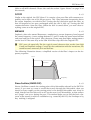
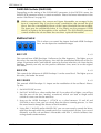
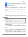
1
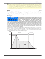
PPG Wave 2.V
Waldorf-Music will not be liable for any erroneous information contained in this
manual. The contents of this manual may be updated at any time without prior notice. We have made every effort to ensure that the information herein is accurate and
that the manual contains no contradictory information. Waldorf accepts no liabilities
in regard to this manual other than those required by local law.
This manual or any portion of it, may not be reproduced in any form without the
manufacturer's written consent. All product and company names are or trademarks of their respective owners.
Waldorf-Music, Germany 2006
www.waldorfmusic.de
Programming:
Wolfram Franke
Additional Programming:
Stefan Stenzel und Jürgen Fornoff
Graphic Design:
Steinberg Soft- und Hardware GmbH
Manual/ Layout:
Holger "Tsching" Steinbrink
Sound Designers and Beta Testers:
Volker Barber, Drew Neumann, Christian Halten, Uwe G. Hoenig, Jörg Hüttner,
Michael Johnson, Thomas Kircher, Till Kopper, Dirk Krause, Peter Kuhlmann, Nikki
de Leon, Manfred Maraun, Hans-Jörg Nonn, Mark Pulver, Matt Skaggs, Sven
Steglich, Holger Steinbrink, Wolfgang Thums
Special Thanks to Wolfgang Düren, Achim Flor, Yvan Grabit, Michael Michaelis,
Manfred Rürup, Stefan Scheffler and Karl Steinberg.
Waldorf
2
Operation Manual
PPG Wave 2.V
Content
The User Interface Panel .................................10
Introduction.......................................................4
How near is the PPG Wave 2.V to the
Original?.........................................................4
Differences to the Original PPG Wave 2.3 5
The Controls ................................................ 11
Key Combinations....................................... 12
Hiding the Keyboard................................... 12
System Requirements Windows........................5
The Program Menu..........................................13
Installation under Windows ...............................5
The Analog User Interface...............................13
System Requirements Mac OS ..........................6
DIGITAL Menu (DIGI).......................................19
Installation under Mac OS .................................6
TUNING Menu (TUNE) .....................................23
Using the PPG Wave 2.V under a VST or
AudioUnit host ..................................................7
MODULATION Menu (MOD).............................25
Graphical Editor (GRAPH)...............................28
Using the PPG Wave 2.V .............................7
Audio Channels of the PPG Wave 2.V .......7
Selecting and Playing Programs...................8
Storing Banks and Programs.........................8
Importing VST or AudioUnit Presets into
the corresponding plug-in format................8
Copying, inserting and comparing
Programs.........................................................9
Concluding Remarks.......................................28
Glossary .........................................................29
MIDI Controller List .........................................34
Controller List for the Novation Remote SL.....35
MIDI Functions ..................................................9
Controlling the PPG wave 2.V through the
Novation remoteSL............................................9
PPG Wave 2.V Polyphony................................10
Operation Manual
3
Waldorf
PPG Wave 2.V
Waldorf PPG Wave 2.V Software Synthesizer
Introduction
Thank you for your purchase of the Waldorf PPG Wave 2.V software synthesizer. The
PPG Wave 2.V is the software version of the legendary PPG Wave 2.3 synthesizer,
which was released in 1983. The PPG Wave 2.V combines the unique Wavetable
synthesis sound of the original synthesizer with the advantages of a software Plug-In. In
the end of 1970, the German company PPG came up with the idea, to copy the sound
and behaviour of analog circuits and replace it with a digital representation of oscillator
waveforms. In this process, different successive waveforms were stored in Wavetables.
While passing through, the sound changed its character, which could be controlled by
using envelopes, LFOs or other control sources. This resulted in a sound which
continuously changed its character and enabled soft transitions between similar sounding waveforms or extreme jumps between totally different sound spectra. With their
additional subsequent analog filters, the PPG synthesizers quickly reach cult status and
their typical “Wave sound” could be heard on a great number of music productions of
their time. We at Waldorf have successfully on-developed Wavetable synthesis for
many years. But there are still many fans of the initial powerful PPG sound around.
How near is the PPG Wave 2.V to the Original?
To give you a simple answer: very near! An example: the filter in the original PPG was
a SSM 2044 chip. If the resonance was increased, this filter attenuated the input signal
by up to 12dB. The PPG Wave 2.V works exactly like that. Furthermore, the resonance
of the SSM 2044 had a very special character, which in this form is not implemented in
any other filter circuit or IC. If you have the chance to listen to and directly compare
both the original and the Plug-In, you will find, that the resonance (or Emphasis, as it’s
called in the PPG) of both sounds absolutely identical. Another characteristic of the original PPG was its Aliasing noise – actually a side-effect during the reproduction of digital signals – which added an originally undesired noise level to the sound. Actually, it
is very simple to create Aliasing. But creating a type of Aliasing that has the same behaviour as on the PPG, is a challenge. In the PPG Wave 2.V you can even choose,
whether you want Aliasing or not. The only thing, that we did not emulate, was the
hum noise of the display back-lighting. We assume, that nobody really wants to use this
“feature”. There are many more factors, that are responsible for the typical PPG sound
and we are proud to say that we have found them all and reproduced them in our Wave 2.V.
Waldorf
4
Operation Manual
PPG Wave 2.V
Differences to the Original PPG Wave 2.3
From today’s viewpoint, some functions in the original PPG Wave 2.3 are not up-todate. For this reason, we have made a view changes to the Plug-In user interface, compared to its brother in hardware:
The naming of the different menus: In the original, there were PROGRAM, DIGITAL,
TUNING, ANALOG and SEQUENCE. The ANALOG menu displayed the dial parameters as numerical values in the display. This helped the user to compare between
the physical dial setting and the actually set parameter value of the current sound. In
the PPG Wave 2.V this menu is not necessary, as the dials show the settings of the
selected sound at any time. The SEQUENCE menu was used to call up the built-in
sequencer of the original PPG. This had a very simple structure and could in no way
compare to the power of a modern software sequencer, which is why we haven’t
included it in the Wave 2.V. Still present are the Arpeggiator and the possibility to
record parameter changes using MIDI Controller messages. In addition, the PPG
Wave 2.V has two new menus: MODULATION shows all possibilities for modulation within one menu, while the GRAPH menu offers graphic envelope and filter editing.
The second difference lies in the parameter names that are used: On the original
PPG, quite cryptic names were used for a number of functions (e.g. MF for the filter
modulation or SW for sub-oscillator behaviour). In the PPG Wave 2.V, these names
are either not abbreviated or the abbreviation makes sense.
The third difference concerns the display of values. On the original PPG, even switches only used numerical values. The parameter SUB-WAVES, which had the values
OFF, OFFSET, DIRECT and ENV3. These were represented by the numbers 0, 1, 2
and 3 (where 3 oddly enough stood for OFF). The PPG Wave 2.V offers an approach that’s a little more comprehensible.
System requirements Windows
In order to be able to use PPG Wave 2.V you will need at least:
A PC with a Pentium III / AMD Athlon 600 processor or better
64 MB free RAM
Windows 2000 / XP
VST 2.0 compatible host application supporting virtual instruments, such as Cubase
VST 3.7 or higher, Cubase SX / SL / SE or Nuendo 1.5 or higher. This must be correctly installed on your computer.
�
Please also observe the system requirements of your host application!
Installation under Windows
Proceed as follows to install the PPG Wave 2.V:
1. Start your computer and launch your operating system.
2. Insert the PPG Wave 2.V CD-ROM into your CD-ROM drive.
Operation Manual
5
Waldorf
PPG Wave 2.V
If you have enabled the Autostart function in Windows, the Installer will start automatically and you can proceed with Step 6 below. If not, please proceed as follows:
3. Launch the Explorer or open the “My Computer” window.
4. Double click on the icon for the CD-ROM drive that holds the PPG Wave 2.V CDROM.
5. Double click on the PPG Wave 2.V Installer icon. This launches a special installation
program.
6. Follow the on-screen instructions
The PPG Wave 2.V CD-ROM is your verification that you have purchased the program.
Please store it in a safe place. If you lose it, you have lost the Program.
�
Please note the “Read Me!” and “Important Changes” text files on the PPG Wave
2.V CD-ROM, which contain additionals information and/or any changes.
System Requirements for Mac OS
In order to be able to use the Waldorf PPG Wave 2.V, you will need at least:
Macintosh with 400 MHz G4 PowerPC processor or better
Mac OS X 10.3.9 or newer
128 MB free RAM
or
Macintosh with 1.5 GHz Intel CoreSolo processor or better
Mac OS X 10.4 or newer
128 MB of free RAM.
A VST 2.0 compatible host application that supports virtual instruments, such as Cubase SX / SL / SE or Nuendo. This must be correctly installed on your computer.
or
An AudioUnit 2.0 compatible host application that supports AudioUnit Instruments,
such as Apple Logic or GarageBand. This must be correctly installed on your computer.
�
Please also observe the system requirements of your host application!
Installation under Mac OS
Proceed as follows to install the PPG Wave 2.V:
1. Quit all other applications so that you return to the Finder. Disable any system activity monitoring software or extension, in particular anti-virus software. Then insert the
PPG Wave 2.V CD into your computer’s CD-ROM drive.
2. If you need to, double click on the PPG Wave 2.V icon to open the CD window.
3. Double click on the PPG Wave 2.V Installer icon to load the installation software.
Follow the instructions on the screen.
Waldorf
6
Operation Manual
PPG Wave 2.V
The PPG Wave 2.V CD-ROM is your verification that you have purchased the program.
Please store it in a safe place. If you lose it, you have lost the Program.
�
Please note the “Read Me!” and “Important Changes” text files on the PPG Wave
2.V CD-ROM, which contain additional information and/or any changes.
Using the PPG Wave 2.V under a VST or AudioUnit host
For users of VST or AudioUnit (Macintosh only) compatible host applications, Waldorf
offers the PPG Wave 2.V as a completely plug-in-based synthesizer that fully utilizes
Steinberg's VST and Apple's AudioUnit interface technology. If you wish to use it in a
VST or AudioUnit compatible host application, please consult its documentation to find
out what you have to do to set up the plug-in.
Using the PPG Wave 2.V
If you click on the keys of the built-in keyboard, you will hear the corresponding
notes.
If you don’t want to exclusively play the PPG Wave 2.V from the integrated screen
keyboard, make sure that your host application receives MIDI data that you generate
with your external MIDI Master keyboard.
Now you can play PPG Wave 2.V via MIDI, like any other instrument and record what
you play on a MIDI Track. To make sure, press a key on your MIDI keyboard. You
should now hear a sound. If you don’t hear anything, check first, whether your host application receives MIDI data at all.
�
The PPG Wave 2.V can receive MIDI data on eight MIDI channels. You should
therefore make sure that the channel setting within the PPG is the same as the
MIDI channel setting of the selected MIDI Track.
Audio Channels of the PPG Wave 2.V
The audio signals created by a virtual instrument are routed to the Channel Mixer of
your host application. Open this Mixer. For each open PPG Wave 2.V Plug-In, you find
two stereo channel strips in the Channel Mixer. These are named with an abbreviation
of the Program name (PPG Wav). By using the “Out 3-4” controls in the Plug-In, you
can assign the audio signals to the respective output channel pair. Find more information on page 19 of this manual.
Using the Channel Mixer, you can comfortably mix the signals created with the PPG
Wave 2.V and treat them in the same way as Audio Tracks. You can apply EQ, effects
or other external studio gear and process the audio in diverse ways.
If needed, you can transform any or all PPG Wave 2.V tracks into an audio file. To do
this, simply use the “Export Audio” function of your host application. Please find more
information in the corresponding documentation.
�
To get the most out of the PPG Wave 2.V, please make sure that you use the latest
software version of your host application.
Operation Manual
7
Waldorf
PPG Wave 2.V
Selecting and Playing Programs
A PPG Wave 2.V Sound Bank consist of 128 Sound Programs. The PPG Wave 2.V comes with several preset Sound Banks, created by renowned sound designers. The original factory presets of the PPG Wave 2.3 synthesizer are also included.
A Program consists of a complete set of parameters for one of the eight channels, available in the PPG Wave 2.V.
You can load complete banks or single programs. For information on loading, please
read the corresponding manual section of your host application.
To select a Sound Program from a Bank, please proceed as follows:
Click on the Program name in the PPG Wave 2.V display and hold down the mouse
button. This brings up a pop-up menu with all Program names of the current Bank.
Select the desired Sound Program by clicking on a menu entry.
Storing Banks and Programs
In the PPG Wave 2.V, you can save both single Sound Programs or a complete Sound
Bank. An exception is the AudioUnit version of the PPG Wave 2.V on the Macintosh.
There you can only save complete Sound Banks.
You can save complete banks or single programs. For information on saving, please
read the corresponding manual section of your host application.
When you save your song or project file, the following information is saved with it:
The number of PPG Wave 2.V modules used in the Song
Which Banks and Programs were used
Even the changed settings of edited Programs are stored
�
However, if you wish to use the edited version of a program in another song, then
you must save it manually before.
Importing VST or AudioUnit Presets into the corresponding plug-in format (Macintosh only)
VST and AudioUnit use different formats to save the plug-in data. If you had created a
program in a VST host and want to use it in an AudioUnit host (or vice versa), please
proceed as follows:
Save the program in the original host as a single Preset or Program. In VST hosts,
those files typically have the suffix „fxp“, in AudioUnit hosts they are called „aupreset“.
Quit that host and start the other host that supports the corresponding plug-in format. Open an instance of the plug-in.
Shift+Click on the Program button.
Select the file to import from the Open dialog.
Confirm the selection with OK.
The Preset or Program is loaded and can be played as usual.
Waldorf
8
Operation Manual
PPG Wave 2.V
Copying, inserting and comparing Programs
Using the COPY button, you can copy the current Sound into a clipboard memory and
from here paste it into another Program slot using the PASTE button. This can e.g. be
useful, if you wish to quickly stack several Sounds of similar type in the Program menu,
and play the slightly different versions. If the clipboard contains a sound, the COPY
button lights up in red, until you have pasted it somewhere else.
Please note that the clipboard can only contain one sound program at a time. If you use
COPY to copy a second sound into the clipboard, the first will inevitably be deleted.
Provided that you have not deleted it by copying again, a Sound that you have inserted
somewhere using PASTE, remains to be available on the clipboard and can be pasted
into other Program slots.
An edited and the original sound can at any time be compared with the Compare function (CMPR).
If you press the CMPR button, it lights up in red, indicating that Compare is active,
and the sound changes back to its original settings. Pressing CMPR again, brings
back the edited version.
If you hold down [Shift] while you press the CMPR button, the Sound will immediately set back to its original settings and the edited version is abandoned.
When Compare is active, you can get the same effect by simply changing the Sound
Program. Use one of these two methods if you are not satisfied with your edited
Sound.
If you click on AKKU, then the selected sound is set back to its default settings.
If you hold down [Alt] while pressing the AKKU button, a random sound is created
(similar to the original PPG, which did this, when its internal battery was empty).
You really should try out this function, as new interesting Sounds can be created this
way.
MIDI Functions
The PPG Wave 2.V’s MIDI interface is more or less identical with that of most synthesizers. As soon as the MIDI connection is set up, the PPG Wave 2.V can be played across
the whole MIDI note range. Same as the original synth, the Plug-In can process monophonic Aftertouch data, provided you use a keyboard that generates this data type.
You can remote-control the PPG Wave 2.V controls using an external MIDI Controller
device (fader box) or a Master keyboard. MIDI Controller data can of course also be
created graphically or numerically in respective editors of the host. A table listing the
available MIDI Controllers can be found on page 34 of this manual.
Controlling the PPG Wave 2.V through the Novation RemoteSL
Certain parameters of the PPG Wave 2.V can be controlled through the Novation RemoteSL. The RemoteSL offers 24 encoders, potentiometers and sliders that can be mapped on up to 72 different parameters.
The PPG Wave 2.V is 8 times multi-timbral which means that it has far more than these
72 parameters. Therefore, we limited control to the parameters of MIDI Channel 1. The
corresponding controller list can be found on page 35.
Operation Manual
9
Waldorf
PPG Wave 2.V
�
The host application must support the Novation RemoteSL and its „AutoMap“
feature to be able to control the Attack. Please read the documentation of the corresponding host application.
PPG Wave 2.V Polyphony
The PPG Wave 2.V has up to 64 voices. The number of available voices depends on
the available processor power. The number of voices can easily be set on the Plug-In user interface. All you have to do, is use the mouse button to increase or decrease the
value in the VOICE display. This is a global setting. It also affects all other Multi mode
channels.
You should always increase the VOICE number, if you wish to play the PPG Wave 2.V
in duophonic or quadrophonic mode, or if you want to play back several sound programs simultaneously. Find more information in the section “The Program Menu” on
page 13 of this manual. Keep in mind that each additional voice demands additional
calculating power from your computer. Try to set the number of voices to a sensible
value, if you simultaneously use other Plug-Ins and if you also play back audio tracks
with your host application.
�
Hint: Only voices that sound create processor load. VOICE only controls the maximum number of simultaneously possible voices.
The User Interface Panel
By and large, the PPG Wave 2.V user interface panel corresponds to that of the original PPG Wave 2.3. But why are not all parameters displayed in the form of faders,
although this would easily be possible within such a digital environment? The reasons
for this lies in the fact, that the character of a synth is not only rooted in its sound but
also in its access methods. That is why the analog user interface panel of the PPG Wave 2.V displays all parameters as dials, same as it was the case on the original. All other
menus each consist of a large display, which contains the respective parameters in the
form of an “LCD” display.
The following illustration shows a graphic representation of the signal flow. The next
sections of this manual explain each function in detail.
Waldorf
10
Operation Manual
PPG Wave 2.V
The Controls
Simply use the mouse to set the PPG Wave 2.V controls.
Dials: To set this control, click on it, hold down the mouse button and drag the
mouse around the dial in a circle. Dragging in a greater circle increases the value resolution that is available. The PPG Wave 2.V display simultaneously shows the actual value of the corresponding parameters. If you prefer vertical mouse movement to
change a value, then you can set the PPG Wave 2.V into this mode. Just hold down
the [Shift] key on your computer keyboard and click on the PPG-logo. To set this
back to normal mode, Shift/click again.
Display: The Display shows the current Sound number
and the Sound name. If your turn a dial. its numerical value is shown in the display.
A mouse click on the sound number opens a pop-up menu with the available
Sounds. Find more information in the section “Selecting and Playing Programs” on
page 8 of this manual.
Switches: By clicking a switch once, you switch the corresponding function On or Off.
Buttons: A mouse click on a button activates a function. The DIGI button can
for instance be used to open the DIGITAL menu. Except for the KEYB. button, buttons light up in red when they have been used. Button states are not saved with Programs.
Value Selectors: Position the mouse pointer on the value, hold down
the mouse button and drag up or down.
Operation Manual
11
Waldorf
PPG Wave 2.V
Graphic Display: Click on one of the handles to continuously and
smoothly change the envelope parameters or click into any envelope phase to let its
value jump there.
Filter Response: Click into the graphic display to simultaneously change
Cutoff and Emphasis.
Wheel: To change the value, click on the wheel and drag the mouse up or
down. The Pitch-Bend wheel snaps back into its center position as soon as
you let go of the mouse button.
If you click on the PPG or the Waldorf logo, a “program
information” window opens.
Key Combinations
If you hold down the [Alt] key on your computer keyboard and click on any control,
its value is automatically set to its default value (e.g. Cutoff is set to 63, Emphasis is
set to 0 or modulations are set to OFF).
You can increase the resolution of a dial, value selector or wheel by holding down
the [Shift] key on your computer keyboard when you use the respective control. If a
dial is set to “circle mode” (you change a value by dragging around the dial in a
circle), then you can temporarily change to “up/down mode” by holding down
[Shift]. Find more about dial modes on page 10.
If you hold down the [Ctrl] (on the PC) or [Command] key (on a Macintosh computer) when you click on a control, its value is displayed in the Sound-Display without
being changed.
Hiding the Keyboard
Same as the original, the PPG Wave 2.V provides a standard keyboard (61 keys). If your
monitor gets crammed with windows, you can hide the keyboard by pressing the KEYB
button. Pressing the button again lets the keyboard pop up again.
Waldorf
12
Operation Manual
PPG Wave 2.V
The Program Menu
In the PPG Wave 2.V, you can simultaneously create up to eight different sounds. This
function is generally called Multi Mode. Which of the eight sounds you play, depends
on the MIDI Send channel that you use in your host application.
You can use the Program menu to select sounds for the eight MIDI channels.
To select the desired Sound Program for a channel, click on its sound name and select a Program in the appearing pop-up menu.
If you wish to play the Sound Program of the selected channel, you must set the
MIDI channel of the active Track in your host application to the same channel.
Please note that the PPG Wave 2.V only receives MIDI data on MIDI-channels 1 to 8.
Channels 9 to 16 are ignored.
�
Please note that a sufficient number of voices should be set on the PPG Wave 2.V
if you use the Program Mode, as otherwise voice “bottlenecks” could quickly
happen.
The Analog User Interface
The analog user interface offers direct access to the dials on the PPG Wave 2.V. The
Pitch Bend and Modulation wheels can be controlled both from within the Plug-In and
from your Master keyboard. Same as on the original PPG Wave 2.3, the setting of the
Modulation wheel is stored separately for each Sound Program. This lets you save a
sound with preset modulations.
The analog user interface is automatically active when you start the Plug-In. To get
back to the analog user interface from within a menu, press the corresponding Menu
button again (it will light in red).
All dials and functions are explained in the following sections.
0...63
BASIS
The Basis dial controls the position of voices within the stereo panorama (pan). If this is
set to 0, all voices are audible in the middle of the stereo spectrum. If you turn it to the
right, voices in POLY mode alternate between a left and a right pan position. In DUAL,
Operation Manual
13
Waldorf
PPG Wave 2.V
QUAD and MONO modes, voices are equally spread within the stereo spectrum. This
function only makes sense, if you monitor your audio signal in stereo.
�
In contrast to the original PPG, where it could happen that two voice would
sound on the same channel, voices in the PPG Wave 2.V always sound alternatively for each channel.
0...63
VOLUME
This dial is used to set the output volume of a Program. It is a good idea to the lower
the Volume value, if the sound tends to distort anyway because of its settings. In Program mode, this allows you to use sounds with different volumes.
�
VOLUME is not Master-Volume, it only applies to the respective MIDI channel.
Use the channel mixer in your host-application, if you want to reduce the overall
volume of the Plug-In.
LFO
LFO (Low Frequency Oscillator) is an oscillator that creates
an oscillation below the threshold of audibility. These can be
used to continuously control different parameters (e.g. to
control the WAVES, the FILTER or the pitch of the oscillator).
The PPG Wave 2.V’s LFO offers four different oscillator
waveforms as modulation signal. modulation intensity can be controlled with the Modulation wheel (MODWHEEL). If it is fully turned down, no modulation takes place.
Same as on the original PPG Wave synth, the Modulation wheel setting is saved with
each Program. Make sure that TOUCH>MOD in the MODULATION menu is set to
OFF, otherwise the LFO will only modulate the signal if Aftertouch data is generated at
the same time.
The LFO can also be synchronized to the Song tempo of your host application.
�
The original PPG LFOs were calculated with a very low update rate, as back
then, the available processor power had to be carefully distributed to the various
tasks. In the PPG Wave 2.V you can get this low update rate, if you activate TRUE
PPG.
0...63
DELAY
This parameter enables a smooth LFO modulation intensity attack.
�
If TRUE PPG is deactivated, DELAY doesn’t have an impact when set to zero. If
TRUE PPG is active, the LFO is faded in with any new key that you press, irrespective of the DELAY parameter setting.
Triangle, Saw down, Saw up, Square
WAVESHAPE
The LFO can create the following four waveforms: Triangle, falling saw tooth, rising
saw tooth and Square. You can use this control to select one of these waveforms.
Waldorf
14
Operation Manual
PPG Wave 2.V
�
Same as on the original PPG, the LFO waveform Square jumps between “no modulation” and “full positive modulation”. The other three waveforms oscillate
between “full negative modulation” and “full positive modulation”. You can
clearly notice this effect, if you activate MOD>FILTER and switch back and forth
between the various waveforms.
0...63
RATE
The Rate dial controls the LFOs speed. If this is set to its minimum value, the LFO operates with 0.09 Hz (one cycle in 10,6 seconds). If Rate is set to its maximum value, the
LFO speed reaches 24 Hz (i.e. 24 cycles per second).
Envelopes
An Envelope creates a time-wise variable control signal. It is
for instance used to modulate the filter settings of a sound
within a given period of time. The classic Envelope form
consist of four separately controllable phases: Attack,
Decay, Sustain and Release, which is why it is also called ADSR Envelope. If you press
a key, the Envelope is started. Within the period of time that you have defined with the
ATTACK parameter, it first rises to its maximum value. Then it needs the time set with
the DECAY dial to fall to the value set with the SUSTAIN dial. It remains there until
you let go of the key. Then the Envelope sinks back to zero within the period of time
that you have set with the RELEASE dial.
The PPG Wave 2.V has two ADSR and one AD Envelope with positive or negative deflection, which can also be edited graphically. Find additional information in the section “Graphical Editor (Graph)” on page 28 of this manual. The illustration below
explains the structure of a classic ADSR Envelope:
Depth
Key pressed
Key released
100%
Sustain
Attack
Operation Manual
Decay
Release
15
Time
Waldorf
PPG Wave 2.V
�
The original PPG had an especially interesting feature, which can of course always be found in the Plug-In. If the Attack Rate of an Envelope was set to a value
higher than 47, then the signal would execute the Attack-phase completely, no
matter if the note was still played or not. The the Envelope would always switch
into the Release-phase. This function is especially useful for long filter-sweeps. For
this to work, Envelope 2, which controls the volume, must of course also be set
correspondingly.
A,D,S,R each 0...63
ADSR ENVELOPE 1
This Envelope is used to control the filter frequency and the waveforms. The four dials
control the exact Envelope form and time-wise modulation development. The impact of
the Envelope on the filter frequency can be adjusted with the ENV1-VCF parameter, the
intensity of waveform modulation is changed with the ENV1-WAVES parameter.
A,D,S,R each 0...63
ADSR ENVELOPE 2
This Envelope is used to control level development. The four dials control the exact Envelope form and time-wise modulation development of the sound’s level. The intensity
of this Envelope can be controlled with the ENV2 VCA parameter.
A,D, ATT each 0...63
AD ENVELOPE 3
This Envelope can be assigned to different modulation targets. Attack and Decay behave as usual, but the signal always travels through the Envelope completely, no matter if
a note is held or not.
If ENV3>OSC or ENV3>SUB in the TUNE menu are active, Envelope 3 modulates the
pitch of the corresponding oscillator. ENV 3 ATT either controls a negative (when turned counter clockwise) or a positive (when turned clockwise) Envelope deflection. If
SUB-WAVES in the DIGITAL menu is set to ENV3, then Envelope 3 modulates the sub
oscillator waveform. In this case, only the positive deflection form of ENV 3 ATT can be
used.
�
All three Envelopes can also graphically be edited in the GRAPH-Editor.
Modifiers
This section creates the actual sound. Two Wavetable
oscillators (OSC and SUB) as well as a 24dB low pass filter
with resonance capability. Sound creation in the PPG
Wave 2.V bases on waveform sets, called Wavetables. You
should think of these as a sequence of up to 64 single Waves. This can be played back
in a static way or passed through dynamically, which results in the PPG-typical interesting sound transformations. If the Waves do not differ much, then the Wavetable will
probably sound smooth and pleasant. If they have a completely different structure, this
will result in abrupt spectral changes.
The PPG Wave 2.V contains 32 Wavetables and the last four Waves of each Wavetable
are always the classic analog waveforms Triangle, Pulse, Square and Saw tooth. You
should thus first use these four waveforms, if you want to create typical analog sounds.
Additionally, you have the UPPER WAVES, another Wavetable, which is always avai-
Waldorf
16
Operation Manual
PPG Wave 2.V
lable on all MIDI channels. Please also read the section “Upper Waves” on page 20 of
this manual).
0...63
CUTOFF
Similar to the original, the PPG Wave 2.V contains a low pass filter with resonance capability and a slope rate of 24 dB per octave. This filter attenuates frequencies above
the corner frequency set with the dial. Turning the dial clockwise opens the filter, so
that all frequencies can pass unchanged when the dial is fully up. Turning the dial
counterclockwise closes the filter. When the dial is turned down, you won’t hear anything, same as on the original PPG.
0...63
EMPHASIS
Emphasis, often also named Resonance, emphasises a narrow frequency band around
the corner frequency. Lower settings between 15 and 50 make the sound more brilliant
and nasal and give it the typical filter character. Please note that higher settings attenuate the level in the same way as the SSM 2044 filter chip did in the original PPG.
�
PPG users do especially like the typical sound character that results from high
Cutoff and Emphasis settings. Caused by the combination with the waveforms, the
sound becomes extremely thin and delicate.
The following illustration shows a simplified version of the filter’s impact on the frequency response:
Level
Resonance
Frequency
Cutoff
0...63
Waves-Oscillator (WAVES-OSC)
Waves-Oscillator controls the starting point of the Wavetable selected in the DIGITAL
menu. If you want to create a sound that travels through the Wavetable, then you
should at least roughly set the starting point in the desired Wavetable area. Keep in
mind, that the last four Waves 60 to 63 are the same in all Wavetables, so that unwanted “jumps” can occur during the pass. This method helps you to find the basic character of the sound, to which a modulation (e.g. caused by the LFO, the Envelope or by
Key tracking) is assigned.
Operation Manual
17
Waldorf
PPG Wave 2.V
WAVES-SUB-Oscillator (WAVES-SUB)
0...63
Depending on the setting of the SUB-WAVES parameter in the DIGITAL menu, the
WAVES-SUB parameter selects a certain waveform. Please find more information in the
section “Sub Waves” on page 20.
�
Within sound-memory, the current and Upper Wavetables are arranged in the
form of a sequential ring. If you thus create a modulation, that exceeds the 63rd
Wave, then the corresponding Waves of the Upper Wavetable become audible.
The same goes for modulations below 0. You simply use the parameter UPPER
WAVES to replace the Wavetables of the oscillator. The SUB-WAVES parameter
controls whether the sub oscillator also uses these replaced Wavetables.
Modifiers Control
This is where you control the impact that both ADSR Envelopes
have on the respective modulation target.
0...63
ENV 1 VCF
This controls how ADSR Envelope 1 influences the filter frequency. The higher you set
this value, the more the filter frequency rises with the modulation deflection of the Envelope. Experiment with Cutoff and this control to find out what they do. Note that the
Envelope intensity can only use the positive deflection form, same as on the original
PPG Wave.
0...63
ENV 2 VCA
This controls the influence of ADSR Envelope 2 on the sound level. The higher you set
this value, the louder the sound.
0...63
ENV 1 WAVES
This controls ADSR Envelope 1’s impact on the modulation of the oscillator’s Waves.
Try this:
1. Set WAVES-OSC to zero.
2. Set ENV1 WAVES to a value smaller than 60. If you select 60 or higher, you will get
into the area of the four “analog” waveforms, which can lead to rough sound
(which of course can also be attractive).
3. Now set the ADSR Envelope 1 ATTACK to a value between 32 and 40 and
SUSTAIN to zero. Now you can clearly hear the Wave scanning process, i.e. how
the sound travels through the Waves of the Wavetable.
4. Using ENV 1 WAVES and/or WAVES-OSC you can now exactly control the Wavetable area through which the sound travels in a certain period of time. You can additionally scan the sub oscillator’s Wavetable with ENV 3, which facilitates interesting sound transformations.
Waldorf
18
Operation Manual
PPG Wave 2.V
LFO SYNC
Press this button to synchronize the LFO to the tempo of your Song. If LFO
Sync is active, the corresponding LED lights up in red. This does only work,
if your host application is capable to transfer the appropriate time
information to the PPG Wave 2.V.
TRUE PPG
If you activate this function, the PPG Wave 2.V is set into a special mode where it
shows the same peculiarities in behaviour that its original model showed. The LED
lights up in red, if the function is active.
You hear the typical Aliasing noise of the original PPGs, especially when creating
higher notes.
The LFO oscillates irregularly, LFO Delay set to zero fades in the LFO with each
newly started note.
Filter tuning varies slightly to simulate the tuning instability of the analog filter chip.
OUT 3-4
The PPG Wave 2.V has four audio outputs, grouped into two stereo pairs. You can use
this switch to route the selected sound onto the alternative audio output. You can e.g.
use this function to assign different effects or EQ settings to Sounds in Program mode.
DIGITAL Menu (DIGI)
The Digital menu lets you access the Wavetable parameters, their modulation, Sound
Layering and the Arpeggiator.
To open the Digital menu, press the DIGI button on the Plug-In panel. The button lights
up in red. Pressing it again lets you switch back to the analog user interface.
The next sections describe the individual functions in detail.
0...square
WAVETABLE
This parameter is used to select the Wavetable for both Wave oscillators. 32 different
Wavetables are available, as on the original PPG. The Wavetables are the PPG Wave
2.V’s driving force. To make sure that you fully use this power, you should familiarize
yourself with the sound and the characteristics of each Wavetable.
To travel through the Wavetables it is advisable to first initialize a popular Program by
pressing the AKKU button. Continuously hold down a key on the keyboard (preferably
the note C4). Envelope 1 is programmed to slowly travel through all Waves of the seOperation Manual
19
Waldorf
PPG Wave 2.V
lected Wavetable (except for the last four “analog” waveforms). Change the Wavetable
to hear how the various Wavetables sound. You will find that they cover a wide
spectrum of interesting sound colours, including analog, FM typical or bell-type
sounds. If you wish to increase the “travel speed”, then decrease the Decay value of
Envelope 1 correspondingly.
ON, OFF
UPPER WAVES
In addition to the 64 Waves per Wavetable, Upper Waves are available. This is another
Wavetable, which provides another 64 Waves. Click ON to activate the Upper Waves.
The Upper Waves reside above the regular Wavetables and expand the Spectrum of the
Wave scanning. Only one Upper Waves “Wavetable” is available and it is identical for
all Wavetables.
�
The original PPG Wave 2.3 could only provide the upper Wavetable to the
Sound on the first Part. In the PPG Wave 2.V Plug-In UPPER WAVES can be active on each channel.
OFF, OFFSET, DIRECT, ENV 3
SUB-WAVES
Use this function to activate the Sub Wave oscillator. Four different settings are possible:
OFF switches the Sub oscillator off. The Wave oscillator will sound twice as loud to
compensate for the difference in volume.
OFFSET is the preferred setting. In this mode, the value to which WAVESSUB is set,
is added to the value set for WAVES-OSC. If you e.g.set WAVESOSC to 20 and
WAVES-SUB to 10, the oscillator will play Wave 20, while the sub oscillator will
play Wave 30. Offset can also be used in connection with the possible Wave oscillator modulations. The switch UPPER WAVES also applies to the sub oscillator in
this setting, as this still concerns an Offset between sub oscillator-waveform and oscillator-waveform.
DIRECT means that the WAVES-SUB dial plays the set waveform directly, and that
no modulation can change it. If you e.g. want to perform a Wavescan only for the
main oscillator, while the sub oscillator should play a fixed wave, then select this
setting. The switch UPPER WAVES has no impact here.
ENV 3 is identical with DIRECT, except that Envelope 3 is used as the modulation
source for the Wave scanning of the sub oscillator. You can use this setting to create
oppositely directed Wave modulations of the two oscillators. The switch UPPER
WAVES has no impact here.
0%...233%
KEY>WAVES
This parameter allows you to play different Waves of a Wavetable with different notes.
If this is set to 100%, each key on the keyboard triggers a different Wave. The C1 key
triggers the waveform, that you have selected with WAVES-OSC or WAVES-SUB, while
higher keys trigger lower waveforms. This reversed direction was used on purpose, as
most Wave sets start out with dull waveforms and become increasingly brighter with
higher waveform numbers. Using this function on Wavetable 0, lets you for instance
create an electric piano sound, or you use it on Wavetable 27 to get the famous “PPG
choir”.
Waldorf
20
Operation Manual
PPG Wave 2.V
ON,OFF
MOD>WAVES
This parameter lets you use the LFO as a modulation source for Wave scanning. As
mentioned earlier, please keep in mind that the LFO modulation intensity can only be
set with the Modulation wheel. Thus, no modulation will take place, if the Modulation
wheel is all the way down. The setting of the Modulation wheel is stored with each
Program, same as on the original PPG Wave. Make sure that TOUCH>MOD in the
MODULATION menu is set to OFF, otherwise the LFO only modulates one signal, if
Aftertouch is generated at the same time.
�
To complete the picture, this parameter (MOD>WAVES) is also described in the
section “Modulation Menu (Mod)” on page 26 of this manual.
ON, OFF
TOUCH>WAVES
This parameter lets you use monophonic Aftertouch (Channel Pressure) to perform a
Wave scan. You can only use this function, if your Master keyboard is able to generate
Aftertouch data.
ON, OFF
BEND>WAVES
This parameter lets you use Pitch Bend to perform a Wave scan. As Pitch Bend normally snaps to a center setting, it is advisable to also set the Wave oscillator into a
center setting. This lets you create a bipolar modulation, i.e. one that reaches out to
both sides. Again, make sure to set WAVES-OSC to 29, as otherwise the maximum deflection of the pitch bent four analog waveforms of the Wavetable are also read out.
This can lead to unpleasant sound jumps (which can of course also be considered as
interesting). If you wish to prevent simultaneous pitch changes, then you should turn
the parameters MOD>OSC and SUB>OSC in the TUNING menu to OFF.
POLY, DUAL, QUAD, MONO
Keyboard Mode (KEYB MODE)
The Original PPG Wave 2.3 offered several options to stack voices. The SEMITONE parameters in the TUNING menu (see page 24) are directly connected with this function.
Not all original modes are found in the Wave 2.V, as it would not make sense because
of the dynamic voice assignment that is used nowadays. (Background: The PPG Wave
2.3 offered a maximum of eight voices). The most important and interesting Keyboard
modes have been taken over from the original:
POLY means that an incoming note only creates one voice. In Poly mode only
SEMITONE 1 controls the pitch of the played notes (in the Original PPG Wave, this
modes was named POLY 8x1).
DUAL means that an incoming note creates two voices. Here, SEMITONE 1 controls
the pitch of the first voice and SEMITONE 2 controls the pitch of the second voice
(in the Original PPG Wave, this modes was named QUAD 4x2).
QUAD means that each incoming note creates four voices. Here, SEMITONE 1 to 4
control the respective pitch of the four voices (in the Original PPG Wave, this modes
was named DUO 2x4).
MONO means, that each incoming note creates eight voices. Again, SEMITONE 1 to
8 control the respective pitch of the eight voices (in the Original PPG Wave, this
modes was named MONO 1 x 8). Please note, that only one note at a time can be
played. If you create another note while the first one ist still held, then the first will
Operation Manual
21
Waldorf
PPG Wave 2.V
be cut off. The note is not memorized. If you thus let go of the note of a chord, no
older note becomes audible.
�
Please read the section “Semitone” on page 24 of this manual.
ON, OFF
ARP ACTIVE
An Arpeggiator splits an incoming chord into single notes and repeats these dynamically. Different pattern presets can be used.
The PPG Wave 2.V Arpeggiator has a very simple structure and serves as a source for
sound sequence ideas and as a fun generator. I
f you set Arp Active to On, the Arpeggiator is switched on. Play a chord on your MIDI
keyboard to hear the effect.
UP, DOWN, ALT, RND, MOVING
ARP MODE
This parameter is used to determine the succession of created notes depending on their
pitch.
If this is set to UP, the Arpeggio starts with the lowest note and then plays upwards to
the highest note. Then it starts over again with the lowest note.
If this is set to DOWN, the Arpeggio starts with the highest note and then plays
downwards to the lowest note. Then it starts over again with the highest note.
If this is set to ALT (alternating), the Arpeggio starts with the lowest note and then
plays upwards to the highest note. Then it reverses course and plays the notes starting with the highest and ending with the lowest note.
The RND (Random) setting creates a random Arpeggio based on the notes that the
chord contains that you play.
The MOVING setting creates an Arpeggio with an interleave pattern. The note succession with five keys pressed is as follows: 1-2-1-3-2-4-3-5-4-1-5-2-1-3-2-4...
1/1...1/64t
ARP RATE
Arpeggiator Rate lets you control the note length of the created individual notes. You
can set values from a whole note to a 64th Triplet. The 4/4 time signature and the current Song tempo of the host application are used. Triplets (e.g. 1/8T) and dotted notes
(e.g. 1/16) are available for each note value.
1...4
ARP RANGE
Using Arpeggiator Range, you can control the number of octaves used for the Arpeggio.
Waldorf
22
Operation Manual
PPG Wave 2.V
TUNING Menu (TUNE)
The Tuning menu lets you access all parameters that concern the tuning and pitch modulation of the plug-in.
To open the Tuning menu, press the TUNE button on the Plug-In panel. The button
lights up in red. Pressing it again lets you switch back to the analog user interface.
The next sections describe the individual functions in detail.
0 CENTS...2 OCT
DETUNE
You can use this parameter to detune the sub oscillator compared to the main oscillator
and get flanging or chorus-type effects, or musically useful intervals. These settings are
possible:
The setting 0 CENTS does not create a detuning effect, which can cause the signal to
be out of phase.
The setting 3 CENTS detunes the sub oscillator by 3 cent.
The setting 6 CENTS detunes the sub oscillator by 6 cent.
The setting 9 CENTS detunes the sub oscillator by 9 cent.
The setting 12 CENTS detunes the sub oscillator by 12 cent.
The setting 7SEMI detunes the sub oscillator by 7 7 semitones (a Fifth) upwards.
The setting 1 OCT detunes the sub oscillator by one octave upwards.
The setting 2 OCT detunes the sub oscillator by two octaves upwards.
ON, OFF
MOD>OSC
This parameter can be used to select the LFO as a modulation source for the pitch of
the main oscillator. This creates a Vibrato effect. Please keep in mind that no modulation will take place, if the Modulation wheel is all the way down. The setting of the Modulation wheel is stored with each Program, same as on the original PPG Wave. Make
sure that TOUCH>MOD in the MODULATION menu is set to OFF, otherwise the LFO
only modulates one signal, if Aftertouch is generated at the same time.
ON, OFF
MOD>SUB
This parameter is identical with MOD>OSC, except that in this case the sub oscillator is
pitch modulated.
ON, OFF
ENV3>OSC
You can use this parameter to select the AD-Envelope 3 as a modulation source for the
pitch of the main oscillator. You can use this to create a rising pitch in the Attack phaOperation Manual
23
Waldorf
PPG Wave 2.V
se, for example. Using the ENV 3 ATT dial on the analog user interface, you control,
whether the deflection should be positive or negative.
ON, OFF
ENV3>SUB
You can use this parameter to select the AD-Envelope 3 as a modulation source for the
pitch of the sub oscillator. Using the ENV 3 ATT dial on the analog user interface, you
control, whether the deflection should be positive or negative.
OFF, BOTH, SUB
BEND>PITCH
This parameter lets you control the pitch changes that you make with the Pitch Bend
wheel.
You can make these settings:
OFF: The Pitch Bend wheel position doesn’t influence the pitch of the sound.
BOTH: The Pitch Bend wheel can be used to simultaneously change the pitch of
both oscillators.
SUB: The Pitch Bend wheel is used to only change the pitch of the sub oscillator.
The main oscillator’s pitch remains unchanged.
�
This parameter can also be found on the MODULATION menu.
400...499
TOTAL TUNE
This parameter changes the overall tuning of the PPG Wave 2.V. The value refers to the
reference pitch for MIDI note A3. The standard setting for this is 440 Hz, which is used
by most acoustic and electric instruments. We recommend that you only change the
overall tuning, if you are sure of what you’re doing. Please keep in mind to adjust the
tuning of all other use instruments, if you change Total Tune.
�
We have no idea, why this parameter was adjustable between 400Hz and 499Hz
in the original PPG. But to keep the charm of the original, we have implemented
it in the same way.
je 0...63
SEMITONE 1-8
These parameters are directly connected to KEYBOARD MODE in the DIGITAL menu
(also see the section “Keyboard Mode” on page 20). They are used to define the pitch
of the individual voices in the different play modes in semitone steps. If set a Semitone
value to “0”, then the corresponding semitone will wind up in the 32’ octave range. If
you set it to “12”, it winds up in the 16’ octave range etc.
SEMITONE 1 controls the pitch in POLY mode.
SEMITONE 1 and 2 control the pitches in DUAL mode.
SEMITONE 1 to 4 control the pitches in QUAD mode.
SEMITONE 1 to 8 control the pitches in MONO mode.
Waldorf
24
Operation Manual
PPG Wave 2.V
MODULATION Menu (MOD)
You can use the Modulation menu to make various settings that concern the modulation sources and their respective targets.
To open the Modulation menu, press the MOD button on the PlugIn panel. The button
lights up in red. Pressing it again lets you switch back to the analog user interface.
The next sections describe the individual functions in detail.
0%...233%
KEY>WAVES
This parameter allows you to play different Waves of a Wavetable with different notes.
If this is set to 100%, each key on the keyboard triggers a different Wave. The C1 key
triggers the waveform, that you have selected with WAVES-OSC or WAVES-SUB, while
higher keys trigger lower waveforms. This reversed direction was used on purpose, as
most Wave sets start out with dull waveforms and become increasingly brighter with
higher waveform numbers. Using this function on Wavetable 0, lets you for instance
create an electric piano sound, or you use it on Wavetable 27 to get the famous “PPG
choir”.
0%...233%
KEY>FILTER
This parameter determines, the degree to which the filter frequency depends on the
played MIDI note. The higher you set this value, the higher the filter frequency will rise
during play. For instance, if you set this to 100% and play an octave on the keyboard,
the filter frequency changes by the same amount. Please note that this is a unipolar
function, i.e. it only works in one direction.
10:1...1:10
KEY>LOUDNESS
This parameter defines the degree to which the level depends on the played MIDI note.
A setting of 10:10 changes will change nothing. Settings of 1:10, 4:10 or 7:10 will cause that lower notes sound less loud while settings of 10:8, 10:5, 10: 2 or 10:1 will cause
that higher notes sound less loud.
ON, OFF
VEL>FILTER
This parameter controls the Filter Envelope’s influence on filter frequency depending on
note velocity values. Use this function to add more expression to your sound.
ON, OFF
VEL>LOUDNESS
This parameter determines the degree to which the level depends on note velocity values. Use this function to add more expression to your sound.
Operation Manual
25
Waldorf
PPG Wave 2.V
�
The keyboard of the original PPG Wave 2.3 was not able to recognize note velocity, but it had a sensor for Aftertouch. This could be used to vary note velocity.
When a key was pressed, the Wave 2.3 calculated the velocity value of the next
note, based upon the detected Aftertouch data. To make things easier, we have
not implemented this method in the PPG Wave 2.V. It directly uses note velocity.
ON,OFF
MOD>WAVES
This parameter lets you use the LFO as a modulation source for Wave scanning. As
mentioned earlier, please keep in mind that the LFO modulation intensity can only be
set with the Modulation wheel. Thus, no modulation will take place, if the Modulation
wheel is all the way down. The setting of the Modulation wheel is stored with each
Program, same as on the original PPG Wave. Make sure that TOUCH>MOD in the
MODULATION menu is set to OFF, otherwise the LFO only modulates one signal, if
Aftertouch is generated at the same time.
�
To complete the picture, this parameter can also be found in the DIGITAL menu
section.
ON, OFF
MOD>FILTER
This parameter lets you use the LFO as a modulation source for the filter frequency.
Please keep in mind that the LFO modulation intensity can only be set with the Modulation wheel. Thus, no modulation will take place, if the Modulation wheel is all the
way down. The setting of the Modulation wheel is stored with each Program, same as
on the original PPG Wave. Make sure that TOUCH>MOD in the MODULATION menu
is set to OFF, otherwise the LFO only modulates one signal, if Aftertouch is generated at
the same time.
ON, OFF
MOD>LOUDNESS
If this parameter is set to ON, then the LFO will continuously modulate the level. Please take special note that this modulation is independent of the Modulation wheel setting. The LFO parameter DELAY doesn’t have any impact on this parameter. You can
use this parameter for to create a continuous Tremolo effect.
ON, OFF
TOUCH>WAVES
Provided that your Master keyboard can generate Aftertouch data, this parameter lets
you perform a Wave scan using monophonic Aftertouch (Channel Pressure).
ON, OFF
TOUCH>FILTER
Provided that your Master keyboard can generate Aftertouch data, this parameter lets
you control the deflection of the Filter Envelope – as set with the ENV 1VCF dial – by
using monophonic Aftertouch (Channel Pressure).
ON, OFF
TOUCH>LOUDNESS
Provided that your Master keyboard can generate Aftertouch data, this parameter lets
you control volume – as set with the ENV 2VCA dial – by using monophonic Aftertouch (Channel Pressure).
Waldorf
26
Operation Manual
PPG Wave 2.V
ON, OFF
TOUCH>MOD
This parameter lets you trigger an LFO modulation with monophonic Aftertouch
(Channel Pressure). For this to have any effect, please make sure that the Modulation
wheel is not turned all the way down. If it is, this parameter has no effect.
OFF, BOTH, SUB
BEND>PITCH
This parameter lets you control the pitch changes that you make with the Pitch Bend
wheel.
You can make these settings:
OFF: The Pitch Bend wheel position doesn’t influence the pitch of the sound.
BOTH: The Pitch Bend wheel can be used to simultaneously change the pitch of
both oscillators.
SUB: The Pitch Bend wheel is used to only change the pitch of the sub oscillator.
The main oscillator’s pitch remains unchanged.
�
This parameter can also be found on the TUNING menu.
ON, OFF
BEND>FILTER
If this parameter is set On, you can control the filter frequency with the Pitch Bend
wheel. Please keep in mind that the Pitch Bend wheel is a bipolar modulation source. It
can produce both positive and negative values.
ON, OFF
BEND>WAVES
This parameter lets you use the Pitch Bend wheel to perform a Wave scan. As Pitch
Bend normally snaps to a center setting, it is advisable to also set the Wave oscillator
into a center setting. This lets you create a bipolar modulation. Make sure to set
WAVES-OSC to 29, as otherwise the maximum deflection of the pitch bent four analog
waveforms of the Wavetable are also read out.
2 SEMI...1 OCT
BEND>INTERVAL
This parameter lets you control the interval in semitones, that is created, if the Pitch
Bend wheel has its respective maximum setting. These intervals are possible:
2 SEMI means two semitones
4 SEMI means four semitones
7 SEMI means seven semitones (Fifth)
1 OCT means one octave
The set interval also controls the strength of BEND>FILTER and BEND>WAVES in similar fashion.
Operation Manual
27
Waldorf
PPG Wave 2.V
Graphical Editor (GRAPH)
In the Graphical Editor, you can quickly and easily edit the Envelopes and filter response curve with the mouse. Editing is simplified by the fact that you see the graphic
changes in the corresponding function.
To open the graphical Editor, click on the GRAPH button. The button lights up in red.
Clicking it again lets you switch back to the analog user interface.
To edit, click on the respective handle and drag into the desired direction. The changes
and their parameter names are additionally visible in the display. Please keep the following in mind:
The AD Envelope 3 only has two parameters: ATTACK and DECAY.
ADSR Envelope 1 and 2 are structured identically. ATTACK, DECAY and RELEASE are time-dependent parameters, which is why they can only be moved horizontally.
SUSTAIN represents a sustained level, which therefore can only be moved vertically.
The Filter Response graph controls both Cutoff and Emphasis. The filter frequency
can be set in horizontal direction, the Resonance is set in vertical direction. Click directly into the graph and set both parameters as desired.
Concluding Remarks
We hope that this manual has helped you to familiarize yourself with the interesting
world of Wavetable sound synthesis. The combination of modern software technology
and the charm and massive sound potential of the first digital synthesizer results in a
unique musical instrument, which will inspire your creativity.
Since 1989, Waldorf cultivates the Wavetable synthesis tradition and develops a wide
range of different synthesizers that base on this powerful sound generation system. If
you like the sound character and expressiveness of Wavetable synthesis, simply drop in
and visit our web site under:
http://www.waldorfmusic.de
We wish you a lot of additional fun with your PPG Wave 2.V!
Waldorf
28
Operation Manual
PPG Wave 2.V
Glossary
Aftertouch
Most modern MIDI keyboards can generate Aftertouch data. If you additionally press
down an already held note on such a keyboard, then this generates Aftertouch MID
messages. This is used to give the sound an additional expressiveness (e.g. by opening a
filter this way).
Aliasing
Aliasing is an audible side effect that occurs in digital systems, as soon as the useful
signal contains frequencies that are higher than half the sample frequency.
Amplifier
Here: A device that changes the level of a sound according to a controlling signal that it
receives. The controlling signal is often created by an Envelope.
Arpeggiator
An Arpeggiator is a device that splits an incoming MIDI chord into its individual notes
and repeats them rhythmically. Often, different pattern types can be preset to cover a
wide application range. As it is simple to use and creates interesting results, this function offers a lot of fun.
Attack
Parameter of an Envelope. Attack is the term used to describe the time that an Envelope
needs to reach its maximum peak. The Attack phase starts directly when the trigger signal comes in, e.g. when you press a key on your keyboard.
Clipping
Clipping is a distortion that occurs, when a signal level exceeds its maximum available
headroom. The character of a “clipping” signal depends on the system type in which it
occurs. In an analog system, the signal is limited to its maximum level. In a digital system, clipping is the equivalent to numeric overflow, which reverses signal polarity above the maximum possible value.
Controller (Control-Change)
You can automate many PPG Wave 2.V parameters using MIDI Controller messages.
This lets you e.g. create interesting sound transformations in real time. Controller data is
directly created when you use the corresponding dials. and it can e.g. be recorded in
your sequencer program. You can also graphically create MIDI Controller data in the
respective Editor of your program. (Please read the manual of your host application for
more information). A list of all available MIDI Controllers and their functions can be
found at the end of this manual.
Cutoff
see Filter Frequency.
Operation Manual
29
Waldorf
PPG Wave 2.V
CV
CV is an abbreviation for Control Voltage. Analog synthesizers use an analog voltage to
control sound parameters like pitch, filter frequency etc. Modulations, caused by
control voltage, can be created both in systems that use fixed element groups and in
systems where element groups can freely and directly be connected. if you e.g. wish to
create a Tremolo effect, then the output signal of an LFO must be modulated onto the
control voltage of one (or several) oscillators.
Decay
Parameter of an Envelope. Means the sinking speed of the Envelope, which starts directly after the Envelope has reached its maximum amplitude value. The Decay phase
starts directly after the Attack phase. It ends when the Envelope reaches its hold level
that is set with the Sustain parameter.
Envelope
An Envelope creates a control signal that changes against time. It is used to modulate a
sound shaping element within a given period of time. An Envelope can for instance
modulate the filter corner frequency of a low pass filter. Dependent on the Envelope,
the filter opens and closes, which changes the characteristics of the filtered sound against time. A trigger signal – often a MIDI note – starts the Envelope. The classic Envelope form consists of four separately adjustable phases: Attack, Decay, Sustain and
Release. For this reasons it is called ADSR Envelope. As soon as a trigger signal arrives,
the Envelope starts its travel through the Attack- and Decay-phases until it reaches the
Sustain level. This is then held for as long as the trigger signal lasts. Thereafter the Envelope starts its Release-phase, which lowers the level to its minimum value.
Filter
The filter is one of the most important sound shaping elements within a synthesizer.
The PPG Wave 2.V has a low pass filter with resonance capability, as it could be
found in the classic analog synthesizers. A low pass filter attenuates frequencies above
a certain corner frequency, and the Resonance (in the PPG called Emphasis) emphasizes a narrow frequency range around the corner frequency.
Filter Frequency
The filter frequency is an important parameter of filters. A low pass filter attenuates signal components above this frequency. Signal components, that occur below this, can
pass and are not processed.
Gate
In audio engineering, the term Gate is used in different ways. Its basic character is already expressed in its name. It can be opened and closed, or technically speaking, active or inactive. A Gate as a device is a group of elements, which let a signal pass or
not. Which of the two, is determined by certain given conditions. In a noise gate this
principle is used to suppress noise in signal pauses. It only lets signals pass, that have a
defined minimum level. In the field of analog synthesis, a Gate is a control signal,
which can have both states: active inactive. The keyboard of such a synth can be used
as an example: When you press a key, the keyboard sends two different signals: CV
and Gate. The control voltage (CV, see above) defines the pitch of the pressed key. The
Waldorf
30
Operation Manual
PPG Wave 2.V
Gate-signal is active for as long as you hold down the key. If you let go of it, Gate immediately becomes inactive. In the sound creation process, this Gate signal can e.g. be
used to trigger an Envelope, which in turn controls the VCA.
LFO
LFO is an abbreviation for Low Frequency Oscillator. An LFO creates a periodic oscillation with a low frequency. It has selectable waveforms. Same as an Envelope, it can
be used for modulation purposes.
Low pass Filter
Low pass filters are often used in synthesizers. This filter type attenuates all signal components above its corner frequency. Frequencies below the corner frequency are not
attenuated.
MIDI
MIDI is an abbreviation for “Musical Instrument Digital Interface”. It has been developed at the beginning of the 80s and its purpose was, to connect electronic instruments
of different type and brand with each other. MIDI represented a considerable step forward, as up to its development, no common standard existed to connect several sound
modules. MIDI made it possible, to use simple and always the same connection methods to interconnect the devices. The basic principle is this: You always connect a
sender with several receivers. For instance, if a synthesizer should be played by a computer, then the Computer is the sender and the synth is the receiver. For this reason, all
MIDI devices, except for rare exceptions provide two or three connection sockets.
The sending device transfers the information to the outside world via its MIDI Out socket. The data travel through a cable and arrives at the MIDI In socket of the receiving
device. The MIDI Thru socket has a special purpose. It makes it possible that one sender can reach several receivers. It simply mirrors the incoming signal without changing
it in any way. Another receiving device can therefore be connected to this socket. This
procedure results in a chain that interconnects one sender and several receivers. It is of
course desirable, that the sender can address each single device separately. For this
reason, the communication between the individual devices follows certain rules.
MIDI Channel
Important part of most MIDI messages. A receiving device only reacts to the incoming
messages, if its receive channel is identical with the send channel (which is part of the
message). This enables a dedicated transfer of information to one certain receiver. 16
MIDI channels are available and you can select from these. Over and above, a device
can also be switch into Omni mode, which lets it receive on all 16 channels.
MIDI Clock
The MIDI Clock message can be used to control the tempo of a musical piece. It is used
to synchronize time-dependent processes.
Modulation
Modulation is the process of influencing a sound generating element by sending it a
signal from a source called modulation source. Generally used modulation sources are
Operation Manual
31
Waldorf
PPG Wave 2.V
LFOs, Envelopes or MIDI messages. The modulation target, thus the influenced sound
generation element, can e.g. be a filter or a VCA.
Note on / Note off
This is the most important MIDI message. It defines pitch and velocity of the generated
sound- The moment if its arrival is at the same time the moment when the sound starts.
Its pitch is a result of its note number. This can range from 0 to 127. The velocity has
the same range width (1 to 127). The value 0 for velocity means “Note Off”, i.e. the
note is switched off.
Panning
Describes the position of a sound within the stereo panorama.
Pitch Bend
Pitch bend is a MIDI message. Function-wise, a Pitch bend message is very similar to a
Control Change messages, but it represents a separate message type. The main reason
for this is, that the Pitch bend message has a considerably finer resolution than a “normal” Controller. This takes into consideration, that human hearing is very sensitive for
pitch changes.
Program Change
MIDI message to switch between sound programs. Can be used to select a program
number between 1 and 128.
Release
Parameter of an Envelope. Means the sinking speed of an Envelope to its minimum value. It starts after the trigger signal has ended and independently of the current position
within the Envelope. it can therefore also start already in the Attack-phase, if the player
lets go of the key.
Resonanz (Emphasis)
Resonance is an important filter parameter. It emphasizes a narrow area around the filter’s corner frequency, which results in an increasing level of the affected frequencies.
Resonance is a popular means for changing the sound characteristics. If Resonance is
increased substantially, the filter will start to self-oscillate and in the process generate a
fairly clean sine wave.
Sustain
Parameter of an Envelope. Means the holding level of an Envelope, which is reached,
when the Envelope has passed through its Attack- and Decay-phases. Sustain is held
until the trigger signal ends.
System Exclusive Data
System exclusive (SysEx) data allow you to access data and Functions within the MIDI
device, that are not represented by other MIDI messages. “exclusive” also means, that
this data only applies to one type of device. Each device thus has its own system exclu-
Waldorf
32
Operation Manual
PPG Wave 2.V
sive data. This data type is most commonly used to transfer complete sound memory
sets or to fully control a device from a computer.
Trigger
A trigger starts an event. Trigger signals can vary from each other. Both a MIDI note and
an audio signal can e.g. be used as a trigger. The started event can also vary. A common use for a trigger is to start an Envelope.
VCA
VCA is an abbreviation for Voltage Controlled Amplifier. A VCA is a element, that uses
a control voltage to control the level of a sound. Often, the control signal is an Envelope or an LFO.
VCF
VCF is an abbreviation for Voltage Controlled filter. This is a special filter design, where
the filter parameters can be influenced by a control voltage.
Volume
The level of a sound at the output.
Wave
Here: A Wave is a digitally memorized reproduction of one single wave pass. Insofar it
is identical with a Sample that is looped after one single wave pass. In contrast to the
samples in a sampler, all Waves in the Waldorf Wavetable Synthesizers have the same
lengths and are played back in the same pitch.
Wavetable/ Wavetable Synthesis
The sound creation in the PPG Wave 2.V bases on waveform sets, called Wavetables.
You should think of these as a sequence of up to 64 single Waves. This can be played
back in a static way or passed through dynamically, which results in the PPG-typical
interesting sound transformations. If the Waves do not differ much, then the Wavetable
will probably sound smooth and pleasant. If they have a completely different structure,
this will result in wild spectral changes.
Operation Manual
33
Waldorf
PPG Wave 2.V
MIDI Controller List
Parameter
MIDI controller Parameter
MIDI controller
MODWHEEL
1
ARP ACTIVE
39
VOLUME
7
ARP MODE
40
PANNING,
10
ARP RATE
41
SUSTAINPEDAL
64
ARP RANGE
42
BASIS
8
DETUNE
43
LFO DELAY
12
MOD>OSC
44
LFO SHAPE
13
MOD>SUB
45
LFO RATE,
14
ENV3>OSC
46
ENV3 ATTACK
15
ENV3>SUB
47
ENV3 DECAY
16
SEMITONE 1
48
ENV3 ATT
17
SEMITONE 2
49
ENV1 ATTACK,
18
SEMITONE 3
50
ENV1 DECAY
19
SEMITONE 4
51
ENV1 SUSTAIN
20
SEMITONE 5
52
ENV1 RELEASE
21
SEMITONE 6
53
ENV2 ATTACK
22
SEMITONE 7
54
ENV2 DECAY
23
SEMITONE 8
55
ENV2 SUSTAIN
24
KEY>WAVES
56
ENV2 RELEASE
25
KEY>FILTER
57
VCF-CUTOFF
74
KEY>LOUDNESS
58
VCF-EMPHASIS
71
VEL>FILTER
59
WAVES-OSC
26
VEL>LOUDNESS
60
WAVES-SUB
27
MOD>WAVES
61
ENV1>VCF
28
MOD>FILTER
62
ENV2>LOUDNESS
29
MOD>LOUDNESS
63
ENV1>WAVES
30
TOUCH>WAVES
70
LFO SYNC
31
TOUCH>FILTER
72
TRUE PPG
33
TOUCH>LOUDNESS
73
OUT 3-4
34
TOUCH>MOD
75
WAVETABLE
35
BEND>PITCH
76
UPPER WAVES
36
BEND>FILTER
77
SUB-WAVES
37
BEND>WAVES
78
KEYB MODE
38
BEND-INTERVAL
79
Waldorf
34
Operation Manual
PPG Wave 2.V
Controller List for the Novation RemoteSL
RemoteSL Control Page 1
Encoder 1
Encoder 2
Encoder 3
Encoder 4
Encoder 5
Encoder 6
Encoder 7
Encoder 8
Pot 1
Pot 2
Pot 3
Pot 4
Pot 5
Pot 6
Pot 7
Pot 8
Slider 1
Slider 2
Slider 3
Slider 4
Slider 5
Slider 6
Slider 7
Slider 8
RemoteSL Control Page 2
Encoder 1
Encoder 2
Encoder 3
Encoder 4
Encoder 5
Encoder 6
Encoder 7
Encoder 8
Pot 1
Pot 2
Pot 3
Pot 4
Pot 5
Pot 6
Pot 7
Pot 8
Slider 1
Slider 2
Slider 3
Operation Manual
PPG Wave 2.V Parameter
WAVETABLE
WAVES-OSC
WAVES-SUB
SUB-WAVES
UPPER WAVES
ENV1>WAVES
MOD>WAVES
ENV1>VCF
DETUNE
MOD>OSC
MOD>SUB
LFO DELAY
LFO SHAPE
LFO RATE
VCF-EMPHASIS
VCF-CUTOFF
ENV1 ATTACK
ENV1 DECAY
ENV1 SUSTAIN
ENV1 RELEASE
ENV2 ATTACK
ENV2 DECAY
ENV2 SUSTAIN
ENV2 RELEASE
PPG Wave 2.V Parameter
TOUCH>MOD
TOUCH>WAVES
KEY>WAVES
MOD>FILTER
TOUCH>FILTER
KEY>FILTER
VEL>FILTER
ENV1>VCF
BEND>PITCH
BEND>FILTER
BEND>WAVES
BEND-INTERVAL
MOD>LOUDNESS
TOUCH>LOUDNESS
KEY>LOUDNESS
VEL>LOUDNESS
ENV2>VCA
VEL>LOUDNESS
BASIS
35
Waldorf
PPG Wave 2.V
Slider 4
Slider 5
Slider 6
Slider 7
Slider 8
RemoteSL Control Page 3
Encoder 1
Encoder 2
Encoder 3
Encoder 4
Encoder 5
Encoder 6
Encoder 7
Encoder 8
Pot 1
Pot 2
Pot 3
Pot 4
Pot 5
Pot 6
Pot 7
Pot 8
Slider 1
Slider 2
Slider 3
Slider 4
Slider 5
Slider 6
Slider 7
Slider 8
Waldorf
ENV3 ATTACK
ENV3 DECAY
ENV3 ATT
ENV3>OSC
ENV3>SUB
PPG Wave 2.V Parameter
KEYB MODE
ARP ACTIVE
ARP MODE
ARP RATE
ARP RANGE
SEMITONE>KEY
LFO SYNC
TRUE PPG
SEMITONE 1
SEMITONE 2
SEMITONE 3
SEMITONE 4
SEMITONE 5
SEMITONE 6
SEMITONE 7
SEMITONE 8
ENV2>VCA
VEL>LOUDNESS
BASIS
OUT 3-4
ENV2 ATTACK
ENV2 DECAY
ENV2 SUSTAIN
ENV2 RELEASE
36
Operation Manual