1
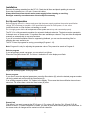
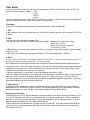
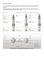
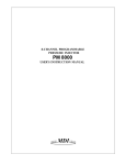
DF-12
ORDERCODE D2060
Congratulations!
You have bought a great, innovative product from DAP Audio.
The DAP Audio DF-12 brings excitement to any venue. Whether you want simple plug-&-play action or a
sophisticated show, this product provides the effect you need.
You can rely on DAP Audio, for more excellent audio products.
We design and manufacture professional audio equipment for the entertainment industry.
New products are being launched regularly. We work hard to keep you, our customer, satisfied.
For more information: [email protected]
You can get some of the best quality, best priced products on the market from DAP Audio.
So next time, turn to DAP Audio for more great audio equipment.
Always get the best -- with DAP Audio !
Thank you!
DAP Audio
DAP Audio DF-12 Product Guide
Warning..…...................................................................................…………………………………………..
Safety-instructions………………………………………………………………………………………….….
Operating Determinations…………………………………………………………………………………….
2
2
3
Description..…..............................................................................……….…………………………………
Features………………………………………………………………………………….………………….….
Overview Front side..…………………………………………………………………………………....…….
Overview Back side..…………………………………………………………………………………….…….
4
4
4
5
Installation..................................................................……………………………..…………………………
6
Set Up and Operation.....................................................................……..…………………………….……
Menu Functions………..………………………………………………………………………..……….…….
MIDI..……….……...……….…….……….……..……….……..……….……..……….……..……….…..….
6
7
9
Frequency Chart..................................................................……………………………..………………….
10
Preset Table..................................................................……………………………..…………………….…
11
Connection Cables..............................….......................................………..………….…….………….…..
12
Maintenance………..............................….......................................………..………….…….………….…..
Replacing the Fuse........................................................................…………………….…………………
13
13
Troubleshooting………..............................…................................………..………….…….………….…..
13
Product Specifications.................................................................……………….…….…………………..
14
1
WARNING
CAUTION!
Keep this system away from rain and moisture!
FOR YOUR OWN SAFETY, PLEASE READ THIS USER MANUAL CAREFULLY
BEFORE YOUR INITIAL START-UP!
SAFETY INSTRUCTIONS
Every person involved with the installation, operation and maintenance of this system has to:
be qualified
follow the instructions of this manual
CAUTION! Be careful with your operations.
With a dangerous voltage you can suffer
a dangerous electric shock when touching the wires!
Before you initial start-up, please make sure that there is no damage caused by transportation. Should there
be any, consult your dealer and do not use the system.
To maintain perfect condition and to ensure a safe operation, it is absolutely necessary for the user to follow
the safety instructions and warning notes written in this manual.
Please consider that damages caused by manual modifications to the system are not subject to warranty.
This system contains no user-serviceable parts. Refer servicing to qualified technicians only.
IMPORTANT:
The manufacturer will not accept liability for any resulting damages caused by the non-observance of
this manual or any unauthorized modification to the system.
•
•
•
•
•
•
•
•
•
•
•
•
•
•
•
•
Never let the power-cord come into contact with other cables! Handle the power-cord and all
connections with the mains with particular caution!
Never remove warning or informative labels from the unit.
Never use anything to cover the ground contact.
Do not insert objects into air vents.
Do not connect this system to a dimmerpack.
Do not switch the system on and off in short intervals, as this would reduce the system’s life.
Do not open this device. Risk: hazardous radiation exposure.
Do not run the output of any amplifier channel, back into another channel’s input.
Do not connect (parallel or series) an amplifier output with any other amplifier output.
Only use system indoor, avoid contact with water or other liquids.
Avoid flames and do not put close to flammable liquids or gases.
Always disconnect power from the mains, when system is not used. Only handle the power-cord by
the plug. Never pull out the plug by tugging the power-cord.
Make sure you don’t use the wrong kind of cables or defective cables.
Make sure that the signals into the mixer are balanced, otherwise hum could be created.
Make sure you use DI boxes to balance unbalanced signals; All incoming signals should be clear.
Make sure that the available voltage is not higher than stated on the rear panel.
2
•
•
•
•
•
•
•
•
•
•
•
•
•
•
•
•
•
Make sure that the power-cord is never crimped or damaged. Check the system and the power-cord
from time to time.
Always operate the unit with the AC ground wire connected to the electrical system ground.
Connecting amplifier outputs to oscilloscopes or other test equipment, while the amplifier is in
bridged mode, may damage both the amplifier and test equipment.
Do not drive the inputs with a signal level bigger, than required to drive the equipment to full output.
In system setup, the amplifier's output power must be 50%-100% more than the loaded
loudspeakers rated power.
Please turn off the power switch, when changing the power cord or signal cable, or select the input
mode switch.
In typical use, Please set the volume to 0dB position.
Sometimes, when you want to send one signal to more than one amplifier, you should use a signal
distributor.
Extreme frequency boosts in connection with a high input signal level may lead to overdriving your
equipment. Should this occur, it is necessary to reduce the input signal level by using the INPUT
control.
To emphasize a frequency range, you don’t necessarily have to move its respective sliding control
upward; try lowering surrounding frequency ranges instead. This way, you avoid causing the next
piece of equipment in your sound path to overdrive. You also preserve valuable dynamic reserve
(“headroom”)
For replacement use fuses of same type and rating only.
Prevent distortion! Make sure that all components connected to the DF-12 have sufficient power
ratings. Otherwise distortion will be generated because the components are operated at their limits.
Avoid ground loops! Always be sure to connect the power amps and the mixing console to the same
electrical circuit to ensure the same phase!
If system is dropped or struck, disconnect mains power supply immediately. Have a qualified
engineer inspect for safety before operating.
If the system has been exposed to drastic temperature fluctuation (e.g. after transportation), do not
switch it on immediately. The arising condensation water might damage your system. Leave the
system switched off until it has reached room temperature.
Repairs, servicing and electric connection must be carried out by a qualified technician.
WARRANTY: Till one year after date of purchase.
OPERATING DETERMINATIONS
If this system is operated in any other way, than the one described in this manual, the product may suffer
damages and the warranty becomes void.
Any other operation may lead to dangers like short-circuit, burns, electric shock, etc.
You endanger your own safety and the safety of others!
Improper installation can cause serious damage to people and property !
3
Description of the device
Features
The DF-12 is a professional Feedback Eliminator:
• The DF-12 effectively avoids any occurring feedbacks in your amplifying system
• 4 different Monitor Modes: OFF, Parametric EQ, Auto Mode, Vocal Mode.
• 12 automatically controlled feedback frequencies per channel
• Connection via balanced XLR-sockets or jacks
• Total real-time MIDI control
• 16 x 2 backlight LCD Display
Overview
Fig. 1
1) LCD Display
2) Parameter / Push Jogwheel: Adjust the parameters
3) Filter Mode
4) CH R / Couple
5) Store / MIDI
6) Filter / SEL: Sequence & Filter button. Press once to enter Filter (12 filters) and twice to enter
Sequence (10 Channels)
7) CH L
8) Bypass: This button allows you to instantly compare the original sound (Display shows BYP) with the
equalized sound (Display shows GEQ)
9) Power Switch
4
Fig. 2
DF-12 DESCRIPTION REAR PANEL:
10) IEC Connector + Fuse
11) AC Voltage Selector 115V/230V
12) Midi Out
13) Midi Thru
14) Midi In
15) XLR Output 2
16) TRS Output 2
17) Input Level –20dB / + 4dB
18) TRS Input 2
19) XLR Input 2
20) TRS Output 1
21) XLR Output 1
22) Input Level –20dB / + 4dB
23) TRS Input 1
24) XLR Input 1
Fig. 3
25) Clip LED: for Left / Right Input / Output indication
26) P: indicates the Program. You can select between P1 - P10.
27) CH: Adjust the Left / Right Channel
28) EQ: EQ-On means all filters are on; EQ-off means Auto & single are not affected; BYPA means all filter
effects are not functioning because you are in Bypass mode.
29) FILT: indicates the Filter. You can select between FILT1 – FILT12
30) PEQ: 4 Available modes: OFF, PEQ (parametric EQ), AUTO and SING (single)
31) SV: This reminds the user that the editable parameters are ready to be saved and stored in the memory,
by blinking slowly every 2 seconds. Press the STORE-button once and it will blink every second.
If you press the STORE-button again, the SV indication in the display will disappear.
5
Installation
Remove all packing materials from the DF-12. Check that all foam and plastic padding is removed.
Screw the equipment into a 19" rack. Connect all cables.
Always disconnect from electric mains power supply before cleaning or servicing.
Damages caused by non-observance are not subject to warranty.
Set Up and Operation
Before plugging the unit in, always make sure that the power supply matches the product specification
voltage. Do not attempt to operate a 120V specification product on 240V power, or vice versa.
Install this device on a flat surface, not bending or curved.
Do not supply power before all components of the system are set up and connected properly.
The DF-12 is a fully parametric equalizer for automatic feedback reduction. The device can be operated in
2-channel mono or stereo-mode. 12 equalizer filters are available per channel. They can either be adjusted
manually or automatically via two auto-functions.
If you do not need all equalizer filters for suppressing feedback, you can use the remaining filter for
adjusting the room acoustics etc.
The DF-12 has 10 programs for saving your settings (Program 1-10).
Note: Program 0 is only for adjusting the parameter values. They cannot be saved on Program 0.
Select a program
If you have already saved a program, you can select it as follows:
Press the Filter Select-button (6). The colon (:) behind the P in the display must flash.
Adjust the desired program via the jog-wheel.
Save a program
If you want to save the adjusted parameters, press the Store-button (5), select the desired program-number
via the jog-wheel and confirm with the Store-button (5).
If an existing program is edited, „SV“ flashes in the display. This means that the modification has not been
stored yet. For storing them, press the Store-button (5) twice.
Stereo-Link
First define if you want to operate the DF-12 mono L, R or stereo LR. Use the CH L (7) and CH R (4)
buttons to select. To select or deselect LR Mode, you have to press both buttons (4+7) at the same time. In
the stereo-mode, all changes will be carried out at both channels.
6
Filter Select
Press the Filter Select-button (6) and select the desired filter-number via the jog-wheel (2). The DF-12 is
able to work with 4 different modes: 1. OFF
2. PEQ
3.AUTO
4. SING
You can independently set the Filter mode for each of the 12 filters. In order to meet flexible & complicated
signal processing, you may combine all 4 modes in one sequence.
Filter Mode
Press the Filter Mode-button and select the desired filter mode via the jog-wheel (2).
1. OFF
In this mode the filter is not used and turned off. If you want to activate the filter you can select PEQ, AUTO
or SING.
2. PEQ
This mode is a fully adjustable parametric filter.
First press and then turn the jog-wheel (2) in order to change: Parameter Freq (20 Hz to 20 kHz),
Gain (-48 to +16 dB)
Band (1/60 octave to 2 octaves)
Fine (-9/60 to +10/60)
In Band mode you can select a bandwidth of 2 octaves by turning the jog-wheel clockwise, until the display
reads 120 1/60.
In Fine Mode, you can fine-tune the frequency bands in 1/60 octave steps (20Hz – 20Khz).
3. AUTO
The Auto filter will work with 2 both modes: SINGLE & AUTO Mode. In order to sense feedback, the DF-12
will divide the entire frequency bandwidth in 1/60 octave steps.
New feedbacks are automatically detected and suppressed with the smallest possible bandwidth and cut.
The first Auto-filter „locks“ the feedback frequency, while the remaining auto-filters keep searching for other
feedbacks and suppress them. When all auto-filters are occupied, the filter with the oldest setting will be
released in order to keep searching for new feedbacks.
In speech transmission, you may want to lower the feedback sensitivity to –9dB.
This will compress the feedback. On the other hand if you increase the sensitivity (-3dB) it will become more
stable, but it will be slower in detecting a feedback signal. We advise you to use AUTO Mode when you
work with portable microphones, because they always have changeable feedback frequencies. In this way,
upcoming feedbacks can be suppressed effectively.
4. SING (Single)
Feedbacks in certain frequencies are automatically detected and suppressed with the smallest possible
bandwidth and cut. Afterwards, the filter is locked. The adjusted frequency will be permanently monitored
and doesn’t change any more. The DF-12 automatically adjusts the bandwidth and cut.
Adjusting the sensitivity
The sensitivity of the DF-12 can be adjusted for both auto-modes. In its original setting the sensitivity is set
to–6 dB. This sensitivity is perfect for most applications. If you set the sensitivity to –3 dB, the sensitivity is
lowered, i.e. the device reacts more slowly to upcoming feedbacks. If you set the sensitivity to –9 dB, the
highest sensitivity is reached (e.g. for speech transmission).
Press and hold the Filter Mode-button (3) and press the jog-wheel (2). The display shows SENS: and the
current sensitivity. Adjust the desired sensitivity via the jog-wheel (2) and quit the mode by pressing the
Filter Mode button (3).
7
Bypass-function
By pressing the Bypass-function, all adjustments will be deactivated. The display shows EQ-OF. This
function allows you to instantly compare the original signal with the modified parametric equalizer (PEQ)
signal.
Note: When you activate the Bypass-function, all suppressed feedback frequencies are deactivated.
Danger of immediate feedbacks!
Restoring the original settings
Press and hold the Filter Select-button (6) and the Store-button (5) while turning the device off and on again.
The original settings are loaded.
Note: All adjustments will be deleted.
Please see the Preset Table (See Page 11) for all the presets.
MIDI-settings
Press and hold the Bypass-button (8) and press the Store-button (5) in order to enter the Midi-menu.
Press the Bypass-button (8) in order to navigate the Midi-menu.
Channel select (CH-XX)
Select the desired Midi-channel via the jog-wheel (2). When you want to switch off the Midi-function, select
CHOFF.
Omni-mode
In the Omni-mode, the DF-12 sends and receives all data on all Midi-channels.
Adjusting the receive/send options
Display
Control 0
Control 1
Control 2
Control 3
Control 4
Modes
The DF-12 ignores all controller data, nothing is received or sent
Controller data is received but not sent.
Controller data is sent but not received.
Controller data is received and sent.
Similar to Control 3, but with program selection
Adjusting the program changes
Display
Program 0
Program 1
Program 2
Program 3
Modes
Program changes will not be sent.
Program changes will be received, but not sent.
Program changes will be sent, but not received.
Program changes will be received and sent.
Overwrite programs
The Save On-function enables quick storing of programs coming from the Midi-controller to the DF-12.
If the Save On-function is activated, the DF-12 receives Controller #28 data. The current adjustments will be
directly saved on the program number corresponding to the controller value.
Note: The transmission and storage will not require a confirmation. Already existing programs will
immediately be overwritten. Switch this device off as soon as you do not need it anymore.
Save Off. The DF-12 does not react to Controller #28 data.
The device automatically switches to Save Off when switched off.
8
SysEx-Dump
With this function, you can transmit the memory content between 2 DF-12’s or to another Midi Sys-Ex
compatible Sequencer or computer.
Please note: a received Sys-Ex Dump can delete all settings of a device. If you do not wish that a device
accidentally receives Sys-Ex data, switch it off or adjust another Midi-channel.
Connect the Midi Out-socket of the sending device with the Midi In-socket of the receiving one.
Set the receiving device to SYS RXD and press the Store-button. The device is ready for receiving.
Set the sending device to SYS TXD. Press the Store-button as soon as the receiving device is ready for
receiving.
MIDI
Able to transmit & receive REAL TIME transmission data through MIDI connection.
MIDI IN
Any MIDI data sent to the DF-12 (sequencer, MIDI footswitch, etc.) is received via the MIDI IN jack. For
example, if you wish to use the DF-12 as an effect device for a guitar rack, you can connect the MIDI In jack
to a MIDI footswitch, which allows for selecting program presets. Another possibility, if your footswitch
allows it, is to control the gain of every frequency band separately with an expression pedal. Per expression
pedal you can only control 1 frequency band or master volume. For more details see the MIDI
Implementation Chart. If your rack includes another MIDI effect device (a multi-effect processor), the data
sent from the footswitch can be routed via the DF-12 MIDI THRU jack to your multi-effect processor.
MIDI THRU
The MIDI THRU jack is used to loop through incoming data, i.e. any control received at the MIDI In of the
DF-12 will be transmitted via the MIDI THRU jack to other MIDI devices or instruments.
MIDI OUT
The MIDI OUT jack allows for transmitting MIDI data that originate from the DF-12.
MIDI Application with DF-12
With its built-in interface the DF-12 can be integrated into any MIDI system, where it transmits and receives
both program change and controller change information to perform program changes via MIDI from a
sequencer or any other MIDI devices.
Fig. 3
9
Frequency Chart
DISPLAY -9/60 -8/60 -6/60 -4/60 -2/60
20Hz
25Hz
22.8
23
23.5
24
24.5
32Hz
28.6
28.9
29.6
30.2
30.9
40Hz
36.2
36.6
37.5
38.3
39.2
50Hz
45.5
46
47
48
49
63Hz
57
58
59
60
62
80Hz
72.4
73
75
77
78
100Hz
91
92
94
96
98
125Hz
114
115
118
120
123
160Hz
144
146
150
153
157
0.20KHz
0.25KHz
0.32KHz
0.40KHz
0.50KHz
0.63KHz
0.80KHz
1.00KHz
1.25KHz
1.60KHz
182
228
286
362
455
572
724
910
1138
1443
184
230
289
366
460
578
732
920
1150
1460
188
235
296
375
470
591
749
940
1175
1495
192
240
302
383
480
604
766
960
1200
1530
196
245
309
392
490
617
783
980
1225
1565
2.0KHz
2.5KHz
3.2KHz
4.0KHz
5.0KHz
6.30KHz
8.0KHz
10.0KHz
12.5KHz
16.0KHz
20KHz
1820
2275
2858
3618
4550
5715
7235
9100
11375
14425
18200
1840
2300
2890
3660
4600
5780
7320
9200
11500
14600
18400
1880
2350
2955
3745
4700
5910
7490
9400
11750
14950
18800
1920
2400
3020
3830
4800
6040
7660
9600
12000
15300
19200
1960
2450
3085
3915
4900
6170
7830
9800
12250
15650
19600
ISO
20
25
31.5
40
50
63
80
100
125
160
+2/60 +4/60 +6/60 +8/60 +10/60
20.5
21
21.5
22
22.5
25.7
26.3
27
27.6
28.3
32.4
33.2
34.1
34.9
35.8
41
42
43
44
45
51
53
54
55
57
65
66
68
70
71.5
82
84
86
88
90
103
105
108
110
113
129
132
136
139
143
164
168
172
176
180
200
250
315
400
500
630
800
1000
1250
1600
205
257
324
410
513
647
820
1025
1285
1640
210
263
332
420
526
664
840
1050
1320
1680
215
270
341
430
539
681
860
1075
1355
1720
220
276
349
440
552
698
880
1100
1390
1760
2000 2050
2100
2150
2200
2500 2565
2630
2695
2760
3150 3235
3320
3405
3490
4000 4100
4200
4300
4400
5000 5130
5260
5390
5520
6300 6470
6640
6810
6980
8000 8200
8400
8600
8800
10000 10250 10500 10750 11000
12500 12850 13200 13550 13900
16000 16400 16800 17200 17600
20000
10
225
283
358
450
565
715
900
1125
1425
1800
2250
2825
3575
4500
5650
7150
9000
11250
14250
18000
Preset Table
Preset
1
Left
Right
Filter 1
Filter 2
Filter 3
Filter 4
Filter 5
Filter 6
Filter 7
Filter 8
MONO: 9 single shot filters attenuate room resonance before 3 automatic filters destroy variable feedback
SING
SING
SING
SING
SING
SING
SING
SING
SING
SING
SING
SING
SING
SING
SING
SING
2
Left
Right
2xMONITOR as Feedback Destroyer only:7 single shots/5 automatic filters for most monitor setup
SING
SING
SING
SING
SING
SING
SING
SING
SING
SING
SING
SING
SING
SING
3
Left
Right
MONO AUTO PILOT: 12 filters per channel constantly chase and destroy feedbacks
AUTO
AUTO
AUTO
AUTO
AUTO
AUTO
AUTO
AUTO
AUTO
AUTO
AUTO
AUTO
AUTO
AUTO
Filter 9
Filter 10
Filter 11
Filter 12
SING
SING
AUTO
AUTO
AUTO
AUTO
AUTO
AUTO
AUTO
AUTO
AUTO
AUTO
AUTO
AUTO
AUTO
AUTO
AUTO
AUTO
AUTO
AUTO
AUTO
AUTO
AUTO
AUTO
AUTO
AUTO
AUTO
AUTO
4
Couple
STEREO PARAMETRIC EQ: Preset with 12 ISO frequencies, all set to 1/3 octave, gain +0dB
125Hz
160Hz
200Hz
250Hz
315Hz
500Hz
630Hz
800Hz
§KHz
1.25KHz
1.6KHz
5
Couple
STEREO PARAMETRIC EQ: Preset with 12 ISO frequencies, all set to 2/3 octave, gain +0dB
40Hz
63Hz
100Hz
160Hz
250Hz
400Hz
630Hz
1KHz
1.6KHz
2.5KHz
4KHz
6.3KHz
6
Left
Right
23MONO: Sample monitoring, left for handheld (lead) microphone(s), right for fixed (backing) ones
SING
SING
SING
AUTO
AUTO
AUTO
AUTO
SING
SING
SING
SING
SING
AUTO
AUTO
AUTO
AUTO
PEQ
PEQ
PEQ
PEQ
PEQ
PEQ
PEQ
PEQ
7
Left
Right
MONO PARAMETRI and SINGLE SHOT FILTERS: A good start for fixed (backing) ones
SING
SING
SING
SING
SING
SING
SING
SING
SING
SING
SING
SING
SING
SING
PEQ
PEQ
PEQ
PEQ
PEQ
PEQ
PEQ
PEQ
SING
SING
SING
SING
SING
8
Couple
SING
SING
STEREO FOH EQ: providing 4 parametric EQ (low roll in filter and 2), plus 8 single shot filters
PEQ
PEQ
PEQ
SING
SING
SING
SING
40Hz
80Hz
10ct.
Channels are coupled; changes on one channel are valid for both channels.
-8dB
-4dB
9
Left
Right
MONO FREE
SING
SING
SING
SING
SING
SING
SING
SING
SING
SING
SING
SING
SING
SING
AUTO
AUTO
AUTO
AUTO
PEQ
PEQ
PEQ
PEQ
PEQ
PEQ
10
Couple
STEREO FREE
SING
SING
SING
SING
SING
SING
SING
AUTO
AUTO
PEQ
PEQ
que
11
Connection Cables
Take care of the connector cables, always holding them by the connectors and avoiding knots and twists
when coiling them: This gives the advantage of increasing their life and reliability, which is always to your
advantage.
Periodically check that your cables are in good condition, that they are correctly wired and that all their
contacts are perfectly efficient: a great number of problems (faulty contacts, ground hum, discharges, etc.)
are caused entirely by using unsuitable or faulty cables.
Headphones
Unbalanced mono 1/4” jack plug
Balanced mono 1/4” jack plug
Compensation of interference with balanced connections
12
Maintenance
The DF-12 equalizer requires almost no maintenance. However, you should keep the unit clean. Disconnect
the mains power supply, and then wipe the cover with a damp cloth. Do not immerse in liquid.
Keep connections clean. Disconnect electric power, and then wipe the audio connections with a damp cloth.
Make sure connections are thoroughly dry before linking equipment or supplying electric power.
Replacing a Fuse
Power surges, short-circuit or inappropriate electrical power supply may cause a fuse to burn out. If the fuse
burns out, the product will not function whatsoever. If this happens, follow the directions below to do so.
1. Unplug the unit from electric power source.
2. Insert a flat-head screwdriver into a slot in the fuse cover. Gently pry up the fuse cover.
3. Remove the used fuse. If brown or unclear, it is burned out.
4. Insert the replacement fuse into the holder where the old fuse was. Reinsert the fuse cover. Be sure to
use a fuse of the same type and specification. See the product specification label for details.
Troubleshooting
Dap Audio DF-12
This troubleshooting guide is meant to help solve simple problems.
If a problem occurs, carry out the steps below in sequence until a solution is found. Once the unit operates
properly, do not carry out following steps.
1. If the device does not operate properly, unplug the device.
2. Check the power from the wall, all cables etc.
3. If all of the above appears to be O.K., plug the unit in again.
4. If you are unable to determine the cause of the problem, do not open the equalizer, as this may damage
the unit and the warranty will become void.
5. Return the equalizer to your Dap Audio dealer.
13
Product Specifications
Model: DAP Audio DF-12
Power supply: 230 VAC, 50 Hz
Power consumption: 10 W
Inputs: XLR or balanced 1/4" jack
Nominal Operating Level: -20 dB to +4 dB
Max. input level: +16 dB at +4 dB nominal level, +2 dB at -20 dB nominal level
Input impedance: 40 balanced, 20 unbalanced
Outputs: XLR or balanced 1/4" jack
Max. output level: +16 dB at +4 dB nominal level, +2 dB at -20 dB nominal level
Output impedance: 66 balanced, 33 unbalanced
Frequency range: 20 Hz - 20 kHz
THD %: <0.06%
S/N-ratio: 98 dB, 20 Hz - 20 kHz
Crosstalk: -95 dB, 20 Hz - 20 kHz
MIDI-Interface: 5-pin DIN-socket IN/OUT/THRU
Converters: 24-bit Sigma-Delta, 64/128-times over-sampling
Sampling rate: 48 kHz
Dimensions: 482 x 152 x 45 mm (LxWxH)
Weight: 3 kg
Design and product specifications are subject to change without prior notice.
14
2005 Dap Audio.