1
Q MODEL
DISPENSER
Q160/290/300
Service
Manual
Thank you for selecting a Manitowoc Dispenser, the dependability leader in ice making equipment and related
products. With proper care and maintenance, your new Manitowoc Dispenser will provide you with many years
of reliable and economical performance.
This manual is updated as new information and models are released.
Visit our website for the latest manual. www.manitowocice.com
Part Number 80-1389-3
6/04
Safety Notices
Procedural Notices
Installation and start-up of this equipment should be
done by a qualified service technician.
When using or servicing a Q Model Dispenser, be sure
to read the procedural notices in this manual. These
notices supply helpful and important information.
When using or servicing a Q Model Dispenser, be sure
to pay close attention to the safety notices in this
manual. Disregarding the notices may lead to serious
injury and/or damage to the dispenser.
Throughout this manual, you will see the following
types of safety notices:
WARNING
Text in a Warning box alerts you to a potential
personal injury situation. Be sure to read the Warning
statement, and then proceed carefully.
CAUTION
Text in a Caution box alerts you to a situation in
which you could damage the dispenser. Be sure to
read the Caution statement, and then proceed
carefully.
CAUTION
Proper care and maintenance are essential for troublefree operation of your Manitowoc Dispenser.
Read and understand this manual. It contains valuable
care and maintenance information. If you encounter
problems not covered by this manual, feel free to
contact Manitowoc Ice, Inc. We will be happy to
provide assistance.
Throughout this manual, you will see the following
types of procedural notices:
NOTE: Text set off as a Note provides you with
simple, but useful, extra information.
Important
Important boxes serve two functions.
They call the operator’s attention to important
information.
They also provide the service technician with
information that may help perform a procedure
more efficiently. Disregarding this information may
slow down the work.
WARNING
Personal Injury Potential
Do not operate equipment that has been misused,
abused, neglected, damaged, or altered/modified from
that of original manufactured specifications.
Table of Contents
Table of Contents
Section 1 – Troubleshooting
Model/Serial Number Location..............................................................................................................................1-1
Model Numbers Covered in Manual .....................................................................................................................1-1
Warranty Information ............................................................................................................................................1-2
Equipment Overview...............................................................................................................................................1-3
Room Key Card Activation ....................................................................................................................................1-4
Coin Operated Activation ............................................................................................................................... 1-4
Ice Does Not Dispense When Rocking Chute is Depressed.......................................................................... 1-5
Dispenser Crushes Ice as it Dispenses ...................................................................................................................1-7
Ice Continues to Dispense or Dispenses by Itself..................................................................................................1-7
Section 2 – Equipment Specifications
Disassembling the Dispenser Parts
For Cleaning (Door Removal) ................................................................................................................................2-1
Cleaning the Drain Pan...........................................................................................................................................2-2
Disassembling the Rocking Chute/Door................................................................................................................2-3
Re-Installing the Paddle Wheel Guard .................................................................................................................2-6
Disassembling the Dispenser Parts for Bin Cleaning
(Agitator and Paddle Wheel Removal)..................................................................................................................2-7
Removal of the Gearmotor .....................................................................................................................................2-9
Gearmotor Shaft Seal Replacement ......................................................................................................................2-10
Section 3 – Electrical
Non-Adjustable Timer with Test Pins ........................................................................................................... 3-1
Non-Adjustable Timer ............................................................................................................................................3-2
Adjustable Timer.....................................................................................................................................................3-3
Adjusting the Coin Mechanism Timer ..................................................................................................................3-4
Adjusting the Coin Mechanism for Canadian Coins ...........................................................................................3-4
Wiring Diagrams
QPA-310, QPA-160, QFA-291 .........................................................................................................................8-1
QRA-340, QRA-164 Card Operated ...............................................................................................................8-9
QCA-330, QCA-163 Coin Operated................................................................................................................8-13
i
Table of Contents
THIS PAGE INTENTIONALLY LEFT BLANK
ii
Section 1
Troubleshooting
Troubleshooting
This manual is a reference guide for the
owner/operator, service agent and installer of this
equipment. Please read this manual before
installation or operation of the machine. If you
encounter a problem, first consult the Trouble
shooting Guide or Adjustments sections of this
manual. If you cannot correct the problem, call your
Manitowoc Service Agent, Distributor or the Factory.
Always have your model and serial number available
when you call.
Q1000 Ice Machines are not approved for use on a
Q-Model Dispenser.
Earthquake kits are available to secure the ice
machine to the dispenser and the dispenser to the
floor.
Adapter Kit
A 22’’ wide machine mounted to a 30’’ wide
dispenser requires an adapter kit
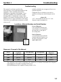
Locations of Model Number and Serial Number
Front of Dispenser
Label with Model Number and
Serial Number is located behind
the front panel, to the right of
the rocking chute.
Model
Number/
Serial
Number
Back of Dispenser
A second location for the Model
Number and Serial Number is on
the back of the dispenser, in the
upper right corner.
Dispensers Covered in This Manual
Series
Rocking Chute
Operated
Card Operated
Coin Operated
Glass Fill
Dispenser
Q160
QPA160
QRA164
QCA163
N/A
QPA310
QRA340
QCA330
N/A
Q300
N/A
N/A
N/A
QFA291
Q290
NOTE: These dispensers are designed to dispense both dice and half dice ice.
These dispensers may be used in conjunction with a Manitowoc ice machine for automatic fill of dispenser.
Q160 dispensers are capable of storing 120 lbs. of ice.
Q290/Q300 dispensers are capable of storing 180 lbs. of ice.
1-1
Troubleshooting
Section 1
Warranty Information
The packet containing this manual also includes
warranty information. Warranty coverage begins the
day your new dispenser is installed.
Important
Complete and mail the OWNER WARRANTY
REGISTRATION CARD as soon as possible to
validate the installation date.
If you do not return your OWNER WARRANTY
REGISTRATION CARD, Manitowoc will use the
date of sale to the Manitowoc Distributor as the first
day of warranty coverage for your new dispenser.
Warranty Coverage
The following Warranty outline is provided for your
convenience. For a detailed explanation, read the
warranty bond shipped with each product.
Contact your local Manitowoc representative or
Manitowoc Ice, Inc. if you need further warranty
information.
PARTS
Manitowoc warrants the dispenser against defects in
materials and workmanship, under normal use and
service, for three (3) years from the date of original
installation.
LABOR
Labor required to repair or replace defective
components is covered for three (3) years from the date
of original installation.
EXCLUSIONS
The following items are not included in the dispenser’s
warranty coverage:
1. Normal maintenance, adjustments and cleaning as
outlined in this manual.
1-2
2. Repairs due to unauthorized modifications to the
dispenser or the use of non-standard parts without
prior written approval from Manitowoc Ice, Inc.
3. Damage caused by improper installation of the
dispenser, electrical supply, water supply or
drainage, or damage caused by floods, storms, or
other acts of God.
4. Premium labor rates due to holidays, overtime, etc.;
travel time; flat rate service call charges; mileage
and miscellaneous tools and material charges not
listed on the payment schedule. Additional labor
charges resulting from the inaccessibility of the
dispenser are also excluded.
5. Parts or assemblies subjected to misuse, abuse,
neglect or accidents.
6. Damage or problems caused by installation,
cleaning and/or maintenance procedures
inconsistent with the technical instructions provided
in this manual.
AUTHORIZED WARRANTY SERVICE
To comply with the provisions of the warranty, a
refrigeration service company, qualified and authorized
by a Manitowoc distributor, or a Contracted Service
Representative must perform the warranty repair.
NOTE: If the dealer the dispenser was purchased from
is not authorized to perform warranty service, contact
the Manitowoc distributor or Manitowoc Ice, Inc. for
the name of the nearest authorized service
representative.
Section 1
Troubleshooting
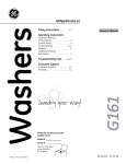
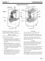
Equipment Overview
Agitator timer
Rocking chute
Removable
front panel
Agitator
Ice bin
Paddle
wheel
Gearmotor
Scrap ice
tray
Q300 Dispensers
Q160 Dispensers
The operation of the Q Series ice dispenser can be
divided into three main operations. They are
Dispenser Activation, Ice Pick-Up and Ice Delivery.
Ice Pick-Up
When the customer activates the dispenser, the
gearmotor inside the dispenser begins to turn.
Dispenser Activation
Dispenser activation can be accomplished with a
number of different mechanisms.
The gearmotor shaft is attached to the paddle wheel
inside the bin of the dispenser. As the paddle wheel
turns it picks up ice from the dispenser bin. The
paddle wheel will bring the pocket containing the ice
to the top of the travel area.
•
•
•
Rocking Chute (Push for Ice) Activation –User
pushes the Rocking Chute, which energizes a
microswitch. The energized microswitch engages
the gearmotor.
Room Key Card Activation – User places their
hotel room key card into a slot on the dispenser.
The room key card activates the microswitch. The
user then presses the Rocking Chute (Push for Ice)
for ice dispense. This action activates the
gearmotor.
Coin Operated Activation – User places one
quarter into dispenser. The quarter activates the
coin mechanism. The user then presses the
Rocking Chute (Push for Ice) for ice dispense.
This action activates the gearmotor.
Ice Delivery
When the paddle wheel pocket reaches the top of its
travel, the ice falls from the paddle wheel to the ice
chute opening of the dispenser bin. The bin chute
then directs the ice to the door assembly.
If the door closes before all the ice is dispensed, some
ice may be held back by the door assembly. If the
door is open, the ice will fall through the door and the
ice chute. The ice chute will direct the ice into the
customer’s container.
Model QFA-291 is equipped with an optional water
valve. When the water valve lever is pressed, water
flows through the system to the water valve nozzle.
1-3
Troubleshooting
Section 1
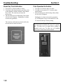
Room Key Card Activation
Coin Operated Activation
1. User places ice bucket under ice chute.
2. User places their hotel room key card into a slot
on the dispenser which is labeled “Insert Room
Key Card”. The room key activates the
microswitch.
3. The user then presses the Rocking Chute (Push
for Ice) for ice dispense. Pushing the ice chute
activates the gearmotor.
1. User places ice bucket under ice chute.
2. User places one quarter (U.S. currency only)
into dispenser.
3. The user then presses the Rocking Chute (Push
for Ice) for ice dispense.
The room key card must stay in the slot for the
microswitch to remain activated.
1-4
Pushing the ice chute activates the gearmotor.
Ice will dispense for up to one minute for each
25 cent activation per factory setting.
Important
Coin Operated Activation will accept U.S. quarters
only. No other coin is accepted and no change is
returned to the user. To allow use of Canadian
coins refer to instructions in this manual.
Section 1
Troubleshooting
WARNING
Unplug unit before servicing or cleaning.
Ice dispenser bin contains parts that can move at any
time and will cause injury if hands are in
the way.
WARNING
Unplug unit before servicing or cleaning.
The agitator is operated by a timer and can agitate at
anytime
Electric Shock Hazard.
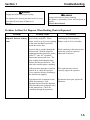
Problem: Ice Does Not Dispense When Rocking Chute is Depressed.
Problem
There is power to the
dispenser, however nothing
runs.
Possible Cause
To Correct
If no power is present, check the
The dispenser is plugged in with
cord and plug of the dispenser,
power to the receptacle. With a
meter, check to see if power is getting Replace cord set if wire is broken.
to the white and black cord wires
inside the electric box.
Is power able to conduct through the
microswitch? With the dispenser
unplugged and the ohm meter probes
on the “C” and “NC” terminals,
depress the microswitch lever. The
mere reading should display ohms.
Release the microswitch lever. The
ohm value should register continuity.
Check continuity at the microswitch,
replace the switch or repair the
connection if defective.
If the gearmotor attempts to start but
fails to do so, check the capacitor.
Use a capacitor checker according to
the instructions supplied.
If the capacitor does not test
correctly, replace the capacitor.
If gearmotor fails to attempt to start,
check the gearmotor. First,
disconnect power from the dispenser.
Then disconnect the gearmotor wires
in the junction box. Check for
continuity through the gearmotor.
If gearmotor tests open, replace the
gearmotor.
1-5
Troubleshooting
Section 1
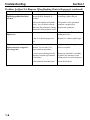
Problem: Ice Does Not Dispense When Rocking Chute is Depressed. (continued)
Problem
The gearmotor runs, but the
dispensing paddle wheel does
not turn.
Dispenser runs but does not
dispense ice.
Dispenser runs, ice does not
dispense but does congeal ice
into a large ball.
1-6
Possible Cause
To Correct
Remove the paddle wheel pin. Is
this pin broken, damaged, or
missing?
If the paddle wheel pin is broken
or missing, replace the pin.
Remove the agitator and paddle
wheel. Are you able to turn the
shaft from the gearmotor without
turning the motor armature itself?
The gearbox of the gearmotor
contains a stripped gear.
Replace the gearmotor.
Is there any ice in the bin?
If the ice is not sufficient, add
additional to bin.
Is the ice in the bin proper size
ice?
Replace ice with acceptable type.
The agitation timer should be
checked. See Section 3 for
proper checkout procedure.
Adjust or replace the agitation
timer as required.
Is excess water running into the
dispenser from the top mounted
ice machine?
Repair top mounted ice machine
to reduce the amount of water
falling on the ice in the dispenser.
Is the bin drain clean and open?
Clean the bin drain.
Section 1
Troubleshooting
Problem: Dispenser Crushes Ice as it Dispenses
Problem
Dispenser crushes ice as it
dispenses.
Possible Cause
To Correct
The ice in the bin is not the
proper size and type?
Replace ice with acceptable.
Is the ice being used a full size
piece of ice, i.e., are cubes full,
not shallow, etc.?
Adjust ice machine to make a
good, complete, not hollow piece
of ice.
Problem: Ice Continues to Dispense or Dispenses by Itself
Problem
Possible Cause
Is the agitation timer set
properly?
Timer should agitate for two
seconds every four hours.
Is the ice door opening fully
when the dispenser operates?
The ice door should open a
minimum of 1.5 in. (3.8 cm).
Does ice continue to dispense
after the cup has been pulled
away?
Does the gearmotor continue to
run during this time?
Does the ice dispense by itself
without anyone around the
dispenser?
Does the dispenser do this at
regular intervals?
To Correct
Adjust or replace timer if
necessary. See Section 3
“Component Disassembly”.
Adjust door to minimum or larger
opening.
Microswitch may be sticking.
Check and clean the microswitch
and linkage to the microswitch.
Replace microswitch if necessary.
Check the agitation timer. Adjust
the timer to two seconds on time
and four hours off time. Also
check to see if timer has a short.
1-7
Troubleshooting
Section 1
THIS PAGE INTENTIONALLY LEFT BLANK
1-8
Section 2
Component Disassembly
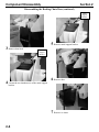
Disassembling the Dispenser Parts
For Cleaning
WARNING
Unplug unit before servicing or cleaning.
The agitator is operated by a timer and can agitate at
anytime.
Electric Shock Hazard.
Dispenser
Front
Panel
1 Shut off water to ice machine.
Black rubber
holes
Catch
Hook
3 Hold the front panel of the dispenser on both
sides and tilt the panel forward. The front panel
will be resting on the catch hooks at the bottom
of the panel.
2
4 QFA-291 ONLY - Disconnect water line at the
Locate a cylindrical object, such as a ballpoint
pen with a cap on the pen.
front panel “quick disconnect” fitting.
Insert the pen into the left and right black rubber
holes in the top of the front panel of the
dispenser.
This action releases the two clips which hold the
dispenser front panel in place.
While applying pressure on the pen, pull the
front panel forward slightly, so the clip in the
panel does not snap back into place.
2-1
Component Disassembly
Disassembling the Dispenser Parts
For Cleaning (continued)
Section 2
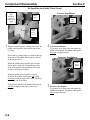
Removing the Drain Pan
Dispenser
Front
Panel
Catch
Hook
1 The drain pan is visible when the front panel of
the dispenser is removed.
5 Lift the front panel off the catch hooks and set the
panel aside.
2 Slide the drain pan forward.
3 Remove scrap ice if any scrap ice has
accumulated.
2-2
Section 2
Component Disassembly
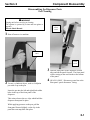
Disassembling the
Rocking Chute/Door
Removing the Drain Pan
(continued)
WARNING
Unplug unit before servicing or cleaning.
Electric Shock Hazard.
Drain Pan
1 Remove the front panel as described on pages
4-1 and 4-2.
4 Remove the inner drain pan. Clean the inner
drain pan with sanitizing solution. (See page
4-9.)
5 After cleaning, place inner drain pan back into
outer drain pan.
6 Slide drain pan back into place.
2 Remove outer bracket.
2-3
Component Disassembly
Section 2
Disassembling the Rocking Chute/Door (continued)
Metal
Support
Bracket
5 Remove metal support bracket.
3 Remove door lock.
Metal
Support
Bracket
4 Loosen the two thumbscrews of the metal support
6 Remove door.
bracket.
7 Remove ice chute.
2-4
Section 2
Component Disassembly
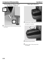
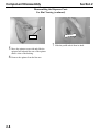
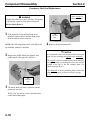
Disassembling the Rocking Chute/Door (continued)
Paddle
wheel
guard
Paddle
wheel
guard
Retainer
8 Remove the two thumb screws from the plastic
paddle wheel guard retainer.
10
Pull the stainless steel paddle wheel guard
from the slot that is cut into the chute…
Paddle
wheel
guard
Paddle
wheel
guard
Retainer
9 Remove the paddle wheel guard retainer
11
…and remove the paddle wheel guard
retainer.
2-5
Component Disassembly
Section 2
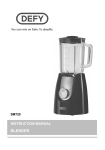
Re-Installing the Paddle Wheel Guard
Cylinder
hinge
Welded to
Front of
Paddle wheel
Guard
Correct Installation
Slot in
Chute
Paddle
wheel
guard
Paddle
wheel
guard
(front)
1 When re-assembling the rocking chute/door, the
paddle wheel guard is placed in the slot in the
ice chute.
Notice that a cylinder hinge is welded to the top
front side of the paddle wheel guard, as shown
in the picture above.
2 Correct Installation:
If you press your finger forward against the
paddle wheel guard, the paddle wheel guard
does not swing back open.
Incorrect Installation
Paddle
wheel
guard
When the paddle wheel guard is placed in the
slot in the ice chute, the cylinder hinge on the
front of the paddle wheel guard faces forward,
as shown in the picture above.
When the paddle wheel guard is correctly
installed, the paddle wheel guard will swing
outward toward the front of the chute, allowing
ice to flow out of the chute.
If incorrectly installed, the paddle wheel guard
will not swing outward and ice delivery is
blocked.
2-6
3 Incorrect Installation:
If you press your finger forward against the
paddle wheel guard, the paddle wheel guard
does swing back open.
Section 2
Component Disassembly
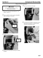
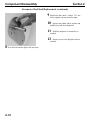
Disassembling the Dispenser Parts
For Bin Cleaning
WARNING
Unplug unit before servicing or cleaning.
Paddle
wheel
pin
Ice dispenser bin contains moving parts that can move
at any time and will cause injury if hands are in the
way.
Paddle
wheel
pin
handle
3 …Then remove the paddle wheel pin by firmly
rotating the pin and pulling upward.
1 Inside the dispenser, rotate the agitator arm so
the paddle wheel pin handle is pointing up,
toward the ceiling.
Paddle
wheel
pin
handle
Paddle
wheel
hub
4 Push the agitator bar toward the back of the bin
until agitator is free of the paddle wheel hub.
2 Un-clip the hand-removable paddle wheel pin
from the agitator…
2-7
Component Disassembly
Section 2
Disassembling the Dispenser Parts
For Bin Cleaning (continued)
Bushing
5 Move the agitator to one side and slide the
agitator forward until the rear of the agitator
shaft is clear of the bushing.
6 Remove the agitator from the bin area.
2-8
7 Slide the paddle wheel from its shaft.
Section 2
Component Disassembly
Removal of the Gearmotor
WARNING
Unplug unit before servicing or cleaning.
Electric Shock Hazard.
5 Pull removal pins out to the right.
1 Remove the front panel from dispenser. (See
pages 4-1 and 4-2.)
2 Remove paddle wheel pin, agitator, and paddle
wheel. (See pages 4-5 and 4-6.)
6 As soon as the second pin is removed, be sure to
hold onto the gearmotor as it slides forward.
Then place the gearmotor aside.
Gearmotor
Wire
3 Unplug the gearmotor wire.
Remove
Pins
4 Turn the two removal pins toward you as shown
in photo.
2-9
Component Disassembly
Section 2
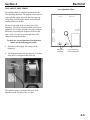
Gearmotor Shaft Seal Replacement
Oil Seal Retainer
Marks Topside Of
Bin Insulator Plate
WARNING
Unplug unit before servicing or cleaning. The agitator
is operated by a timer and can agitate at anytime
Electric Shock Hazard.
1 If the dispenser is top mounted with an ice
machine, remove the ice machine front panel.
Most will allow access to the bin.
NOTE: The following photos show a bin that is not
top-mounted with an ice machine.
2 Remove the paddle wheel pin, agitator, and
paddle wheel. (See pages 4-5 and 4-6.)
Bin
insulator
plate
4 Remove the bin insulator plate.
CAUTION
It is important to know which side of the bin insulator
plate you are accessing, the topside or the underside.
The topside of the bin insulator plate can be noted by
an approximately two-inch square of oil seal retainer
welded to the top of the bin insulator plate. (As
shown in Step 4 above.)
The underside of the bin insulator plate is where the
shaft seal is located. (As shown in Step 5 on page
5-2.)
Bin
insulator
plate
3 The motor shaft seal can be replaced with the
gearmotor in or out.
With a 7/16” nut driver, remove the three bolts
on the bin insulator plate.
2-10
Section 2
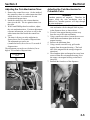
Component Disassembly
Gearmotor Shaft Seal Replacement (continued)
Shaft seal marks the
underside of bin
insulator plate
Shaft seal
5 Locate the shaft seal on the underside of the bin
insulator plate.
6 Using a screwdriver, pry out the shaft seal, then
throw the shaft seal away.
CAUTION
Know which side of the shaft seal you are accessing,
the convex side or the concave (ridge) side.
Snap in the new seal with the concave (ridge) side
down. Otherwise the seal will not work and the
dispenser will leak.
7 With the convex side of the shaft seal facing up
(and the concave, ridge side facing down), snap
the new shaft seal onto the bin insulator plate.
CONVEX SIDE
(FRONT OF SHAFT SEAL)
CONCAVE SIDE
(RIDGE SIDE…BACK
OF SHAFT SEAL)
CAUTION
Preventive maintenance note:
Replace the motor shaft seal once a year.
2-11
Component Disassembly
Section 2
Gearmotor Shaft Seal Replacement (continued)
9 Replace the three bolts. Using a 7/16” nut
driver, tighten a quarter turn past tight.
10
Replace the paddle wheel, agitator and
paddle wheel pin in the dispenser.
11
Refill the dispenser or restart the ice
machine.
12
Restore power to the dispenser and ice
machine.
8 Press the bin insulator plate back into place.
2-12
Section 3
Electrical
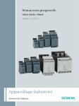
Agitation Timer
121$'-867$%/(7,0(5:7(673,16
7KHQHZWLPHULVHTXLSSHGZLWKWHVWSLQV7KLV
DOORZV\RXWRWHVWWKHWLPHUE\UHPRYLQJWKHMXPSHU
EHWZHHQWKHWZRSLQV1RQDGMXVWDEOHWLPHUVZLWK
WHVWSLQVPXVWEHZLUHGDVVKRZQEHORZ
:LWK7HVW3LQV
:LWKRXW7HVW3LQV
7KHDJLWDWLRQWLPHULVVWDQGDUGHTXLSPHQWIRUWKH
IORRUVWDQGLQJGLVSHQVHU7KHSXUSRVHRIWKHWLPHULV
WRSHULRGLFDOO\DJLWDWHWKHLFHLQWKHELQWRSUHYHQW
FRQJHDOLQJ1RQDGMXVWDEOHWLPHUVZLWKWHVWSLQVDUH
XVHGRQDOOFXUUHQWSURGXFWLRQPRGHOV
7KHWLPHULVQRQDGMXVWDEOHDQGLVVHWWRDJLWDWHWKH
LFHIRUWKUHHVHFRQGVHYHU\WKUHHDQGRQHKDOIKRXUV
$FWLYDWLQJWKHGLVSHQVHUZLOOUHVHWWKHWLPHU$IWHU
KRXUVRIQRQXVHWKHWLPHUZLOOHQHUJL]HWKH
GLVSHQVHUPRWRU
7RFKHFNIRUFRUUHFWIXQFWLRQRIWKHDJLWDWLRQ
WLPHUXVHWKHIROORZLQJSURFHGXUH
7KHDJLWDWLRQWLPHULVORFDWHGDWWKHIURQWRIWKH
GLVSHQVHURQWKHOHIWVLGHRIWKHLFHFKXWH
5HPRYHWKHMXPSHUEHWZHHQWKHWZRSLQV
7KHWLPHUZLOOF\FOHHYHU\VHFRQGV
,IWKHWLPHUGRHVQRWF\FOHHYHU\VHFRQGV
UHSODFHWKHWLPHU
0DNHVXUHWRUHSODFHMXPSHUWRSLQVDIWHU
WHVWLQJ
CAUTION
1HYHU RSHUDWH LQ ZLWK MXPSHU UHPRYHG 'DPDJH
ZLOORFFXU
&RUUHFW:LULQJ
6HHQH[WSDJHLIZLULQJRQWKHPDFKLQHLVLQFRUUHFW
7(673,16
$1'-803(5
7202725
72/,1(
72/,1(
,&(',63(16(
6:,7&+
:+,7(
12
1&
7202725
&200
%/$&.
%/8(
<(//2:
3-1
Electrical
5H:LULQJ3URFHGXUH
$ZLULQJFKDQJHPXVWEHPDGHLIWKHH[LVWLQJWLPHU
RQWKHGLVSHQVHULVZLUHGZLWKWKH\HOORZZLUHIURP
WKHWLPHUURXWHGWRWKHFRPPRQVLGHRIWKHLFH
GLVSHQVHVZLWFK
'LVFRQQHFWSRZHUWRWKHXQLW
5HPRYHWKHEODFNDQG\HOORZZLUHVDWWDFKHG
WRWKHFRPPRQWHUPLQDORIWKHLFHGLVSHQVH
VZLWFK
&XWWKH\HOORZDQGEODFNZLUHZKHUHLW
LQVHUWVLQWRWKHIHPDOHWHUPLQDOFRQQHFWRU
6WULSWKH\HOORZDQGEODFNZLUHLQVXODWLRQ
EDFNDQGFULPSDQLQVXODWHGIHPDOHVSDGH
FRQQHFWRURQWKHHQGRIHDFKZLUH
&RQQHFWWKHEODFNZLUHWRWKHFRPPRQVLGH
RIWKHLFHGLVSHQVHVZLWFK
&RQQHFWWKH\HOORZZLUHWRWKH1&WHUPLQDO
RQWKHLFHGLVSHQVHVZLWFK
5HFRQQHFWSRZHUWRWKHXQLW
3-2
Section 3
Section 3
Electrical
121$'-867$%/(7,0(5
7KHDJLWDWLRQWLPHULVVWDQGDUGHTXLSPHQWIRUWKH
IORRUVWDQGLQJGLVSHQVHU7KHSXUSRVHRIWKHWLPHULV
WRSHULRGLFDOO\DJLWDWHWKHLFHLQWKHELQWRSUHYHQW
FRQJHDOLQJ1RQDGMXVWDEOHWLPHUVDUHXVHGRQDOO
FXUUHQWSURGXFWLRQPRGHOV
7KHWLPHULVORFDWHGLQWKHHOHFWULFDOER[RIWKH
GLVSHQVHU7KHWLPHULVQRQDGMXVWDEOHDQGLVVHWWR
DJLWDWHWKHLFHIRUWKUHHVHFRQGVHYHU\WKUHHDQGRQH
KDOIKRXUV$FWLYDWLQJWKHGLVSHQVHUZLOOUHVHWWKH
WLPHU$IWHUKRXUVRIQRQXVHWKHWLPHUZLOO
HQHUJL]HWKHGLVSHQVHUPRWRU
7RFKHFNIRUFRUUHFWIXQFWLRQRIWKHDJLWDWLRQ
WLPHUXVHWKHIROORZLQJSURFHGXUH
'LVFRQQHFWDQGUHDSSO\OLQHYROWDJHWRWKH
GLVSHQVHU
7KHGLVSHQVHUPRWRUZLOOHQHUJL]HIRUVHFRQGV
DIWHUSRZHULVUHDSSOLHGWKHQF\FOHRII
7KHDJLWDWLRQWLPHULVORFDWHGDWWKHIURQWRIWKH
GLVSHQVHURQWKHOHIWVLGHRIWKHLFHFKXWH
1RQ$GMXVWDEOH7LPHU
0DOH6OLGH
7HUPLQDOV
6FUHZ$WWDFKLQJ
7LPHUWR'LVSHQVHU
3-3
Electrical
Section 3
$'-867$%/(7,0(5
7KHDJLWDWLRQWLPHULVVWDQGDUGHTXLSPHQWIRUWKH
IORRUVWDQGLQJGLVSHQVHU7KHSXUSRVHRIWKHWLPHULV
WRSHULRGLFDOO\DJLWDWHWKHLFHLQWKHELQWRSUHYHQW
FRQJHDOLQJ
7KHWLPHULVORFDWHGLQWKHHOHFWULFDOER[RIWKH
GLVSHQVHU7KHWZRGLDOVRQWKHWLPHUVKRXOGEHVHW
WRDJLWDWHWKHLFHIRUWZRVHFRQGHYHU\IRXUKRXUV
$FWLYDWLQJWKHGLVSHQVHUZLOOUHVHWWKHWLPHU$IWHU
KRXUVRIQRQXVHWKHWLPHUZLOOHQHUJL]HWKH
GLVSHQVHUPRWRU
7RFKHFNWKHDJLWDWLRQWLPHU
XVHWKHIROORZLQJSURFHGXUH
3ODFHDVPDOOVFUHZGULYHULQWKHDGMXVWPHQWGLDO
PDUNHG³2))7,0(´VHHLOOXVWUDWLRQDWULJKW
*HQWO\WXUQWKHDGMXVWPHQWGLDOFRXQWHU
FORFNZLVHXQWLOWKHGLDOVWRSV<RXZLOOEH
WXUQLQJWKHGLDOVRLWSRLQWVWRWKH³20,1´
SRVLWLRQ
'RQRWXVHWKHGLVSHQVHUIRUPLQXWHV:LWKLQ
WKDWWLPHSHULRGWKHDJLWDWRUZLOOWXUQ,IWKH
DJLWDWRUGRHVQRWWXUQUHSODFHWKHWLPHU
7RUHVHWWKHDJLWDWLRQWLPHU
8VHWKHIROORZLQJSURFHGXUH
:LWKDVPDOOVFUHZGULYHUJHQWO\WXUQERWKGLDOV
FRXQWHUFORFNZLVHXQWLOWKH\VWRS<RXZLOOEH
WXUQLQJWKHGLDOVRLWSLQWVWRWKH³20,1´
SRVLWLRQZKLFKVWDQGVIRU2PLQLPXP
7XUQWKH³217,0(´OHIWGLDOIURPWKH³´WR
WKH³´IRUWZRVHFRQGVRIDJLWDWLRQ
7XUQWKH³2))7,0(ULJKWGLDOIURPWKH³´
WRWKH³´VRDJLWDWLRQZLOOEHJLQDSSUR[LPDWHO\
HYHU\IRXUKRXUV
3-4
7KHDJLWDWLRQWLPHULVORFDWHGLQWKHHOHFWULFDOER[DW
WKHIURQWRIWKHGLVSHQVHU
7KHGUDZLQJVKRZVWKHSRVLWLRQRIWKHGLDOVZKHQ
WKHWLPHULVVHWFRUUHFWO\
217,0(
2))7,0(
6HFRQGVRIDJLWDWLRQ
+RXUVRIIEHWZHHQDJLWDWLRQ
DGMXVWPHQWGLDO
DGMXVWPHQWGLDO
0DOHVOLGH
6FUHZDWWDFKLQJ
WHUPLQDOV
WLPHUWRGLVSHQVHU
127('LDOVRQDFWXDODJLWDWLRQWLPHUDUHQRW
PDUNHGZLWKQXPEHUVRQO\VPDOOQRWFKHV
Section 3
Electrical
Adjusting the Coin Mechanism Timer
5HPRYHWKHFRQWUROER[FRYHU2QWKHLQVLGHRI
WKHFRQWUROER[WKHUHLVDZKLWHLQVWUXFWLRQODEHO
ZKLFKVKRZVKRZWRVHWLQWHUYDOVIRUFRLQ
PHFKDQLVPGLVSHQVHWLPHV
,QVLGHWKHFRQWUROER[WKHFRLQPHFKDQLVP
WLPHULVWRWKHOHIW7KHLFHDJLWDWLRQWLPHULVWR
WKHULJKW
:LWKDVPDOO3KLOOLSVKHDGVFUHZGULYHUDGMXVW
WKHFRLQPHFKDQLVPWLPHU)RUWLPHUDGMXVWPHQW
UHIHUHQFHLQIRUPDWLRQVHHEHORZRUUHIHUWRWKH
ZKLWHLQVWUXFWLRQODEHOLQVLGHWKHFRQWUROER[
FRYHU
7KHWLPHULVIDFWRU\VHWDWWKHPLGSRLQWDV
VKRZQDERYHIRUVHFRQGVRIGLVSHQVHWLPH
7KHDGMXVWPHQWSRWFDQEHVHW
FRXQWHUFORFNZLVHIRUDVORZDVVHFRQGVRI
GLVSHQVHWLPH
7KHDGMXVWPHQWSRWFDQEHVHWFORFNZLVHIRUDV
KLJKDVVHFRQGVRIGLVSHQVHWLPH
&RLQ0HFKDQLVP
7LPHU
Adjusting the Coin Mechanism for
Canadian Coins
Important
&DQDGLDQ TXDUWHUV DUH PDJQHWLF 7KHUHIRUH WKH
PDJQHW LQVLGH WKH FRLQ PHFKDQLVP PXVW EH
UHPRYHG VR &DQDGLDQ TXDUWHUV ZLOO GURS WKURXJK
WKHFRLQPHFKDQLVP
5HPRYHWKHIURQWSDQHORIWKHGLVSHQVHU7KH
FRLQPHFKDQLVPFDQEHFKDQJHGZKLOHLQSODFH
LQWKHGLVSHQVHUGRRUDVVKRZQDERYH
3LYRWWKHFRLQPDJQHWKRXVLQJVHFWLRQDZD\
IURPWKHUHVWRIWKHFRLQPHFKDQLVP
8VLQJDVPDOOVFUHZGULYHUORRVHQWKHVHWVFUHZ
ZKLFKKROGVDQDOXPLQXPSODWHLQWKHFRLQ
PDJQHWKRXVLQJ
5HPRYHWKHDOXPLQXPSODWH
8VLQJDPHWDOVFUHZGULYHUWLSSXOORXWWKH
PDJQHWIURPWKHPDJQHWKRXVLQJ7KHEDFN
VLGHRIWKHPDJQHWKDVWKHVWURQJHUPDJQHWLF
DWWUDFWLRQ
7KHDOXPLQXPSODWHDQGPDJQHWKDYHQRZEHHQ
UHPRYHGIURPWKHFRLQPDJQHWKRXVLQJ3LYRW
WKHHPSW\FRLQPDJQHWKRXVLQJVHFWLRQEDFN
LQWRSODFH
5HLQVWDOOWKHIURQWGRRURIWKHGLVSHQVHU
3-5
Electrical
Section 3
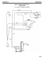
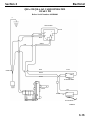
Wiring Diagrams
43$43$4)$
3+
%HIRUH6HULDO1XPEHUV
25$1*(
*5281'
%/$&.
12
<(//2:
1&
&200
,&(',63(16(
6:,7&+
$*,7$7,21
7,0(5
<(//2:
:+,7(
<(//2:
%/$&.
25$1*(
%/8(
7(50,1$/675,3
32:(5
&25'
%/$&.
02725
69
3-6
Section 3
Electrical
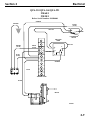
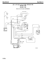
43$43$4)$
3+
6HULDO1XPEHUVWR
25$1*(
%/$&.
*5281'
12
<(//2:
1&
&200
,&(',63(16(
6:,7&+
$*,7$7,21
7,0(5
<(//2:
:+,7(
<(//2:
%/$&.
25$1*(
%/8(
%/$&.
02725
3-7
Electrical
Section 3
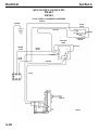
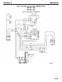
43$43$4)$
3+
$IWHU6HULDO1XPEHUV
25$1*(
*5281'
%/$&.
<(//2:
12
1&
,&(',63(16(
6:,7&+
$*,7$7,21
7,0(5
<(//2:
:+,7(
%/$&.
%/8(
%/$&.
32:(5
&25'
02725
69$
3-8
&200
Section 3
Electrical
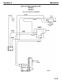
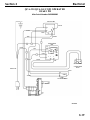
43$43$4)$
%HIRUH6HULDO1XPEHUV
25$1*(
*5281'
%/$&.
+=
12
<(//2:
1&
&200
,&(',63(16(
6:,7&+
$*,7$7,21
7,0(5
%52:1
+=
<(//2:
:+,7(
+=
<(//2:
%/8(
+=
25$1*(
%/8(
7(50,1$/675,3
%/$&.
02725
69
3-9
Electrical
Section 3
43$43$4)$
6HULDO1XPEHUVWR
25$1*(
*5281'
<(//2:
%/$&.
+=
12
1&
$*,7$7,21
7,0(5
,&(',63(16(
6:,7&+
<(//2:
%52:1
+=
:+,7(
+=
<(//2:
%/8(
+=
25$1*(
%/8(
02725
69
3-10
&200
Section 3
Electrical
43$43$4)$
$IWHU6HULDO1XPEHUV
25$1*(
*5281'
%/$&.
+=
12
<(//2:
1&
&200
,&(',63(16(
6:,7&+
$*,7$7,21
7,0(5
%52:1
+=
<(//2:
:+,7(
+=
<(//2:
%/8(
+=
25$1*(
02725
69$
3-11
Electrical
Section 3
45$45$&$5'23(5$7('
3+
3+
%HIRUH6HULDO1XPEHUV
*
$*,7$7,217,0(5
*
<
%/$&.
%/8(
%/8(
1
:+,7(
25$1*(
/
%52:1
%/$&.
25$1*(
12
1&
<(//2:
&200
,&(',63(16(6:,7&+
02725
3,1.
12
25$1*(
1&
.(<&$5'6:,7&+
69
3-12
Section 3
Electrical
45$45$&$5'23(5$7('
3+
3+
$IWHU6HULDO1XPEHUV
*
$*,7$7,217,0(5
*
<
%/$&.
%/8(
%/8(
1
:+,7(
25$1*(
/
%52:1
%/$&.
25$1*(
12
1&
<(//2:
&200
,&(',63(16(6:,7&+
02725
3,1.
12
25$1*(
1&
.(<&$5'6:,7&+
69$
3-13
Electrical
Section 3
45$45$&$5'23(5$7('
3+
%HIRUH6HULDO1XPEHUV
*
$*,7$7,217,0(5
<(//2:
%/$&.
:+,7(
%/8(
25$1*(
%/$&.
%/$&.
25$1*(
32:(5&25'
12
1&
<(//2:
&200
,&(',63(16(6:,7&+
02725
3,1.
12
25$1*(
1&
.(<&$5'6:,7&+
69
3-14
Section 3
Electrical
45$45$&$5'23(5$7('
3+
%HIRUH6HULDO1XPEHUV
*
$*,7$7,217,0(5
<(//2:
%/$&.
:+,7(
%/8(
32:(5&25'
25$1*(
%/$&.
%/$&.
25$1*(
12
1&
<(//2:
&200
,&(',63(16(6:,7&+
02725
3,1.
12
25$1*(
1&
.(<&$5'6:,7&+
69$
3-15
Electrical
Section 3
4&$4&$&2,123(5$7('
3+
3+
%HIRUH6HULDO1XPEHU
*
$*,7$7,217,0(5
<
*
%
:
%/8(
25$1*(
%/8(
&2,10(&+$1,60
7,0(5
%52:1
1& 12
%
:
1
/
%
&20 0,1
0$;
:
1&
5('
%/$&.
3,1.
<(//2:
12
1&
&200
,&(',63(16(6:,7&+
02725
69
3-16
&20
&2,10(&+$1,60
6:,7&+
Section 3
Electrical
4&$4&$&2,123(5$7('
3+
3+
$IWHU6HULDO1XPEHU
*
$*,7$7,217,0(5
<
*
%
:
%/8(
25$1*(
%/8(
&2,10(&+$1,60
7,0(5
%52:1
1& 12
%
:
1
/
%
&20 0,1
0$;
:
1&
5('
&20
&2,10(&+$1,60
6:,7&+
%/$&.
3,1.
12
<(//2:
1&
&200
,&(',63(16(6:,7&+
02725
69$
3-17
Electrical
Section 3
4&$4&$&2,123(5$7('
3+
%HIRUH6HULDO1XPEHU
*
$*,7$7,217,0(5
<(//2:
%/$&.
:+,7(
%/8(
25$1*(
:+,7(
&2,10(&+$1,60
7,0(5
1& %/$&.
3,1.
12
3853/(
:+,7(
%/$&.
&20 0,1
5('
0$;
3853/(
5('
1&
12 &20
&2,10(&+$1,60
6:,7&+
3,1.
32:(5&25'
%/$&.
12
<(//2:
1&
&200
,&(',63(16(6:,7&+
<(//2:
02725
69
3-18
Section 3
Electrical
4&$4&$&2,123(5$7('
3+
After Serial Number 0405000000
*
$*,7$7,217,0(5
<(//2:
%/$&.
:+,7(
%/8(
25$1*(
&2,10(&+$1,60
7,0(5
1& %/$&.
3,1.
12
%/$&.
&20 0,1
0$;
3853/(
5('
1&
12 &20
&2,10(&+$1,60
6:,7&+
32:(5&25'
%/$&.
12
1&
<(//2:
&200
,&(',63(16(6:,7&+
02725
69$
3-19
MANITOWOC ICE, INC.
We reserve the right to make product
improvements at any time.
Specifications and design are subject to
change without notice.
2110 South 26th Street P.O. Box 1720
Manitowoc, WI 54221-1720
Phone: (920) 682-0161
Service Fax: (920) 683-7585
Web Site - www.manitowocice.com
2003 Manitowoc Ice, Inc.
Litho in USA


![User's Manual AH-160M Series [Hardware & Software]](http://vs1.manualzilla.com/store/data/006866992_1-bebe17d6e04075ac71fce0bfab0e4653-150x150.png)