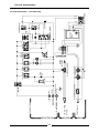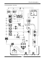
1
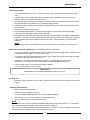
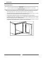
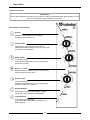
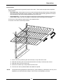
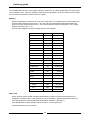
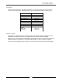
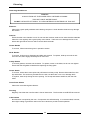
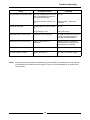
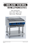
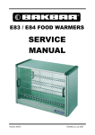
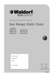
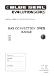
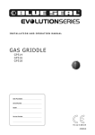
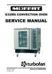
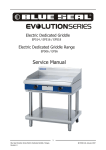
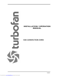
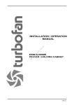
INSTALLATION / OPERATION
MANUAL
G32M CONVECTION OVEN
G32MS CONVECTION OVEN
F24824-15
MANUFACTURED BY
Moffat Limited
PO Box 10001
Christchurch
New Zealand
Ph:
(03) 389 1007
Fax:
(03) 389 1276
WORLD-WIDE BRANCHES
UNITED KINGDOM
Blue Seal
Units 6-7, Mount Street Business Park
Mount Street, Nechells
Birmingham B7 5QU
Ph:
(121) 327 5575
Fax:
(121) 327 9711
UNITED STATES
Moffat Inc
3765 Champion Blvd
Winston-Salem
North Carolina 27115
Ph:
(336) 661 0257
Fax:
(336) 661 9546
CANADA
Serve Canada
22 Ashwarren Road
Downview
Ontario M3J1Z5
Toll Free:800 263 1455
Ph:
(416) 631 0601
Fax:
(416) 631 0315
[email protected]
www.servecanada.com
www.moffat.com
NEW ZEALAND
Christchurch
Moffat Limited
PO Box 10-001
16 Osborne Street
Christchurch
Ph:
(03) 389 1007
Fax:
(03) 389 1276
Auckland
Moffat Limited
4 Waipuna Road
Mt Wellington
Auckland
Ph:
(09) 574 3150
Fax:
(09) 574 3159
AUSTRALIA
Victoria
Moffat Pty Limited
740 Springvale Road
Mulgrave, Melbourne
Victoria 3171
Ph:
(03) 9518 3888
Fax:
(03) 9518 3838
New South Wales
Moffat Pty Limited
3/142 James Ruse Drive, Rose Hill
PO Box 913, Smithfield
Sydney, N.S.W. 2142
Ph:
(02) 8833 4111
Fax:
(02) 8833 4133
Western Australia
Moffat Pty Limited
67 Howe Street
Osbourne Park
WA 6017
Ph:
(08) 9202 6820
Fax:
(08) 9202 6836
Queensland
Moffat Pty Limited
30 Prosperity Place
Geebung, Brisbane
Queensland 4034
Ph:
(07) 3630 8600
Fax
(07) 3630 8623
The reproduction or copying of any part of this manual by any means whatsoever is strictly forbidden unless authorized previously in
writing by the manufacturer.
In line with policy to continually develop and improve its products, Moffat Ltd. reserves the right to change the specifications and
design without prior notice.
© Copyright Moffat Ltd. November 2006.
Contents
Introduction .......................................................................................................... 2
Installation ............................................................................................................ 3
Before Connection
Supply Requirements
Location
Electrical Connection
Gas Connection
Water Connection
Before Use
Lighting Instructions
Reversing the Door
Specifications....................................................................................................... 7
Operation .............................................................................................................. 8
Description of Controls
Baking
Roast ‘n’ Hold
Oven Racks
Cooking Guide ................................................................................................... 12
Baking
Bake-Off
Roasting
Roast ‘n’ Hold
Cleaning and Maintenance................................................................................ 14
Trouble Shooting ............................................................................................... 15
Spare Parts ......................................................................................................... 16
Circuit Schematics............................................................................................. 18
Canada
UK
Non UK / Canada
Date Purchased................................................................. Serial No ..........................................................
Dealer............................................................................................................................................................
Service Agent ................................................................................................................................................
1
Introduction
We are confident that you will be delighted with your TURBOFAN OVEN, and it will become a most valued
appliance in your commercial kitchen.
A new oven can seem very complex and confusing at first glance. To ensure you receive the utmost
benefit from your new Turbofan, there are two important things you can do.
Firstly
Please read the instruction book carefully and follow the directions given. The time taken will be well
spent.
Secondly
If you are unsure of any aspect of the installation, instructions or performance of your oven, contact your
G32 dealer promptly. In many cases a phone call could answer your question.
This oven is designed to meet the technical safety and health standards of the United Kingdom, U.S.A.,
Europe, Canada, Australia and New Zealand.
Instructions to be followed in the event the user smells gas are to be posted in a prominent location. This
information shall be obtained by consulting the local gas supplier.
THIS APPLIANCE IS FOR PROFESSIONAL USE AND IS ONLY TO BE USED
BY QUALIFIED PEOPLE
CAUTION: When operating the oven the door surface will be hot.
FOR YOUR SAFETY
DO NOT store or use gasoline or other flammable vapours or liquids in the vicinity of this or
any other appliance.
Improper installation, adjustment, alteration, service or maintenance can cause
property damage, injury or death. Read the installation, operating and maintenance
instructions thoroughly before installing or servicing this equipment.
2
Installation
Installation Requirements
It is most important that this oven is installed correctly and that operation is correct
before use.
Installation shall comply with local electrical, gas, health and safety requirements.
This appliance must be installed in accordance with National installation codes and in addition, in
accordance with relevant National / Local codes covering gas and fire safety.
UNITED KINGDOM:
GAS SAFETY (Installation & Use)
REGULATIONS 1984 (Amendment 1990)
AUSTRALIA:
AS5601 / AG601 - 2000, Gas Installations Code
NEW ZEALAND:
NZS5261, Installation of Burning Appliances and Equipment
UNITED STATES:
ANSI 223.1 (Latest edition) National Gas Fuel Code
CANADA:
CAN/CGA -B149, Installation Codes for Gas Burning Appliances and
Equipment
Installations must be carried out by authorised persons only. Failure to install equipment to relevant
codes and manufacturers specifications in this section will void warranty.
The oven and its individual shutoff valve must be disconnected from the gas supply piping system
during any pressure testing of that system at test pressures in excess of 3.45 kPa / 34.5 mbar (0.5psi).
This oven must be electrically grounded in accordance with local codes.
Installation must allow for a sufficient flow of fresh air for the combustion air supply. Combustion air
requirements:
Natural Gas (G20-UK)
10m³/hr
Propane Gas (G31-UK)
9m³/hr
Components having adjustments protected (e.g. paint sealed) by manufacturer are only allowed to be
adjusted by an authorised service agent. They are not to be adjusted by the installation person.
Before Connection to Power and Gas Supplies
•
Remove all packing.
•
Check equipment and parts for damage. Report any damage immediately to the carrier and
distributor.
•
Remove protective plastic coating from the side panels.
•
Check that the following parts have been supplied with your oven:
4 x Leg assembly
4 x Oven racks
1 x Water inlet elbow (c/w washer)
•
Report any deficiencies to the distributor who supplied the oven.
•
Fit the legs to the oven or fit oven to manufacturers stand.
•
Check that the available power and gas supply is correct to that shown on the rating plate located
on the right -hand side panel.
Supply Requirements
Input Rating
(N.H.G.C.)
Natural Gas
LPG
Natural Gas - UK
(G20)
Propane - UK
(G31)
35 MJ/hr
(33,000 Btu/hr)
35 MJ/hr
(33,000 Btu/hr)
9.5 kW
(0.91 m³/hr)
9.5 kW
(0.67 kg/hr)
3
Installation
Supply Requirements (continued)
Natural Gas
LPG
Natural Gas - UK
(G20)
Propane - UK
(G31)
1.13 kPa
2.75 kPa
20 mbar
37 mbar
(4½” w.c.)
(11” w.c.)
Operating Pressure
0.85 kPa
(3.5” w.c.)
2.25 kPa
(9.0” w.c.)
10 mbar
35 mbar
Gas Connection
½” BSP Female
½” NPT Female (Canada only)
Supply Pressure
Electrical Connection
Cold Water Connection
½” BSP Female
220-240 Volts AC, 50Hz, 0.7A, 0.168kW, Single Phase
220 Volts AC, 60Hz, 0.7A, 0.168kW, Single Phase
110 Volts AC, 60Hz, 2.0A, 0.12kW, Single Phase
¾” B.S.P. (80psi maximum pressure)
Location
•
This oven must be installed in an area of adequate air supply. To ensure correct ventilation for the
motor and controls the following minimum installation clearances are to be adhered to:
Top
Rear
Left-hand side
Right-hand side
200mm / 8” (or 600mm / 24” from a combustible surface)
75mm / 3”
75mm / 3”
75mm / 3” (Fixed installations require at least 500mm (20”) clearance at
the right hand side for service accessibility.)
•
This oven must be fitted on supplied legs in all installations, unless installed on a manufacturers
stand.
•
Position the oven in its working position.
•
Use a spirit level to ensure oven is level from side to side and front to back. (If this is not carried
out, uneven cooking could occur). The legs used with bench/floor mounting or provided with
stands are adjustable and will require adjusting in levelling the unit.
•
The unit should be positioned such that the operating panel and oven shelves are easily reachable
for loading and unloading.
Important:
THE VENT LOCATED ON THE OVEN TOP MUST NEVER BE OBSTRUCTED.
•
Adequate ventilation is essential. DO NOT obstruct the air flow around the ventilation slots.
Electrical Connection
This oven is fitted with an approved power supply cord via an electrical junction box at the right hand
rear of the unit. Should changing of the cord be necessary then follow the instructions given below:
•
Remove right hand side panel to allow access to the terminal block and strain relief cable clamp.
•
The cable can be fitted through the small grommet and held by the cable clamp.
4
Installation
Gas Connection
•
A ½" BSP female elbow (½" N.P.T female - Canada only) is provided at the bottom rear of the
oven.
•
A restraint chain anchor has been provided above the gas connection point for fitment of a
restraint chain when a flexible gas line is fitted.
•
It is important that adequately sized piping run directly to the connection joint on the oven with as
few tees and elbows as possible to give maximum supply volume.
•
A suitable jointing compound which resists the break down action of LPG must be used on every
gas connection.
•
Check all connections for leakages.
•
Check appliance name plate on oven front right hand for correct orifice size and operating
pressure for the gas being installed, before operation.
•
The appliance combination gas valve is fitted with an internal regulator for adjusting the operating
pressure. To access, remove appropriately marked side service panel from bottom right side of
oven. Unscrew and remove regulator cap from gas valve. Adjust regulator to achieve stated
pressure.
NOTE:
Pressure test points are located behind this side service panel also at bottom right side of oven.
Water Connection - Optional (not required for main oven operation)
•
If the manual addition of water into the oven for humidification or steaming effect on baked product
is required, the unit’s water connection can be used.
•
A cold water supply should be fitted to the water inlet (¾” BSP hose connection) which is located
on the rear of the right hand side of the unit.
•
Alternately, a connection elbow and sealing washer is supplied with this unit for direct
connection of a ½” ID hose, and is recommended for easy installation and service.
•
Connect water supply - Max inlet pressure 80psi / 550kPa.
•
Turn on water supply to check for leaks.
Important:
MAXIMUM INLET WATER PRESSURE IS 550 kPa / 80 psi.
Before Use
•
Operate the oven for about 1 hour at 200°C (400°F) to remove any fumes or odours which may be
present.
Lighting Instructions
•
Set the thermostat temperature.
•
Automatic ignition will light the burner.
•
If not, turn the thermostat off, and wait 5 minutes before relighting.
•
The burner will cycle on/off to maintain the set temperature.
•
Turn the thermostat off to shut-down the burner.
NOTE:
If the burner is not cycling to maintain temperature the ignition system has locked out. To reset turn
the thermostat to the ‘off’ position. Wait 5 minutes before relighting.
If the flame is lost during operation the ignition system will try three times to re-establish the flame with
a 30 second delay between each try, before going into lockout.
5
Installation
Reversing the Door
Important:
THE FOLLOWING PROCEDURE SHOULD ONLY BE PERFORMED BY A QUALIFIED
SERVICEPERSON.
If desired, a left hand hinged oven door can be changed to a right hand hinged door (or vice versa).
•
While supporting the door, undo the door hinges from the oven. Remove the door.
•
The bottom right door catch plate should now be transferred to the top left of the oven (1), and the
top right door catch plate transferred to the bottom left of the oven (2).
•
Secure the door hinges and oven door to the right hand side of the oven door opening.
•
If alignment of the door is necessary, the five screws along the bottom of the oven can be
loosened, and the door moved a small amount to ensure that it is square with the oven. Tighten
the screws when the correct door position is attained.
•
If necessary the roller catches can be removed from the door (after removing handle on stainless
steel doors) to adjust height settings for correction of door catch operation.
1
2
6
Specifications
710
(28")
810
(32")
MWS
E
1
GAS
50
(2")
Front
E
510
(20")
350
(13¾")
205
(8")
1
MWS
900
(35½")
( 28")
28"
GAS
Side
70
(2¾")
(3½")
1
E
MWS
GAS
Plan
Natural Gas
LPG
Natural Gas - UK
(G20)
Propane - UK
(G31)
Input Rating
(N.H.G.C.)
35 MJ/hr
(33,000 Btu/hr)
35 MJ/hr
(33,000 Btu/hr)
9.5 kW
(0.91 m³/hr)
9.5 kW
(0.67 kg/hr)
Injector Size
Ø2.80 mm
Ø1.80 mm
Ø2.60 mm
Ø1.55 mm
Supply Pressure
1.13 kPa
(4½” w.c.)
2.75 kPa
(11” w.c.)
20 mbar
37 mbar
Operating Pressure
0.85 kPa
(3.5” w.c.)
2.25 kPa
(9.0” w.c.)
10 mbar
35 mbar
Gas Connection
½” BSP Female
½” NPT Female (Canada only)
Electrical Connection
Cold Water Connection
½” BSP Female
220-240 Volts AC, 50Hz, 0.7A, 0.168kW, Single Phase
220 Volts AC, 60Hz, 0.7A, 0.168kW, Single Phase
110 Volts AC, 60Hz, 2.0A, 0.12kW, Single Phase
¾” B.S.P. (550kPa / 80psi maximum pressure)
7
Operation
Operation Guide
Important:
Ensure that a clearance of 50mm (2”) from the oven ceiling is maintained when placing product on the
top shelf. This ensures correct operation of the oven.
Description of Controls
Power
Depress to switch power on or off (switch
illuminates when power is on).
Thermostat
Temperature range 50-320°C (120 - 600°F).
Indicator illuminates when the burner is cycling ON
to maintain set temperature.
Bake Timer
1 Hour bake timer.
(Indicator illuminates when “time up” (0) reached,
and buzzer sounds).
Roast ‘n’ Hold
Depress switch to activate ’Roast ’n’ Hold’ function.
(Switch illuminates when ON).
Roast Timer
3 Hour roast timer.
(Indicator illuminates when “time up” (0) reached).
Product is held at 75°C (165°F).
Steam Switch
Push switch to activate water injection. (Water
injects into oven while button is depressed).
Light Switch
Push switch to activate lights.
(Lights illuminate while button is latched in the
down position).
8
Operation
Baking
1. Turn power on
Power switch illuminates when it is depressed and latched in the down position.
2. Set thermostat to desired temperature
The heating indicator light will illuminate whenever the burner is cycling on to maintain the set
temperature.
Note:
If the burner is not cycling to maintain temperature the ignition system has locked out. To
reset turn the thermostat to the ‘off’ position.
If the flame is lost during operation the ignition system will try three times to re-establish the
flame with a 30 second delay between each try, before going into lockout.
3. Load oven
Once the oven is up the temperature, open the door and load the oven with product. Avoid
delays in loading the oven with the door open as this will delay the oven’s temperature
recovery.
Note:
The oven lights will illuminate when the door is opened.
4. Set bake timer to desired time
To set timer, turn knob clockwise to the required time. At any stage, the time can be adjusted
in either direction.
For settings less than 10 minutes, first set to greater setting, then turn down to the required
time period.
Note:
This 60 minute timer is completely independent of the oven control.
5. Water injection
To steam the oven while baking, push the steam switch on the control panel. We
recommend a 2-15 second injection period, according to product need, for this oven.
Keep switch depressed for required steam period.
6. Light
To view the product while baking, depress the light switch on the control panel. The lights will
stay on while the switch is latched in the down position.
7. Time up.
When the timer reaches 0 minutes the buzzer sounds and indicator illuminates.
To cancel the buzzer turn the timer to the off position.
8. Unload oven
Open the door and unload the oven .
Note:
The oven lights will illuminate when the door is opened.
9
Operation
Roast ‘n’ Hold
1. Turn power on
Power switch illuminates when it is depressed and latched in the down position.
2. Set thermostat to desired temperature
The heating indicator light will illuminate whenever the burner is cycling on to maintain the set
temperature.
Note:
If the burner is not cycling to maintain temperature the ignition system has locked out. To
reset turn the thermostat to the ‘off’ position.
If the flame is lost during operation the ignition system will try three times to re-establish the
flame with a 30 second delay between each try, before going into lockout.
3. Load oven
Once the oven is up the temperature, open the door and load the oven with product. Avoid
delays in loading the oven with the door open as this will delay oven temperature recovery.
Note:
The oven lights will illuminate when the door is opened.
4. Set roast timer to desired time
This 3 hour timer is electrically driven and is set by turning the timer knob in either direction to
the required time. The timer can be set when convenient, but will not start working until the
oven control is set and the Roast ’n Hold switch is depressed (switch illuminated).
5. Depress roast switch
Depress the Roast ’n Hold switch. The switch will illuminate and the timer will begin to count
down.
6. Water injection
To steam the oven while roasting, push the steam switch on the control panel. We
recommend a 2-15 second injection period, according to product need, for this oven.
Keep switch depressed for required steam period.
7. Light
To view the product while roasting, depress the light switch on the control panel. The lights
will stay on while the switch is latched in the down position.
8. Hold
When the timer reaches the hold position, the main oven thermostat is turned off and a
pre-set hold thermostat located behind the control panel will control the oven to keep the food
warm at serving temperature as long as required until the Roast ‘n Hold switch is turned off.
Note:
The hold light will illuminate when the timer reaches hold until the Roast ’n Hold switch is
turned off. The hold light may come on briefly when the Roast ’n Hold control is first switched
on until the oven heats up beyond the pre-set holding temperature.
10
Operation
Oven Racks
The oven is supplied with four general purpose oven racks. These racks incorporate two important
safety features:
•
Self Supporting: When fitted, the oven racks are self supporting and will not drop or angle down
when the racks are withdrawn during operation, when loading and unloading products on racks or
when attending to the product being cooked during it’s cook cycle.
•
Auto Supporting: The oven rack supports incorporate a special retaining tab which provides a
positive stop to each oven rack and stops it’s inadvertent removal during normal operation.
To fit the oven racks follow the steps shown in the diagram below.
To remove oven racks reverse the procedure.
1
2
4
3
5
1. Fit the oven rack, positioning the rack back stop on top of the rack runner.
2. Slide the rack along the runner and ensure that the front stop is under the rack runner.
3. Slide the rack to the rear of the oven.
4. Allow the rack back stop to drop below the rack runner.
5. The rack can now be pulled forward and loaded as required.
NOTE:
Components having adjustments protected (e.g. paint sealed) by manufacturer are only to be
adjusted by an authorised service agent. They are not to be adjusted by the user.
11
Cooking guide
This TURBOFAN oven will cook a greater quantity of food faster, at a lower temperature and more evenly
than an ordinary oven. As many excellent recipe books are published, it is not our intention to list recipes,
but to provide a temperature and time chart as a guide.
Baking
Select a temperature of about 20-30°C (35-55°F) lower than in a conventional oven and preheat oven
until the heating indicator light goes out. The oven has now reached the desired temperature and
trays of food may be placed in the oven. The oven will take four American trays (26" x 18") or eight
American half trays (18" x 13").
Use the racks supplied if American baking trays are not available.
FOOD
TEMP°C
TIME
Sponges
165
10-12 mins
Small Cakes
165
8-12 mins
Butter Cakes
160
35 mins
Fruit Loaf
150
40-50 mins
Macaroons
160
15-20 mins
Biscuits
140
12-20 mins
Shortbread
130
15-20 mins
Scones
200
10-12 mins
Madeira
165
35-50 mins
Bread
200
25-35 mins
Plain Fruit Cake
165
1-1½ hrs
Rich Fruit Cake
130
2-3 hrs
Gingerbread
140
35-50 mins
Baked Custard
130
50 mins
Souffle
165
25 mins
Rice Pudding
130
2-3 hrs
Puff
220
8-12 mins
Short
175
8-12 mins
Flakey
205
8-12 mins
Jam
185
12-20 mins
Fruit
185
35 mins
Pastry
Bake-Off
Frozen product (yeast, breads or butter based pastries) is placed on baking trays and put into a
refrigerator overnight to thaw. After proofing, the trays of breads or pastries are baked in this oven.
Oven temperature for yeast based products should be 190-220°C (340-355°F).
Oven temperature for butter based products should be 180°C (320-330°F).
A full load will bake in 20-25 minutes.
12
Cooking guide
Roasting
Set the oven temperature to 150-160°C (300-320°F). The hot air circulating in the oven reduces
moisture loss and shrinkage. Roasting times are reduced by approximately 20 minutes per kg.
MEAT
TIME per kg
Beef - Rare
Beef - Medium
30-40 min
40-50 min
Beef - Well Done
50-60 min
Veal
50-70 min
Lamb
30-40 min
Duck
50 min
Goose
50 min
Turkey
30-40 min
Chicken
- under 1kg
- over 1kg
50-65 min
40-50 min
Roast-’n’-Hold
This system will automatically cook food for a set time, then hold the oven at a preset temperature
indefinitely to maintain food at a serving temperature after cooking has been completed.
When the oven has reached the set temperature, place food in the oven, set roast cooking time and
depress the Roast ’n’ Hold button. The hold indicator will come on when cooking is complete.
To return to normal operation, push the Roast ‘n’ Hold switch again (switch will cease illuminating).
13
Cleaning
Cleaning Guidelines
Caution:
ALWAYS TURN OFF THE POWER SUPPLY BEFORE CLEANING.
THIS UNIT IS NOT WATER PROOF.
DO NOT USE WATER JET SPRAY TO CLEAN INTERIOR OR EXTERIOR OF THIS UNIT.
Exterior
Clean with a good quality stainless steel cleaning compound. Harsh abrasive cleaners may damage
the surface.
Interior
Ensure that the oven chamber is cool. Do not use wire brushes, steel wool or other abrasive materials.
Clean the oven regularly with a good quality oven cleaner. Take care not to damage the fan or the
tube at the right side of the oven which controls the thermostat.
Oven Racks
To remove, follow instructions given in operation section.
Side Racks
To remove, lift front top to disengage and slide rack forward. To replace, slide top rear slot in rack
onto rear stud, then engage front keyhole on front stud.
Lamp Glass
To remove glasses, unscrew anti-clockwise. To replace, screw in clockwise, but do not over tighten.
Ensure that the silk gasket is fitted before replacing the lamp glass.
Oven Seals
To remove, hold at their centre point and pull forward until they unclip. Remove side seals first, then
top and bottom. The seals may be washed in the sink, but take care not to cut or damage them.
To replace, have the lip facing the oven opening. Fit the top and bottom seals first, then the side
seals.
Oven Door Glass
Clean with conventional glass cleaners.
Venting
Regularly check that the oven flue tube is free of obstruction. The flue tube must NEVER be covered.
Lubrication
No lubrication is required by the user. Components are self-lubricating. It is recommended, however,
that a light coating of grease be used on the door catches to provide smooth operation.
14
Trouble-shooting
Fault
Possible Cause
The oven does not operate / start. The mains isolating switch on the
wall, circuit breaker or fuses are
“off” at the power board.
Remedy
Turn on.
The power switch on the oven is
off.
Depress switch. Switch will
illuminate.
Isolating valve on oven is turned
off.
Turn on.
No gas supply to unit.
Check gas supply.
Bake timer does not time down.
Bake timer not set correctly.
For settings less than 10 minutes,
first set to greater setting then
turn back to desired setting.
Roast timer does not time down
Roast ‘n’ Hold button not
depressed.
Depress Roast ‘n’ Hold button.
(Roast timer only operates when
Roast function is selected).
Oven light not illuminating.
Blown bulb.
Replace bulb.
No water injection / steam.
Water not turned on.
Turn water on at water supply.
Burner will not ignite.
NOTE: Components having adjustments protected (e.g. paint sealed) by manufacturer are only allowed
to be adjusted by an authorised service agent. They are not to be adjusted by an unauthorised
service person.
15
Spare parts
Replacement Part List
Controls
021473
021514
024774
020823
020849
023857
011760
011794
015822
021476
021515
011419
011983
015823
021472
021534
021535
021474
024773
018223
024802
003002
003434
013520
023216
013521
---------019369K
Power Switch (220-240V)
Power Switch (110V)
Thermostat
Knob - Thermostat / Bake Timer
Neon Indicator (220-240V)
Neon Indicator (110V)
Bake Timer
Buzzer (220-240V)
Buzzer (110V)
Roast ‘n Hold Switch (220-240V)
Roast ‘n Hold Switch (110V)
Roast ‘n Hold Timer (220-240V, 50Hz)
Roast ‘n Hold Timer (220-240V, 60Hz)
Roast ‘n Hold Timer (110V, 60Hz)
Roast ‘n Hold Timer Knob
Roast ‘n Hold Relay (220-240V)
Roast ‘n Hold Relay (110V)
Steam Switch
Light Switch
Hold Thermostat
Microswitch
Oven Lamp Glass
Silk Gasket
Oven Lamp Assembly - 40W Miniature Edison Screw (220-240V)
Oven Lamp Assembly - 40W Edison Screw (110V)
Oven Light Bulb (220-240V)
Oven Light Bulb (110V) - E26 40W
Over-temp Thermostat Kit (UK Only)
Motor
014672
015821
015598
Fan Motor (220-240V)
Fan Motor (110V)
Oven Fan
Steam System
020851
021617
021057
021526
021527
Water Solenoid (240V)
Water Solenoid (110V)
Spray Nozzle Assembly
Water Inlet Elbow
Washer
Ignition System
023025
023024
019370
015626
024851
SA1530
025071
024127
Ignition Box (220-240V - SIT)
Ignition Box (110V, USA/Canada - Fenwall)
Gas Control Valve (220-240V)
Gas Control Valve (25V)
Transformer (USA/Canada)
Complete Ignition Electrode Assembly
Flame Sensor Electrode
Spark / Earth Electrodes
16
Spare parts
Door
024784
024785
020082
020083
024809
017905
Door Seal (Side)
Door Seal (Top/Bottom)
Top Hinge
Bottom Hinge
Roller Catch
Door Bush
021468
024599
024844
002340
Door Handle (G32M)
Door Handle Bracket (G32M)
Door Outer Glass (G32M)
Door Inner Glass (G32M)
024713
023063
Door Handle (G32MS)
Door Glass (G32MS)
Racks
015575
015656
015168
Oven Side Rack - LH
Fan Baffle
Oven Rack
Gas Type Conversion Kits
025901
019379
019378
Natural Gas and LPG Conversion Kit
Natural Gas to Propane Gas Conversion Kit (UK Only)
Propane Gas to Natural Gas Conversion Kit (UK Only)
Stacking Kit
025739
Double Stacking Kit
17
ELECTRICAL
18
WATER
1/2" NPT MALE
10mm ID HOSE
(3/8 inch)
EARTH/GROUND
NEUTRAL
CONNECTIONS
4
2
GAS REGULATOR
(GREEN/YELLOW)
(BLACK)
(RED)
POWER
1
2
1
2
WATER
INJECTOR
LIGHTS
WATER SOLENOID
TIME
UP
1
3
GAS SOLENOIDS
2
1
NC NO
C
3
4
SPARK
1
2
5 7
6 8
HOLD
SENSOR
3
4
DOOR
1Hr TIMER WATER LIGHTS M'SWITCH
BUZZER
B
3
1
4
2
4
1
V1
TH
GND
S1
2
HEATING
HOLD
T'STAT
1
2
1
3Hr TIMER
6
3
IGNITION
BOX
V2
M
5
2
HOLD
3
HOLD
1
THERMOSTAT
WHITE
BLACK
BLUE
YELLOW
GAS
TRANSFORMER
Circuit schematics
Circuit Schematic - Canada Only
ELECTRICAL
19
WATER
1/2" BSP FEMALE
BRASS ADAPTOR
(1/8" BSP)
GREEN
YELLOW
BLUE
BROWN
CONNECTIONS
1
2
WATER
INJECTOR
LIGHTS
WATER SOLENOID
TIME
UP
1
2
GAS SOLENOIDS
2
1
3
1
4
NC NO
C
3
DOOR
1Hr TIMER WATER LIGHTS M'SWITCH
BUZZER
B
3
1
EARTH/GROUND
NEUTRAL
L1
2
4
2
GAS REGULATOR
OVER 1
TEMP
POWER
3
4
5 7
6 8
SENSOR
SPARK
1
2
HOLD
4
2
4
1
M
5
2
HOLD
2
HEATING
HOLD
T'STAT
1
2
1
T12
T11
T10
T9
T14
T13
T2
T1
T4
T3
IGNITION
T6
BOX
T5
T15
T16
ROAST TIMER
6
3
3
HOLD
1
THERMOSTAT
Circuit schematics
Circuit Schematic - UK Only
GAS
ELECTRICAL
20
WATER
1/2" BSP FEMALE
10mm ID HOSE
(3/8 inch)
GREEN
YELLOW
BLUE
BROWN
CONNECTIONS
4
2
GAS REGULATOR
1
2
1
2
WATER
INJECTOR
LIGHTS
WATER SOLENOID
TIME
UP
1
3
GAS SOLENOIDS
2
1
3
4
5 7
6 8
SPARK
1
2
HOLD
SENSOR
3 60Hz
50Hz 4
NC NO
C
DOOR
1Hr TIMER WATER LIGHTS M'SWITCH
BUZZER
B
3
1
EARTH/GROUND
NEUTRAL
POWER
4
2
4
1
M
5
2
HEATING
T15
T16
T2
T1
T6
T5
T4
T3
T12
T11
T10
T9
T14
T13
ROAST TIMER
6
3
2
HOLD
T'STAT
1
2
1
IGNITION
BOX
HOLD
3
HOLD
1
THERMOSTAT
Circuit schematics
Circuit Schematic - Non UK/Canada
GAS