1
U.S. Robotics I-modem Command Reference
U.S. Robotics
I-modem Command Reference
page i
U.S. Robotics I-modem Command Reference
The material contained in this manual is for information purposes only and is subject to
change without notice.
No part of this document may be reproduced, transmitted, transcribed, or stored in a
retrieval system in any form or by any means, mechanical, magnetic, electronic, optical,
chemical, or otherwise without the written permission of U.S. Robotics.
U.S. Robotics and the U.S. Robotics logo are registered trademarks of U.S. Robotics.
Courier, V.Everything, and I-modem are tradmarks of U.S. Robotics. Microsoft and Windows NT are registered trademarks of Microsoft Corporation. V.Fast Class and V.FC are
trademarks of Rockwell International. MNP is a registered trademark of Microcom Systems, Inc.
Any trademarks, trade names, service marks, or service names owned or registered by any
other company and used in this manual are the property of their respective companies.
U.S. Robotics assumes no responsibility for errors or omissions in this manual. Nor does
U.S. Robotics make any commitment to update the information contained herein.
©1997 U.S. Robotics Corp.
8100 N. McCormick Blvd.
Skokie, IL 60076-2999 USA
page ii
U.S. Robotics I-modem Command Reference
Table of Contents
Chapter 1
Using the AT Command Set
General Rules for Using AT Commands
Basic AT Commands
S-registers
1-1
1-1
1-2
1-3
Chapter 2
Modes of Operation
Command and Online Modes
Controlling Local Echo
Data and Fax Modes
2-1
2-1
2-3
2-5
Chapter 3
Dialing, Answering, and Hanging Up
Making International Calls
Call Detection
3-1
3-7
3-9
page iii
U.S. Robotics I-modem Command Reference
Chapter 4
Working with Memory
Displaying Saved Information
4-1
4-6
Chapter 5
Controlling Result Code Displays
Result Code Display Commands
5-1
5-1
Chapter 6
Controlling EIA-232 Signaling
Controlling EIA-232 Signaling
6-1
6-1
Chapter 7
Controlling Data Rates
Serial Port Rates
Connection Rates
7-1
7-1
7-3
Chapter 8
Remote Access
Setting Up Remote Access
Accessing the Host
8-1
8-2
8-4
page iv
U.S. Robotics I-modem Command Reference
Viewing and Changing the HostÕs ConÞguration
8-7
Chapter 9
Dial Security
Setting Up Dial Security
AT%A0=password,y,y,n,5551000
AT%A0=password,y,y,n,5551000
Maintaining Security Accounts
What the Guest User Needs to Do
ConÞguring Dial Security Remotely
9-1
9-2
9-3
9-6
9-12
9-15
9-17
Chapter 10
Flow Control
Hardware and Software Flow Control
Received and Transmit Data Flow Control
10-1
10-2
10-3
Chapter 11
Handshaking, Error Control,
Data Compression, and Throughput
Handshaking
Error Control
11-1
11-1
11-10
page v
U.S. Robotics I-modem Command Reference
Data Compression
Getting Maximum Throughput
Chapter 12
Querying
11-14
11-18
12-1
Chapter 13
Displaying Help Screens
Basic Command Set ($)
Ampersand Command Set (&$)
S-Registers (S$)
Percent Command Set (%$)
Asterisk Command Set (*$)
Dial Commands (D$)
13-1
13-2
13-3
13-6
13-10
13-11
13-13
Chapter 14
Testing
Testing the I-modem (Using &T)
Testing the I-modem Using S16
14-1
14-2
14-9
page vi
U.S. Robotics I-modem Command Reference
Chapter 15
Troubleshooting
Problems That Occur Before Connecting
Problems that Occur After Connecting
If You Still Have Problems
15-1
15-1
15-5
15-10
Chapter 16
Analog Synchronous Applications
Requirements
Dial Using V.25bis Software
Synchronous Dialing Using AT Commands
16-1
16-2
16-4
16-13
Chapter 17
Upgrading the I-modemÕs Software
Checking Your I-modemÕs Software Version
Getting New Operating Software
Sending New Software to the I-modem
17-1
17-1
17-2
17-3
Appendix A
Alphabetic Command Summary
Basic Command Set
A-1
A-1
page vii
U.S. Robotics I-modem Command Reference
Ampersand (&) Command Set
Percent (%) Command Set
Asterisk (*) Command Set
S-registers
A-12
A-24
A-28
A-32
Appendix B
ASCII Chart
B-1
Appendix C
Fax Information for Programmers
Fax Service Class 1 Commands
FAX Service Class 2.0 Commands
Fax Mode Flow Control Setting
FCC Notice
Notes
C-1
C-1
C-2
C-2
C-3
C-4
Glossary
Symbols and Numerics
A
B
C
G-1
G-1
G-2
G-5
G-9
page viii
U.S. Robotics I-modem Command Reference
D
E
F
H
I
J
K
L
M
N
O
P
R
S
T
U
V
W
X
Y
Z
G-14
G-18
G-19
G-21
G-23
G-25
G-25
G-26
G-27
G-28
G-30
G-32
G-34
G-37
G-40
G-42
G-43
G-48
G-49
G-49
G-50
page ix
U.S. Robotics I-modem Command Reference
Chapter 1
Using the AT Command Set
I-modems are controlled using AT commands.
To send AT commands to the I-modem, connect a computer with an EIA-232 serial port to
the I-modemÕs serial port. The computer must be running a communications software
package.
Before you can send any AT commands to your I-modem, you need to put your communications software in Terminal mode. In Terminal mode, what you type is sent directly to the
I-modem.
General Rules for Using AT Commands
¥ Type AT before each command and press <Enter>1 after each command. Exceptions:
A/, A>, and +++, which require neither AT nor <Enter>.
1. Angle brackets (< and >) are used in this manual to indicate the name of a key. Do not type the angle
brackets when issuing a command.
Using the AT Command Set • Page 1-1
U.S. Robotics I-modem Command Reference
¥ You can leave zeros off commands because a missing numeric parameter is assumed to
be a zero. For example, ATE <Enter> is equivalent to ATE0 <Enter>.
¥ You can create compound commands of up to 60 characters between AT and <Enter>.
Spaces donÕt add to the count, but hyphens and parentheses do.
HereÕs an example:
AT&K3X2DT5551234 <Enter>
AT
Attention; a command follows.
&K3
Disable MNP5 data compression; use only V.42bis
compression.
X2
Use the X2 result code subset.
DT
Dial the following number using tone dialing.
<Enter>
Send the commands.
Basic AT Commands
A/
Reexecute the last-issued command. Do not type AT or press Enter.
Using the AT Command Set • Page 1-2
U.S. Robotics I-modem Command Reference
A>
Repeat the last-issued command until canceled by pressing any key. Do not type
AT or press Enter.
AT
Attention preÞx: Informs the I-modem that a command is coming. AT must precede all commands except A/, A>, and +++.
S-registers
S-registers are addresses of places in memory where various timing parameters, redeÞnitions of selected ASCII characters, and other conÞguration settings are stored.
Initially, the S-register settings for each of the templates are the same. As with any setting
stored in nonvolatile random access memory (NVRAM), however, you can overwrite an
S-register's stored value.
The default values listed in Table 4-2 are those that users typically require.
Using the AT Command Set • Page 1-3
U.S. Robotics I-modem Command Reference
Displaying S-register Settings
All S-registers
To display the S-register settings in the NVRAM templates, issue the command:
ATI5 <Enter>
To display the S-register settings in RAM (the current conÞguration), issue the command:
ATI4 <Enter>
In both cases, S-register settings appear as a table seven columns wide, each entry of the
form, "Smm=nnn" where mm is a register number between 0 and 67 and nnn is a decimal
value between 0 and 255.
One S-register
To display the contents of a register, use ATSr?, as in this example:
ATS19? <Enter>
000
OK
Using the AT Command Set • Page 1-4
U.S. Robotics I-modem Command Reference
Setting an S-register
To change a setting for an S-register in the current conÞguration, use the command
ATSr=n <Enter>
where r is the register's number and n is a decimal value from 0-255 (unless otherwise
indicated) that speciÞes the setting.
Important If you do not follow an S-register setting with &W, the setting will be
retained only until the next reset or power-off.
ATS13=8&W <Enter>
Sr=n Set S-register value: r is any S-register; n must be a decimal number between 0 and
255.
Sr.b=n Alternative command for setting bit-mapped registers: r is the bit-mapped register,
.b is the bit, n is 0 (off) or 1 (on).
Using the AT Command Set • Page 1-5
U.S. Robotics I-modem Command Reference
Bit-Mapped S-registers
Understanding Bit-Mapped S-registers
Certain registers are "bit-mapped." A bit-mapped register uses one number to describe a
collection of settings. While bit-mapping allows us to pack a lot of information in a small
space, it is complex. Unfortunately, some discussion of binary mathematics is necessary to
explain bit-mapping.
When the I-modem displays the value of an S-register, you see a decimal value between 0
and 255. The I-modem, however, understands the decimal value as a collection of binary
digits (bits). HereÕs how bits are mapped to decimal values:
Each bit can be either on (1) or off (0). Eight bits create 256 unique combinations of 1s
and 0s. Each of the eight bits can be assigned a number corresponding to its position:
bbbbbbbb
76543210
Using the AT Command Set • Page 1-6
U.S. Robotics I-modem Command Reference
Each bit can also be assigned a value corresponding to its number:
Bit
Value
7
27
=
128
6
26
=
64
5
25
=
32
4
24
=
16
3
23
=
8
2
22
=
4
1
21
=
2
0
20
=
1
Converting Bits to Decimal Values
Starting with a string of 8 bits, assign each Ò1Ó bit a value based on its position. Add the
values to come up with the Þnal decimal value.
Using the AT Command Set • Page 1-7
U.S. Robotics I-modem Command Reference
HereÕs an example of how bits are converted to decimal values:
01001111
0
1
0
0
1
1
1
1
0
+ 64
+0
+0
+8
+4
+2
+1
= 79
Converting Decimal Values to Bits
Convert decimal values to bits by Þnding the largest decimal equivalent that is less than
the decimal value. Subtract the decimal equivalent and mark the equivalent bit Ò1.Ó Continue until the decimal value is zero.
113
113 Ð 64 = 49
01
49 Ð 32 = 17
011
17 Ð 16 = 1
0111
1Ð1=0
01110001
Using the AT Command Set • Page 1-8
U.S. Robotics I-modem Command Reference
Setting Bit-Mapped S-registers
You can set bit-mapped S-registers using either bits or decimal values. While it may be
simpler for you to set the bits individually, I-modems display the S-register settings in
decimal form.
Using Bits
Turning individual bits on and off is the more direct way to set bit-mapped S-registers. To
do this, specify the S-register that you want to set, and then indicate which bits you want
to turn on (1) or off (0). For example,
ATS13 .0=1 .4=1 .5=1 <Enter>
turns on bits 0, 4, and 5 of S-register 13.
Using Decimal Values
An alternative way to set bit-mapped S-registers is by adding the decimal values of the bits
and entering the total. This example sets the same value as the one in Using Bits, above:
ATS13=49 <Enter>
Using the AT Command Set • Page 1-9
U.S. Robotics I-modem Command Reference
Getting a List of S-registers
To display a list of S-registers, issue the following command while in Terminal mode:
ATS$ <Enter>
Also, the command ATI5 displays the values of the S-registers as part of the listing of
NVRAM's contents.
More command lists are available. (See Chapter 13, Displaying Help Screens.)
Using the AT Command Set • Page 1-10
U.S. Robotics I-modem Command Reference
Chapter 2
Modes of Operation
Command and Online Modes
Command mode. When the I-modem is in Command mode, you can control it using AT
commands.
Online mode. When the I-modem is in Online mode, it is connected over telephone lines
with another device.
Online Command mode. By entering Online command mode, you can send the I-modem
commands while you are online with another device.
Entering Online Command Mode
+++
Revert to Command mode. Once the I-modem is online with another system, the
only command it recognizes is an escape code, which you enter by pressing the
plus key three times.
Modes of Operation • Page 2-1
U.S. Robotics I-modem Command Reference
Depending on how bit 0 of S-register 14 is set, the I-modem will either revert to
Command mode or hang up when you send the escape code. To be able to change
operating modes without losing connections, make sure bit 0 of S-register 14 is
OFF:
ATS14.0=0&W <Enter>
Table 2.1. S-register 14, bit 0
Bit
Value
Result
0
0
Revert to Command mode on escape code
0
1
Disconnect on escape code
Once the I-modem is set to revert to Command mode, when you type three pluses
as described below, the I-modem will enter Command mode.
1. Wait one second after sending the last item of data.
2. Type +++ (Do not type the AT preÞx or press Enter.)
3. Wait one second before typing any data.
Modes of Operation • Page 2-2
U.S. Robotics I-modem Command Reference
You can change the characters used to revert to Command mode or change the wait time
by resetting Register S2 or S12. See the S-register Summary in Appendix A, Alphabetic
Command Summary.
Returning to Online Mode
On
Changes from Command mode to Online mode.
ATO <Enter>
There are two ways to return online.
O0
Return online.
O1
Return online and retrain. You might use ATO1 to resynchronize if you
experienced errors during a non-ARQ data transfer.
Controlling Local Echo
There are two local echo settings, one for Command mode and one for Online mode. The
Command mode local echo setting determines whether the commands you type appear on
Modes of Operation • Page 2-3
U.S. Robotics I-modem Command Reference
your screen. The Online-mode local echo setting determines whether the data that the
I-modem transmits to another device appears on your screen.
Command-Mode Local Echo
En
Enable or suppress Command-mode local echo.
E0
Command mode echo OFF. Your typed commands do not appear on your
screen.
E1
Command mode echo ON. Your typed commands appear on your screen.
Online-Mode Local Echo
Fn
Enable or suppress Online mode local echo.
You may see the term duplex used in place of online local echoing, although the
term is not technically accurate.
F0
Online local echo ON. (Sometimes called half duplex.) As the modem
transmits data to a remote system, it also sends a copy of the data to the
screen.
Modes of Operation • Page 2-4
U.S. Robotics I-modem Command Reference
F1
Online echo OFF. (Sometimes called full duplex.)
Data and Fax Modes
Once you have started in Command mode, you can initialize the I-modem in Data or Fax
mode.
Data mode. In Data mode, the I-modem is prepared to make calls to and receive calls
from digital and analog devices, such as terminal adapters and modems.
Fax mode. In Fax mode, the I-modem is prepared to make calls to and receive calls from
analog facsimile devices, such as fax modems and fax machines.
Fax operations require facsimile-compatible communications software that can send or
receive Group III faxes. Follow the instructions in your fax software manual.
The I-modemÕs normal operating mode is Data mode. If your fax software is typical, it
automatically switches the device to Fax mode when you run the program, and resets the
device to Data mode when you exit the program.
Modes of Operation • Page 2-5
U.S. Robotics I-modem Command Reference
You can always switch the operating mode manually using one of these commands:
AT+FCLASS=0 (Switch to Data mode) <Enter>
AT+FCLASS=1 (Switch to Class 1 Fax mode) <Enter>
AT+FCLASS=2.0 (Switch to Class 2.0 Fax mode) <Enter>
If you are not sure whether the I-modem is in Data or Fax mode, type the following command:
AT+FCLASS? <Enter>
The I-modem returns a value of 0 to indicate Data mode, 1 to indicate Class 1 Fax mode,
or 2.0 to indicate Class 2.0 Fax mode.
Note
Whenever the I-modem is reset using the ATZ or ATZ! commands, by toggling the DTR signal or by turning the power off and then on, it will reset
to Data mode.
Modes of Operation • Page 2-6
U.S. Robotics I-modem Command Reference
Chapter 3
Dialing, Answering, and Hanging Up
I-modems always make and receive calls over ISDN lines. Everyday actions, such as dialing and answering, are done differently over ISDN than they are over analog lines.
For instance, analog dialing is done by sending tones or pulses over the line. ISDN devices
dial by sending digital signals over the line. Also, your analog phone rings because it
receives a burst of voltage through the line. ISDN devices know they are receiving a call
when they receive digital signals.
Despite the differences between analog and ISDN calling, you should not notice any
change in the way you make or receive calls using I-modems. You can use commands just
as you would when making analog calls using a modem.
Dialing
Dn
Dial the speciÞed phone number and execute dial options.
Note
With the exception of the following Dial options, I-modems ignore any
commands issued after the D in the same command string.
Dialing, Answering, and Hanging Up • Page 3-1
U.S. Robotics I-modem Command Reference
Dial Options
T
Tone dial. This option is ignored because it is not necessary for ISDN dialing, but
it is accepted for compatibility with todayÕs communication software packages.
P
Pulse dial. Accepted but ignored.
,
(Comma) Pause for the length of time speciÞed by S-Register 8. The default is 2
seconds.
/
(Slash) Pause for 125 milliseconds.
W
Wait for a second dial tone before continuing to dial.
W works only if the X3 (or greater) command has been issued (see Chapter 5,
Controlling Result Code Displays). If an I-modem is set to X2 (or lower), it interprets the W as a 2-second pause.
@
Wait for an answer (with X3 or higher).
Some online services answer the phone and return a tape-recorded request for
information before processing transactions. Use the @ command to tell an
Dialing, Answering, and Hanging Up • Page 3-2
U.S. Robotics I-modem Command Reference
I-modem to detect at least one ring, wait for 5 seconds of silence at the other end of
the call, and then continue.
To use the @ command, set an I-modem to X3, X4, or X7. If it is set to X2 or
lower, the I-modem will return an ERROR message when it encounters the @
character. If itÕs set to X5 or X6, the I-modem hangs up when it detects a voice
answer.
;
(Semicolon) Return to Command mode after dialing.
"
Dial the letters that follow (in an alphabetical phone number).
Note
If you are including another command after the phone number, use closing
quotation marks before the additional command.
R
Reverse frequencies. This command allows you to call a device that can only originate calls. It forces the I-modem to dial out at the answer frequency. You can put
the R either before or after the number.
X2-X7 Display different sets of result codes. See Chapter 5, Controlling Result Code Displays.
Dialing, Answering, and Hanging Up • Page 3-3
U.S. Robotics I-modem Command Reference
L
Dial the last-dialed number. Start a command with ATDL instead of using A/ if you
wish to send an I-modem non-Dial commands before dialing again.
L?
Display the last-dialed number.
Sn
Dial the number stored in NVRAM at position n, where n = 0*9. See Chapter 4,
Working with Memory, for instructions about saving phone numbers to memory.
In addition to the digits 0 through 9, I-modems also accept * and #.
Canceling Dialing
Any key Stop dialing or stop repeating.
If you press any key while an I-modem is dialing, the call is canceled. To retry the
call, type A/
Redialing
A/
Reissue the last command. DonÕt type AT or press <Enter>. For example:
A/
Dialing, Answering, and Hanging Up • Page 3-4
U.S. Robotics I-modem Command Reference
Repeating a Command
>
Dial a number, wait 60 seconds for a connection, and then hang up. Wait 2 seconds, then redial. Make a maximum of 10 attempts. For example, if you know that
the device you are calling is frequently busy, include the Repeat command:
AT>DT1234567 <Enter> or
ATDT1234567> <Enter>
To stop the repeating, press any key during the pause between dial attempts. If you
press any key while an I-modem is dialing, that dial attempt is canceled but the
cycle will continue.
A>
This command combines the features of both the A/ and > commands. An
I-modem both dials the last-dialed number and repeats it, just as the > command
does.
Answering Calls
Force Answer Mode
A
Force an I-modem to go through the answer sequence when it hasn't received an
incoming call.
Dialing, Answering, and Hanging Up • Page 3-5
U.S. Robotics I-modem Command Reference
Auto Answer
You can set an I-modem to receive calls unattended. Load your communications software
as you normally do, and set the I-modem to Auto Answer. Also, set your communications
software to save incoming messages and/or Þles.
To enable Auto Answer, send the following command (this example instructs an I-modem
to pick up on the Þrst ring):
ATS0=1 <Enter>
Note
You can substitute a higher value. See the S-register summary in Appendix
A, Alphabetic Command Summary.
When an I-modem senses a call coming in, it sends the result code RING to your computer, goes off hook, and negotiates for a connection. If there is no response within 60 seconds, the I-modem hangs up.
Note
You can adjust the 60-second wait-for-connection time using S-Register 7.
If a connection is made, the I-modem sends a CONNECT result code. When the call is
disconnected by you or the remote user, the I-modem hangs up and returns the NO CARRIER code.
Dialing, Answering, and Hanging Up • Page 3-6
U.S. Robotics I-modem Command Reference
Note
If S0=0, Auto Answer will be disabled. Send ATI4 and be sure that
S0=1*255.
Disabling Auto Answer
To disable Auto Answer, set an I-modem to answer on zero rings with the following command:
ATS0=0 <Enter>
Hanging Up
To end a connection with a remote device, type the following:
(wait 1 sec) +++ (wait 1 sec) ATH0 <Enter>
Making International Calls
Two commands apply to analog international calls above 1200 bps: Bn and &Gn.
Bn
Handshake options.
Dialing, Answering, and Hanging Up • Page 3-7
U.S. Robotics I-modem Command Reference
&Gn
B0
ITU-T (formerly CCITT) answer sequence. Default. This is required to
answer all V.34-type calls, as well as calls from overseas.
B1
Bell answer tone. This setting selects HST modulation, but should only be
used if an I-modem is not required to answer V.34-type calls.
This setting applies only to analog overseas calls at 2400 or 1200 bps. British
phone switching systems require devices to send an 1800 Hz guard tone after they
send an answer tone. Some other European phone networks require a 550 Hz guard
tone. Guard tones are not used in the United States or Canada.
&G0
No guard tone. This is used in the United States and Canada. Default.
&G1
This sets a 550-Hz guard tone, which is required in some European countries.
&G2
This sets an 1800-Hz guard tone, which is required in the U.K. and some
Commonwealth countries. &G2 requires the B0 setting.
Dialing, Answering, and Hanging Up • Page 3-8
U.S. Robotics I-modem Command Reference
Call Detection
I-modems support Call Detection, which allows them to recognize whether an incoming
call is analog data, Fax Class 1, or Fax Class 2.0. It is especially useful for BBSs because
it automates recognition of different calls from multiple users.
Call Detection is an optional Service Class 2.0 feature and is also implemented by U.S.
Robotics for Fax Class 1 applications.
To obtain a copy of the technical speciÞcation of U.S. Robotics' implementation of Call
Detection for Fax Class 1, call our BBS at the number provided on the Customer Support
Services card included with your multiport I-modem and download the Þle
CALLSEL.TXT.
For information on implementing Fax Class 2.0 Call Detection, see the standard listed
above.
Dialing, Answering, and Hanging Up • Page 3-9
U.S. Robotics I-modem Command Reference
Chapter 4
Working with Memory
I-modems contain three types of memory that you can interact with: random access memory (RAM), nonvolatile random access memory (NVRAM), and Flash memory.
RAM
RAM holds the settings that apply to the current conÞguration. Any changes you make are
active until you reset the I-modem or power it off.
NVRAM
NVRAM is user-conÞgurable. You can store, retrieve, and change settings in NVRAM.
Loss of power will not affect your settings.
Flash
Flash memory holds the I-modemÕs operating software. You can upgrade the software held
in Flash memory by performing a software download. (See Chapter 16, Downloading
Software Upgrades.)
Working with Memory • Page 4-1
U.S. Robotics I-modem Command Reference
What is Stored Where?
Current Settings
Current settings are saved in working memory (RAM). Any settings you change and do
not save to the I-modem are active until you reset the I-modem or power it off. View current settings by sending ATI4.
Saved Settings
Settings you save to the I-modem are stored in NVRAM. View saved settings by sending
ATI5.
Permanent Settings
Three templates of permanent settings are stored in Flash memory. For a complete listing
of each, see Tables 4-3, 4-4, and 4-5. You can retrieve the permanent settings, and save
them to NVRAM, but you cannot alter them.
Working with RAM
You can change any setting just for the current session, as in the following example. The
NVRAM conÞguration remains intact.
ATX6 <Enter>
Working with Memory • Page 4-2
U.S. Robotics I-modem Command Reference
Working with NVRAM
If you want the new setting to be a default, write it to NVRAM at the same time, as in the
following example (X6 is substituted for the Xn value stored earlier; any other setting that
was changed can be saved to NVRAM):
ATX6&W <Enter>
Note
When writing a different default conÞguration to NVRAM, insert any additions after the &Fn command, but before &W. Otherwise, they will be
overwritten by &Fn.
Saving a Phone Number to NVRAM
&Zn=sWrite the phone number (s) to position (n) in memory. You can store up to 10
phone numbers of up to 40 characters each in positions 0-9.
Important Do not include modem commands in &Zn=s.
For example, to store the phone number 555-6789 at position 2, type:
AT&Z2=555-6789 <Enter>
Working with Memory • Page 4-3
U.S. Robotics I-modem Command Reference
To dial the phone number you saved, type:
ATDS2 <Enter>
If the call requires a special setting, insert it in the command before the DSn command. In this example, &M0 (no error control) comes before DS2.
AT&M0DS2 <Enter>
Note
The &Zn=s command functions differently when Dial Security is enabled.
(See Chapter 9, Dial Security, for more information.)
To view the phone numbers youÕve saved, type:
ATI5 <Enter>
&Zn? Display the phone number stored in NVRAM at position n, where n = 0*9.
Former Courier DIP Switch Settings
This section is for the beneÞt of users who are familiar with U.S. Robotics Courier
modems or Total Control modem pools.
Working with Memory • Page 4-4
U.S. Robotics I-modem Command Reference
Many of the DIP switches that were present on Courier V.34 modems are under software
control in the I-modem. These are the default settings:
Table 4-1. Former DIP Switches Ð Default Settings
Former
DIPSwitch
Number
I-modem Default
1
&D2
DTR normal
2
V1
Verbal result codes
3
Q0
Display result codes
4
E1
Echo off-line commands
(command mode local echo)
5
S0=1
Auto answer on ring
6
&C1
Normal carrier detect (CD)
7
S14.1=1
Result codes orig. mode only
9
S14.0=1
Disconnect with +++
I-modems always read these settings from NVRAM Þrst during power-on and reset, even
if DIP switch 1 is set to OFF (load &F0 settings).
Working with Memory • Page 4-5
U.S. Robotics I-modem Command Reference
Important Resetting the I-modem or powering it off and then on will not change
these ÒDIP switchÓ settings! The only way to change them is to issue
the commands manually. Save a setting change by following a command with &W. For example, AT&D1&W<Enter>
Displaying Saved Information
S-register Value (Sr?)
This command allows you to view the contents of a particular S-register, as in the following example that requests the contents of Register S0:
ATS0? <Enter>
Phone Number (&ZN?)
When you send this command, the I-modem returns the phone number stored in NVRAM
at position n, as in the following example that includes a sample response:
AT&Z3? <Enter>
5551234
Working with Memory • Page 4-6
U.S. Robotics I-modem Command Reference
Last-Dialed Number (DL?)
At this command, the I-modem sends the number stored in the last-dialed number buffer:
ATDL? <Enter>
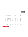
Table 4-2. Default (NVRAM) S-register Settings
S-registers
NVRAM
Default
Setting
S0
Auto Answer
0
S1
Counts & stores rings from incoming calls
0
S2
Escape code character
43
S3
Carriage Return character
13
S4
Line Feed character
10
S5
Backspace character
8
S7
Carrier wait-time, sec
60
S8
Dial pause, sec
2
S9
Carrier Detect time, 100 ms
6
S10
Carrier loss wait-time, 100 ms
7
S11
Tone duration, spacing, ms
70
Working with Memory • Page 4-7
U.S. Robotics I-modem Command Reference
Table 4-2. Default (NVRAM) S-register Settings
S-registers
NVRAM
Default
Setting
S12
Escape code guard time, 500 ms
50
S13
Bit-mapped functions*
0
S14
Bit-mapped functions*
0
S15
Bit-mapped functions*
0
S19
Inactivity/hang up timer
0
S21
Break length, 10 ms
10
S22
XON character
17
S23
XOFF character
19
S24
Pulsed DSR duration, 20 ms
150
S25
DTR recognition time, 10 ms
5
S26
RTS/CTS delay time, 10 ms
1
S27
Bit-mapped functions*
0
S28
V.32 handshake time, 100 ms
8
S29
V.21 handshake time, 100 ms
20
S33
Bit-mapped functions*
0
S34
Bit-mapped functions*
0
Working with Memory • Page 4-8
U.S. Robotics I-modem Command Reference
Table 4-2. Default (NVRAM) S-register Settings
S-registers
NVRAM
Default
Setting
S38
Disconnect wait time, sec
0
S41
Allowable remote log-in attempts
0
S42
Remote Access ASCII character
126
S43
Remote guard time, 500 ms
200
S51
Bit-mapped functions*
0
S53
Bit-mapped functions*
0
S54
Bit-mapped functions*
0
S55
Bit-mapped functions*
0
S56
Bit-mapped functions*
0
S57
Bit-mapped functions*
0
S67
Bit-mapped functions*
0
S68
Bit-mapped functions*
0
* Bit-mapped registers have up to eight functions.
Working with Memory • Page 4-9
U.S. Robotics I-modem Command Reference
Working with Flash Memory
The I-modem permanently stores three conÞguration Òtemplates,Ó or prepared sets of commands, in Flash memory. You can retrieve a template and load it into current memory
using the &Fn command.
&Fn
Load one of the three conÞguration templates from Flash memory into current
memory.
&F0
No ßow control (low performance).
&F1
Hardware ßow control.
&F2
Software ßow control.
All of the settings in each template are given in Table 4-3, 4-4, and Table 4-5. The settings
that change from template to template appear in bold type.
If DIP switch 1 is OFF when you power on or reset the I-modem, or if you load template
&F0, the &F0 settings take effect (see Table 4-5).
Working with Memory • Page 4-10
U.S. Robotics I-modem Command Reference
For more information about hardware and software ßow control, see Chapter 10, Flow
Control.
Table 4-3. &F1 Hardware Flow Control Template
NVRAM Options
Setting
Description
Handshake option
B0
ITU-T answer sequence
Transmitter
C1
Enabled
Command mode echo
E1
Enabled
Online local echo
F1
Disabled
Training tone volume
L2
Medium
Speaker control
M1
ON during dial through connect
Result codes
Q0
Enabled
Verbal or numeric result codes
V1
Verbal result codes
Result code subset
X7
Extended. Includes all
codes except VOICE
Protocol response codes
&A3
Full protocol codes
Serial port rate select
&B1
Serial port rate Þxed higher
than connect rate
Guard tone
&G0
U.S./Canada
Working with Memory • Page 4-11
U.S. Robotics I-modem Command Reference
Table 4-3. &F1 Hardware Flow Control Template
NVRAM Options
Setting
Description
Transmit data hardware ßow control
&H1
Hardware ßow control
Rec'd data software ßow control
&I0
Disabled
Analog data compression
&K1
Enabled
Normal or leased lines
&L0
Normal lines
Error control/sync
&M4
Normal/error control
Link rate select
&N0
Variable
Rec'd data hardware ßow control
&R2
Enabled
Data Set Ready
&S0
Always on
Remote Digital Loopback (RDL)
&T5
Deny RDL
Break handling
&Y1
Clear buffer, send immediately
Stored telephone number
&Z0*9=0
Blank
EXTERNALS ONLY: Synch Clock
Speed
%N6
9600 bps
Call type
*V=0
Auto-detect the call type
Word length*
8
Parity*
0
None
Working with Memory • Page 4-12
U.S. Robotics I-modem Command Reference
Table 4-3. &F1 Hardware Flow Control Template
NVRAM Options
Setting
Description
DTE rate* (Kbps)
19.2
_
* Detected by each I-modem from the AT preÞx of the &W com-mand that writes your defaults
to NVRAM. Set your software to the desired word length, parity, and serial port rate defaults
before sending the modem the AT É&W string.
Table 4-4. &F2 Software Flow Control Template
NVRAM Options
Setting
Description
Handshake option
B0
ITU-T answer sequence
Transmitter
C1
Enabled
Command mode echo
E1
Enabled
Online local echo
F1
Disabled
Training tone volume
L2
Medium
Speaker control
M1
ON during dial through connect
Result codes
Q0
Enabled
Verbal or numeric result codes
V1
Verbal result codes
Working with Memory • Page 4-13
U.S. Robotics I-modem Command Reference
Table 4-4. &F2 Software Flow Control Template
NVRAM Options
Setting
Description
Result code subset
X7
Extended. Includes all
codes except VOICE
Protocol response codes
&A3
Full protocol codes
Serial port rate select
&B1
Serial port rate Þxed higher
than connect rate
Guard tone
&G0
U.S./Canada
Transmit data hardware ßow control
&H2
Software ßow control
Rec'd data software ßow control
&I2
Enabled
Analog data compression
&K1
Enabled
Normal or leased lines
&L0
Normal lines
Error control/sync
&M4
Normal/error control
Link rate select
&N0
Variable
Rec'd data hardware ßow control
&R2
Enabled
Data Set Ready
&S0
Always on
Remote Digital Loopback (RDL)
&T5
Deny RDL
Break handling
&Y1
Clear buffer, send immediately
Working with Memory • Page 4-14
U.S. Robotics I-modem Command Reference
Table 4-4. &F2 Software Flow Control Template
NVRAM Options
Setting
Description
Stored telephone number
&Z0*9=0
Blank
Externals only: V.25bis clock speed
%N6
9600 bps
Call type
*V=0
Auto-detect the call type
Word length*
8
Parity*
0
None
DTE rate* (Kbps)
19.2
_
* Detected by each I-modem from the AT preÞx of the &W com-mand that writes your defaults
to NVRAM. Set your software to the desired word length, parity, and serial port rate defaults
before sending the modem the AT É&W string.
Table 4-5. &F0 No Flow Control Template
NVRAM Options
Setting
Description
Handshake option
B0
ITU-T answer sequence
Transmitter
C1
Enabled
Command mode echo
E1
Enabled
Online local echo
F1
Disabled
Training tone volume
L2
Medium
Working with Memory • Page 4-15
U.S. Robotics I-modem Command Reference
Table 4-5. &F0 No Flow Control Template
NVRAM Options
Setting
Description
Speaker control
M1
ON during dial through connect
Result codes
Q0
Enabled
Verbal or numeric result codes
V1
Verbal result codes
Result code subset
X1
Basic
Protocol response codes
&A3
Full protocol codes
Serial port rate select
&B1
Serial port rate Þxed higher
than connect rate
Guard tone
&G0
U.S./Canada
Transmit data hardware ßow control
&H0
Disabled
Rec'd data software ßow control
&I0
Disabled
Analog data compression
&K1
Enabled
Normal or leased lines
&L0
Normal lines
Error control/sync
&M4
Normal/error control
Link rate select
&N0
Variable
Rec'd data hardware ßow control
&R1
Disabled
Data Set Ready
&S0
Always on
Working with Memory • Page 4-16
U.S. Robotics I-modem Command Reference
Table 4-5. &F0 No Flow Control Template
NVRAM Options
Setting
Description
Remote Digital Loopback (RDL)
&T5
Deny RDL
Break handling
&Y1
Clear buffer, send immediately
Stored telephone number
&Z0*9=0
Blank
Externals only: V.25bis clock speed
%N6
9600 bps
Call type
*V=0
Auto-detect the call type
Word length*
7
Parity*
1
Even
DTE rate* (Kbps)
9600
_
* Detected by each I-modem from the AT preÞx of the &W com-mand that writes your defaults
to NVRAM. Set your software to the desired word length, parity, and serial port rate defaults
before sending the modem the AT É&W string.
Saving ROM Templates to NVRAM
To save one of the four templates in NVRAM and have it serve as the reset default, enter
AT&Fn&W. For example, AT&F1&W <Enter>.
Working with Memory • Page 4-17
U.S. Robotics I-modem Command Reference
Note
DIP switch settings override AT commands at power-on. Make sure DIP
Switch 1 is ON, or the &F0 template will be loaded!
Default Settings
If DIP switch 1 is OFF at power-on, the &F0 settings are loaded instead.
By default, the Þrst time the I-modem is turned on, it loads the settings stored in NVRAM,
which are the same as the settings in the &F1 template.
Until you save any changes to NVRAM, the defaults stored there are the same as the permanent ROM factory settings stored in &F1.
To view the &F1 settings, enter ATI5.
Saving Templates in NVRAM
You can save any of the three templates, or save modiÞed versions of them, in NVRAM
for use as power-on defaults.
Working with Memory • Page 4-18
U.S. Robotics I-modem Command Reference
&W
To substitute a template other than &F1, write the desired template to NVRAM
using the &W command.
AT&F2&W <Enter>
To modify the &Fn conÞguration in NVRAM, type your changes afterward and then save
them to NVRAM, as in the following example (the original factory template remains
intact):
ATS10=40&A2&W <Enter>
Resetting I-modems
Z or Z! Resets and loads the NVRAM settings when DIP switch 1 is ON (factory setting).
If DIP switch 1 is OFF, the I-modem resets and loads the &F0 conÞguration template (no ßow control). Use ATZ or ATZ! to make changes to the DIP switch settings take effect immediately.Table 4-5. &F0 No Flow Control Template
Working with Memory • Page 4-19
U.S. Robotics I-modem Command Reference
Chapter 5
Controlling Result Code Displays
This section explains how to control the display of result codes. ÒResult codeÓ is just
another way of saying Òstatus message.Ó
Result Code Display Commands
The four commands listed below control whether result codes are displayed, and in what
format they are displayed.
Table 5-1. AT Commands That Control Result Code Diplay
Command
Effect
Qn
Enables or suppresses the display of result codes.
Vn
Displays result codes in verbal or numeric form.
Xn
Uses a speciÞed set of result codes.
&An
Uses additional speciÞed sets of result codes.
Controlling Result Code Displays • Page 5-1
U.S. Robotics I-modem Command Reference
Qn
Vn
Xn
Enable/suppress the display of result codes.
Q0
Display result codes.
Q1
Do not display result codes.
Q2
Do not display result codes while in Answer mode (see Chapter 2, Modes
of Operation, for a description of modes).
Display result codes in verbal or numeric form.
V0
Display result codes in numeric form.
V1
Display result codes in verbal form.
Display one of the following sets of result codes. Default = X7 (see Tables 5-2 and
5-3).
Controlling Result Code Displays • Page 5-2
U.S. Robotics I-modem Command Reference
Table 5-2. Result Codes Sets for Xn Values
Setting
Result Codes
X0
X1
X2
X3
X4
X5
X6
0/OK
¥
¥
¥
¥
¥
¥
¥
¥
1/CONNECT
¥
¥
¥
¥
¥
¥
¥
¥
2/RING
¥
¥
¥
¥
¥
¥
¥
¥
3/NO CARRIER
¥
¥
¥
¥
¥
¥
¥
¥
4/ERROR
¥
¥
¥
¥
¥
¥
¥
¥
¥
¥
¥
¥
¥
¥
¥
¥
¥
5/CONNECT 1200
6/NO DIAL TONE
¥
¥
X7
7/BUSY
¥
¥
¥
¥
¥
8/NO ANSWER
¥
¥
¥
¥
¥
¥
¥
¥
¥
¥
11/RINGING
¥
¥
¥
12/VOICE
¥
¥
10/CONNECT 2400
¥
¥
13/CONNECT 9600
¥
¥
¥
¥
¥
¥
¥
18/CONNECT 4800
¥
¥
¥
¥
¥
¥
¥
20/CONNECT 7200
¥
¥
¥
¥
¥
¥
¥
Controlling Result Code Displays • Page 5-3
U.S. Robotics I-modem Command Reference
Table 5-2. Result Codes Sets for Xn Values
Setting
Result Codes
X0
X1
X2
X3
X4
X5
X6
X7
21/CONNECT 12000
¥
¥
¥
¥
¥
¥
¥
25/CONNECT 14400
¥
¥
¥
¥
¥
¥
¥
43/CONNECT 16800
¥
¥
¥
¥
¥
¥
¥
85/CONNECT 19200
¥
¥
¥
¥
¥
¥
¥
91/CONNECT 21600
¥
¥
¥
¥
¥
¥
¥
99/CONNECT 24000
¥
¥
¥
¥
¥
¥
¥
103/CONNECT 26400
¥
¥
¥
¥
¥
¥
¥
107/CONNECT 28800
¥
¥
¥
¥
¥
¥
¥
151/CONNECT 31200
¥
¥
¥
¥
¥
¥
¥
155/CONNECT 33600
¥
¥
¥
¥
¥
¥
¥
162/CONNECT 56000
¥
¥
¥
¥
¥
¥
¥
165/CONNECT 64000
¥
¥
¥
¥
¥
¥
¥
Wait for 2nd Dial Tone (W)
¥
¥
¥
¥
¥
Wait for Answer (@)
¥
¥
¥
¥
¥
Functions
Controlling Result Code Displays • Page 5-4
U.S. Robotics I-modem Command Reference
Table 5-3. Result Code Meanings
Result Code
Meaning
0/OK
Command has been executed.
1/CONNECT
Connection with another device.
2/RING
Incoming ring detected.
3/NO CARRIER
Carrier Detect has failed, or carrier has been dropped due to disconnect.
4/ERROR
Command is invalid.
5/CONNECT 1200
Connection at reported rate. Same meaning for results of 2400 (10),
4800 (18), 7200 (20), 9600 (13), 12000 (21), 14400 (25), 16800 (43),
19200 (85), 21600 (91), 24000 (99), 26400 (103), 28800 (107),
31200 (151), 33600 (155), 56000 (162), or 64000 (165) bps.
6/NO DIAL TONE
Dial tone not detected during the default 2 seconds, set in Register
S6.
7/BUSY
Busy signal detect; I-modem hangs up.
8/NO ANSWER
After waiting 5 seconds for an answer, I-modem hangs up; returned
instead of NO CARRIER when the @ option is used.
11/RINGING
The I-modem has dialed; remote phone line is ringing.
12/VOICE
Voice answer at remote site; I-modem hangs up.
Controlling Result Code Displays • Page 5-5
U.S. Robotics I-modem Command Reference
Table 5-3. Result Code Meanings
Result Code
Meaning
Wait for Another
The I-modem continues dialing as soon as it detects
Dial Tone (W)
another dial tone. See the dial options earlier in this chapter.
Wait for an Answer(@)
The I-modem continues dialing when it detects 5 seconds of silence
on the line. (See the dial options earlier in this chapter.)
Additional Result Code Subsets
Note
ARQ (Automatic Repeat Request) is used in this manual to denote calls
that use error control.
&An
Enable or suppress the display of additional result code subsets.
&A0
Do not display ARQ result codes. This setting pertains only to the display
of codes and not to ARQ function.
&A1
Display ARQ result codes.
Controlling Result Code Displays • Page 5-6
U.S. Robotics I-modem Command Reference
If the I-modem is set to X0 and the connection rate is 1200 bps-64 Kbps, result
code 14 is displayed. The other result codes indicate connection rates and require a
setting of X1 or higher.
ARQ
&A2
14/CONNECT/ARQ
88/CONNECT 19200/ARQ
15/CONNECT 1200/ARQ
94/CONNECT 21600/ARQ
16/CONNECT 2400/ARQ
100/CONNECT 24000/ARQ
17/CONNECT 9600/ARQ
104/CONNECT 26400/ARQ
19/CONNECT 4800/ARQ
108/CONNECT 28800/ARQ
22/CONNECT 12000/ARQ
152/CONNECT 31200/ARQ
24/CONNECT 7200/ARQ
156/CONNECT 33600/ARQ
26/CONNECT 14400/ARQ
168/CONNECT 56000/ARQ
47/CONNECT 16800/ARQ
169/CONNECT 64000/ARQ
Display modulation indicators (HST, V32, VFC, V34, or DIGITAL).
Controlling Result Code Displays • Page 5-7
U.S. Robotics I-modem Command Reference
Note
If your software cannot handle the added modulation information, select
&A1 or &A0.
HST
ARQ/HST
28/CONNECT 4800/HST
29/CONNECT 4800/ARQ/HST
23/CONNECT 9600/HST
27/CONNECT 9600/ARQ/HST
30/CONNECT 7200/HST
34/CONNECT 7200/ARQ/HST
31/CONNECT 12000/HST
32/CONNECT 12000/ARQ/HST
35/CONNECT 14400/HST
36/CONNECT 14400/ARQ/HST
53/CONNECT 16800/HST
57/CONNECT 16800/ARQ/HST
86/CONNECT 19200/HST
89/CONNECT 19200/ARQ/HST
92/CONNECT 21600/HST
95/CONNECT 21600/ARQ/HST
V32
ARQ/V32
38/CONNECT 4800/V32
39/CONNECT 4800/ARQ/V32
33/CONNECT 9600/V32
37/CONNECT 9600/ARQ/V32
40/CONNECT 7200/V32
44/CONNECT 7200/ARQ/V32
41/CONNECT 12000/V32
42/CONNECT 12000/ARQ/V32
45/CONNECT 14400/V32
46/CONNECT 14400/ARQ/V32
83/CONNECT 16800/V32
84/CONNECT 16800/ARQ/V32
Controlling Result Code Displays • Page 5-8
U.S. Robotics I-modem Command Reference
HST
ARQ/HST
87/CONNECT 19200/V32
90/CONNECT 19200/ARQ/V32
93/CONNECT 21600/V32
96/CONNECT 21600/ARQ/V32
VFC
ARQ/VFC
119/CONNECT 2400/VFC
121/CONNECT 2400/ARQ/VFC
123/CONNECT 4800/VFC
125/CONNECT 4800/ARQ/VFC
127/CONNECT 7200/VFC
129/CONNECT 7200/ARQ/VFC
131/CONNECT 9600/VFC
133/CONNECT 9600/ARQ/VFC
135/CONNECT 12000/VFC
137/CONNECT 12000/ARQ/VFC
139/CONNECT 14400/VFC
141/CONNECT 14400/ARQ/VFC
143/CONNECT 16800/VFC
145/CONNECT 16800/ARQ/VFC
147/CONNECT 19200/VFC
149/CONNECT 19200/ARQ/VFC
97/CONNECT 21600/VFC
98/CONNECT 21600/ARQ/VFC
101/CONNECT 24000/VFC
102/CONNECT 24000/ARQ/VFC
105/CONNECT 26400/VFC
106/CONNECT 26400/ARQ/VFC
109/CONNECT 28800/VFC
110/CONNECT 28800/ARQ/VFC
V34
ARQ/V34
120/CONNECT 2400/V34
122/CONNECT 2400/ARQ/V34
Controlling Result Code Displays • Page 5-9
U.S. Robotics I-modem Command Reference
HST
ARQ/HST
124/CONNECT 4800/V34
126/CONNECT 4800/ARQ/V34
128/CONNECT 7200/V34
130/CONNECT 7200/ARQ/V34
132/CONNECT 9600/V34
134/CONNECT 9600/ARQ/V34
136/CONNECT 12000/V34
138/CONNECT 12000/ARQ/V34
140/CONNECT 14400/V34
142/CONNECT 14400/ARQ/V34
144/CONNECT 16800/V34
146/CONNECT 16800/ARQ/V34
148/CONNECT 19200/V34
150/CONNECT 19200/ARQ/V34
111/CONNECT 21600/V34
112/CONNECT 21600/ARQ/V34
113/CONNECT 24000/V34
114/CONNECT 24000/ARQ/V34
115/CONNECT 26400/V34
116/CONNECT 26400/ARQ/V34
117/CONNECT 28800/V34
118/CONNECT 28800/ARQ/V34
153/CONNECT 31200/V34
154/CONNECT 31200/ARQ/V34
157/CONNECT 33600/V34
158/CONNECT 33600/ARQ/V34
DIGITAL
ARQ/DIGITAL
163/CONNECT 56000/DIGITAL
164/CONNECT 56000/ARQ/DIGITAL
166/CONNECT 64000/DIGITAL
167/CONNECT 64000/ARQ/DIGITAL
Controlling Result Code Displays • Page 5-10
U.S. Robotics I-modem Command Reference
&A3
Default. Display error control (LAPM, HST, MNP, SYNC, V120, or
NONE) and data- compression type (V42BIS, MNP5) indicators.
In the following example, the devices negotiated error control for the call
(ARQ), used V.34 modulation, are using the LAPM error-control protocol,
and are using V.42bis compression.
CONNECT 28800/ARQ/V34/LAPM/V42BIS
Note
The numeric identiÞers for &A3 result codes are the same as those used for
&A2. If you request numeric display (V0) and &A3, you wonÕt be able to
distinguish &A2 from &A3 codes. Also, &A3 result codes may not be
compatible with some software.
Controlling Result Code Displays • Page 5-11
U.S. Robotics I-modem Command Reference
Chapter 6
Controlling EIA-232 Signaling
The EIA-2321 interface deals with the signals and voltages used when data is exchanged
between a computer and a serial device, such as a modem or serial printer.
While external I-modems have physical serial ports, internal I-modems have virtual serial
ports. Even though you canÕt see the internal I-modemÕs serial port, the commands
described in this chapter affect its internal serial communications.
Controlling EIA-232 Signaling
Data Terminal Ready
Your computer sends a Data Terminal Ready (DTR) signal to the I-modem when it is
ready to send and receive data (use &Dn to tell the I-modem how to deal with the DTR
signal).
1. The EIA-232 standard was formerly known as RS-232 (RS stands for Recommended Standard).
Controlling EIA-232 Signaling • Page 6-1
U.S. Robotics I-modem Command Reference
&Dn
Tell the I-modem how to deal with the DTR signal.
&D0
Operate as though the DTR signal is always ON.
&D1
Use a change in the DTR signal to enter Command mode. Most communications software packages have a method for toggling DTRÑrefer to your
softwareÕs manual for details.
&D1 functions similarly to the escape code (+++). Return online with the
On command, or hang up with the ATH command.
&D2
Respond normally to the DTR signal. The I-modem will not accept commands until your computer sends a DTR signal. The call will end when the
DTR signal is dropped.
To change the DTR recognition time, set S-register 25. (See Appendix A,
Alphabetic Command Summary.)
Data Set Ready
Data Set is another name for the I-modem. Under normal conditions, the I-modem sends a
Data Set Ready (DSR) signal to your computer when it is ready to send and receive data.
Controlling EIA-232 Signaling • Page 6-2
U.S. Robotics I-modem Command Reference
Do not change the default setting of &S0 unless you know that your installation requires a
different setting. Few communications programs, if any, will require the I-modem to control DSR (&S1).
&Sn
Control how the I-modem sends the DSR signal.
&S0
Send the DSR signal at all times. Default.
&S1
When originating a call, send the DSR signal after dialing when the
I-modem detects the remote analog deviceÕs answer tone. When answering
a call, send DSR after the I-modem sends its answer tone.
&S2
Use this option for specialized equipment such as automatic callback units.
After sending Carrier Detect (CD), send a pulsed DSR signal, followed by
a Clear to Send (CTS) signal.
&S3
Same as &S2, but do not send the CTS signal.
&S4
Send a DSR signal to your computer at the same time the I-modem sends
the CD signal.
&S5
Send DSR normally (with CTS) after sending CD.
Controlling EIA-232 Signaling • Page 6-3
U.S. Robotics I-modem Command Reference
To change the DSR pulse time (in 20-second increments), set S-register 24.
(See Appendix A, Alphabetic Command Summary.)
Carrier Detect
Carrier is another way of saying Òready signal from the device on the other end of the connection.Ó Under normal conditions, the I-modem sends a Carrier Detect (CD) signal in
response to receiving the carrier from the device on the other end.
&Cn
Control how the I-modem sends the CD signal.
&C0
CD always ON.
&C1
Send CD normally: The I-modem sends a CD signal when it connects with
another analog device, and drops the CD signal when it disconnects.
Controlling EIA-232 Signaling • Page 6-4
U.S. Robotics I-modem Command Reference
Chapter 7
Controlling Data Rates
You can set the I-modem to use Þxed or variable serial port rates and Þxed or variable
connection rates. Serial port rates pertain to data transferred between your computer and
the I-modem. Connection rates pertain to data transferred between the I-modem and the
device at the other end of a connection.
Serial Port Rates
Set a Þxed serial port rate to get the highest possible throughput and the best performance.
Set a variable rate to allow the I-modem to match the connection rate.
Your software must support Þxed or variable serial port rates, and must be set to one of the
two settings.
Note
Your software may use terms such as locked serial port (Þxed rate) or autobaud (variable rate).
Controlling Data Rates • Page 7-1
U.S. Robotics I-modem Command Reference
&Bn
Set the serial port rate as variable or Þxed.
&B0
Variable rates. Allows the I-modem to change its serial port rate to match
the connection rate.
&B1
Fixed rate. The I-modem always communicates with an attached device at
the rate at which you have set the terminal or software, regardless of the
connection rate.
For the greatest throughput, set the serial port to 115200, 57600, or 38400
bps for high-speed calls, and to at least 9600 bps for 2400-bps calls.
Note
The serial port rate must be equal to or higher than the &Nn rate.
&B2 Set the serial port rate as Þxed for ARQ calls and variable for non-ARQ
calls (see Chapter 11, Handshaking, Data Compression, and Error Control,
for more information about ARQ) when answering only. When the
I-modem connects in ARQ mode, it shifts its serial port rate to a rate that
you specify using your communications software (for example, 38.4
Kbps). If the connection is not under error control, I-modems behave as if
they were set to &B0 and switch their serial port rates to match the connection rate of each call.
Controlling Data Rates • Page 7-2
U.S. Robotics I-modem Command Reference
To implement this feature, Þrst set your software to the desired rate. Then
send the AT&B2&W command.
I-modems store the rate of the command in NVRAM along with the settings. The I-modem checks NVRAM for the speciÞed serial port rate each
time it makes an ARQ connection.
When sending subsequent conÞgurations to NVRAM, be sure your software is set to your selected serial port rate so the correct rate is maintained.
Connection Rates
The I-modem can be set to a Þxed or variable connection rate for analog calls. Set a variable rate to have each I-modem negotiate with the remote device for the highest possible
connection rate. Set a Þxed rate to connect only at a speciÞed rate. You might use a Þxed
rate to Þlter calls for security or other reasons.
Note
The connection rate must always be lower than or equal to the serial port
rate.
&Nn
Connection rate for analog calls: variable or Þxed.
Controlling Data Rates • Page 7-3
U.S. Robotics I-modem Command Reference
&N0 Variable rates. Negotiate for the highest possible rate.
&N1-&N16 Fixed rate. Connect only if the remote device is operating at the rate
you specify.
&N1
300 bps
&N9
16.8 Kbps
&N2
1200 bps
&N10
19.2 Kbps
&N3
2400 bps
&N11
21.6 Kbps
&N4
4800 bps
&N12
24.0 Kbps
&N5
7200 bps
&N13
26.4 Kbps
&N6
9600 bps
&N14
28.8 Kbps
&N7
12.0 Kbps
&N15
31.2 Kbps
&N8
14.4 Kbps
&N16
33.6 Kbps
Controlling Data Rates • Page 7-4
U.S. Robotics I-modem Command Reference
Chapter 8
Remote Access
You can set up the I-modem so other devices can view or change its conÞguration
remotely.
This feature might be helpful if you have problems connecting with another device: you
could grant the other deviceÕs administrator access to your I-modem to check or correct its
conÞguration.
As the administrator of a multiport I-modem, you might use remote access if you are away
from your multiport I-modem and want to make changes to its conÞguration.
Please review these terms before you continue:
Local
The device that is directly connected to the computer you are using.
Remote
The device at the other end of a telephone connection.
Host
The I-modem that will be accessed and controlled by other devices.
Guest
The device that will access and control the host I-modem.
Remote Access • Page 8-1
U.S. Robotics I-modem Command Reference
Setting Up Remote Access
At the Host I-modem
1. Prepare to send AT commands.
See Chapter 1, Using the AT Command Set, for details.
2. Enable remote access.
Set Register S41 for a value of 1 or greater. S41 sets the number of log-in attempts
available to the remote user. A setting of zero allows no log-in attempts, disabling
remote access.
ATS41=1&W <Enter>
Note
This method will not work if the multiport I-modem is attached to certain
synchronous devices. Refer to your Getting Started manual.
3. Set one or two remote-access passwords.
You can set two passwords to allow different levels of access to each I-modem:
Remote Access • Page 8-2
U.S. Robotics I-modem Command Reference
View-Only
Only allows guest users to view the I-modemÕs conÞguration.
View-and-Change
Allows guest users to view and change the I-modemÕs conÞguration.
Remote-access passwords can be up to eight alphanumeric characters long, and are not
case-sensitive.
%Pn
Assign a remote-access password.
%P0
Assign a view-only password.
AT%P0=password <Enter>
%P1
Assign a view-and-change password.
AT%P1=password <Enter>
Other Remote-Access Commands
Displaying a Remote-Access Password
To display a remote-access password, type:
AT%P0? <Enter> or AT%P1? <Enter>
Remote Access • Page 8-3
U.S. Robotics I-modem Command Reference
Erasing a Remote-Access Password
To erase a remote-access password, type:
AT%P0= <Enter> or AT%P1= <Enter>
Warning Keep in mind that if you erase the %P1 password without disabling
remote access (using ATS41=0), anyone could access the I-modem and
change its conÞguration.
Disabling Remote Access
To disable remote access entirely, set S-Register 41 to 0:
ATS41=0 <Enter>
Accessing the Host
At the Guest Device
The guest device requires no conÞguration to access the host. The guest device does not
need to be made by U.S. Robotics. Follow these steps:
Remote Access • Page 8-4
U.S. Robotics I-modem Command Reference
1. Be sure that the host device has enabled remote access and is set to auto-answer
(ATS0=1). Know the password, if you will need one.
2. Call the host device (although it doesnÕt matter which device originates the call).
3. After a connection is established, do this:
a. Pause 4 seconds.
b. Type 4 tildes: ~~~~
c. Pause 4 seconds.
Note
The administrator of the host device can change the remote-access character using S-Register 42, and the pause duration using S-Register 43.
4. You should see a display similar to this:
U.S. Robotics Courier I-modem with ISDN/V.34 Remote Access Session
Serial Number 000000A000000001
Password (Ctrl-C to cancel)?
There is a 3-minute time limit for entering the password.
If the number of unsuccessful log-in attempts exceeds the set limit, the host device
returns online and refuses any further log-in attempts during the remainder of the con-
Remote Access • Page 8-5
U.S. Robotics I-modem Command Reference
nection.
When the host accepts the password, the following message and prompt will appear on
your screen:
Remote Access granted
Remote->
Note
You may not be prompted for a password. If you arenÕt, password security
is not active. The following prompt appears on your screen after you type
the four tildes: Remote Access granted (query only), and then Remote->.
5. Continue with Viewing and Changing the HostÕs ConÞguration, later in this chapter.
Keep in mind that there is a 3-minute inactivity timer. If the host device detects no
activity for 3 minutes, it quits the remote-access session and resumes a normal online
connection.
Also, during a remote-access session, the maximum number of characters between carriage returns is 40.
Remote Access • Page 8-6
U.S. Robotics I-modem Command Reference
Quitting a Remote-Access Session
If you want to quit the remote-access login before you have entered the password, return
online by pressing <Ctrl>C or typing ATO<Enter>. After youÕve entered the password,
you can quit by sending one of these commands:
¥ ATO ends the remote-access session and keeps the connection.
¥ ATH ends the remote-access session and ends the connection.
¥ ATZ ends the remote-access session, ends the connection, and resets the guest modem.
Viewing and Changing the HostÕs ConÞguration
Once you've gained guest access to a host, you can communicate with the host just as if
you were entering commands from its attached computer.
Depending on your access privileges, you can use the regular set of I-modem AT commands (see Table 8-1).
Remote Access • Page 8-7
U.S. Robotics I-modem Command Reference
Table 8-1. Access Privileges
Note
Access Privileges
What You Can Do
View-Only
Use any of the inquiry (ATI) commands.
View and ConÞgure
Use any of the I-modem commands, except those that cannot
be used while online (for example, ATD or ATA). You can also
use remote conÞguration commands.
Be careful not to send ATZ or ATZ! or you will lose the connection!
Remote ConÞguration Commands
There are special commands that can be used only during a remote-access session:
%Bn
%Bn
Change the host I-modemÕs serial port rate.
%Fn
Change data format (parity and data bits).
%Cn
Control whether and when to apply changes to the conÞguration.
Change the host I-modemÕs serial port rate.
%B0
110 bps
%B6
9600 bps
%B1
300 bps
%B7
19200 bps
Remote Access • Page 8-8
U.S. Robotics I-modem Command Reference
%B2
600 bps
%B8
38400 bps
%B3
1200 bps
%B9
57600 bps
%B4
2400 bps
%B10
115200 bps
%B5
4800 bps
%Fn Change data format.
%Cn
%F0
No parity, 8 data bits.
%F1
Mark parity, 7 data bits.
%F2
Odd parity, 7 data bits.
%F3
Even parity, 7 data bits.
Control whether and when to apply changes to the conÞguration.
%C0
Defer changes. Default. Any changes you make to the conÞguration are
deferred until the call is ended; they take effect for ensuing connections.
Remote Access • Page 8-9
U.S. Robotics I-modem Command Reference
Note
Even though, by default (%C0), the changes you make do not take effect
until the next connection, the new conÞgu-ration is reßected immediately
in inquiry responses (ATIn).
%C1
Note
Restore the original conÞguration. Use this command to cancel any
changes made during remote access and restore the original conÞguration.
Commands that have been written to NVRAM (using &W) and forced conÞguration changes (using %C2) will not be restored to their previous settings when you send the host %C1.
%C2
Force conÞguration changes. Use this command to make conÞguration
changes take effect immediately. We do not recommend forcing changes
unless it is absolutely necessary because an unreliable connection, or even
a loss of connection, may result.
After you make changes to the hostÕs conÞguration, the remote- access prompt changes
from Remote-> to Remote+>.
If you restore the original conÞguration using %C1, the top prompt is restored, assuring
you the original conÞguration is intact.
Remote Access • Page 8-10
U.S. Robotics I-modem Command Reference
Quitting a Remote-Access Session
If you want to quit the remote-access login before you have entered the password, return
online by pressing <Ctrl>C or typing ATO<Enter>. After youÕve entered the password,
you can quit by sending one of these commands:
¥ ATO ends the remote-access session and keeps the connection.
¥ ATH ends the remote-access session and ends the connection.
¥ ATZ ends the remote-access session, ends the connection, and resets the guest device.
Remote Access • Page 8-11
U.S. Robotics I-modem Command Reference
Chapter 9
Dial Security
Dial Security is designed to protect networks and data centers from unauthorized access.
A few terms need to be explained before we go any further:
Local
The device that is directly connected to the computer you are using.
Remote
The device at the other end of a telephone connection.
Host
The I-modem that receives calls from other devices and provides Dial
Security.
Guest
The device that accesses the host.
You can conÞgure up to 10 accounts: one administrative account for you and nine
accounts for guest users. The account proÞles are stored in the host I-modemÕs nonvolatile
random access memory (NVRAM).
There are two forms of Dial Security; each will be explained later in this chapter:
Dial Security • Page 9-1
U.S. Robotics I-modem Command Reference
¥ Autopass
¥ Password Prompting
Setting Up Dial Security
Here is a summary of the steps for setting up Dial Security:
¥ Set up an account for yourself.
¥ Identify your account as the Administrative Account.
¥ Set up guest-user accounts.
¥ Enable local (host) security.
¥ Choose a Dial Security method.
¥ Enable Dial Security.
¥ Activate the Dial Security settings.
Dial Security • Page 9-2
U.S. Robotics I-modem Command Reference
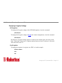
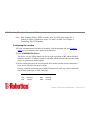
1. Set up an account for yourself.
Use any of the 10 available accounts (numbered 0Ð9) for your account.
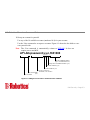
Use the %An command to set up user accounts. Figure 9-1 shows the Þve Þelds to concern yourself with.
Note
The %An command is automatically written to NVRAM. It does not
require you to send &W.
AT%A0=password,y,y,n,5551000
SpeciÞed dialback number
(up to 37 ASCII characters)
Prompt user for dialback number? (y/n)
Dialback enabled? (y/n)
Account enabled? (y/n)
Password. 8 characters
maximum, case sensitive
Account number
(0-9)
%A command
Figure 9-1. Adding Accounts: How to Format the %An command
Dial Security • Page 9-3
U.S. Robotics I-modem Command Reference
Dialback at a SpeciÞed Number
To make the host I-modem hang up and then dial back a guest device at a speciÞed number, type:
AT%A0=nanook,y,y,n,17085555555 <Enter>
To enable Dialback, you must enable Dial Security with Prompting in step 6.
Dialback at a New Number
To make the host I-modem prompt you to enter a number at which to dialback a device,
and then have the I-modem dialback at device at that number, type:
AT%A0=nanook,y,y,y, <Enter>
To enable Dialback, you must enable Dial Security with Prompting in step 6.
No Dialback
To disable dialback, type, for example:
AT%A0=nanook,y,n,, <Enter>
Note
Count your commas! There should always be four commas in the %A command.
Dial Security • Page 9-4
U.S. Robotics I-modem Command Reference
Warning Do not insert spaces between commas or between Þelds and commas.
Spaces will invalidate the command.
2. Identify your account as the Administrative Account.
Identify your account as the Administrative Account using the %L command.
AT%L=PW0 <Enter>
This example sets account 0 as the Administrative Account.
Once you set the administrative password, you cannot view or modify the guest account
proÞles unless you enter the correct administrative password.
Warning Be sure to remember your administrative password. If you enable Dial
Security and then forget your administrative password, you will be
locked out of the I-modem.
Dial Security • Page 9-5
U.S. Robotics I-modem Command Reference
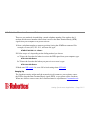
3. Set up guest-user accounts.
Use the %An command to set up guest-user accounts in the same way you set up your
administrative account. You can set up nine guest accounts (see Figure 9-2).
AT%A0=password,y,y,n,5551000
SpeciÞed dialback number
(up to 37 ASCII characters)
Prompt user for dialback number? (y/n)
Dialback enabled? (y/n)
Account enabled? (y/n)
Password. 8 characters
maximum, case sensitive
Account number
(0-9)
%A command
Figure 9-2. Adding Accounts: How to Format the A%n command
After you have enabled the guest accounts, make sure the guest users know their passwords and the log-in procedure.
Dial Security • Page 9-6
U.S. Robotics I-modem Command Reference
Modifying Accounts
After you have set up an account, you can modify each Þeld independently. If a Þeld is to
remain as is, just insert a comma, as shown in the following command:
AT%A1=,,,Y, <Enter>
The command above allows the guest user to supply a dialback number that is different
from the one stored in the original account record.
4. Enable Local Security.
If you do not enable Local Security, the Dial Security settings will not be protected and
other users will be able to change or erase them. Once the administrative password is
protected, when security commands are issued, the I-modem will reply [ ACCESS
DENIED ].
ATS53.2=1&W <Enter>
5. Decide which Dial Security option to use.
You can choose from two types of Dial Security: Autopass and Password Prompting.
Dial Security • Page 9-7
U.S. Robotics I-modem Command Reference
Autopass
Autopass is the default form of password protection. Autopass automates the process of
logging in to the host modem, but it requires close cooperation between the guest and host
devices.
Using Autopass requires that:
¥ Both the host and guest devices are made by U.S. Robotics and have Dial Security
enabled.
¥ The connection between the I-modems or modems is under V.42 error control (that is,
both modems must be set to &M4 or &M5).
Note
Since V.42 error control is not available for V.120 and V.110 connections,
Autopass is not available for calls that use those protocols.
When a guest device attempts an Autopass connection, the guest includes its password in
its V.42 error-control request. The host modem checks all the enabled passwords in its
security accounts for a match.
¥ If the guest includes an invalid password, the host sends an INVALID PASSWORD
message and hangs up.
Dial Security • Page 9-8
U.S. Robotics I-modem Command Reference
¥ If the guest did not enable Dial Security, the host will not accept the call unless
prompting is enabled on the host I-modem.
¥ If the guest includes a valid password, the host permits a secure connection.
Password Prompting
While the use of Autopass is restricted to U.S. Robotics devices with Dial Security, Password Prompting allows connections with any guest device, as long as the guest user knows
the correct password.
When host has Password Prompting enabled, it asks guest users for a password. The host
modem checks the received password against each of its active Security accounts.
¥ The host will always respond to a correct Autopass attempt, even if Password Prompting
is enabled.
¥ If the guest sends an invalid password, the host prompts twice more before disconnecting.
¥ If the guest does not send a password after 60 seconds, the host disconnects.
¥ If the guest sends a valid password within 60 seconds, the host permits a secure connection.
Dial Security • Page 9-9
U.S. Robotics I-modem Command Reference
Note
There is no Password Prompting capability in analog synchronous mode.
Password Prompting is more ßexible than Autopass because:
¥ Password Prompting doesn't require guest devices to support U.S. Robotics Dial Security.
¥ Password Prompting doesn't require a V.42 error-control connection.
6. Enable Dial Security.
Warning Before you enable Dial Security, you must set up an administrative
account and password. See Steps 1 & 2.
To enable Autopass Dial Security, type:
AT S53.0=1&W <Enter>
To enable Dial Security with Password Prompting (this also enables Autopass), type:
AT S53.0=1.1=1&W <Enter>
To enable Dialback Security, enable Password Prompting and enable Dialback in
each guest account (see step 3).
Dial Security • Page 9-10
U.S. Robotics I-modem Command Reference
Note
You must use the &W command to save the settings in NVRAM. If you
donÕt, the next time you reset or power off the I-modem, Dial Security will
be disabled.
ati10
USRobotics Courier I-modem with ISDN/V.34
DIAL SECURITY STATUS
DIAL SECURITY ENABLED:[N]S53.0=1
LOCAL SECURITY ENABLED:[N]S53.2=1
PROMPTING ENABLED:[N]S53.1=1
FORCED AUTOPASS:[N]S53.0=1
LOCAL ACCESS PASSWORD:[NO PSW]%L=PWn
AUTOPASS PASSWORD:[NO PSW]%V=PWn
ACCOUNT PSW
%A
%A
#0
#1
#2
#3
#4
#5
#6
#7
#8
#9
PHONE #
%A
ACCT/E DIAL/B NEW_#
%A
%A
%A
[N]
[N]
[N]
[N]
[N]
[N]
[N]
[N]
[N]
[N]
[N]
[N]
[N]
[N]
[N]
[N]
[N]
[N]
[N]
[N]
[N]
[N]
[N]
[N]
[N]
[N]
[N]
[N]
[N]
[N]
Dial Security • Page 9-11
U.S. Robotics I-modem Command Reference
OK
Figure 9-1. The ATI10 Screen. Bold Characters Indicate the Commands Used
to Control the Adjacent Fields
7. Send ATZ or ATZ! to activate the Dial Security settings!
Note
Make sure that DIP switch 1 is ON, which tells the I-modem to load the
settings stored in NVRAM. If DIP switch 1 is OFF, the settings in ROM
(&F0) are loaded, disabling Dial Security. You can retrieve the Dial Security settings by setting DIP switch 1 ON and then resetting the I-modem
using ATZ or ATZ! or by powering off the I-modem and powering it back
on.
Maintaining Security Accounts
Once the administrative password is set and Dial Security is enabled, the administrator is
the only one who can access account information.
To modify or change account information, use the %S= and %E= commands described on
the next page.
Dial Security • Page 9-12
U.S. Robotics I-modem Command Reference
Accessing Account Information (%S)
Once Dial Security is enabled, you can access accounts by entering the local access password using the %S= command, which allows access to the accounts by disabling local
security.
AT%S=administrative password <Enter>
Note
The device echoes the administrative password, which is case-sensitive.
I-modems will accept an invalid password entry, but will lock out users
from the security commands.
For example, if the password is Green, but you enter GREEN, an OK is displayed. However, if you try to type a security command (for example, ATI10 <Enter> to view
accounts), an [ ACCESS DENIED ] message is displayed.
Account Status
Once access has been granted, you can view account information by typing:
ATI10 <Enter>
Remote users may only use this command during a remote-access session if local-access
security is disabled.
Dial Security • Page 9-13
U.S. Robotics I-modem Command Reference
Erasing Account Information (%E)
Use the %E=n command to make system edits.
%E=1
Erase local-access password.
%E=2
Erase Autopass password.
%E=3
Erase passwords in accounts 0Ð9.
%E=4
Erase phone numbers in accounts 0*9.
%E=5
Disable Account, Dialback, and New Number Þelds in accounts 0*9.
To edit or overwrite an individual account or an individual account Þeld, use the %An=
command described in Setting Up Dial Security earlier in this chapter.
Remote ConÞguration
Dial Security accounts may be conÞgured remotely. (See ConÞguring Dial Security
Remotely at the end of this chapter.)
Dial Security • Page 9-14
U.S. Robotics I-modem Command Reference
What the Guest User Needs to Do
When guest users want to call in to the host (assuming you have enabled Dial Security by
entering ATS53.0=1),
¥ They must know the password.
¥ If you have enabled Dialback, they must set their device to auto-answer.
1. If the host has security enabled, get a password from the hostÕs administrator. The password is case-sensitive, so be sure to copy it correctly.
If the host has prompting enabled and the host operator enables Dialback for your
account, skip to Step 3.
2. For guest users with COURIER modems only:
a. Create a security account using the password the hostÕs administrator asked you to
use. (See Setting Up Dial Security, earlier in this chapter, for instructions.)
b. Using the %V command, assign the password as your Autopass password. Enter the
following command, where n is the number of the account you set up:
AT%V=PWn <Enter>
Dial Security • Page 9-15
U.S. Robotics I-modem Command Reference
c. Check to see that you've set your Autopass password correctly by typing the following command:
ATI10 <Enter>
Your Autopass password appears beside AUTOPASS PASSWORD.
d. Once the Autopass password is set, enable your CourierÕs Dial Security by sending
the following command:
ATS53.0=1&W <Enter>
3. If Dialback is enabled at the host I-modemÕs site, set your modem to answer the host
I-modem when it dials back.
To set your modem to answer the Dialback call, send the following command:
AT S0=1 <Enter>
4. Call the host.
5. To disable Auto Answer, type the following command after the call ends:
AT S0=0 <Enter>
Dial Security • Page 9-16
U.S. Robotics I-modem Command Reference
ConÞguring Dial Security Remotely
The host administrator can conÞgure the hostÕs security settings remotely.
Note
At the host device, you must have previously enabled remote access and
assigned a remote-access password that allows view-and-change privileges
(see Chapter 8, Remote Access). You may want to use your administrative
password as your remote-access password.
Dialing In From the Remote Site
1. From the remote site, connect to the host using Dial Security. Once a connection is
made, follow the instructions for beginning a remote-access session as described in
Chapter 8, Remote Access.
2. When remote access has been granted, use the %S= command to access the Dial Security accounts.
You can view the security account information by typing:
ATI10 <Enter>
3. Make any conÞguration changes and execute them immediately by typing:
AT%C2 <Enter>
Dial Security • Page 9-17
U.S. Robotics I-modem Command Reference
4. To end the remote session and reactivate Dial Security on the host, reset the guest
device by typing:
ATZ <Enter>
Warning If you do not use the ATZ command to end a remote-access session,
Dial Security will remain disabled at the host, and anyone dialing in to
the host for remote access will have access to the I10 screen and all
Dial Security accounts.
Dial Security • Page 9-18
U.S. Robotics I-modem Command Reference
Chapter 10
Flow Control
The I-modem has two buffers, one for data transmitted from your computer, and one for
data received from the phone line. Buffers are data-storage areas of variable size.
Flow control provides a system for stopping and starting transmission depending on how
full the buffers are. Its goal is to prevent overÞlling the buffers and losing data.
There are two kinds of ßow control: hardware and software. I-modems support both, but
your computer and communications software must also support the kind of ßow control
you choose.
Note
We recommend that you use hardware ßow control. If you do, depending
on your communications software, you may also need to disable your communications softwareÕs software ßow control.
Flow Control • Page 10-1
U.S. Robotics I-modem Command Reference
Hardware and Software Flow Control
Hardware Flow Control
I-modems implement hardware ßow control by detecting that a buffer is 90% full and then
interrupting the Clear to Send (CTS) signal to stop the ßow of data. When the buffer is
50% full, the I-modem sends CTS to restart the ßow of data.
Software Flow Control
I-modems implement software ßow control by detecting that a buffer is 90% full and then
sending special characters in the data stream to stop the ßow of data. When the buffer is
50% full, the I-modem sends special characters in the data stream to restart the ßow of
data.
The problem with software ßow control is that the characters used to stop (<Ctrl>Q) and
start (<Ctrl>S) the ßow of data can occur naturally in the data ßow. Enabling software
ßow control instructs the I-modem to recognize and act on these characters, even if they
are not intended to control the data ßow.
Using software ßow control may prove satisfactory if you're transferring text Þles only.
Flow Control • Page 10-2
U.S. Robotics I-modem Command Reference
If you use software ßow control and are transferring non-text (binary) Þles or using an
XMODEM-type protocol, disable ßow control entirely using the &R1 and &I0 commands
described in this section. In addition, set the serial port and connection rates equal using
the &B0 and &N0 commands described in Chapter 7, Controlling Data Rates.
The start command is called XON (for transmit on) and the stop command is called XOFF
(transmit off). You can change the characters used. See Registers S22 and S23 in Appendix
A, Alphabetic Command Summary. Appendix B includes an ASCII chart, which you may
Þnd helpful when setting the S-Registers.
Received and Transmit Data Flow Control
Received-Data Flow Control
The default ßow control settings are &R2 &I0, which turns hardware ßow control on and
software ßow control off for received data.
&Rn
Alter hardware ßow control for received data.
Flow Control • Page 10-3
U.S. Robotics I-modem Command Reference
&In
&R0
After sending the Request to Send (RTS) signal, pause before sending
CTS. The delay is required by some synchronous mainframes and does not
apply to asynchronous calls.
&R1
Ignore the RTS signal. &R1 is required if your computer or software does
not support RTS.
&R2
Default. Hardware ßow control enabled. The I-modem sends data to your
computer only upon receipt of the RTS signal.
Alter software ßow control for received data.
&I0
Disable software (XON/XOFF) ßow control. Recommended for non-ARQ
(Normal mode) calls, but see &I5.
While the I-modem is online, the only characters it recognizes are +++, the
escape code.
&I1
Enable software (XON/XOFF) ßow control. Use in ARQ mode only.
Flow Control • Page 10-4
U.S. Robotics I-modem Command Reference
Keep in mind that the XON/XOFF characters sent to the remote computer
may interfere with XON/XOFF signaling between the remote computer
and remote device. See &I2.
&I2
The I-modem acts on your XON/XOFF commands, but removes them from
the data stream instead of passing them to the remote computer.
This ensures that the remote computer does not confuse your XON/XOFF
characters with those from its attached device. This is the recommended
setting for ARQ mode.
Note
If the call is not in ARQ mode, there is no ßow control on the link. If you
send an XOFF to your modem and it stops passing data, it has no way to
tell the remote computer and modem to stop sending for a while, and the
I-modemÕs buffer may overßow. For more reliable control in non ARQ
mode, see &I5.
&I3
Hewlett PackardÐHost mode. Applies only to I-modems attached to an HP
mainframe that uses the ENQ/ACK proto-col. Use in ARQ mode only.
Flow Control • Page 10-5
U.S. Robotics I-modem Command Reference
&I4
Hewlett PackardÐTerminal mode. Applies only to I-modems attached to
terminals in an HP system that uses the ENQ/ACK protocol. Use in ARQ
mode only.
&I5
Enable ßow control when the connection is not under error control. For this
to work, the remote device must also have &I5 capability.
In ARQ mode, an I-modem set to &I5 operates the same as it does when set
to &I2. It acts on your XON/XOFF commands, but does not pass them to
the remote system. The error-control protocol enables the devices to control the ßow of data on the phone link.
In non-ARQ mode, an I-modem set to &I5 operates as though ßow control
were disabled (&I0); it does not look for your typed XON/XOFF commands. However, it does look for XON/XOFF characters coming in over
the phone link. When the remote device sends XON/XOFF com-mands, the
I-modem either resumes or stops transmitting data over the link and drops
the characters from the data stream.
If both devices are set to &I5, operators at each end can signal the remote
device to stop sending, thereby controlling the data ßow on the phone link
Flow Control • Page 10-6
U.S. Robotics I-modem Command Reference
and preventing their own deviceÕs buffer from overßowing. At the computer/device interfaces, the devices independently control the ßow of data
through their Transmit Data (&H) settings.
Transmit-Data Flow Control
This type of ßow control is for data transmitted to the I-modem by its attached computer.
Non-ARQ connections allow the use of error control Þle transfer protocols, such as
XMODEM and YMODEM without ßow control.
&Hn
Alter the transmit-data ßow control.
&H0
Disable transmit data ßow control.
&H1 Hardware ßow control. Requires that your computer and software support
Clear to Send (CTS) at the EIA-232 interface.
&H2
Software ßow control. Requires that your software support XON/XOFF
signaling.
Flow Control • Page 10-7
U.S. Robotics I-modem Command Reference
&H3
Use both hardware and software ßow control. If you are unsure about what
your equipment supports, select this option.
Flow Control • Page 10-8
U.S. Robotics I-modem Command Reference
Chapter 11
Handshaking, Error Control,
Data Compression, and Throughput
Handshaking
With each call, the I-modem goes through a link negotiation process with the remote
device. Another name for the negotiation process is Òhandshaking.Ó
The way in which the I-modem handles outgoing and incoming calls depends on the call
type setting youÕve chosen. You can set the I-modem to handle calls one of six different
ways: Universal Connect, Internet access, clear-channel synchronous, V.120 only, V.110
only, or analog modem/fax emulation.
Handshaking, Error Control, Data Compression, and Throughput • Page 11-1
U.S. Robotics I-modem Command Reference
Universal Connect
When you set the I-modem to Universal Connect and make or receive a call, the I-modem
tries a number of calls and detection processes.
Call
Call Type
Protocol
1
64 Kbps Digital
V.120
2
56 Kbps Digital
V.120
3*
£19.2 Kbps Digital
V.110
4
3.1 kHz Audio
V.34/V.FC/V.32terbo/etc.
*A Note About V.110 Connections
V.110 connections are not attempted by default. The I-modem attempts a V.110 connection
only if you set S67.0=1. When V.110 is enabled, the I-modem makes the V.110 attempt
third in the Universal Connect sequence.
In-Band Monitoring
Because the possibility always exists that calls can be labeled incorrectly by the telephone
companyÕs equipment, the I-modem monitors and compares the call set-up messages and
the activity on the line.
Handshaking, Error Control, Data Compression, and Throughput • Page 11-2
U.S. Robotics I-modem Command Reference
By default, In-band Monitoring is active during every connection attempt the I-modem
makes. You can, however, disable parts of the monitoring process.
Monitor
If detected, the
I-modemÉ
To disable
If disabled and then
detected, I-modemÉ
64 Kbps V.120
Connects at 64 Kbps
V.120
S67.1=1.2=0
Ends connection attempt
56 Kbps V.120
Connects at 56 Kbps
V.120
S67.1=1.2=1
Ends connection attempt
Voice
Tries call again at 3.1 kHz S68.1=1
Audio instead of digital
Ends connection attempt
Modem/fax
Connects modem/fax
call over digital connection
Ends connection attempt
S68.0=1
TurboPPP
TurboPPP mode permits both Internet and remote LAN access. It allows you to use any
networking software that is capable of delivering asynchronous Point-to-Point Protocol
(PPP) through your computerÕs serial port. (NetManage Chameleon and Trumpet Winsock
are examples.)
Handshaking, Error Control, Data Compression, and Throughput • Page 11-3
U.S. Robotics I-modem Command Reference
By default, the I-modem tries to establish a multilink PPP (MP-PPP) session. You can set
up the I-modem to skip either the 64 Kbps or the 56 Kbps call. To skip the 64 Kbps call,
set S67.1=1.2=0. To skip the 56 Kbps call, set S67.1=1.2=1.
You can change whether the I-modem makes one or two calls by a combination of bit 3, Sregister 68 and the use of an ampersand (&) in the dial string, as shown in Table 11-1.
Number of calls made
Dial string
S68.3=0
S68.3=1
ATDT5550001
2
1
ATDT5550001&
2
2
ATDT5550001&5550002
2
2
You can disable TurboPPP by turning on bit 2 of S-Register 68 (send ATS68.2=1
<Enter>). When TurboPPP is disabled, the I-modem performs asynchronous PPP to synchronous PPP conversion, but uses only one B-channel with no compression.
Clear-Channel Synchronous (External I-modems Only)
The I-modem sets up a clear channel (64 or 56 Kbps) with a remote device. Common
applications are videoconferencing and remote access to mini- or mainframe computers.
For more details, see Chapter 16, Analog Synchronous Applications.
Handshaking, Error Control, Data Compression, and Throughput • Page 11-4
U.S. Robotics I-modem Command Reference
V.120 Rate Adaptation
If you set the I-modem to V.120, it will negotiate only for V.120 connections. If a V.120
connection cannot be made, the I-modem does not negotiate for other types of connections.
V.110 Rate Adaptation
If you set the I-modem to V.110, it will negotiate only for V.110 connections. If a V.110
connection cannot be made, the I-modem does not negotiate for other types of connections.
Analog Modem or Fax Emulation
The I-modem does not try to make a digital connection and works only in Analog mode. If
you know youÕll make and receive only analog calls, this setting shortens the connect time.
Analog Mode Handshaking
When making analog connections, the I-modem defaults to V.34 and tries for the highest
possible speed (33.6 Kbps) when it attempts to connect with a modem. The V.34 range
spans 33.6, 31.2, 28.8, 26.4, 24, 21.6, 19.2, 16.8, and 14.4 Kbps, and 9600, 7200, 4800,
and 2400 bps. If the remote analog device is not V.34 capable, a connection is made using
Handshaking, Error Control, Data Compression, and Throughput • Page 11-5
U.S. Robotics I-modem Command Reference
the highest compatible modulation scheme (V.FC, V.32terbo, V.32bis, and so on, down to
as low as Bell 103, or 300 bps).
If the remote analog device has V.34 capability, the I-modem uses a line-probing technique
to determine the highest speed possible under current line conditions, then completes the
connection. If the remote analog device does not have V.34 capability, the I-modem listens
to the deviceÕs answer tones to identify the standard rate at which the remote analog device
is operating, and then adjusts to that rate.
When the I-modem answers a call from an analog device, the I-modem sends out a series
of answer tone signals until both devices negotiate the best connection rate.
Fast Class (V.FC) Handshaking
After trying V.34, the I-modem tries for the fastest possible V.Fast Class (28.8 Kbps) connection. The V.FC range spans 28.8, 26.4, 24, 21.6, 19.2, 16.8, and 14.4 Kbps. If the
remote device is not V.FC- capable, a connection is made using the highest compatible
modulation scheme (V.32terbo, V.32bis, and so on, down to as low as Bell 103, or 300
bps).
If the remote device has V.FC capability, the I-modem uses a line-probing technique to
determine the highest speed possible under current line conditions, then completes the
Handshaking, Error Control, Data Compression, and Throughput • Page 11-6
U.S. Robotics I-modem Command Reference
connection. If the remote analog device does not have V.FC capability, the I-modem listens to the deviceÕs answer tones to identify what standard rate the remote analog device is
operating at, and then adjusts to that rate.
When the I-modem answers a call from an analog device, the I-modem sends out a series
of answer tone signals until both devices negotiate the best connection rate.
USR V.32terbo to USR V.32terbo
On these analog connections, I-modems have two features that result in outstanding performance: Quick Connect and Adaptive Speed Leveling (ASL).
Quick Connect allows the devices to connect in approximately 7 seconds, a far shorter
time than with most devices.
ASL (described below in Other V.Protocols) is used by I-modems operating in V.32terbo
and V.32bis modes.
Other V. Protocols
Earlier, lower-speed ÒV.Ó protocols do not employ line probing. Instead they use predeÞned answer tones to specify or identify speed capabilities. These protocols deÞne the
following maximum speeds:
Handshaking, Error Control, Data Compression, and Throughput • Page 11-7
U.S. Robotics I-modem Command Reference
¥ V.32terbo: 19.2 Kbps, with an additional USR device-to-USR device speed of 21.6
Kbps.
¥ V.32bis: 14.4 Kbps.
¥ V.32, V.22bis, etc.: 9600 bps and lower.
ASL (used in V.32terbo and V.32bis modes) is a technique that allows the I-modemÕs
receivers and transmitters to act independently of each other. One transceiver may slow
down and then speed up without affecting the data ßow on the other. The result is more
efÞcient line operation.
Note
When answering using V.32terbo, I-modems shift their serial port rate up
to 38.4 Kbps (for 21.6 Kbps connections) if the calling V.32terbo device
dials in at 21.6 Kbps. The answering V.32terbo device then sends data to its
computer at 38.4 Kbps. V.32bis I-modems also shift their serial port rate to
19.2 Kbps to make 14.4 Kbps connections. If your computer does not support these higher serial port rates, disable V.32terbo and/or V.32bis. (See
Register S34, in Appendix A, Alphabetic Command Summary.)
Note
While most modems on the market now use higher speeds, there may be a
problem in answering older, V.32 modems at 9600 bps. Use Register S28 to
modify the duration of the extra tones used in V.32 negotiations, in the rare
Handshaking, Error Control, Data Compression, and Throughput • Page 11-8
U.S. Robotics I-modem Command Reference
instance that this may be necessary. (See Appendix A, Alphabetic Command Summary.)
Dual Standard Handshaking
We recommend that I-modems retain the default B0 and &N0 settings. This allows them
to make analog connections with
ÒV.Ó protocol and HST modems in both Originate and Answer modes at a variety of
speeds.
When originating an analog call and the I-modem is set to B1, it sends out a Bell answer
tone, which is the prevalent standard in the United States and Canada for connections at
2400 bps and lower. At higher speeds, the I-modem also recognizes the ITU answer tones
necessary for connecting with V. protocol modems, and adjusts to the answering device.
However, when answering a call, an I-modem sending out the Bell answer tone (B1) won't
be recognized by V. protocol modems. The calling modem, instead, will wait until it
detects a tone it recognizes. The V.22bis tone used at 2400 bps.
Handshaking, Error Control, Data Compression, and Throughput • Page 11-9
U.S. Robotics I-modem Command Reference
If you want the I-modem connect with V. protocol modems at high speeds, make sure it is
set to B0 for the ITU answer tones. It will also connect with HST modems at speeds up to
16.8 Kbps.
Error Control
I-modems employ error-control techniques only during V.120 and analog connections.
Note
High-speed analog calls are highly vulnerable to errors unless the data is
protected by error control. The operations described below take place even
if the I-modem or remote analog device is not set for error control. If your
I-modem connects with a remote analog device at a high speed, but without
error control, and if you are not using an error control protocol for your
call, you may lose data.
Some of the following text includes the term ARQ, which stands for Automatic Repeat
Request. ARQ is a method used in many error-control protocols to ensure that any data
that has been corrupted in transit is retransmitted. We use the term to designate a connection under error control.
Handshaking, Error Control, Data Compression, and Throughput • Page 11-10
U.S. Robotics I-modem Command Reference
Error control is available for calls at 1200 bps and above. It can be disabled, although
high-speed analog calls (9600 bps or higher) should always be under error control. The
operations deÞned in an error-control protocol include:
¥ Establishing compatibility.
¥ Formatting data frames.
¥ Detecting errors using Cyclic Redundancy Checking (CRC).
¥ Retransmitting corrupt data frames.
The I-modem is set at the factory to &M4, causing it to try for an error-control connection
and, if that isn't possible, to proceed with the call in Normal mode.
The I-modem Þrst tries for a V.42 connection, then an MNP connection. The following
information is based on the I-modem's setting of &M4.
V.42 Error Control
This international standard includes a two-stage hand-shaking process:
¥ A Detection phase that is based on an exchange of predeÞned characters.
Handshaking, Error Control, Data Compression, and Throughput • Page 11-11
U.S. Robotics I-modem Command Reference
¥ A Link Access Procedures for Modems (LAPM) nego-ti-ation phase, during which the
devices identify their capabilities concerning maximum data block size and the number
of outstanding data blocks allowed before an acknowledgment is required.
MNP Error Control
The Microcom Networking Protocol (MNP) is supported by the ITU-T V.42 Recommenda-tion. It was originally developed by Microcom, Inc. and is now in the public
domain.
MNP is based on special protocol frames. If the remote device doesn't recognize an MNP
Link Request, error control isn't possible. (In HST asymmetrical mode, U.S. Robotics
devices use a proprietary scheme similar to MNP.)
Error Control and Flow Control
Flow control of data from the computer is required under error control for two reasons:
¥ The transmitting device buffers a copy of each frame it transmits to the remote end until
it is acknowledged by the receiving device.
¥ If errors are encountered, retransmis-sion activity can cause a steady stream of data from
the computer to overßow the buffer.
Handshaking, Error Control, Data Compression, and Throughput • Page 11-12
U.S. Robotics I-modem Command Reference
Error-Control Commands
&Mn Enable ARQ (error control) or enable synchronous protocols. The I-modem and
the remote device must use the same protocol.
&M0 Normal mode, no error control. Due to the nature of phone line channels,
this is never recommended for analog calls above 2400 bps.
&M1 Online synchronous mode without V.25bis. External I-modems only.
&M4 Normal/ARQ mode. Operate in Normal mode (&M0) if an ARQ connection canÕt be made.
Note
When V.32-type devices revert to Normal mode (&M0), they transfer data
at high speeds without the reliability of error control. To avoid this, both
local and remote devices should always be set for error control. USR
devices in HST mode drop to 2400 bps if theyÕre unable to establish an
error-control connection.
&M5 Enter ARQ asynchronous mode. The I-modem hangs up if it canÕt make an
ARQ connection.
Handshaking, Error Control, Data Compression, and Throughput • Page 11-13
U.S. Robotics I-modem Command Reference
&M6 Start V.25bis synchronous mode, using a character-oriented link protocol
similar to BISYNC. (External I-modems only.)
&M7 Start V.25bis synchronous mode, using the HDLC link protocol. (External
I-modems only.)
Data Compression
I-modems employ different data compression techniques during analog and TurboPPP
(digital) connections.
TurboPPP
When a call uses TurboPPP, the I-modem supports three kinds of compression: Ascend,
Microsoft, and Stac. Compression is available only when the remote device requests one
of the three supported compression types.
Compression for TurboPPP calls is controlled by the &K command. By default, compression is enabled. Set &K0 to disable compression.
Handshaking, Error Control, Data Compression, and Throughput • Page 11-14
U.S. Robotics I-modem Command Reference
Analog
If an I-modem successfully establishes a V.42 error control connection with a remote
device, it also negotiates for V.42bis data compression.
If the I-modem successfully establishes an MNP connection with a remote device, it also
negotiates for MNP5 data compression.
The type of compression for a call, if any, is reported in the ATI6 display (see Chapter 13,
Querying), and in the CONNECT message if the I-modem is set to &A3 (see Chapter 5,
Controlling Result Code Displays).
V.42bis versus MNP5 Data Compression
I-modems using V.42bis compression negotiate the following options and report them in
the ATI6 display:
¥ Dictionary size, that is, the amount of memory available for compression table entries.
(Entries are codes devised for redundant data. The data is packed into shorter data units,
called code words, and unpacked by the receiving device.)
Handshaking, Error Control, Data Compression, and Throughput • Page 11-15
U.S. Robotics I-modem Command Reference
Possible dictionary sizes:
Bits
Entries
9
512
10
1024
11
2048
I-modems use an 11-bit, or 2048-entry dictionary, but they can reduce its size to accommodate a remote modem that uses a 9- or 10-bit dic-tionary.
¥ Maximum string length of each entry. As the dic-tionary Þlls, the I-modem deletes the
oldest unused strings.
V.42bis compression is more efÞcient than MNP5 com-pression, in part because it dynamically deletes entries that are no longer used. In addition, it works better with Þles that are
already compressed. These include .ZIP Þles and 8-bit binary Þles, which seem to
I-modems to be compressed.
MNP5 compression should not be used with such Þles because it adds data to the Þles,
which lessens throughput. (The additional data is stripped when the Þle is decom-pressed
by the remote modem.) When transfer-ring such Þles, it's best to set the I-modem to &K3.
Handshaking, Error Control, Data Compression, and Throughput • Page 11-16
U.S. Robotics I-modem Command Reference
This allows V.42bis compression to work dynamically with the com-pressed data, but disables MNP5.
Data Compression Commands
&Kn
Enable/disable data compression.
&K0
Disable analog and TurboPPP data compression.
&K1 Auto enable/disable. Enable compression if the serial port rate is Þxed
(&B1). Disable compression if the serial port rate is variable (&B0)
because compression offers no throughput advantage when the serial port
and connection rates are equal (compression may even degrade throughput).
&K2
Enable data compression. Use this setting to keep the I-modem from disabling compression.
&K3
Enable selective data compression. The I-modem negotiates only for
V.42bis compression, and disables MNP Level 5 (MNP5) compression.
Use this setting to transfer 8-bit binary Þles, .ZIP Þles, and other Þles that
are already compressed.
Handshaking, Error Control, Data Compression, and Throughput • Page 11-17
U.S. Robotics I-modem Command Reference
Getting Maximum Throughput
The following guidelines should help you to make the most of the I-modem's advanced
performance features. In many instances, experimentation and experience will indicate
what works best for your applications.
Maximum throughput results when:
¥ The communications software allows Þxing the serial port rate higher than the connection rate by setting the soft-ware to 230400, 115200, 57600, or 38400 bps and setting the
I-modem to &B1.
If the software automatically switches serial port rates to follow the connection rate, the
I-modem's serial port rate must be also set to follow the connection rate for each call
(&B0) and throughput will be limited.
Installations with specialized software may want to enable a Þxed serial port rate for
ARQ calls and a variable serial port rate for non-ARQ calls. (See the &B2 command in
Chapter 7, Controlling Data Rates.)
¥ The call is under data compression.
¥ The data is made up of text Þles rather than binary Þles such as .EXE or .COM Þles.
Handshaking, Error Control, Data Compression, and Throughput • Page 11-18
U.S. Robotics I-modem Command Reference
¥ MNP5 compression is disabled for Þles that are already compressed and 8-bit binary
Þles that appear to the I-modem to be already compressed. Disable MNP5 compressing
by sending the I-modem &K3.
¥ The Þle transfer is not slowed down by a File Transfer Protocol. Many non-text Þles
require a File Transfer Protocol, but the results vary.
Note
For the best throughput on error-controlled connections with hardware ßow
control, we recommend the most current version of ZMODEM.
For example, certain public domain File Transfer Protocols have the following effects:
Kermit
Newer versions support packets up to 9K and a sliding window design to elimi-nate
turn-around delay. With earlier versions, how-ever, throughput may be severely
reduced due to short block lengths (possibly under 128 bytes) and acknowledg-ment
turn-around time.
XMODEM
Throughput may be reduced if your version uses short block lengths (128 bytes).
Some versions use larger blocks (1K blocks). Throughput is also reduced by overhead (error-control protocol information).
YMODEM
There is an improvement over XMODEM due to larger block lengths (1K bytes), but
throughput is still reduced by the protocol's error control overhead.
Handshaking, Error Control, Data Compression, and Throughput • Page 11-19
U.S. Robotics I-modem Command Reference
The protocols listed above further reduce throughput when an error control connection is
established. The accuracy of the data is checked both by the File Transfer Protocol and
the I-modem. To avoid redun-dancy, use the above protocols only for non-ARQ connections, and only at speeds of 2400 bps and below.
Overhead is minimal with ZMODEM, resulting in throughput that is almost equal to that
obtained with no File Transfer Protocol. ZMODEM should also be used for non ARQ
connections. Leave the I-modem at its &M4 and &K1 settings for both error control and
data com-pression.
YMODEM-G is another good choice, but never use it unless both the local and remote
devices are using error control: if YMODEM-G detects an error, it aborts the transfer.
Do not use either protocol with software ßow control (XON/XOFF signaling).
Handshaking, Error Control, Data Compression, and Throughput • Page 11-20
U.S. Robotics I-modem Command Reference
Chapter 12
Querying
Each channel in the multiport I-modem can display information such as the current settings, product code, and call duration.
The most commonly used inquiry commands are:
In
ATI4
Current settings
ATI5
NVRAM settings
ATI6
Link diagnostics summary
ATI12
ISDN conÞguration summary
Display the results of a query.
I0
Display a four-digit product code. If you have a problem and you call U.S.
Robotics' Technical Support Depart-ment, you may be asked for this product code.
Querying • Page 12-1
U.S. Robotics I-modem Command Reference
I1
Perform a checksum of the I-modemÕs read-only memory (ROM) and display the results. (This function is used only in factory testing.) The
I-modem should always display the same number.
I2
Perform a test of the I-modemÕs random-access memory (RAM) and display either OK (0) or ERROR (4), followed by OK when the test is completed. You may want to use this command if the I-modem appears to be
malfunctioning.
I3
Display the multiport I-modemÕs banner, or product title.
I4
Display the I-modemÕs current conÞguration. (See Figure 12-1.)
ati4
USRobotics Courier I-modem with ISDN/V.34 Settings...
B0 C1 E1 F1 L2 M1 Q0 V1 X7
BAUD=115200 PARITY=N WORDLEN=8
DIAL=PULSE ON HOOK
TIMER
&A3
&T5
&B1
&X0
S00=000
&C1
&Y1
&D2
%N6
S01=000
&G0
*C4
&H1 &I0 &K1
*V1=0 *V2=0
S02=043
S03=013
&L0
S04=010
&M4
&N0
S05=008
&P0
&R2
S06=002
&S0
S07=060
Querying • Page 12-2
U.S. Robotics I-modem Command Reference
S08=002
S16=000
S24=150
S32=009
S40=000
S48=000
S56=000
S64=000
S09=006
S17=000
S25=005
S33=000
S41=000
S49=016
S57=000
S65=000
S10=007
S18=000
S26=001
S34=000
S42=126
S50=100
S58=000
S66=000
S11=055
S19=000
S27=000
S35=000
S43=200
S51=000
S59=000
S67=064
S12=050
S20=000
S28=008
S36=000
S44=015
S52=005
S60=000
S68=000
S13=000
S21=010
S29=020
S37=000
S45=000
S53=000
S61=000
S14=000
S22=017
S30=000
S38=000
S46=255
S54=064
S62=000
S15=000
S23=019
S31=000
S39=000
S47=000
S55=000
S63=000
LAST DIALED #:
OK
Figure 12-1. Current ConÞguration (I4)
I5
Display the conÞguration saved in nonvolatile random access memory
(NVRAM). If your I-modem connects to a device that has USR Dial Security and local access enabled, you cannot view the stored phone numbers.
(See Figure 12-2.)
ati5
USRobotics Courier I-modem with ISDN/V.34 NVRAM Settings...
DIAL=TONE
B0
E1
F1
L2
M1
Q0
V1
X7
Querying • Page 12-3
U.S. Robotics I-modem Command Reference
BAUD=115200
&A3
&R2
&B1
&S0
S00=001
S09=006
S21=010
S29=020
S38=000
S46=255
S54=064
S62=000
&C1
&T5
PARITY=N
&D2
&X0
S02=043
S10=007
S22=017
S31=000
S39=000
S47=000
S55=000
S63=000
WORDLEN=8
&G0
&Y1
S03=013
S11=070
S23=019
S32=009
S40=000
S48=000
S56=000
S67=064
&H1
%N6
&I0
*C4
S04=010
S12=050
S24=150
S33=000
S41=000
S49=016
S57=000
S68=000
&K1 &L0 &M4
*V1=0 *V2=0
S05=008
S13=000
S25=005
S34=000
S42=126
S50=100
S58=000
&N0
S06=002
S14=000
S26=001
S35=000
S43=200
S51=000
S59=000
&P0
S07=060
S15=000
S27=000
S36=000
S44=015
S52=005
S60=000
S08=002
S19=000
S28=008
S37=000
S45=000
S53=000
S61=000
STORED PHONE NUMBERS
0:
2:
4:
6:
8:
1:
3:
5:
7:
9:
OK
Figure 12-2. Saved (NVRAM) ConÞguration (I5)
Querying • Page 12-4
U.S. Robotics I-modem Command Reference
I6
Display a diagnostic summary. During a connection, the I-modem monitors
and stores information about link operations. When the call is ended, you
can request a diagnostic summary.
The duration of the last call or the real time is displayed, depending on the
Kn setting.
For calls under data compression, the number of characters sent may be
less than the number of octets sent, due to buffering operations.
ati6
USRobotics Courier I-modem with ISDN/V.34 Link Diagnostics...
Chars sent
Chars lost
Octets sent
Blocks sent
Blocks resent
0
0
0
7
0
Chars Received
0
Octets Received
Blocks Received
0
5
Retrains Requested
Line Reversals
Link Timeouts
0
0
0
Retrains Granted
Blers
Link Naks
0
0
0
Data Compression
Equalization
NONE
Long
Querying • Page 12-5
U.S. Robotics I-modem Command Reference
Fallback
Protocol
Speed
Last Call
Disabled
SYNC
64000
00:01:32
Disconnect Reason is
Normal call clearing
OK
Figure 12-3. Link Diagnostics Screen (I6)
Term Used in I6 Meaning
Octets
Compressed data units. If the number of octets is greater than the number of
characters sent, the devices probably used MNP5 compression on an already
compressed Þle, and the result was expanded data.
Line Reversals
The number of times HST-mode devices switched the high- and low-speed channels.
Blers
Errors in data and protocol blocks. If there were many block errors, your receiver
may have experienced problems on the line.
Blocks Resent
These represent blocks the remote device re-sent due to Blers.
Link Timeouts
Protocol detection problems: Communications were severed momentarily, and
the devices probably recovered. This does not indicate the retry timeout.
Link NAKs
Negative acknowledgments (one or more blocks).
Querying • Page 12-6
U.S. Robotics I-modem Command Reference
Term Used in I6 Meaning
Data Compression
Indicates the type of data compres-sion negotiated for the call (V42BIS or
MNP5) or NONE. A V42BIS response includes the size of the dictionary and the
maximum string length used, for example, 2048/32. (See Chapter 11 for more
detail.)
Equalization
Long/Short
Status of S15 bit 0; long if bit 0=0, short if bit 0=1.
Fallback
Enabled/Disabled: Indicates whether or not the I-modems negotiated online fallback during the connection sequence. Only reported Enabled when in HSTmode.
Protocol
Indicates the error-control protocol negotiated (LAPM, HST, MNP, or NONE) or
SYNC for a synchronous call.
Speed
The rate at which the receiver and transmitter were last operating before disconnecting.
Disconnect
Reason
Possible reasons the I-modem hung up. (See Table 12Ð2, Disconnect Reasons.)
Dial Security
Disconnect
Reason
Possible reasons the answering I-modem may have hung up during a Dial Security session. (See Table 12Ð3, Dial Security Disconnect Reasons.)
Querying • Page 12-7
U.S. Robotics I-modem Command Reference
Disconnect Reasons
Table 12-2 explains the disconnect reasons that are displayed in the ATI6 response. Messages pertaining to analog connections are indicated by italics.
Disconnect
Reason
Explanation
A Rootless Tree
The I-modem received an invalid V.42bis (compression) frame.
Bearer
capability not
authorized
You have requested a B-channel capability you are not authorized to use.
Bearer
capability not
implemented
The device you called does not support the B-channel capability you requested.
Bearer capabil- You have requested a B-channel capability that is not currently available.
ity not presently
available
Break Timeout
Incompatible processing of a Break signal occurred.
Call awarded
and being
established in
an established
channel
The call is connected through the usual, expected channel.
Querying • Page 12-8
U.S. Robotics I-modem Command Reference
Disconnect
Reason
Explanation
Call rejected
The device you tried to call refused to accept the call, and it is not busy or incompatible.
Channel type
not implemented
You have reached an unsupported channel type.
Channel
unacceptable
The device you are trying to call cannot negotiate for any channel other than the
one speciÞed in the SETUP message.
Circuit/channel
congestion
There is no appropriate circuit (channel) to handle your call request.
Destination out
of order
The call could not reach the user because of a physical or data link problem.
DISC
The remote device sent a V.42 Disconnect frame.
DTR dropped
The computer dropped the Data Terminal Ready signal, terminating the call.
Escape code
The operator sent the I-modem the +++ escape code.
Extra Stepup
The I-modem received an invalid V.42bis (compression) frame.
Facility rejected
The network cannot provide the facility you requested.
Querying • Page 12-9
U.S. Robotics I-modem Command Reference
Disconnect
Reason
Explanation
GSTN (General The connection was non-ARQ, and DTR was dropped from one side of the connection; or the DISC frame was corrupted due to noise.
Switch Telephone Network)
Clear Down
IdentiÞed
channel does
not exist
You sent a request to use a channel that is not activated.
Illegal
command code
The I-modem received an invalid V.42bis (compression) frame.
Inactivity
timeout
The I-modem detected no activity on the line for the duration speciÞed in Register S19 (default is 0, timer disabled).
Incoming calls
barred
The device you called refused to accept your call.
Incompatible
destination
The device you called cannot accommodate your request (for example, it canÕt
match the data rate).
Information
element nonexistent or not
implemented
You sent a message that was processed successfully, even though it contained
unrecognizable information elements.
Querying • Page 12-10
U.S. Robotics I-modem Command Reference
Disconnect
Reason
Interworking
class,
unspeciÞed
Explanation
Your call went through a network that cannot provide messages, so you wonÕt
know what the causes for any problems were.
Invalid call refer- You sent a message with a Òcall referenceÓ that canÕt currently be used.
ence value
Invalid
codeword
The I-modem received an invalid V.42bis (compression) frame.
Invalid information element
contents
You sent an information element that contained information that is not valid, but it
was processed anyway. It might have been truncated.
Invalid
message,
unspeciÞed
An Òinvalid messageÓ event occurred that doesnÕt Þt any other invalid message
descriptions.
Invalid number
format (incomplete number)
The destination cannot be reached because the number is either not valid or not
complete.
Invalid speed
The I-modem is set to &N1 or higher, for a Þxed link rate; and the remote device
is not operating at the same rate.
Keypress abort
You pressed a key that ended the session.
LD received
The remote device sent an MNP error-control Link Disconnect request.
Querying • Page 12-11
U.S. Robotics I-modem Command Reference
Disconnect
Reason
Loss of carrier
Explanation
The I-modem detected a loss of the remote deviceÕs carrier and waited the duration speciÞed in Register S10 (default is 0.7 seconds).
Mandatory infor- The message you sent cannot be processed because it is missing one or more
mation element mandatory elements.
is missing
Message not
compatible with
call state
You sent a message that could not be received because of the receiving deviceÕs
call state.
Message type
non-existent or
not implemented
You sent a message that could not be recognized because its type is either not
deÞned or deÞned but not implemented.
MNP
incompatibility
Either the I-modem is set to &M5 and the remote device does not have MNP
capability, or there was an error in the MNP negotiation procedure.
No route to
destination
The network through which you are calling does not serve the number you are
trying to call.
No route to
speciÞed transit
network
The network through which you are trying to call either doesnÕt exist or cannot be
accessed.
Querying • Page 12-12
U.S. Robotics I-modem Command Reference
Disconnect
Reason
Explanation
No user
responding
The user has not responded to the call with either an ALERT or CONNecting
indication within a speciÞed amount of time.
Non-selected
user clearing
The user was not awarded the incoming call.
Normal call
clearing
The call ended at the request of one of the users
Normal,
unspeciÞed
A ÒnormalÓ event occurred that doesnÕt Þt any of the other normal descriptions.
Number
changed
The number you called is no longer assigned.
Only restricted
digital information bearer
capability is
available
You have requested unrestricted B-channel capability, but only restricted is
available.
Protocol error,
unspeciÞed
A protocol error event occurred that doesnÕt Þt any of the other protocol error definitions.
Recovery on
timer expiry
Your call could not be established because it wasnÕt responded to in time.
Querying • Page 12-13
U.S. Robotics I-modem Command Reference
Disconnect
Reason
Explanation
Requested
channel not
available
The channel you requested is not available: itÕs engaged or out of service.
Requested
facility not
implemented
You cannot access the facility you requested because itÕs not implemented.
Requested
facility not
subscribed
You cannot access this facility because you are not subscribed to it.
Resource
unavailable
A Ònetwork resource unavailableÓ event occurred that doesnÕt Þt any of the other
network congestion descriptions.
Response to
Included in the STATus message when the STATus message was sent in
STATus ENQuiry response to a STATus ENQuiry.
Retransmit limit
The devices reached the maximum of 12 attempts to transfer a data frame without error.
SABME (Set
Asynchronous
Balance Mode
Extended)
Timeout
The devices failed this part of V.42 link negotiation.
Querying • Page 12-14
U.S. Robotics I-modem Command Reference
Disconnect
Reason
Explanation
A Òservice or option not availableÓ event occurred that doesnÕt Þt any of the other
Service or
option not avail- service or option-not-available descriptions.
able, unspeciÞed
Service or
option not
implemented,
unspeciÞed
A Òservice or option not implementedÓ event occurred that doesnÕt Þt any of the
other service or option not implemented descriptions.
Switching equip- Heavy trafÞc at the switch.
ment congestion
or B-channel
negotiation
Temporary failure
The called device or network is not functioning, but should function shortly.
Unassigned
(unallocated)
number
The number you are trying to call has not been assigned to a device.
Unable to
Retrain
After several attempts, disturb-ances on the phone line prevented the devices
from retraining, and they could no longer transmit or receive data.
User alerting,
no answer
The call has been cleared because no valid CONNect message was received.
Querying • Page 12-15
U.S. Robotics I-modem Command Reference
Disconnect
Reason
User busy
Explanation
Though the userÕs equipment is compatible with the call, it has no resources to
handle the call.
User information Could not deliver user information to the remote user as requested.
discarded
XID timeout
The devices failed to negotiate the V.42 Detection (XID Exchange) phase.
Querying • Page 12-16
U.S. Robotics I-modem Command Reference
Disconnect Reasons for Dial Security
Table 12-3. Dial Security Disconnect Reasons
Disconnect
Reason
Explanation
Mode
Incompatible
The I-modem hung up because both devices were not set to the same error-control setting.
No Prompting
in Non-ARQ
Prompting was enabled, but the I-modem hung up because the originating
device was set for error control, and the answering device was set for non-error
control. The answering device cannot prompt when it is set for non-error control.
No Prompting
in Sync
(External
I-modems only)
The originating device did not send an Autopass password, and the answering
device cannot prompt for a password in any synchronous mode.
Non-ARQ Mode The I-modem hung up because the originating device was set for error control
and the answering device was set for non-error control.
Prompting Not
Enabled
The I-modem hung up because the originating device did not send an Autopass
password, and prompting wasn't enabled.
Security Abort
The I-modem hung up because it received an invalid password three times.
I7
Display the product conÞguration. If you have a problem and call U.S.
Robotics' Technical Support staff, you may be asked to read this screen.
Querying • Page 12-17
U.S. Robotics I-modem Command Reference
I10
Display the Dial Security Account status. For security administrators only,
unless local security is disabled (S53=0 or S53.2=0).
ati10
U.S. Robotics Total Control I-modem with ISDN/V.34
DIAL SECURITY STATUS
DIAL SECURITY ENABLED:[N]
LOCAL SECURITY ENABLED:[N]
PROMPTING ENABLED:[N]
FORCED AUTOPASS:[N]
LOCAL ACCESS PASSWORD:[NO PSW]
ACCOUNT
#0
#1
#2
#3
#4
#5
#6
#7
#8
#9
PSW
[NO
[NO
[NO
[NO
[NO
[NO
[NO
[NO
[NO
[NO
PHONE #
PSW]
PSW]
PSW]
PSW]
PSW]
PSW]
PSW]
PSW]
PSW]
PSW]
AUTOPASS PASSWORD:[NO PSW]
ACCT/E
[N]
[N]
[N]
[N]
[N]
[N]
[N]
[N]
[N]
[N]
DIAL/B
[N]
[N]
[N]
[N]
[N]
[N]
[N]
[N]
[N]
[N]
NEW_#
[N]
[N]
[N]
[N]
[N]
[N]
[N]
[N]
[N]
[N]
OK
Figure 12-4. Dial Security Account Status Screen (I10)
Querying • Page 12-18
U.S. Robotics I-modem Command Reference
I11
Displays a connection report that U.S. Robotics Technical Support representatives use to help you solve problems.
I12
Displays the ISDN settings that are stored in NVRAM and gives the current status of the ISDN physical interface and the data link layer.
ati12
USRobotics Courier I-modem with ISDN/V.34 ISDN Switch Settings...
Switch Protocol
Multipoint
Dialing Mode
SPID
Directory No.
TEI
*W
*M
*O
*S1
*S2
*P1
*P2
*T1
*T2
Physical Interface:
Data Link Layer
:
2
1
1
84755511110111
84755511120111
5551111
5551112
00
00
US National ISDN-1
Multi-point
Overlap Sending mode
Voice SPID
Data SPID
Voice Directory Number (DN1)
Data Directory Number (DN2)
Automatic TEI
Automatic TEI
Active
Active
OK
Figure 12-5. ISDN Settings Screen (I12)
Querying • Page 12-19
U.S. Robotics I-modem Command Reference
Chapter 13
Displaying Help Screens
Multiport I-modems provide six help, or command summary, screens: basic AT command
set, ampersand (&) command set, percent (%) command set, asterisk (*) command set,
dial command options (D), and S-Registers (S).
Important External I-modems only: Help screens are not available when an
I-modem makes a synchronous connection using &M1, &M6, or
&M7.
Stop/Restart Display
Hold down the Control key and type "S" to stop the display. Press any key to restart the
display.
Cancel Display
Hold down the Control key and type ÒCÓ or ÒKÓ to cancel the display.
Displaying Help Screens • Page 13-1
U.S. Robotics I-modem Command Reference
Basic Command Set ($)
When you send AT$, the I-modem displays a screen that shows a partial summary of the
basic command set. (See Figure 13-1.)
at$
HELP,
&$
%$
A/
A>
AT
A
Bn
Cn
Dn
DL
DSn
D$
En
Command Quick Reference (CTRL-S to Stop, CTRL-C to Cancel)
HELP, Ampersand Commands
HELP, Percent Commands
Repeat Last Command
Continuously Repeat Command
Command Mode Prefix
Answer Call
n=0 V.32 originate mode
n=1 HST originate mode
n=0 Transmitter Off
n=1 Transmitter On
Dial a Telephone Number
n=0..9#*TPR,;"W@!()Dial Last Phone Number
Dial Stored Phone Number
HELP, Dial Commands
n=0 No Command Echo
n=1 Echo Command Chars
Kn
Ln
Mn
On
P
Qn
n=0 Call Duration Mode
n=1 Real Time Clock Mode
n=0 Low Speaker Volume
n=1 Low Speaker Volume
n=2 Med Speaker Volume
n=3 Hi Speaker Volume
n=0 Speaker Off
n=1 Speaker On Until CD
n=2 Speaker Always On
n=3 Speaker Off During Dial
n=0 Return Online
n=1 Return Online & Retrain
n=2 Return Online & Speed Shift
Pulse Dial
n=0 Result Codes Sent
n=1 Quiet (No Result Codes)
n=2 Verbose/Quiet On Answer
Displaying Help Screens • Page 13-2
U.S. Robotics I-modem Command Reference
Fn
Hn
In
n=0
n=1
n=0
n=1
n=0
n=1
n=2
n=3
n=4
n=5
n=6
n=7
n=10
n=11
n=12
Online Echo
No Online Echo
On Hook (Hang Up)
Off Hook
Product Code
Checksum
RAM Test
Modem Identification
Current Settings
NVRAM Settings
Link Diagnostics
Product Configuration
Dial Security Status
V.FC Link Screen
ISDN Configuration
Sr=n
Sr?
S$
T
Vn
Xn
Z
Z!
+++
$
Sets Register "r" to "n"
Query Register "r"
HELP, S Registers
Tone Dial
n=0 Numeric Responses
n=1 Verbal Responses
n=0 Basic Result Codes
n=1 Extended Result Codes
n=2-7 Advanced Result Codes
Software Reset
Hardware Reset
Escape Code
HELP, Command Summary
OK
Figure 13-1. Basic Commands Help Screen (AT$)
Ampersand Command Set (&$)
When you send AT&$, the I-modem displays a screen that shows a partial summary of the
ampersand command set. A second screen, which is activated when you press any key,
shows the remaining commands. (See Figure 13-2.)
Displaying Help Screens • Page 13-3
U.S. Robotics I-modem Command Reference
at&$
HELP, Ampersand Commands (CTRL-S to Stop, CTRL-C to Cancel)
&An
&Bn
&Cn
&Dn
&Fn
&Gn
&Hn
&In
n=0
n=1
n=2
n=3
n=0
n=1
n=2
n=0
n=1
n=0
n=1
n=2
n=0
n=1
n=2
n=0
n=1
n=2
n=0
n=1
n=2
n=3
n=0
n=1
n=2
Disable /ARQ Result Codes
&Pn
Enable /ARQ Result Codes
Enable /Modulation Codes
&Rn
Enable /Extra Result Codes
Floating DTE Speed
Fixed DTE Speed
&Sn
DTE Speed Fixed When ARQ
CD Always On
Modem Controls CD
Ignore DTR
Online Command Mode
&Tn
DTE Controls DTR
Load Factory Configuration
Hardware Flow Control Cnfg.
Software Flow Control Cnfg.
No Guard Tone
550 Hz Guard Tone
1800 Hz Guard Tone
Disable TX Flow Control
&W
CTS
&Xn
Xon/Xoff
CTS and Xon/Xoff
Disable RX Flow Control
&Yn
Xon/Xoff
Xon/Xoff Chars Filtered
n=0 N.American Pulse Dial
n=1 UK Pulse Dial
n=0 CTS Follows RTS
n=1 Ignore RTS
n=2 RX to DTE/RTS high
n=0 DSR Always On
n=1 Modem Controls DSR
n=2 Pulse DSR, CTS=CD
n=3 Pulse DSR
n=4 DSR = DCD
n=0
End Test
n=1 Reserved (ALB)
n=3 Digital Loopback (DLB)
n=4 Grant Remote DLB
n=5 Deny Remote DLB
n=6 Remote Digital Loopback
n=7 Remote DLB With Self Test
n=8 Reserved
Store Configuration
n=0 DCE Synchronous Clock
n=1 DTE Synchronous Clock
n=2 RX Clock is Source
n=0 Destructive
n=1 Destructive/Expedited
n=2 Nondest./Expedited
Displaying Help Screens • Page 13-4
U.S. Robotics I-modem Command Reference
&Kn
&Ln
&Mn
&Nn
n=3
n=4
n=5
n=0
n=1
n=2
n=3
n=0
n=1
n=0
n=1
n=4
n=5
n=6
n=7
n=0
n=1
n=2
n=3
n=4
n=5
n=6
n=7
n=8
n=9
n=10
n=11
n=12
n=13
HP Enq/Ack Host Mode
HP Enq/Ack Terminal Mode
Xon/Xoff for non-ARQ Mode
Disable Data Compression
Auto Data Compression
Enable Data Compression
Selective Data Compression
Reserved
Reserved
Normal Mode
Synchronous Mode
ARQ/Normal Mode
ARQ Mode
V.25bis
V.25bis HDLC
Highest Modem Link Speed
300 bps
1200 bps
2400 bps
4800 bps
7200 bps
9600 bps
12000 bps
14400 bps
16800 bps
19200 bps
21600 bps
24000 bps
26400 bps
n=3 Nondest./Unexpedited
&Zn=s Store Phone Number
&Zn=L Store Last Phone Number
&Zn? Query Phone Number
Displaying Help Screens • Page 13-5
U.S. Robotics I-modem Command Reference
n=14 28800 bps
n=15 31200 bps
n=16 33600 bps
OK
Figure 13-2. Ampersand Commands Help Screen (AT&$)
S-Registers (S$)
When you send ATS$, the I-modem displays a screen that shows a partial summary of the
S-register functions. More screens, which are activated when you press any key, show the
remaining registers. (See Figure 13-3.)
ats$
HELP, S Register Functions (CTRL-S to Stop, CTRL-C to Cancel)
S0
S1
S2
S3
S4
S5
S6
Ring to Answer On
Counts # of Rings
Escape Code Char
Carriage Return Char
Line Feed Char
Backspace Char
Wait Time/Dial Tone (sec)
S40
S41
S42
S43
S44
S47
S51
Reserved
# of Allowed Login Attempts
Remote Escape Code Char
Remote Escape Code Time (1/50sec)
Leased Line Delay Timer (sec)
Reserved
Bit Mapped
Displaying Help Screens • Page 13-6
U.S. Robotics I-modem Command Reference
S7
S8
S9
S10
S11
S12
S13
Wait Time/Carrier (sec)
1 = MNP/V.42 Disabled in V.22
Comma Time (sec)
2 = MNP/V.42 Disabled in V.22bis
Carrier Detect Time (1/10sec)
4 = MNP/V.42 Disabled in V.32
Carrier Loss Time (1/10sec)
8 = Reserved
Dial Tone Spacing (ms)
16 = Reserved
Escape Code Time (1/50sec)
32 = Reserved
Bit Mapped
64 = Reserved
1 = Reset On DTR Loss
128 = Enable phone exclusion delay
2 = Do Originate in Auto Answer S53 Bit Mapped
4 = No Pause Before Result Codes
1 = Enable Dial Security
8 = Do DS0 On DTR
2 = Enable Autopass Fallback
16 = Do DS0 On Reset
4 = Enable Local Access Psw
32 = Disable HST
8 = Reserved
64 = Disable MNP Level 3
16 = Reserved
128 = Hardware Reset
32 = Reserved
S14 Bit Mapped
64 = Reserved
1 = Escape Code Hang Up
128 = Reserved
2 = Result Code Orig Only
S54 Bit Mapped
S15 Bit Mapped
1 = Disable 2400 symbol rate
1 = Disable High-Freq EQ
2 = Disable 2743 symbol rate
2 = Disable Online Fallback
4 = Disable 2800 symbol rate
4 = Disable 450 bps Back Channel
8 = Disable 3000 symbol rate
8 = Reduced Non-ARQ TX Buffer
16 = Disable 3200 symbol rate
16 = Disable MNP Level 4
32 = Disable 3429 symbol rate
32 = Set DEL=Backspace
64 = Disable V.8 Call Indicate
64 = Unusual MNP-Incompatibility
128 = Disable V.8 Mode
128 = Custom Applications
S55 Bit Mapped
S16 Test Modes
1 = Disable 8S-2D trellis code
1 = Reserved
2 = Disable 16S-4D trellis code
Displaying Help Screens • Page 13-7
U.S. Robotics I-modem Command Reference
S17
S18
S19
S20
S21
S22
S23
S24
S25
S26
S27
S28
S29
2 = Dial Test
4 = Test Pattern
8 = Remote Digital Loopback
16 = Reserved
32 = Reserved
64 = Reserved
128 = Reserved
Reserved
&Tn Test Timeout (sec)
Inactivity Timeout (min)
Reserved
Break Length (1/100sec)
Xon Char
Xoff Char
DSR Pulse Time (1/50sec)
DTR Recognition Time (1/100sec)
RTS/CTS Delay Time (1/100sec)
Bit Mapped
1 = V21 Mode
2 = Disable TCM
4 = Disable V32
8 = Disable 2100hz
16 = Disable MNP Handshake
32 = Disable V.42
48 = Disable V.42 Detect Phase
64 = Reserved
128 = Unusual SW-Incompatibility
V32 Handshake Time (1/10sec)
Reserved
4 = Disable 32S-2D trellis code
8 = Disable 64S-4D trellis code
16 = Reserved
32 = Reserved
64 = Reserved
128 = Reserved
S56 Bit Mapped
1 = Disable Non linear coding
2 = Disable TX level deviation
4 = Disable Pre-emphasis
8 = Disable Pre-coding
16 = Disable Shaping
32 = Disable V34+
64 = Disable V.34
128 = Disable V.FC
S67 Misc. ISDN Configuration
1 = Enable V.110 in Automode
2 = Fix Connection Rate for
Digital Calls
4 = Connect at 64K (else 56K)
8 = AT&T 5ESS Custom: Route
Analog to Data Port
16 = Enable Data Link Delay
32 = Map LEDs to B-Channels
64 = Disable B-Chan. LED Blink
128 = Reserved
S68 ISDN Universal Connect
1 = Disallow Analog Connects
Over Digital Connections
Displaying Help Screens • Page 13-8
U.S. Robotics I-modem Command Reference
S30
S31
S32
S33
S34
S35
S36
S37
S38
S39
Reserved
Reserved
Reserved
Reserved
Bit Mapped
1 = Disable V.32bis
2 = Disable Enhanced V32 mode
4 = Disable Quick V32 retrain
8 = Enable V23 Fallback
16 = Change MR to DSR
32 = Enable MI/MIC
64 = Disable RA Busy Msg
128 = Disable Terbo
Reserved
Reserved
Reserved
Disconnect Wait Time (sec)
Reserved
2 = Disable Enhanced
Universal Connect
4 = Disable Turbo PPP
8 = Disable Multilink PPP
16 = Reserved
32 = Reserved
64 = Reserved
128 = Reserved
S69 Bit Mapped
1 = Disable Extrn. PnP
2 = Reserved
4 = Reserved
8 = Reserved
16 = Reserved
32 = Reserved
64 = Reserved
128 = Reserved
OK
Figure 13-3. S-Registers Help Screen (ATS$)
Displaying Help Screens • Page 13-9
U.S. Robotics I-modem Command Reference
Percent Command Set (%$)
When you send AT%$, the I-modem displays a screen that shows a partial summary of the
percent command set. A second screen, which is activated when you press any key, shows
the remaining commands. (See Figure 13-4.)
at%$
HELP, Percent Commands (CTRL-S to Stop, CTRL-C to Cancel)
%An=
Security Account Information %Fn
Remote DTE Data Format
Command Structure
n=0 8, No parity
%An=pw,acct e,dial b,new#,ph#
n=1 7, Mark parity
n = (0-9)
n=2 7, Odd parity
pw = Password
n=3 7, Even parity
acct e = Account Enable
%L=PWn Security Local Access Psw
dial b = Dial Back Enable
PWn = (0-9)
new# = New Dial Back #
%Nn
V.25bis Synchronous Clock Rate
ph# = Dial Back Phone #
n=0 RESERVED
%Bn
Remote DTE Data Rate
n=1 RESERVED
n=0
110 bps
n=2
1200 bps
n=1
300 bps
n=3
2400 bps
n=2
600 bps
n=4
4800 bps
n=3
1200 bps
n=5
7200 bps
n=4
2400 bps
n=6
9600 bps
n=5
4800 bps
n=7 12000 bps
Displaying Help Screens • Page 13-10
U.S. Robotics I-modem Command Reference
%Cn
%E=n
n=6
9600 bps
n=7 19200 bps
n=8 38400 bps
n=9 57600 bps
n=10 115200 bps
n=0 Defer Configuration
n=1 Revert Configuration
n=2 Execute Configuration
Erase Account Information
n=1 Erase Local Access Psw
n=2 Erase Autopass Psw
n=3 Erase Accounts Psw
n=4 Erase Accounts Phone #
n=5 Erase Accounts Status
n=8 14400 bps
n=9 16800 bps
n=10 19200 bps
%Pn=s Store Remote Access Pswd
n=0 Query Access Only
n=1 Full Configuration
%Pn? Query Remote Access Pswd
n=0 Query Access Only
n=1 Full Configuration
%S=
Psw To Grant Local Access
%T
Touch Tone recognition
%V=PWn Security Autopass Psw
PWn = (0-9)
OK
Figure 13-4. Percent Commands Help Screen (AT%$)
Asterisk Command Set (*$)
When you send AT*$, the I-modem displays a screen that shows summary of the percent
command set. The asterisk commands help screen is shown in Figure 13-5.
Displaying Help Screens • Page 13-11
U.S. Robotics I-modem Command Reference
at*$
HELP, Asterisk Commands (CTRL-S to Stop, CTRL-C to Cancel)
*S1=n..n
*S2=n..n
*P1=n..n
*P2=n..n
*V1=n
*V2=n
*W=n
*M=n
*O=n
Voice Service Profile Identifier (SPID0)
Data Service Profile Identifier (SPID1)
Voice Directory Number (DN0)
Data Directory Number (DN1)
Voice Bearer Capability (DN0)
n=0 3.1 Khz Audio
n=1 Speech
Data Bearer Capability (DN1)
n=0 Auto Detect
n=1 V.120 Rate Adaption (Fixed)
n=2 V.110 Rate Adaption (Fixed)
n=3 Modem/Fax Emulation (Fixed)
n=4 Clear Channel (external only)
n=5 Auto Mode for Async-to-sync PPP
ISDN Switch Protocol Type
n=0 AT&T 5ESS Custom
n=1 Northern Telecom DMS-100
n=2 US National ISDN-1
n=3 US National ISDN-2
Bus Configuration .
n=0 Point to Point
n=1 Multipoint
Dialing Mode
n=0 En-Bloc mode
n=1 Overlap Sending mode
Displaying Help Screens • Page 13-12
U.S. Robotics I-modem Command Reference
*T1=nn
*T2=nn
*Cn
Voice channel TEI
nn=0
Automatic
nn=1-63 Fixed TEI
Data channel TEI
nn=0
Automatic
nn=1-63 Fixed TEI
Audio port volume
n=0 minimum
:
n=9 maximum
assignment
assignment
assignment
assignment
OK
Figure 13-5. Asterisk Commands Help Screen (AT*$)
Dial Commands (D$)
When you send ATD$, the I-modem displays a screen that shows a partial summary of the
percent command set. A second screen, which is activated when you press any key, shows
the remaining commands. (See Figure 13-6.)
atd$
HELP, Dial Commands (CTRL-S to Stop, CTRL-C to Cancel)
Displaying Help Screens • Page 13-13
U.S. Robotics I-modem Command Reference
0-9
*
#
T
P
R
,
;
"
W
@
!
Digits to Dial
Auxiliary Tone Dial Digit
Auxiliary Tone Dial Digit
Tone Dialing
Pulse Dialing
Call an Originate Only Modem
Pause (Wait for S8 Time)
Remain in Command Mode After Dialing
Used to Dial Alpha Phone #'s
Wait for 2nd Dial Tone (X3-X7)
Wait for an Answer (X3-X7)
Flash Switch Hook
Figure 13-6. Dial Commands Help Screen (ATD$)
Displaying Help Screens • Page 13-14
U.S. Robotics I-modem Command Reference
Chapter 14
Testing
The I-modem can perform digital and remote digital loopback tests. You can use these
tests to check the operations of the transmitter and receiver, or to locate a problem with a
remote device or a telephone line.
Test by sending an &T command or by setting Register S16. Only one test can be performed at a given time. If you send a test command while the I-modem is in test mode,
you'll receive an ERROR message.
All loopback testing conforms to ITU-T Recommendation V.54.
Note
When the I-modem is in synchronous mode (&M1, &M6, &M7), testing is
not available.
Testing • Page 14-1
U.S. Robotics I-modem Command Reference
Testing the I-modem (Using &T)
Perform digital loopback and remote digital loopback testing by using the &T command.
You can type in your own data during testing or use the I-modem's internal test pattern and
error detector.
Note
Disable error control (using the &M0 command) before testing. If the Imodem is detecting errors and retransmitting the affected data, your results
will be invalid.
Digital Loopback Testing (&T3)
This test can help you locate a problem with a remote device or with the tele-phone line.
Figure 14-1 shows the data ßow during digital loopback testing.
Figure 14-1. Data Flow During Digital Loopback
Testing • Page 14-2
U.S. Robotics I-modem Command Reference
1. Send the command AT&M0&N3S14.0=0 to prepare the I-modem for testing.
This command disables error control, Þxes the connection rate at 2400 bps, and makes
the I-modem return to Command mode when you type +++.
2. Establish a connection with the remote device.
3. Send the I-modem the +++ escape code to bring it back to Command mode.
4. Send the I-modem the AT&T3 command. The I-modem enters digital loopback mode.
5. Have the remote user type a short message. It will be looped back by your I-modem's
transmitter for veriÞcation on the remote userÕs screen. You will not see the message or
any other data.
6. When the remote user has completed the test, send the escape code, +++, and then
AT&T0 to end the test.
Alternatively, you can end the test by sending ATH, ATZ, or ATZ! Be careful, though,
because ATZ and ATZ! reset the I-modem in addition to ending the test.
In any case, the I-modem responds OK. If the I-modem sends an ERROR message, you
have issued an invalid command.
Testing • Page 14-3
U.S. Robotics I-modem Command Reference
7. Send AT&M4, unless you used a reset command (ATZ or ATZ!).
Stopping a Test (&T0, S18)
To stop a test, send an &T0 command, or set Register S18 to a speciÞed number of seconds (for example, S18=10). When the
10 seconds are up, the I-modem will stop the test automati-cally and return to Command
mode. Send an ATH command to hang up the I-modem, or an ATZ command to hang up
the I-modem and reset it to its defaults.
Note
If you use the S18 test timer, but in the pro-cess of testing you issue an ATZ
command, S18 resets to zero and the timer is disabled. You cannot store a
value for S18 in NVRAM; its power-on and reset default is always zero.
Testing • Page 14-4
U.S. Robotics I-modem Command Reference
Remote Digital Loopback Testing (&T6, &T7)
This test, like the local digital loopback test, veriÞes the condition of both devices and of
the phone line. Data ßow is shown in Figure 14-2.
Figure 14-2. Data Flow During Remote Digital Loopback
The request for and granting of remote digital loopback testing requires that both devices
use ITU-T V.22 standard signaling. If the remote device does not have the capability or is
not set to respond (with &T4), you will get an ERROR result code.
There are two remote digi-tal loopback options. If you select &T6, you send keyboard data
to the I-modem and verify it when it is returned over the phone lines and to your screen. If
you select &T7, the I-modem sends its internal test pattern and returns an error count to
your screen.
Testing • Page 14-5
U.S. Robotics I-modem Command Reference
Granting a Digital Loopback Test Request (&T4)
The &T4 option causes the I-modem to grant a remote device's request for a remote digital
loop-back test.
Canceling All Digital Loopback Test Requests (&T5)
The &T5 option cancels &T4, and the I-modem fails to recognize remote digital loopback
test requests. This is the default so that your I-modem isn't subject to another user calling
and tying up your I-modem without your permission.
Testing Using Keyboard Data (&T6)
1. Send the command AT&M0&N3S14.0=0 to prepare the I-modem for testing.
This command disables error control, Þxes the connection rate at 2400 bps, and makes
the I-modem return to Command mode when you type the escape code (+++).
2. Establish a connection with the remote device.
3. If you haven't already done so, arrange with the remote user to cooperate with the test.
If necessary, set the remote device to acknowledge the remote digital loopback request.
For example, older U.S. Robotics modems need to be set to S16=8.
Testing • Page 14-6
U.S. Robotics I-modem Command Reference
4. Send the I-modem the AT&T6 com-mand. The I-modem enters remote digital loopback
mode, and, if the I-modem is an external model, the MR status light ßashes.
5. Type a short message. It will be looped back to your I-modem by the remote device and
to your screen for veriÞcation. (The remote user will not see your data.)
6. Send the escape code, +++, and then AT&T0 to end the test.
Alternatively, you can end the test by sending ATH, ATZ, or ATZ! Be careful, because
ATZ and ATZ! reset the I-modem in addition to ending the test.
If you issue an invalid command, the I-modem sends an ERROR message. If you set
Register S18, the I-modem automatically ends the test when the test timeout is reached.
Data errors indicate a problem with the remote device or with the phone link.
7. Send AT&M4, unless you used a reset command (ATZ or ATZ!).
Testing Using a Built-in Test Pattern (&T7)
This test option causes the I-modem to perform a remote digital loopback test by sending
a built-in test pattern. An internal error detector counts any errors and, when the test is
ended, sends the number of errors or 000 (no errors) to the screen.
Testing • Page 14-7
U.S. Robotics I-modem Command Reference
You don't need to type anything during this test. The I-modem sends only its Þnal error
count to your screen.
1. Send the command AT&M0&N3S14.0=0 to prepare the I-modem for testing.
This command disables error control, Þxes the connection rate at 2400 bps, and makes
the I-modem return to Command mode when you type the escape code (+++).
2. Establish a connection with the remote device.
3. If you haven't already done so, arrange with the remote user to cooperate with the test.
If necessary, set the remote device to acknowledge the remote digital loopback request.
For example, older U.S. Robotics modems need to be set to S16=8.
4. Send the AT&T7 com-mand to the I-modem. The I-modem enters remote digital loopback mode, and, if the I-modem is an external model, the MR status light ßashes.
The I-modem sends its built-in test pattern to the remote device, which loops it back to
your I-modem. You will not see the data on your screen.
5. Send the escape code, +++, and then AT&T0 to end the test. You can also end the test
by sending ATH, ATZ, or ATZ! Be careful, though, because ATZ and ATZ! reset the Imodem in addition to ending the test.
If you issue an invalid command, the I-modem sends an ERROR message. If you set
Testing • Page 14-8
U.S. Robotics I-modem Command Reference
Register S18, the I-modem automatically ends the test when the test timeout is reached.
When the test ends, the I-modem returns a three-digit code, followed by OK. A code of
000 indicates no errors were found; a code of 255 indicates 255 or more errors.
Data errors indicate a problem with the remote device or with the phone link.
6. Send AT&M4, unless you used a reset command (ATZ or ATZ!).
Testing the I-modem Using S16
Register S16 is a bit-mapped register. (See Chapter 1, Using the AT Command Set, for
instructions for setting bit-mapped registers.)
Table 14Ð1. S-register 16
Bit
Value
2
4
Remote digital loopback with built-in test pattern
3
8
Remote digital loopback using keyboard data
Note
Function
Earlier U.S. Robotics modems require bit 3 to be enabled to grant digital
loopback testing to a remote device. The I-modem requires its default &T4
Testing • Page 14-9
U.S. Robotics I-modem Command Reference
setting instead. To perform remote digital loopback testing with a U.S.
Robotics modem that does not use the &T test repertoire, that modem
should be set to S16=8.
Remote Digital Loopback Testing
Testing Using Keyboard Data (S16=8)
1. Send the command AT&M0&N3S14.0=0 to prepare the I-modem for testing.
This command disables error control, Þxes the connection rate at 2400 bps, and makes
the I-modem return to Command mode when you type the escape code (+++).
2. Establish a connection with the remote device.
3. If you haven't already done so, arrange with the remote user to cooperate with the test.
If necessary, set the remote device to acknowledge the remote digital loopback request.
U. S. Robotics modems should be set to &T4. (Older U.S. Robotics modems should be
set to S16=8.)
4. Send the I-modem ATS16=8O.
The I-modem enters remote digital loopback mode and then goes back online (O command). It then transmits the test signals, causing the remote device to enter remote digi-
Testing • Page 14-10
U.S. Robotics I-modem Command Reference
tal loopback mode. If you are using an external I-modem, the MR status light ßashes
during this operation.
5. Type a short message. It will be looped back to your I-modem by the remote device and
to your screen for veriÞcation. (The remote user will not see your data.)
6. Send the escape code, +++, and then ATS16=0 to end the test.
If you issue an invalid command, the I-modem sends an ERROR message. If you set
Register S18, the I-modem automatically ends the test when the test timeout is reached.
If you wish to resume data transmission with the remote device, add the O command
after the ATS16=0 string to return online. If you do this, bear in mind that error control
is disabled. Because error control is negotiated during the connection sequence, its status cannot be changed until the I-modem is back on hook and in Command mode.
7. Send AT&M4, unless you used a reset command (ATZ or ATZ!).
Testing Using a Built-in Test Pattern (S16=4)
Starting Testing That Uses the Test Pattern
The test pattern is available at all speeds. At 300 bps, the I-modem's serial port rate must
be Þxed (&B1) and the link rate Þxed at 300 bps (&N1). At rates over 9600 bps, just set
the I-modem for a Þxed serial port rate (&B1).
Testing • Page 14-11
U.S. Robotics I-modem Command Reference
To use the test pattern during testing with S16, type the following command:
AT&M0S16=12
To use the test pattern with the &T test, insert the test pattern command, S16=4, before
issuing the test command:
ATS16=4&T6
The test pattern (ATS16=4) is used for testing equipment and the phone line. When S16 is
set to 4, the I-modem transmits the test pattern when it connects with a remote device.
Ending Testing That Uses the Test Pattern
Pressing any character key cancels all tests and hangs up the I-modem. If you used Register S16, be sure to reset Register S16 and return to the error-control default. Send ATZ or
AT&M4S16=0.
Testing • Page 14-12
U.S. Robotics I-modem Command Reference
Chapter 15
Troubleshooting
This chapter is divided into three sections:
1. Problems that occur before connecting.
2. Problems that occur after connecting.
3. What to do if you still have problems.
Problems That Occur Before Connecting
No response to AT
¥ Make sure you set the correct COM port and IRQ in your communications software and,
if applicable, in WindowsÕ Control Panel Ð Ports.
¥ Make sure your communications software is in Terminal mode. (See Chapter 1, Using
the AT Command Set.)
Troubleshooting • Page 15-1
U.S. Robotics I-modem Command Reference
¥ Be sure your communications software is set to the correct bit rate and word length (7
bits with or without a parity bit, or 8 bits and no parity).
¥ Check that DIP switch 2 is ON, for Òact on AT commands.Ó If the switch is OFF, power
off the I-modem, set the switch ON, and power on the I-modem again. Then try typing
AT <Enter> again.
¥ Make sure that verbal result codes (status messages) are enabled. Send these commands
to the I-modem:
ATQ0 <Enter> (to enable message display)
ATV1 <Enter> (to display verbal messages)
¥ Review your communi-cations software manual to see what Carrier Detect (CD) operations your software requires. Then see Chapter 6, Controlling EIA-232 Signaling.
¥ Although it is a rare condition, check to see if your computer is reversing the send/
receive functions at the EIA-232 interface. Refer to your computerÕs documentation.
Double characters are appearing on your monitor
This is a signal that both the I-modem's local echo and your software's local echo are on.
Type the command to turn off your online echo (ATF1 <Enter>) or turn your communications software's local echo off (refer to your softwareÕs documentation).
Troubleshooting • Page 15-2
U.S. Robotics I-modem Command Reference
The I-modem wonÕt accept your directory number (DN)
The I-modem accepts only seven-digit DNs. Try sending the *P command, this time leaving off the area code.
After you dial, the I-modem reports NO CARRIER and then hangs up
¥ You may not have set the correct SPIDs. Send ATI12 and check the Physical Interface
and Data Link Layer entries. Both should read Active. If you have set the wrong SPID,
Data Link Layer reads Active (Incorrect SPID).
¥ Your I-modem may not be set to use the correct central-ofÞce switch. Often the order
conÞrmation from your local telephone company lists the switch hardware type prominently, when what you are interested in is the switch protocol. For example, you might
be told that your central- ofÞce switch is a Northern Telecom DMS-100 running
National ISDN-1. In this case, you should set the switch type as National ISDN-1.
¥ Set the bus conÞguration as multipoint (AT*M=1), unless your central ofÞce switch is
running AT&T 5ESS Custom and you have requested point-to-point service.
¥ Try increasing S7 and decreasing S9 to allow more time for the connection.
¥ Try calling a different device. If you are trying to connect to an older modem at 2400 bps
or less, it may not support error control. Try sending AT&M0, and then try the call again.
Reset the I-modem (send ATZ) after you Þnish the call.
Troubleshooting • Page 15-3
U.S. Robotics I-modem Command Reference
The I-modem wonÕt dial
Check your communications softwareÕs manual to Þnd out which Data Terminal Ready
(DTR) setting it requires. You may need to change the DTR setting at the I-modem. If so,
see Chapter 6, Controlling EIA-232 Signaling.
Hear ringing, but the I-modem wonÕt answer
¥ Check your communications softwareÕs manual to Þnd out what DTR operations your
software requires. Also, for external I-modems, look at the TR LED to make sure your
terminal or computer is sending a DTR signal via the EIA-232 interface.
¥ Send ATI4 to the I-modem and check that S0 is set to a value higher than 0.
¥ Set &F and S0=1, then try again.
The I-modem acts as though a data link has been established, but no call was
received,
Carrier Detect (CD) may be overridden (with &C0), but your system may require that the
override be turned OFF (with &C1). Review your communications software manual to see
what CD operations are required.
Troubleshooting • Page 15-4
U.S. Robotics I-modem Command Reference
The I-modem behaves as if <Enter> were pressed when you donÕt press any keys
Your software may be misreading signals from the I-modem when the I-modem sends a
Carriage Return and a Line Feed before and after the RING and CONNECT messages.
Sending the Quiet mode command, ATQ1 <Enter>, should solve the problem.
Problems that Occur After Connecting
Your screen displays random or ÒgarbageÓ characters
Make sure the I-modem is set to the same bit rate, word length, parity, and number of Stop
bits as the device to which you are connecting.
If the settings are correct, the problem may be with the phone line. Try the following measures:
¥ Place the call again. The phone company routes even local calls differently each time
you call.
¥ Call a different device to see if the problem persists. The problem may be with the
device you Þrst tried to call.
Troubleshooting • Page 15-5
U.S. Robotics I-modem Command Reference
If the I-modem is set to a Þxed serial port rate (&B1) and your software is Þxed at 19200,
38400, 57600, or 115200 Kbps, the reason may be one of the following:
¥ Your computer may not support the higher serial port rate. If this is the case, Þx your
software rate at 9600 bps and disable high-speed V.32terbo modulation: ATS34=3 or
ATS34.0=1.1=1.
¥ If you use memory-resident programs (TSRsÐTerminate and Stay Resident programs) or
disk-caching programs, they may be interfering. Try disabling them before you run your
com-muni-cations software.
¥ Check that your software and the I-modem are set for the same kind of ßow control,
either hardware or software. Some communications programs also require that you disable the kind you are not using. Send AT&F1.
CanÕt make 64 Kbps connections
Your long distance telephone service provider may not have ISDN support through its
entire network. As is usual in telecommunications, the slowest link determines the fastest
connection speed.
Troubleshooting • Page 15-6
U.S. Robotics I-modem Command Reference
Connects at 64 Kbps or 56 Kbps, but canÕt pass data
Your telephone company may be providing incorrect connection speed information. Try
forcing the connection speed to 56 Kbps by sending ATS67.1=1 and ATS67.2=0. If you
still canÕt pass data, try forcing the connection speed to 64 Kbps by sending ATS67.1=1
and ATS67.2=1. Any problems will likely be conÞned to one phone number, so after the
call, change the setting back to auto-sense, ATS67.1=0.
Many CRC errors
¥ Send AT&F1 to enable hardware ßow control and other optimized settings.
¥ Try a different File Transfer Protocol (do not use XMODEM if other protocols are available to you)
¥ If you use memory-resident programs (TSRsÐTerminate and Stay Resident programs) or
disk-caching programs, they may be interfering. Try disabling them before you run your
com-muni-cations software.
Mainframe computer keeps dropping your connection
You must turn off the I-modemÕs result codes and character echo (ATQ1E0). The modem
at the mainframe also needs to be set to ATQ1E0.
Troubleshooting • Page 15-7
U.S. Robotics I-modem Command Reference
Bad faxes or canÕt fax
¥ Make sure the fax software is set to use Class 1 fax. Refer to your fax softwareÕs manual.
¥ If you use memory-resident programs (TSRs Ð Terminate and Stay Resident programs)
or disk-caching programs, they may be interfering. Try disabling them before you run
your com-muni-cations software.
Both devices exchange carrier signals, but fail to establish a communications link
¥ Make sure the I-modem is in the correct mode (fax or data), depending on whether the
connection is to be made with a facsimile device or a data device.
See Chapter 2, Modes of Operation, for information on switching between Fax and Data
modes.
¥ Make sure the proper bit rate, word length, parity, and number of Stop bits have been
selected.
¥ Synchronous operations: Review the instructions in Chapter 16, Analog Synchronous
Applications. If you've conÞgured the I-modem correctly, the problem may be with the
synchronous adapter or with the system you're trying to call.
¥ Send ATI4 and check to see that your modem is at the correct Bn setting to connect with
either an HST modem (B1 setting) or V.32terbo modem (B0 setting).
Troubleshooting • Page 15-8
U.S. Robotics I-modem Command Reference
¥ Make sure your I-modem's connection rate setting, &Nn, is correct for the call. If the
connection rate is locked at a speed (&N1*&N14) different from the calling modem's,
the I-modem hangs up. The default setting of &N0 (variable link operations) allows the
two modems to negotiate the highest possible connection rate.
¥ If your modem is attempting to answer a V.32 call, you may need to lengthen the extra
V.32 answer tones. See Appendix A, Alphabetic Command Summary, under S28.
¥ If you are attempting to make a connection using HST modulation, make sure the
modem at the other end of the line is HST-compatible, V.32terbo compatible at 14.4
Kbps, V.32 compatible at 9600 bps, V.22bis-compatible at 2400 bps, Bell 212Acompatible at 1200 bps, or Bell 103-compatible at 300 bps.
¥ If none of the above corrects the problem, it's likely that the quality of the phone connection is poor. The variable quality of phone line connections may be due to any number of
conditions in the phone service's equipment or the current environment. Try several
calls, and if you still can't get through, try calling another device. If the second device
accepts your call, the problem may lie with the device you Þrst tried to call.
Errors during software download
Try running the PCSDL program at a lower serial port rate. External I-modems Only: if
your computer doesnÕt have a 16550 UART, a slower serial port rate can make all the difference.
Troubleshooting • Page 15-9
U.S. Robotics I-modem Command Reference
If You Still Have Problems
The problems described above are the most common ones users encounter. If the suggestions we've given don't clear up the difÞculties, try the following:
1. Review the manual carefully to see if youÕve missed something.
2. Call or visit your dealer, who will probably be able to assist you. This is much more
efÞcient (and time-saving) than returning the product to U.S. Robotics.
3. If your dealer can't help you, refer to the Customer Service Access Card provided in this
package. This card lists several important U. S. Robotics numbers. Your I-modem is
warranted for 5 years from the date of purchase.
4. If you call us, the Service Representative you talk with will give you a Service Repair
Order (SRO) number. Products without an SRO number will not be accepted.
5. If you return the I-modem to us, please follow these procedures:
a. Ship the unit, postage-prepaid, in its original container. If you donÕt have the original
container, pack the unit in a corrugated cardboard box with plenty of packing material.
Troubleshooting • Page 15-10
U.S. Robotics I-modem Command Reference
b. Be sure to include your SRO number inside the package, along with your name and
address. Put your return address and SRO number on the shipping label, as well.
c. Ship the package to:
Cor/Sys Technical Support
U.S. Robotics Access Corp.
8100 North McCormick Boulevard
Skokie, Illinois 60076-2999
Note
U.S. Robotics will not accept packages sent COD, so be sure to send the
modem postage-paid.
U.S. Robotics will repair your I-modem and return it to you via United Parcel
Service.
Troubleshooting • Page 15-11
U.S. Robotics I-modem Command Reference
Chapter 16
Analog Synchronous Applications
This chapter applies to situations in which you want the I-modem to work with devices,
such as mainframe computers, that communicate using analog, synchronous protocols.
The I-modem must be connected to a synchronous serial port.
Note
These procedures do not apply to synchronous PPP calls.
There are two ways to operate the I-modem in analog synchronous mode:
¥ Dial Using V.25bis Software. ConÞgure the I-modem to enter synchronous mode when
you power it on. Then run communications software that uses the V.25bis protocol to
control the dialing process.
¥ Dial Using AT Commands. ConÞgure the I-modem to dial out using AT commands and
then switch to synchronous mode once a connection is made.
Analog Synchronous Applications • Page 16-1
U.S. Robotics I-modem Command Reference
Requirements
You must have these before you start:
A Device with a Synchronous Serial Port
Find out what hardware and software you need before proceeding. You will probably have
to purchase and install a synchronous adapter card. These cards provide:
¥ A synchronous serial port.
¥ Support for one or more synchronous protocols.
¥ Additional software functions. For example, the card may tell the mainframe what type
of computer or terminal you are using. The card may also tell the mainframe what
resources you want to use.
A Serial Cable
Obtain a shielded serial cable with a male DB-25 connector on one end and a connector on
the other end that is appropriate for your synchronous serial port. The I-modem provides
an EIA-232 interface through its serial port.
Analog Synchronous Applications • Page 16-2
U.S. Robotics I-modem Command Reference
Transmit and Receive synchronous timing pins are required at the EIA-232 interface. Pins
15 and 17 are required: The I-modem transmits timing signals through pin 15 and receives
timing signals through pin 17.
Communications Software
The devices at both ends of the link must use the same synchronous protocol.
Ask your network administrator about the software support (for example, a speciÞc communications package) that you need to log into the network.
Synchronous Operations
During synchronous operations, transmit and receive clocks at both ends of the phone link
control the precise timing of the data ßow. The communications equipment at the remote
device and the I-modem and computer must all handle the data at the same speed.
The I-modem is always the source of the transmit clock timing signals and sends them to
your computer over the EIA-232 interface. Your computerÕs rate will follow the connection rates.
Analog Synchronous Applications • Page 16-3
U.S. Robotics I-modem Command Reference
Dial Using V.25bis Software
To make synchronous connections using V.25bis communications software, you must Þrst
conÞgure the I-modem using AT commands. Once the I-modem is conÞgured, run your
communications software, which takes control of the I-modem for the duration of the
connection.
ConÞguring the I-modem
Before you attempt to connect to a synchronous network, you must Þrst conÞgure the Imodem using an asynchronous device, such as a terminal or a computer running standard
asynchronous communications software.
1. Find out which V.25bis protocol, HDLC or character-oriented, is being used for dialing
and answering at the host computer and then set the I-modem to dial using it.
&M6 Dial using a character-oriented protocol that is similar to BISYNC.
The I-modem and the remote device must use the same 8-bit data format.
The character length must be 7 bits and either ODD or EVEN parity (ODD
is preferred), or 8 bits and NO parity.
Analog Synchronous Applications • Page 16-4
U.S. Robotics I-modem Command Reference
&M7 Dial using the High Level Data Link Control (HDLC) protocol. HDLC
ignores parity.
Example: AT&M7&W <Enter> selects HDLC.
2. Set the ofßine clock speed, or the clock speed to be used (between the I-modem and the
computer to which it is directly attached) when the I-modem is not engaged in a synchronous connection.
%N0
Reserved
%N6
9600 bps (default)
%N1
Reserved
%N7
12000 bps
%N2
1200 bps
%N8
14400 bps
%N3
2400 bps
%N9
16800 bps
%N4
4800 bps
%N10
19200 bps
%N5
7200 bps
Example: AT%N10&W <Enter> selects an ofßine clock speed of 19200 bps.
Analog Synchronous Applications • Page 16-5
U.S. Robotics I-modem Command Reference
3. Choose a connection rate to be used (between the I-modem and the remote communications device) when the I-modem is online.
If &Nn is set for 2*10, the I-modem ignores the %Nn rate and uses the &Nn rate as the
online connection rate.
Note
&N0
Variable (default)
&N8
14.4 Kbps
&N1
Reserved
&N9
16.8 Kbps
&N2
1200 bps
&N10
19.2 Kbps
&N3
2400 bps
&N11
21.6 Kbps
&N4
4800 bps
&N12
24.0 Kbps
&N5
7200 bps
&N13
26.4 Kbps
&N6
9600 bps
&N14
28.8 Kbps
&N7
12.0 Kbps
&N15
31.2 Kbps
&N16
33.6 Kbps
We recommend that you Þx the rate between the computer or terminal and
I-modem (%Nn) and that you set the connection rate (&Nn) to match. This
avoids dramatic changes in the rate produced when the connection rate
adjusts to the ofßine clock speed.
Analog Synchronous Applications • Page 16-6
U.S. Robotics I-modem Command Reference
Example: AT&N10%N10&W <Enter> selects a connection rate and an ofßine clock
speed of 19200 bps.
4. Choose whether the I-modem should display normal or extended synchronous result
codes.
Depending on the setting of the Xn command, the I-modem displays normal or
extended synchronous result codes. Extended result codes provide more detailed information. DonÕt be concerned if synchronous result codes do not appear on your screenÑ
they are intended for your communications software.
By default, the I-modem is set to X1 for extended result codes. To change to normal
result codes, set the I-modem to X0.
Example: ATX1&W <Enter> selects extended result codes.
5. If the I-modem is to answer calls, enable automatic answering.
S0=0Disables Auto Answer.
S0=1Enables Auto Answer.
Example: ATS0=1&W <Enter>
Analog Synchronous Applications • Page 16-7
U.S. Robotics I-modem Command Reference
Note
Due to the nature of synchronous dial-up, the I-modem auto-answers only
on the third or fourth ring.
6. Set the I-modem to enter clear-channel synchronous mode.
Example: AT*V2=4&W <Enter>
Alternatively, you can combine all the previous commands into a compound command,
like this:
AT&M7&N10%N10X1S0=1*V2=4&W <Enter>
This tells the I-modem to use the HDLC protocol for dialing, an ofßine clock speed and
connection rate of 19200 bps, display extended result codes, auto-answer incoming
calls, enter clear-channel synchronous mode, and write these settings to NVRAM.
7. Set DIP switch 1 ON and then power the I-modem OFF, and then ON. Setting DIP
switch 1 ON causes the I-modem to read the settings you just made from NVRAM,
enabling synchronous operation.
Dialing Using V.25bis
Your communications software, which must support V.25bis, handles the dialing. Once the
synchronous connection is made and the I-modem is in synchronous mode, V.25bis
Analog Synchronous Applications • Page 16-8
U.S. Robotics I-modem Command Reference
commands are no longer necessary and are ignored. For dialing instructions, refer to the
manual included with your communications software.
Hanging Up
Since the I-modem cannot accept commands once it is connected in synchronous mode,
you cannot use the ATH (hang-up) command or the +++ escape code.
The only way for the I-modem to disconnect is to drop its Data Terminal Ready (DTR)
signal. Either power off the I-modem or use your communications software (check the
software userÕs manual for instructions).
Returning to Asynchronous Mode
Once you've completed a synchronous session, you can switch back to asynchronous
mode by ßipping DIP switch 1 OFF and then ON. The I-modem cannot switch between
synchronous and asynchronous modes while a call is connected.
V.25bis Reference
Note
The commands and result codes described in this section are sent and recognized by your V.25bis communications software. You are not expected to
send them to the I-modem the way you do with AT commands.
Analog Synchronous Applications • Page 16-9
U.S. Robotics I-modem Command Reference
Commands
CIC
Connect incoming call
Instructs the I-modem to answer an incoming call.
CRN
Call request using number provided
Instructs the I-modem to dial the number following
this command. Example: CRN18005551234
CRS
Call Request with memory location
Instructs the I-modem to dial a number stored in
memory. Example: CRS3
DIC
Disregard incoming call
Instructs the I-modem to disregard an incoming call Ð
overrides auto answer for this call.
PRNn
Program number
Stores a number in NVRAM. Example: PRN3;
18005551234
RFN
Request list of forbidden
numbers
Instructs the I-modem to list the numbers with which
the I-modem is unable to connect.
RLN
Request list of stored
numbers
Instructs the I-modem to list the numbers previously
stored in NVRAM.
Dial Options
0*9
Digits
&
Flash
:
Wait for dial tone
Analog Synchronous Applications • Page 16-10
U.S. Robotics I-modem Command Reference
>
(Greater Than) separator
<
Pause
=
(Equal Sign) separator
P
Pulse
T
Tone
.
(Period) separator
-
(Minus) separator
Result Codes
These are the normal (X0) result codes.
CFI
Call failed
CFRT
Ringing
CNX
Connect
INC
Incoming call
INV
Invalid action
LS
List of numbers
LSF
List of forbidden numbers
Analog Synchronous Applications • Page 16-11
U.S. Robotics I-modem Command Reference
LSN
List of stored numbers
VAL
Valid
These are the extended result codes (X1) that replace CFI and INV.
CFAB
Call aborted
CFCB
Local I-modem busy
CFET
Remote device busy
CFFC
Forbidden call
CFNS
Number not stored
CFNT
Answer tone not detected
INVCU Command unknown
INVMS Message syntax error
INVPS Parameter syntax error
INVPV Parameter value error
Analog Synchronous Applications • Page 16-12
U.S. Robotics I-modem Command Reference
Commands and Result Codes NOT Supported
CRI
Call request with identiÞcation number
PRI
Program identiÞer
RLD
List of delayed call numbers
RLI
Request list of identiÞcation numbers
Synchronous Dialing Using AT Commands
To use AT commands to dial, you must set the I-modem to enter online synchronous mode
when you dial. You then dial the remote deviceÕs number using AT commands. Once the
remote device answers, the I-modem switches to synchronous mode and starts sending
synchronous timing signals to your computer.
Because the I-modem will not accept commands when it is in synchronous mode, you
must conÞgure it in asynchronous mode before trying to connect to a synchronous network.
The I-modem always generates the Transmit clock-timing signals when in synchronous
mode.
Analog Synchronous Applications • Page 16-13
U.S. Robotics I-modem Command Reference
Note
Data Terminal Ready (DTR) override must be OFF when using the Imodem in online synchronous mode. Use &D1 or &D2. See Chapter 6,
Controlling EIA-232 Signaling.
ConÞguring the I-modem
1. If your communications software isn't running, load the program and start Terminal
mode (see your software userÕs guide for instructions).
2. Send AT&F0B0&X0 <Enter>.
The device you are calling should also be set to the equivalent of B0, which tells the Imodem to use the V.25 answer sequence, and &X0, which identiÞes the I-modem as the
source of synchronous timing signals.
3. Set the connection rate to be used (between the I-modem and the remote communications device) when the I-modem is online.
First try a variable connection rate of &N0. If that doesn't work, try a Þxed connection
rate of &N6 (9600 bps) or &N3 (2400 bps).
&N0
Variable (default)
&N8
14.4 Kbps
&N1
Reserved
&N9
16.8 Kbps
&N2
1200 bps
&N10
19.2 Kbps
Analog Synchronous Applications • Page 16-14
U.S. Robotics I-modem Command Reference
&N3
2400 bps
&N11
21.6 Kbps
&N4
4800 bps
&N12
24.0 Kbps
&N5
7200 bps
&N13
26.4 Kbps
&N6
9600 bps
&N14
28.8 Kbps
&N7
12.0 Kbps
&N15
31.2 Kbps
&N16
33.6 Kbps
Example: AT&N0 <Enter>
Notes
¥ If an I-modem is set to a Þxed rate, and the remote device is not set to
the same rate, the I-modem hangs up.
¥ I-modems cannot connect at 21.6 Kbps in synchronous mode.
¥ HST and V.FC modulations do not support synchronous communications.
4. If the I-modem is to answer calls, enable automatic answering.
S0=0 Disables automatic answering.
S0=1 Enables automatic answering.
Analog Synchronous Applications • Page 16-15
U.S. Robotics I-modem Command Reference
Note
Due to the nature of synchronous dialup, the I-modem auto-answers only
on the third or fourth ring.
Example: ATS0=1 <Enter>
5. Set the I-modem to enter clear-channel synchronous mode.
Example: AT*V2=4 <Enter>
Dialing
6. Send &M1 to have the I-modem enter synchronous mode, followed by the number to
dial. Dial should be the last command before the Carriage Return.
Example: AT&M1DT555-1234 <Enter>
Alternatively, you can combine all the previous commands into a compound command,
like this:
AT&F0B0&X0&N0S0=1&M1*V2=4DT555-1234 <Enter>
This tells the I-modem to load the Òno ßow controlÓ factory template, and then use the
V.25 answer sequence, make the I-modem the source of timing signals, set a variable
connection rate, auto-answer incoming calls, switch to online synchronous mode after
connection, enter clear-channel synchronous mode, and then dial 555-1234.
Analog Synchronous Applications • Page 16-16
U.S. Robotics I-modem Command Reference
There are two methods of autodialing a stored telephone number: You can have the Imodem dial the stored number either when it receives the Data Terminal Ready (DTR)
signal from your computer or at power-on/reset.
1. Store a telephone number to memory position 0 using the AT&Z0=n command. For
example, to store (847) 555-1111, and tone dial, type:
AT&Z0=T18475551111 <Enter>
2. Follow step a or b, depending on the dialing method you choose.
a. To have the I-modem dial when it receives the DTR signal from your computer, type:
ATS13.3=1&W <Enter>
b. To have the I-modem dial when you power it on or reset it, type:
ATS13.4=1&W <Enter>
3. Make sure DIP switch 1 is set to ON to load settings from NVRAM.
Hanging Up
The I-modem remains online until the remote device disconnects, your software causes
the DTE to drop the Data Terminal Ready signal (DTR), or you power off the I-modem.
When one of these events occurs, the I-modem returns to asynchronous Command mode.
Analog Synchronous Applications • Page 16-17
U.S. Robotics I-modem Command Reference
Chapter 17
Upgrading the I-modemÕs Software
U.S. Robotics periodically releases updates and enhancements to the I-modemÕs operating
software. We make the software publicly available from our BBS and ftp site.
To send the new code to the I-modem, all you need is a standard terminal program that can
send Þles using the XMODEM protocol.
Checking Your I-modemÕs Software Version
Send ATI7 <Enter>. The following screen appears:
ati7
USRobotics Courier I-Modem with ISDN/V.34 Configuration Profile...
Product type
Options
Fax Options
Clock Freq
US/Canada External
HST,V32bis,Terbo,V.FC,V34+
Class 1/Class 2.0
20.16Mhz
Upgrading the I-modem’s Software • Page 17-1
U.S. Robotics I-modem Command Reference
Eprom
Ram
768k
256k
Supervisor date
DSP date
04/02/96
09/28/95
Supervisor rev
DSP rev
2.0.0
2.0.0
OK
Check the Supervisor and Digital Signal Processor (DSP) dates. The best way to Þnd out
the current shipping version of the I-modemÕs software is to call U.S. Robotics Technical
Support at (800) 550-7800.
Getting New Operating Software
There are two ways to get the newest version of the I-modemÕs operating software:
¥ Call the U.S. Robotics Bulletin Board Service (BBS) at (847) 982-5092. From the main
menu, select Files and then select area 5, USR Courier. Download the newest I-modem
Þle with the extension XMD.
Upgrading the I-modem’s Software • Page 17-2
U.S. Robotics I-modem Command Reference
¥ Over the Internet, ftp to ftp.usr.com. Log in as anonymous and then enter your Internet
e-mail address as your password. From the sys/pcb/dl05 directory, get the newest
I-modem Þle with the extension XMD.
Sending New Software to the I-modem
1. Start a communications software package, such as Quick Link II or MacComCenter.
Adjust the settings, if necessary, so you can send AT to the I-modem and get an OK
response.
Note
If you are sending the Þle from a Macintosh computer, make sure you do
not transfer the Þle in MacBinary format. In MacComCenter, for example,
select Setup | File TransferÉ Under MacBinary options, select Never
MacBinary.
2. Type AT~X! <Enter>. The I-modem should respond as follows:
at~x!
SDL Xmodem file transfer - (Y)es (N)o (T)est >
Upgrading the I-modem’s Software • Page 17-3
U.S. Robotics I-modem Command Reference
3. Type t <Enter> to start an integrity test of the XMD Þle.
SDL Xmodem file transfer - (Y)es (N)o (T)est >t
* Test Mode - Flash ROM will not be modified*
Begin Xmodem file transfer now.
CC
Send the Þle to the I-modem using the XMODEM-Checksum or XMODEM-CRC protocol. Since this is a test, the I-modemÕs existing software is not erased.
4. After youÕve completed the test transfer successfully, use your communications software to send the XMD Þle using the XMODEM-Checksum or XMODEM-CRC protocol.
at~x!
SDL Xmodem file transfer - (Y)es (N)o (T)est >y
Begin Xmodem file transfer now.
CC
SDL Xmodem file transfer completed.
Calculating CRC... OK
Resetting modem...OK
Upgrading the I-modem’s Software • Page 17-4
U.S. Robotics I-modem Command Reference
Once you see the OK response to the Calculating CRC and Resetting modem messages,
your software upgrade is complete!
If Your I-modem DoesnÕt Respond
If your I-modem doesnÕt respond, its memory may be corrupted. Follow these steps to
force the new software to the I-modem.
1. Power the I-modem off.
2. Set DIP switches 1 and 2 off.
3. Power the I-modem on.
4. Start your communications software package and send the operating software using the
XMODEM protocol.
5. Power the I-modem off.
6. Set the DIP switches to their previous settings.
7. Power the I-modem on.
Upgrading the I-modem’s Software • Page 17-5
U.S. Robotics I-modem Command Reference
Appendix A
Alphabetic Command Summary
This appendix contains an alphabetic listing of the AT commands to which the I-modem
will respond. Default settings are bold.
Basic Command Set
$
Display help for the Basic command set.
+++
Escape code. Once an I-modem is online with another device, the only command it
recognizes is an escape code of three typed plus signs, which forces the modem
back to Command mode. Do the following when issuing the command:
1Wait 1 second after sending the last item of data.
2Type +++
Do not type the AT preÞx or press Enter.
Appendix A: Alphabetic Command Summary • Page A-1
U.S. Robotics I-modem Command Reference
3Wait 1 second before typing any data.
When you type +++, the I-modem will either hang up or stay on line, depending on
how you set S14.
>
Repeat command. If you include the repeat command in the Dial string, the Imodem will dial the number and wait 60 seconds for a carrier.
AT>DT1234567 <Enter> or
ATDT1234567> <Enter>
If the line is busy, the I-modem will pause for 2 seconds and then redial. The Imodem makes a maximum of 10 attempts.
A/
Reexecute the last-issued command. Do not type AT or press Enter.
A>
Repeat the last-issued command until canceled by pressing any key. Do not type
AT or press Enter.
AT
Attention preÞx: informs an I-modem that a command is coming. AT must precede
all commands except A/, A>, and +++.
Appendix A: Alphabetic Command Summary • Page A-2
U.S. Robotics I-modem Command Reference
A
Force an I-modem to answer when it is not receiving an incoming call.
Bn
Set handshaking options.
Cn
Dn
B0
ITU-T V.25 answer sequence; required to answer all V.34-type and overseas calls.
B1
Bell answer tone. This setting selects HST modulation, but use it only if the
I-modem is not required to answer V.34-type calls.
Enable or disable the transmitter.
C0
Transmitter disabled; for receiving only.
C1
Transmitter enabled.
Dial a phone number and issue other optional commands.
The numbers 0Ð9, plus * and # are accepted. The maximum number of characters
allowed is 36, including the AT preÞx, punctuation, and spaces.
Appendix A: Alphabetic Command Summary • Page A-3
U.S. Robotics I-modem Command Reference
Notes
With the exception of the Dial options, I-modems ignore any commands
issued after D in the same command string.
Optional parameters:
P
Dial using pulses. Accepted but ignored.
T
Dial using tones. Accepted but ignored.
,
(Comma) Pause for 2 seconds (or the time in S-register 8).
;
(Semicolon) Remain in Command mode after dialing.
"
Dial the letters that follow.
W
Wait for a second dial tone before continuing dialing (with X3 or higher).
@
Wait for an answer (with X3, X4, or X7).
/
Pause for 125 milliseconds.
Appendix A: Alphabetic Command Summary • Page A-4
U.S. Robotics I-modem Command Reference
R
Reverse frequencies. Use this command when calling an originate-only
modem. It forces the
I-modem to dial out at the answer frequency.
En
Notes
L?
Display the last-dialed number.
L
Dial the last-dialed number.
Sn
Dial the number stored in memory at position n, where n = 0*9. Store the
number in memory using the &Z command.
$
Display help for the dial commands.
Command mode echo. Enables or disables the display of your typed commands.
E0
Command mode echo OFF. Your typing will not appear on the screen.
E1
Command mode echo ON. Your typing will appear on the screen.
If double characters appear on the screen, both the I-modem's local echo
and your software's local echo are on.
Appendix A: Alphabetic Command Summary • Page A-5
U.S. Robotics I-modem Command Reference
Fn
Hn
Online local echo. If ON, an I-modem displays on your screen the data that it is
transmitting to another modem.
F0
Online echo ON. (Sometimes called half duplex.)
F1
Online echo OFF. (Sometimes called full duplex.)
Go on or off hook.
H0
In
Go on hook (hang up).
Query the I-modem.
I0
Display the four-digit product code.
I1
Display results of ROM checksum test (factory test).
I2
Display results of RAM test.
I3
Displays the banner (product name).
I4
Display current modem settings.
Appendix A: Alphabetic Command Summary • Page A-6
U.S. Robotics I-modem Command Reference
Kn
On
I5
Display settings stored in NVRAM.
I6
Display statistics for the last call.
I7
Display product conÞguration.
I10
Display dial security account status information.
I11
Display connection report (contains symbol rates).
I12
Display the ISDN settings.
Control the modem clock. I6 displays the time.
K0
If online, display current call duration. If ofßine, display last callÕs duration.
K1
Display the actual time. Set the clock using ATI3=HH:MM:SS K1.
Return online. Use with the escape code (+++) to toggle between command and
online modes.
Appendix A: Alphabetic Command Summary • Page A-7
U.S. Robotics I-modem Command Reference
Qn
S$
O0
Return online (normal).
O1
Return online and retrain. Use O1 if there were errors in a non-ARQ data
transfer.
Enable or disable the display of result codes.
Q0
Display result codes.
Q1
Suppress result codes (quiet).
Q2
Suppress result codes when answering.
Display help screens for the S-registers.
Sr=n Set S-register value: r is any S-register; n must be a decimal number between 0 and
255.
Sr.b=n Set a bit-mapped register: r is the S-register, b is the bit, and n is 0 (off) or 1 (on).
Sr?
Query contents of S-register r.
Appendix A: Alphabetic Command Summary • Page A-8
U.S. Robotics I-modem Command Reference
Note
See the S-registers listing later in this appendix.
Vn
Display result codes in words or numbers.
Xn
V0
Display result codes in numeric form.
V1
Display result codes in verbal form.
Control the amount of information displayed in the result codes. The default is X7
(all codes except 12/VOICE). For result codes in synchronous operations, see
Chapter 16, Analog Synchronous Applications.
Table A-1. Result Code Sets for ATXn Values
Setting
Result Codes
X0
X1
X2
X3
X4
X5
X6
X7
0/OK
¥
¥
¥
¥
¥
¥
¥
¥
1/CONNECT
¥
¥
¥
¥
¥
¥
¥
¥
2/RING
¥
¥
¥
¥
¥
¥
¥
¥
3/NO CARRIER
¥
¥
¥
¥
¥
¥
¥
¥
4/ERROR
¥
¥
¥
¥
¥
¥
¥
¥
Appendix A: Alphabetic Command Summary • Page A-9
U.S. Robotics I-modem Command Reference
Table A-1. Result Code Sets for ATXn Values
Setting
Result Codes
5/CONNECT 1200
X0
X1
X2
X3
X4
X5
X6
X7
¥
¥
¥
¥
¥
¥
¥
¥
¥
6/NO DIAL TONE
¥
¥
7/BUSY
¥
¥
¥
¥
¥
8/NO ANSWER
¥
¥
¥
¥
¥
¥
¥
¥
¥
¥
11/RINGING
¥
¥
¥
12/VOICE
¥
¥
10/CONNECT 2400
¥
¥
13/CONNECT 9600
¥
¥
¥
¥
¥
¥
¥
18/CONNECT 4800
¥
¥
¥
¥
¥
¥
¥
20/CONNECT 7200
¥
¥
¥
¥
¥
¥
¥
21/CONNECT 12000
¥
¥
¥
¥
¥
¥
¥
25/CONNECT 14400
¥
¥
¥
¥
¥
¥
¥
43/CONNECT 16800
¥
¥
¥
¥
¥
¥
¥
85/CONNECT 19200
¥
¥
¥
¥
¥
¥
¥
91/CONNECT 21600
¥
¥
¥
¥
¥
¥
¥
Appendix A: Alphabetic Command Summary • Page A-10
U.S. Robotics I-modem Command Reference
Table A-1. Result Code Sets for ATXn Values
Setting
Result Codes
X0
X1
X2
X3
X4
X5
X6
X7
99/CONNECT 24000
¥
¥
¥
¥
¥
¥
¥
103/CONNECT 26400
¥
¥
¥
¥
¥
¥
¥
107/CONNECT 28800
¥
¥
¥
¥
¥
¥
¥
151/CONNECT 31200
¥
¥
¥
¥
¥
¥
¥
155/CONNECT 33600
¥
¥
¥
¥
¥
¥
¥
162/CONNECT 56000
¥
¥
¥
¥
¥
¥
¥
165/CONNECT 64000
¥
¥
¥
¥
¥
¥
¥
Wait for 2nd Dial Tone
(W)
¥
¥
¥
¥
¥
Wait for Answer (@)
¥
¥
¥
¥
¥
Functions
Z
Software reset. If DIP switch 1 is ON (factory setting), revert to the settings in
NVRAM. If DIP switch 1 is OFF, reset to the &F0 conÞguration template (no ßow
control).
Appendix A: Alphabetic Command Summary • Page A-11
U.S. Robotics I-modem Command Reference
Z!
Hardware reset (equivalent to powering off and then back on). If DIP Switch 1 is
ON (factory setting), revert to the settings in NVRAM. If DIP switch 1 is OFF,
reset to the &F0 conÞguration template (no ßow control).
Ampersand (&) Command Set
&$
Display help for the ampersand (&) command set.
&An
Enable or disable the display of additional result code subsets. (Also, see the Xn
command.)
&A0
Do not display ARQ result codes.
&A1
Display ARQ result codes.
&A2
In addition to ARQ result codes, display HST, V.32, V.FC, V.34, or DIGITAL modulation indicator.
&A3 In addition to ARQ and modulation indicators, display an error control
indicator (LAPM, HST, MNP, SYNC, V.120, or NONE) and a data compression type (V42bis or MNP5).
Appendix A: Alphabetic Command Summary • Page A-12
U.S. Robotics I-modem Command Reference
&Bn
Set the serial port rate to variable or Þxed.
Note
The serial port rate must be equal to or higher than the &Nn rate.
&Cn
&B0
Variable: The serial port rate adapts to match the speed of the connection.
&B1
Fixed: The I-modem always communicates with your computer at the rate
at which you have set, regard-less of the connection rate.
&B2
When answering calls, use the Þxed rate for ARQ calls and variable rates
for non-ARQ calls.
Control how the I-modem sends a Carrier Detect (CD) signal to your computer.
&C0
CD always ON, even if the I-modem is not on line.
&C1 Normal operations. The I-modem sends a CD signal when it connects with
another modem and drops the CD when it disconnects.
&Dn
Control how the I-modem sends Data Terminal Ready (DTR) signals.
&D0
DTR is always ON.
Appendix A: Alphabetic Command Summary • Page A-13
U.S. Robotics I-modem Command Reference
&D1
If issued before connecting with another device, the I-modem can enter
Online command mode during a call by dropping DTR.
&D1 functions similarly to the escape code (+++).
Return online with the On command, or hang up with the Hn command.
&D2 Normal DTR operations. The modem will not accept commands unless
your computer sends a DTR signal. Dropping DTR ends a call.
&Fn
Load one of the three conÞguration templates that are stored permanently in readonly memory. Chapter 4, Working with Memory, lists the settings for each template.
To load a template into current memory, enter AT&Fn. To write a template
to NVRAM, enter AT&Fn&W.
If DIP switch 1 is OFF, &F0 is always loaded into memory at power-on or
reset.
&F0
Load No Flow Control template settings.
Appendix A: Alphabetic Command Summary • Page A-14
U.S. Robotics I-modem Command Reference
&Gn
&F1
Load Hardware Flow Control template settings.
&F2
Load Software Flow Control template settings.
Set guard tones for international calls.
&G0 No guard tone. Use this in the United States and Canada.
&G1
This sets a 550 Hz guard tone, and is used in some European countries.
&G2
This sets an 1800 Hz guard tone, and is used in the U.K. and some Commonwealth countries. &G2 requires the B0 setting.
&Hn Transmit data ßow control. Prevents the I-modemÕs buffer for data transmitted to
the I-modem by its attached com-puter from overßowing.
&H0
Disable transmit data ßow control.
&H1 Use hardware ßow control. Requires that your computer and software support Clear to Send (CTS) at the EIA-232 interface.
Appendix A: Alphabetic Command Summary • Page A-15
U.S. Robotics I-modem Command Reference
&In
&H2
Use software ßow control. Requires that your software support XON/
XOFF signaling.
&H3
Use both hardware and software ßow control. If you are unsure about what
your equipment supports, select this option.
Received data software ßow (XON/OFF) control.
&I0
Disables XON/XOFF ßow control of received data.
&I1
The I-modem acts on your typed XON/XOFF commands, Ctrl-S or Ctrl-Q,
and passes them to the remote device.
&I2
The I-modem acts on your XON/XOFF commands, but removes them from
the data stream instead of passing them to the remote device. This is the
recommended setting for ARQ mode.
&I3
Hewlett Packard-Host mode. Applies only to I-modems attached to an HP
mainframe that uses the ENQ/ACK proto-col. Use in ARQ mode only.
Appendix A: Alphabetic Command Summary • Page A-16
U.S. Robotics I-modem Command Reference
&Kn
&I4
Hewlett Packard-Terminal mode. Applies only to I-modems attached to terminals in an HP system that uses the ENQ/ACK protocol. Use in ARQ
mode only.
&I5
This setting is designed to enable ßow control on the phone link when the
connection is not under error control. For this to work, the remote device
must have &I5 capability.
Enable or disable data compression.
&K0
Disable data compression.
&K1 Use auto-enable/disable. The I-modem enables compression if the serial
port rate is Þxed (&B1) and disables compression if the serial port rate follows the connection rate (&B0) because compression offers no throughput
advantage when the serial port and connection rates are equal; in fact, compression may degrade throughput.
&K2
Always enable data compression. Use this setting to keep the I-modem
from disabling compression.
Appendix A: Alphabetic Command Summary • Page A-17
U.S. Robotics I-modem Command Reference
&K3
&Ln
Selective data compression. The I-modem negotiates only for V.42bis compression, and disables MNP Level 5 (MNP5) compression. Use this setting
to transfer 8-bit binary Þles, .ZIP Þles, and other Þles that are already compressed.
Line type.
&L0
Normal.
&Mn Enable ARQ (error control) or synchronous protocols. Both your I-modem and the
remote device must use the same protocol.
&M0 Normal mode, no error control. Due to the nature of phone line channels,
this is never recommended for calls above 2400 bps.
&M1 Use for online synchronous mode without V.25bis. This setting is exclusive
of the I-modems' error control.
&M4 Normal/ARQ mode. If an ARQ connection isn't made, the modem operates
in Normal mode as though it were set to &M0.
Appendix A: Alphabetic Command Summary • Page A-18
U.S. Robotics I-modem Command Reference
&M5 ARQ asynchronous mode. The I-modem hangs up if an ARQ connection
cannot be made.
&M6 V.25bis synchronous mode using a character-oriented link protocol similar
to BISYNC.
&M7 V.25bis synchronous mode using the HDLC link protocol.
&Nn
Connection rate variable or Þxed (analog connections only).
&N0 Variable rate. The I-modem negotiates with the remote device for the highest possible connection rate, depend-ing on the capabilities of the remote
device.
&N1- &N16 Fixed rate. The I-modem connects only if the remote device is operating at the same rate. You can use this feature to Þlter out calls at other
than a speciÞc rate for security or other reasons.
The connection rate must always be lower than or equal to the serial port
rate.
Appendix A: Alphabetic Command Summary • Page A-19
U.S. Robotics I-modem Command Reference
&Rn
&N1
300 bps
&N9
16800 bps
&N2
1200 bps
&N10
19200 bps
&N3
2400 bps
&N11
21600 bps
&N4
4800 bps
&N12
24000 bps
&N5
7200 bps
&N13
26400 bps
&N6
9600 bps
&N14
28800 bps
&N7
12000 bps
&N15
31200 bps
&N8
14400 bps
&N16
33600 bps
Received data (RTS) hardware ßow control.
&R0
Delay Clear to Send (CTS) response after Request to Send (RTS).
&R1
Ignore RTS. This setting is required if your computer or terminal or software does not support RTS.
&R2 Enable hardware ßow control of received data. The I-modem sends data to
the computer only upon receipt of the RTS signal.
Appendix A: Alphabetic Command Summary • Page A-20
U.S. Robotics I-modem Command Reference
&Sn
&Tn
Send the computer a Data Set Ready (DSR) signal via the EIA-232 interface.
(ÒData SetÓ is industry jargon for modem.)
&S0
DSR is always ON (override).
&S1
In Originate mode: Send DSR after dialing, on detection of the remote
deviceÕs answer tone. In Answer mode: Send DSR after sending an answer
tone.
&S2
When Carrier is lost, send a pulsed DSR signal with Clear to Send (CTS)
following Carrier Detect (CD). This option is for specialized equipment
such as automatic callback units.
&S3
Same as &S2, but without the CTS signal.
&S4
Send the computer DSR at the same time as CD.
&S5
Send DSR normally, and follow CTS with CD.
Test the I-modem.
&T0
End testing.
Appendix A: Alphabetic Command Summary • Page A-21
U.S. Robotics I-modem Command Reference
&T3
Start local digital loopback testing.
&T4
Grant a remote digital loopback test of your I-modem.
&T5
Deny a remote digital loopback test of your I-modem.
&T6
Start remote digital loopback testing.
&T7
Start remote digital loopback with self-test and error detection.
&W
Write the current settings to NVRAM.
&Yn
Break handling. This command lets you send a break to stop data transfer without
disconnecting.
&Y0
Destructive, don't send break.
&Y1 Destructive, expedited.
&Y2
Nondestructive, expedited.
Appendix A: Alphabetic Command Summary • Page A-22
U.S. Robotics I-modem Command Reference
&Y3
Note
Nondestructive, unexpedited; the I-modem sends a break-in-sequence with
data received from your computer or terminal.
If the call is under MNP5 data compression, destructive breaks cause both
modems to reset their data compression tables. When transmission
resumes, the modems build new tables, and the result is lower-than- normal
throughput.
&Zn=sStore up to 10 numbers in NVRAM, where n is the position 0*9 in NVRAM, and
s is the phone number string. The number string may be up to 36 characters long,
including any Dial command options.
AT &Z2=555-6789 <Enter>
Note
Do not include modem settings in the &Zn string. If the call requires a special setting, insert it in the command string before the DSn command.
In the following example, &M0 (no error control) is inserted before the Dial command:
AT&M0 DS2 <Enter>
Note
The &Zn=s command functions differently when Dial Security is enabled.
Appendix A: Alphabetic Command Summary • Page A-23
U.S. Robotics I-modem Command Reference
&Zn=L stores the last-dialed number in position n.
&Zn? Display the phone number stored in NVRAM at position n (where n = 0*9).
Percent (%) Command Set
%$
Display the help panels for the percent (%) command set.
%An Create and conÞgure security accounts.
%Bn
%Cn
Remotely conÞgure an I-modem's serial port rate.
%B0
110 bps
%B6
9600 bps
%B1
300 bps
%B7
19,200 bps
%B2
600 bps
%B8
38,400 bps
%B3
1200 bps
%B9
57,600 bps
%B4
2400 bps
%B10
115,200 bps
%B5
4800 bps
Remote conÞguration control.
Appendix A: Alphabetic Command Summary • Page A-24
U.S. Robotics I-modem Command Reference
%C0 Defer conÞguration changes until the call is ended. Changes take effect for
ensuing connections.
%C1
Note
%C1 will not reverse any changes that you wrote to NVRAM (with &W)
or forced (with %C2).
%C2
Note
Cancel conÞguration changes and restore the original conÞguration.
Force conÞguration changes to take effect immediately.
We recommend against forcing conÞguration changes unless it is absolutely necessary. An unreliable connection, or loss of connection, may
result.
%E=n Erase security settings.
%E=1 Erase local-access password.
%E=2 Erase Autopass password.
%E=3 Erase passwords in accounts 0Ð9.
Appendix A: Alphabetic Command Summary • Page A-25
U.S. Robotics I-modem Command Reference
%E=4 Erase phone numbers in accounts 0*9.
%E=5 Disable Account, Dialback, and New Number Þelds in accounts 0*9.
%Fn
Remotely conÞgure another deviceÕs data format.
%F0
No parity, 8 data bits.
%F1
Mark parity, 7 data bits.
%F2
Odd parity, 7 data bits.
%F3
Even parity, 7 data bits.
%L= Set a local-access password.
%Nn Set the ofßine clock speed for synchronous mode. External I-modems only.
%N0
Reserved
%N6
9600 bps
%N1
Reserved
%N7
12,000 bps
%N2
1200 bps
%N8
14,400 bps
%N3
2400 bps
%N9
16,800 bps
Appendix A: Alphabetic Command Summary • Page A-26
U.S. Robotics I-modem Command Reference
%N4
4800 bps
%N5
7200 bps
%N10
19,200 bps
%Pn= Disable password security (n=0 or n=1) when no character follows the equal sign.
%Pn=sSet the following password (s) for viewing privileges only (n = 0), or view and
conÞguration privileges (n = 1).
%Pn? Display password n.
%S=n Access the security accounts. Does not disable security.
%T
Enable the recognition of tone frequencies of analog dialing devices. %T is meant
primar-ily for use with network applications, but may also be integrated into certain software programs. For example, %T could be used in a security program to
identify incoming tone security codes.
To return the modem to Command mode, press any key or drop the computer's or
terminal's DTR signal. The I-modem responds OK.
Appendix A: Alphabetic Command Summary • Page A-27
U.S. Robotics I-modem Command Reference
%V=PWn Assign the password in account n in your I-modemÕs security account as your
Autopass password.
Asterisk (*) Command Set
*$
Display the help screens for the asterisk (*) command set.
*Cn
Set the volume of the sound that comes out of the analog device jack.
*C0Off
*C9Highest volume
*M=n Set whether your connection to the telephone companyÕs switch is point-to-point
or multipoint.
*M=0 Point-to-point.
*M=1 Multipoint.
*O=n Dialing mode. I-modems with an Analog Device Port only.
Appendix A: Alphabetic Command Summary • Page A-28
U.S. Robotics I-modem Command Reference
*O=0 En-bloc dialing. Dials similarly to a cellular telephone. To complete the
call, press # after dialing the number.
*O=1 Overlap dialing. Dials like a standard analog telephone.
*Pn=s Set the Directory Number (DN) that was assigned to you by your telephone company.
*P1= The DN for the Voice B-channel.
*P2= The DN for the Data B-channel.
*Rn
Internal I-modem only. Adjusts the ringing signal volume. 0 is quietest and 9 is
loudest.
*Sn=s Set the Service ProÞle ID (SPID) that was assigned to you by your telephone company.
*S1= The SPID for the Voice B-channel.
*S2= The SPID for the Data B-channel.
Appendix A: Alphabetic Command Summary • Page A-29
U.S. Robotics I-modem Command Reference
*Tn=s Set the Terminal Endpoint ID (TEI). Your telephone companyÕs central-ofÞce
switch may use automatic TEI assignment; if so, set the TEI(s) to 0.
*T1= 0-63 for the Voice B-channel.
*T2= 0-63 for the Data B-channel.
*Vn=s Set the call type for each B-channel.
*V1= 0-1 for the Voice B-channel.
n
Call Type
0
3.1 kHz Audio (modem/fax)
1
Speech
*V2= 0-5 for the Data B-channel.
n
Call Type
0
Autodetect
1
V.120 rate adaption only
Appendix A: Alphabetic Command Summary • Page A-30
U.S. Robotics I-modem Command Reference
n
Call Type
2
V.110 rate adaption only
3
Modem or fax only
4
Clear-channel synchronous
5
Asynchronous to synchronous PPP conversion
*W=n Set the switch protocol used telephone companyÕs central ofÞce.
n
Switch Protocol Type
0
AT&T 5ESS Custom
1
Northern Telecom DMS-100
2
National ISDN-1
3
National ISDN-2
Appendix A: Alphabetic Command Summary • Page A-31
U.S. Robotics I-modem Command Reference
S-registers
Table AÐ1. S-registers: Their Functions and Default Settings
Register
Default
Function
S0
0
Sets the number of rings on which to answer in Auto Answer mode. S0=0
disables Auto Answer. S0=1 enables Auto Answer and the I-modem
answers on the Þrst ring.
S1
0
Counts and stores the number of rings from an incoming call.
S2
43
Stores the ASCII decimal code for the escape code character. Default character is Ò+Ó. A value of 128-255 disables the escape code.a
S3
13
Stores the ASCII decimal code for the Carriage Return character. Valid
range is 0*127.a
S4
10
Stores the ASCII decimal code for the Line Feed character. Valid range is
0*127.a
S5
8
Stores the ASCII decimal code for the Backspace character. A value of 128255 disables the Backspace key's delete function.a
S7
60
Sets the number of seconds the I-modem waits for a carrier. May be set for
much longer duration if, for example, the I-modem is originating an international connection.
Appendix A: Alphabetic Command Summary • Page A-32
U.S. Robotics I-modem Command Reference
Table AÐ1. S-registers: Their Functions and Default Settings
Register
Default
Function
S8
2
Sets the duration, in seconds, for the pause (,) option in the Dial command
and the pause between command reexecutions (> and A> commands).
S9
6
Sets the required duration, in tenths of a second, of the remote device's carrier signal before recognition by the I-modem.
S10
7
Sets the duration, in tenths of a second, that the I-modem waits after loss of
carrier before hanging up. This guard time allows the I-modem to distinguish
between a line hit, or other disturbance that momentarily breaks the connection, from a true discon-nect (hanging up) by the remote device
S11
70
Sets the duration and spacing, in milliseconds, of dialed tones.
S12
50
Sets the duration, in Þftieths of a second, of the guard time for the escape
code (+++) sequence.
S13
0
Bit-mapped register. See Chapter 1, Using the AT Command Set, for
instructions about how to set bit-mapped registers.
Bit
Value
Result
0
1
Reset when DTR drops.
1
2
Reverse normal Auto Answer operation: On incoming RING, enter Originate Mode and look for an
answer tone.
2
4
Disable 250 ms pause before result code display.
Appendix A: Alphabetic Command Summary • Page A-33
U.S. Robotics I-modem Command Reference
Table AÐ1. S-registers: Their Functions and Default Settings
Register
S14
S15
Default
1
0
Function
3
8
On DTR signal, autodial the number stored in
NVRAM at position 0 (external I-modem only).
4
16
At power-on/reset, autodial number stored in
NVRAM at position 0.
5
32
Disable HST (used for testing V.32terbo in Dual Standard I-modems).
6
64
Disable MNP Level 3 (used for testing Level 2).
7
128
Hardware reset (works like powering off and then
on).
Bit-mapped register. (See Chapter 1, Using the AT Command Set, for
instructions about how to set bit-mapped registers.)
Bit
Value
Result
0
1
Disconnect on escape code.
1
2
Send result codes only when originating a call.
Bit-mapped register. (See Chapter 1, Using the AT Command Set, for
instructions about how to set bit-mapped registers.)
Appendix A: Alphabetic Command Summary • Page A-34
U.S. Robotics I-modem Command Reference
Table AÐ1. S-registers: Their Functions and Default Settings
Register
Default
Function
Bit
Value
Result
0
1
Disable the I-modem's extra high-frequency equalization if it causes problems on shorter-link calls Ð for
HST modulation only.
1
2
Disable online fallback.
2
4
Disable 450 bps back channel Ð HST only.
3
8
Reset non-ARQ mode Transmit buffer from 1.5K
bytes to 128.* (for the convenience of BBS operators
taking calls from remote users of slower modems).
4
16
Disable MNP Level 4; retransmitting the larger Level
4 data blocks may be a problem if you expect a great
number of errors during a call.
5
32
Set Backspace key to delete.
6
64
Some earlier 2400 bps MNP I-modems, not made by
U.S. Robotics or Microcom, were not fully compatible
with the MNP protocol. If you have difÞculty making a
successful 2400 bps MNP connection with a remote
MNP I-modem, it may be because of this incompatibility. Set S15 to 64 and try again to make the connection.
Appendix A: Alphabetic Command Summary • Page A-35
U.S. Robotics I-modem Command Reference
Table AÐ1. S-registers: Their Functions and Default Settings
Register
Default
Function
7
128
Custom applications only.
*The default 1.5K byte non-ARQ buffer allows data transfer with X- and YImodem-type File Transfer Protocols without using ßow control.
The 128-byte option allows remote users with slower modems to stop your
transmitted data from scrolling off their screens. When remote users send
your computer an XOFF (<Ctrl-S>) and you stop transmitting, the data in
transit doesn't exceed the size of their screen.
S16
0
Bit-mapped register. (See Chapter 1, Using the AT Command Set, for
instructions on setting bit-mapped registers.) For testing, see Chapter 14,
Testing.
Bit
Value
Result
2
4
Test pattern.
3
8
Remote digital loopback.
S18
0
Test timer for software-initiated loopback testing (&Tn); disabled when S18
is set to 0. Used to set the duration of testing, in seconds, before the Imodem automatically times out and terminates the test.
S19
0
Sets the duration, in minutes, for the Inactivity Timer. The timer activates
when there is no data activity on the phone line, and at the timeout the Imodem hangs up. S19=0 disables the timer.
Appendix A: Alphabetic Command Summary • Page A-36
U.S. Robotics I-modem Command Reference
Table AÐ1. S-registers: Their Functions and Default Settings
Register
Default
Function
S21
10
Sets, in 10-millisecond units, the length of breaks sent from the I-modem to
the computer or terminal. Applies to ARQ mode only.
S22
17
Stores the ASCII code for the XON character.a
S23
19
Stores the ASCII code for the XOFF character.a
S24
150
Sets the duration, in 20-millisecond units, between pulsed DSR signals
when the I-modem is set to &S2 or &S3. The default is 3 seconds.
S25
5
Sets DTR recognition time in 10-millisecond units.
S26
1
Sets duration, in 10-millisecond units, of the delay between RTS and the
CTS in synchronous mode.
S27
0
Bit-mapped register. (See Chapter 1, Using the AT Command Set, for
instructions about setting bit-mapped registers.)
Bit
Value
Result
0
1
Enable ITU-T V.21 modulation at 300 bps for overseas calls. In V.21 mode, the I-modem an-swers both
Bell 103 and V.21 calls, but only originates V.21 calls.
1
2
Enable unencoded (non- trellis-coded) modulation in
V.32 mode; this option is part of the ITU-T V.32 recommendation, but is rarely used.
Appendix A: Alphabetic Command Summary • Page A-37
U.S. Robotics I-modem Command Reference
Table AÐ1. S-registers: Their Functions and Default Settings
Register
Default
Function
2
4
Disable V.32 modulation; used for testing HST modulation.
3
8
Disable 2100 Hz answer tone to allow two V.42
devices to connect more quickly.
4
16
See next page.
5
32
See next page.
7
128
Unusual software incompatibility. Some software
may not accept some result codes. This setting disables the codes and displays the 9600 code instead.
The call's actual rate can be viewed on the ATI6
screen.
Error control handshaking options: Select the total value of bits 4 and 5.
Bit 4
Bit 5
Result
0
0
Complete handshaking sequence: V.42 Detection,
LAPM error control, MNP.
16
0
Disable MNP.
0
32
Disable V.42 Detection and LAPM.
16
32
Disable Detection phase, if you know that the remote
I-modem does LAPM, but not the Detection phase.
Appendix A: Alphabetic Command Summary • Page A-38
U.S. Robotics I-modem Command Reference
Table AÐ1. S-registers: Their Functions and Default Settings
Register
Default
Function
S28
8
Sets the duration in tenths of a second of the extra 3000/600 Hz answer
tones sent during V.32 handshaking. This gives V.32 modems additional
time to connect in V.32 mode before timing out.
If there is difÞculty answering older, manually operated V.32 modems (for
example, modems that require a button to be pushed in order to dial, try
lengthening the duration of the extra tones).
Setting S28 to zero eliminates the extra tones resulting in a faster connect
time if, for example, the I-modem is set to use V.21 modulation (300 bps) or
V.23 modulation (1200 bps).
S34
0
Bit-mapped register. See Chapter 1, Using the AT Command Set, for
instructions about how to set bit-mapped registers.
Bit
Value
Result
0
1
Disable V.32bis. Used for troubleshooting; U.S.
Robotics Technical Support may ask you to disable
V.32bis for testing purposes.
1
2
Disable the I-modem's enhanced, proprietary V.32bis
modulation. Used for troubleshooting.
2
4
Disable the faster retrains that occur during proprietary V.32terbo modulation. Used for troubleshooting.
Appendix A: Alphabetic Command Summary • Page A-39
U.S. Robotics I-modem Command Reference
Table AÐ1. S-registers: Their Functions and Default Settings
Register
S38
Default
0
Function
3
8
Enable V.23. Required for some British connections.
6
64
Disable the remote-access busy message.
7
128
Disable V.32terbo.
Sets the duration, in seconds, before a forced hang-up and clearing of the
Transmit buffer when DTR drops during an ARQ call. This is provided to
allow time for a remote device to acknowledge receipt of all transmitted
data.
Default = 0: The I-modem immediately hangs up when DTR drops. If the Imodem receives the ATH command, it ignores S38 and immediately hangs
up.
S41
0
Sets the number of allowable remote-access login attempts, thus enabling
or disabling remote access. The default setting of zero allows no remote
login attempts, thus disabling remote access. A value of 1 or greater
enables remote access. If the number of unsuccessful login attempts
exceeds the limit set by this register, the I-modem returns online and any
further login attempts during the remainder of that connection are refused.
S42
126
Stores the ASCII decimal code for the remote-access escape character.
The default character is a tilde (~).
S43
200
Sets the duration, in Þftieths of a second, of the guard time for the remoteaccess (~~~~) sequence.
Appendix A: Alphabetic Command Summary • Page A-40
U.S. Robotics I-modem Command Reference
Table AÐ1. S-registers: Their Functions and Default Settings
Register
Default
Function
S51
0
Bit-mapped register. See Chapter 1, Using the AT Command Set, for
instructions about how to set bit-mapped registers.
S53
126
Bit
Value
Result
0
1
Disable MNP/V.42 for V.22 (1200 bps)
1
2
Disable MNP/V.42 for V.22bis (2400 bps)
2
4
Disable MNP/V.42 for V.32/V.32bis/V.32terbo
(9600/14400/19200/21600 bps).
Bit-mapped register. (See Chapter 1, Using the AT Command Set, for
instructions about how to set bit-mapped registers.)
Bit
Value
Result
0
1
Dial security enabled.
1
2
Prompting enabled.
2
4
Local-access password protection enabled.
NOTE: Enabling local-access password protection disables the &Zn=s command (which stores up to 10 phone numbers) because stored phone numbers occupy the same space in NVRAM as the dialback numbers for Dial
Security accounts.
Appendix A: Alphabetic Command Summary • Page A-41
U.S. Robotics I-modem Command Reference
Table AÐ1. S-registers: Their Functions and Default Settings
Register
Default
Function
S54
64
Symbol rate bit-mapped register used primarily by U.S. Robotics Technical
Support for debugging purposes.
S55
0
Bit
Value
Result
0
1
Disable 2400 symbol rate.
1
2
Disable 2743 symbol rate.
2
4
Disable 2800 symbol rate.
3
8
Disable 3000 symbol rate.
4
16
Disable 3200 symbol rate.
5
32
Disable 3429 symbol rate.
6
64
Disable Call Indicate (CI).
7
128
Disable V.8.
Trellis code bit-mapped register used primarily by U.S. Robotics Technical
Support for debugging purposes.
Bit
Value
Result
0
1
Disable 8S-2D mapping.
1
2
Disable 16S-4D mapping.
2
4
Disable 32S-2D mapping.
Appendix A: Alphabetic Command Summary • Page A-42
U.S. Robotics I-modem Command Reference
Table AÐ1. S-registers: Their Functions and Default Settings
Register
Default
Function
3
S56
S67
0
0
8
Disable 64S-4D mapping.
Bit-mapped register primarily used by U.S. Robotics Technical Support for
debugging purposes.
Bit
Value
Result
0
1
Disable non-linear coding.
1
2
Disable TX level deviation.
2
4
Disable preemphasis.
3
8
Disable precoding.
4
16
Disable shaping.
6
64
Disable V.34.
7
128
Disable V.FC.
Bit-mapped register. (See Chapter 1, Using the AT Command Set, for
instructions about how to set bit-mapped registers.)
Bit
Value
Result
0
1
Enable V.110 fallback while originating or answering,
when the I-modem is set to autodetect (*V2=0).
1
2
Use a Þxed network rate.
Appendix A: Alphabetic Command Summary • Page A-43
U.S. Robotics I-modem Command Reference
Table AÐ1. S-registers: Their Functions and Default Settings
Register
S68
Default
0
Function
2
4
Fix the network rate at 64 Kbps (otherwise 56 Kbps).
3
8
AT&T 5ESS with 1 DN only: Route incoming analog
calls to the Data port (otherwise to the Analog Device
port).
4
16
Enable a 45-65 second link delay. For compliance
with Bellcore NWT 1953.
5
32
Map B1 LED = B-channel 1 and B2 LED to B-channel 2 (otherwise map B1 LED to Analog Device port
and B2 LED to Data port).
6
64
Disable all blinking patterns for B-channel LEDs.
Bit-mapped register. (See Chapter 1, Using the AT Command Set, for
instructions about how to set bit-mapped registers.)
Bit
Value
Result
0
1
Do not allow analog calls over digital data connections.
1
2
Disable voice fallback in Universal Connect.
2
4
Disable TurboPPP.
3
8
Disable multilink PPP.
Appendix A: Alphabetic Command Summary • Page A-44
U.S. Robotics I-modem Command Reference
Table AÐ1. S-registers: Their Functions and Default Settings
Register
Default
Function
S69
0
Bit-mapped register. (See Chapter 1, Using the AT Command Set, for
instructions about how to set bit-mapped registers.)
Bit
Value
Result
0
1
Disable Plug and Play signaling. (For external
I-modems only.)
a. See Appendix B, ASCII Chart.
Appendix A: Alphabetic Command Summary • Page A-45
U.S. Robotics I-modem Command Reference
Appendix B
ASCII Chart
Dec
Hex
Char
Dec
Hex
Char
Dec
Hex
Char
Dec
Hex
Char
00
00
NUL
32
20
SP
64
40
@
96
60
`
01
01
SOH
33
21
!
65
41
A
97
61
a
02
02
STX
34
22
Ò
66
42
B
98
62
b
03
03
ETX
35
23
#
67
43
C
99
63
c
04
04
EOT
36
24
$
68
44
D
100
64
d
05
05
ENQ
37
25
%
69
45
E
101
65
e
06
06
ACK
38
26
&
70
46
F
102
66
f
07
07
BEL
39
27
Ô
71
47
G
103
67
g
08
08
BS
40
28
(
72
48
H
104
68
h
09
09
HT
41
29
)
73
49
I
105
69
I
10
0A
LF
42
2A
*
74
4A
J
106
6A
j
11
0B
VT
43
2B
+
75
4B
K
107
6B
k
12
0C
FF
44
2C
,
76
4C
L
108
6C
l
13
0D
CR
45
2D
-
77
4D
M
109
6D
m
14
0E
SO
46
2E
.
78
4E
N
110
6E
n
Appendix B: ASCII Chart • Page B-1
U.S. Robotics I-modem Command Reference
Dec
Hex
Char
Dec
Hex
Char
Dec
Hex
Char
Dec
Hex
Char
15
0F
SI
47
2F
/
79
4F
O
111
6F
o
16
10
DLE
48
30
0
80
50
P
112
70
p
17
11
XON
49
31
1
81
51
Q
113
71
q
18
12
DC2
50
32
2
82
52
R
114
72
r
19
13
XOFF
51
33
3
83
53
S
115
73
s
20
14
DC4
52
34
4
84
54
T
116
74
t
21
15
NAK
53
35
5
85
55
U
117
75
u
22
16
SYN
54
36
6
86
56
V
118
76
v
23
17
ETB
55
37
7
87
57
W
119
77
w
24
18
CAN
56
38
8
88
58
X
120
78
x
25
19
EM
57
39
9
89
59
Y
121
79
y
26
1A
SUB
58
3A
:
90
5A
Z
122
7A
z
27
1B
ESC
59
3B
;
91
5B
[
123
7B
{
28
1C
FS
60
3C
<
92
5C
\
124
7C
|
29
1D
GS
61
3D
=
93
5D
]
125
7D
}
30
1E
RS
62
3E
>
94
5E
ö
126
7E
~
31
1F
US
63
3F
?
95
5F
_
127
7F
DEL
Appendix B: ASCII Chart • Page B-2
U.S. Robotics I-modem Command Reference
Appendix C
Fax Information for Programmers
Fax Service Class 1 Commands
+FCLASS?
What mode is in useÑData or Fax?
+FCLASS=n (0,1,2.0)
Class identiÞcation and control.
+FCLASS=?
What Fax class is in use?
+FTS=n (0,255)
Stop transmission and pause, 10 ms.
+FRS=n (0,255)
Wait for silence, 10 ms.
+FTM=n (3,24,48,72,73,74,96,121,122,145,146)
Transmit data with carrier.
+FRM=n (3,24,48,72,73,74,96,121,122,145,146)
Receive data with carrier.
+FTH=n (3,24,48,72,73,74,96,121,122,145,146)
Transmit HDLC data with carrier.
+FRH=n (3,24,48,72,73,74,96,121,122,145,146)
Receive HDLC data with carrier.
Appendix C: Fax Information for Programmers • Page C-1
U.S. Robotics I-modem Command Reference
FAX Service Class 2.0 Commands
In addition to the standard Class 2.0 fax commands, U.S. Robotics implements the following optional Class 2.0 fax commands :
+FNS=0,1
Pass-through, nonstandard negotiation byte string.
+FCR=0,1
Capability to receive.
+FAA=0,1
Adaptive Answer mode.
+FCT=0-255 sec.
Phase C Timeout
+FHS=0-255
Hangup Status Code, read only.
+FMS=0-3
Minimum Phase C Speed.
+FBS?=500,100
Buffer size, read only.
Fax Mode Flow Control Setting
Many facsimile software products use software ßow control when the modem is in Fax
mode. Throughout our documentation, we recommend that you use hardware ßow control
for Data mode (factory setting). However, to allow compatibility with software products
Appendix C: Fax Information for Programmers • Page C-2
U.S. Robotics I-modem Command Reference
that use software ßow control by default, U.S. Robotics fax modems automatically change
to software ßow control when entering Fax mode.
FCC Notice
FCC part 68, rules regarding fax operation, has been amended as follows:
Telephone facsimile machinesÑidentiÞcation of the sender of the message: It shall be
unlawful for any person within the United States to use a computer or other electronic
device to send any message via a telephone facsimile machine unless such a message
clearly contains, in a margin at the top or bottom of each transmitted page or on the Þrst
page of the transmission, the date and time it is sent and an identiÞcation of the business,
other entity, or individual sending the message and the telephone number of the sending
machine or of such business, other entity, or individual. Telephone facsimile machines
manufactured on and after December 20, 1992 must clearly mark such identifying information on each transmitted page.
Appendix C: Fax Information for Programmers • Page C-3
U.S. Robotics I-modem Command Reference
Notes
If you want to know more about the supported Class 1 fax commands, refer to the standard
for the Service Class 1 fax protocol:
ANSI/EIA/TIA-578-1990 (EIA-578)
Asynchronous Facsimile DCE Control Standard
November, 1990 Approved: October 22, 1990
For more information on Class 2.0, refer to the standard for the Service Class 2.0 fax protocol:
ANSI/EIA/TIA-592-1993 (EIA-592)
Asynchronous Facsimile DCE Control Standard
May, 1993
You can obtain copies of these standards by contacting Global Engineering Documents at
1-800-854-7179.
Appendix C: Fax Information for Programmers • Page C-4
U.S. Robotics I-modem Command Reference
Glossary
Note
Cross-references in the following deÞnitions are blue underlined.
Symbols and Numerics
1B+D
In ISDN BRI, a common conÞguration of 1 B-channel and 1 D-channel.
16550 UART
The fastest type of UART that is currently available.
2B+D
In ISDN BRI, a common conÞguration of 2 B-channels and 1 D-channel.
5ESS
See AT&T 5ESS.
Glossary • Page G-1
U.S. Robotics I-modem Command Reference
A
Adaptive Speed Leveling (ASL)
Courier V.32bis and V.32terbo modems detect improved line conditions and shift upward
again to the next higher speed. The modems at both ends of the connection adapt independently, each detecting and adjusting to line conditions. ASL keeps the modems online,
always operating at the highest possible speed and con-stantly ensuring data integrity.
analog device B-channel
The I-modem distinguishes between an analog device B-channel and a data B-channel.
The analog device B-channel applies only to I-modems that have an analog device jack.
Any device you plug in to the analog device jack, like a telephone, fax machine, or
modem, needs a B-channel that supports circuit-switched voice (CSV).
analog signals
Continuous, varying waveforms, such as the voice tones carried over phone lines. Contrast
with digital signals.
Glossary • Page G-2
U.S. Robotics I-modem Command Reference
Answer mode
A state in which the modem transmits at the predeÞned high frequency of the communications channel and receives at the low frequency. The transmit/receive frequencies are the
re-verse of the calling modem, which is in originate mode.
application (application program)
A computer program designed to perform a speciÞc function, such as a word processor or
a spreadsheet.
ARQ
See Automatic Repeat Request.
ASCII
American Standard Code for Information Interchange. A 7-bit binary code (0's, 1's) used
to represent letters, numbers, and special characters such as $, !, and /. Supported by
almost every computer and terminal manufacturer.
ASL
See Adaptive Speed Leveling.
Glossary • Page G-3
U.S. Robotics I-modem Command Reference
asymmetrical modulation
A transmission technique that splits the communi-cations channel into one high-speed
channel and one slower channel. During a call under asymmetrical modulation, the
modem with the greatest amount of data to transmit is allo-cated the high speed channel.
The modem with less data is allocated the slow, or back channel (450 bps). The modems
dynamically reverse the channels during a call if the volume of data transfer changes.
AT&T 5ESS
A make and model of central-ofÞce switch. Before NI-1, AT&T and Northern Telecom
implemented proprietary protocols to handle ISDN calls. ThatÕs why itÕs important to
know whether an AT&T 5ESS central ofÞce switch is using ÒCustomÓ or NI-1 call-control
signaling.
asynchronous transmission
Data transmission in which the length of time between transmitted characters may vary.
Because the time lapses between transmitted characters are not uniform, the receiving
modem must be signaled as to when the data bits of a character begin and when they end.
The addition of start and stop bits to each character serves this purpose.
Glossary • Page G-4
U.S. Robotics I-modem Command Reference
Auto Answer
A feature in modems enabling them to answer incoming calls over the phone lines without
the use of a telephone receiver.
auto dial
A feature in modems enabling them to dial phone numbers over the phone system without
the use of a telephone transmitter.
Automatic Repeat Request (ARQ)
A general term for error-control protocols that feature error detection and automatic
retrans-mission of defective blocks of data. See HST, MNP, and V.42.
B
Basic Rate Interface (BRI)
A unit of ISDN service that provides up to two 64-Kbps B-channels and one 16-Kbps
D-channel over an ordinary telephone line.
Glossary • Page G-5
U.S. Robotics I-modem Command Reference
baud rate
The number of discrete signal events per second occurring on a communications channel.
Although not technically accu-rate, baud rate is commonly used to mean bit rate.
B-channel
In ISDN, a 64-Kbps channel for passing circuit-switched (or packet-switched) digital
information. The ÒBÓ stands for Òbearer.Ó
binary digit (bit)
A 0 or 1, reßecting the use of a binary numbering system (only two digits). Used because
the computer recognizes either of two states, OFF or ON. Shortened form of binary digit is
bit.
BISYNC
Binary Synchronous Control. A protocol developed by IBM for software applications and
communicating devices operating in synchronous environments. The protocol deÞnes
operations at the link level of communications (for example, the format of data frames
exchanged between modems over a phone line). Also see protocol, HDLC, SDLC.
Glossary • Page G-6
U.S. Robotics I-modem Command Reference
bit
See binary digit.
bit-mapping
A technique that lets one decimal number (in this case, a number between 0 and 255)
stand for up to eight separate binary settings.
bit rate
The number of binary digits, or bits, transmitted per second (bps). Communications channels using telephone channel modems are established at set bit rates, commonly 300,
1200, 2400, 4800, 9600, 14400, and 28800.
bps
The bits (binary digits) per second rate.
BRI
See Basic Rate Interface.
Glossary • Page G-7
U.S. Robotics I-modem Command Reference
buffer
A memory area used as temporary storage during input and output operations. An example
is the modem's command buffer. Another is the Transmit Data ßow control buffer used for
ßow control and to store copies of transmitted frames until they are positively acknowledged by the receiving modem.
byte
A group of binary digits stored and operated upon as a unit. A byte may have a coded
value equal to a character in the ASCII code (letters, numbers) or have some other value
meaningful to the computer. In user documentation, the term usually refers to
8-bit units or characters. 1 kilobyte (K) is equal to 1,024 bytes or characters; 64K indicates
65,536 bytes or characters.
Glossary • Page G-8
U.S. Robotics I-modem Command Reference
C
call-control signaling
Messages carried over the telephone network that route, set up, and tear down calls. In
ISDN, call control signaling goes on over the D-channel and is kept apart from the data
carried on the B-channels.
call indicate
A call originating tone deÞned by ITU-T recommendation V.8.
carrier
A continuous frequency capable of being either modulated or impressed with another
information-carrying signal. Carriers are generated and maintained by modems via the
trans-mission lines of the telephone companies.
CCITT
Formerly an international organization that deÞned standards for tele-graphic and telephone equipment. It has been incorporated into its parent organization, International Telecommunication Union (ITU). Telecommunication standards are now covered under
Glossary • Page G-9
U.S. Robotics I-modem Command Reference
Telecommunications Standards Sector (TSS). ITU-T replaces CCITT. For example, the
Bell 212A standard for 1200 bps communication in North America was referred to as
CCITT V.22. It is now referred to as ITU-T V.22.
central ofÞce (CO)
The facility to which devices, such as telephones, fax machines, modems, and terminal
adapters, within a speciÞc geographic area of a public telephone network are connected.
central ofÞce switch
A device, located at the telephone companyÕs central ofÞce, to which devices, such as telephones, fax machines, modems, and terminal adapters are connected.
character
A representation, coded in binary digits, of a letter, number, or other symbol.
characters per second (cps)
A data-transfer rate generally estimated from the bit rate and the character length.
For example, at 2400 bps, 8-bit characters with start and stop bits (for a total of 10 bits per
character) will be transmitted at a rate of approximately 240 characters per second (cps).
Glossary • Page G-10
U.S. Robotics I-modem Command Reference
Some protocols, such as USR HST and MNP, employ advanced techniques such as longer
transmission frames and data compression to increase cps.
circuit-switched data (CSD)
A type of switching in which one call makes up a circuit (the circuit is not shared with
other calls), and data is passed across the circuit.
circuit-switched voice (CSV)
A type of switching in which one call makes up a circuit (the circuit is not shared with
other calls), and speech or 3.1 KHz audio is passed across the circuit.
Class 1/EIA-578
An American standard used between facsimile application programs and facsimile
modems for sending and receiving Class 1 faxes.
Class 2.0/EIA-592
An American standard used between facsimile application programs and facsimile
modems for sending and receiving Class 2.0 faxes.
Glossary • Page G-11
U.S. Robotics I-modem Command Reference
CO
See central ofÞce.
Command mode
When the I-modem is in Command mode, you can control it using AT commands.
COM port
See serial port, EIA-232.
cps
See characters per second.
CPU
Central processing unit.
CRC
See cyclic redundancy check.
Glossary • Page G-12
U.S. Robotics I-modem Command Reference
CSD
See circuit-switched data.
CSV
See circuit-switched voice.
CSV/D
Alternating circuit-switched voice and data. See circuit-switched voice and circuitswitched data.
ÒCustomÓ
AT&TÕs call-control signaling protocol that was implemented before the advent of NI-1.
cyclic redundancy check (CRC)
An error-detection technique consisting of a cyclic algorithm performed on each block or
frame of data by both sending and receiving modems. The sending modem inserts the
results of its computation in each data block in the form of a CRC code. The receiving
modem compares its results with the received CRC code and responds with either a positive or negative acknowledgment. In the ARQ protocol imple-mented in U.S. Robotics
Glossary • Page G-13
U.S. Robotics I-modem Command Reference
high-speed modems, the receiving modem accepts no more data until a defective block is
received correctly.
D
data B-channel
The I-modem distinguishes between the data B-channel and the analog device B-channel.
All I-modems need a CSV/D B-channel over which to pass V.120, fax/modem, and,
optionally, V.110 data.
data communications
A type of communications in which computers and terminals are able to exchange data
over an electronic medium.
data compression
When the transmitting modem detects redundant units of data, it recodes them into shorter
units of fewer bits. The receiving modem then decompresses the redundant data units
before passing them to the receiving computer.
Glossary • Page G-14
U.S. Robotics I-modem Command Reference
data compression table
A table of values assigned for each character during a call under data compression.
Default values in the table are continually altered and built during each call: the longer the
table, the more efÞcient throughput gained.
If a destructive Break is sent during a call (see the &Y command), causing the modems to
reset the compression tables, you can expect diminished throughput.
data communication equipment (DCE)
In this manual, the term applies to modems that estab-lish and control the data link via the
telephone network.
Data mode
The mode in which the fax modem is capable of sending and receiving data Þles. A standard modem without fax capabilities is always in Data mode.
data set
Another way of saying Òmodem.Ó
Glossary • Page G-15
U.S. Robotics I-modem Command Reference
data terminal equipment (DTE)
The device that generates or is the Þnal destination of data.
DCE
See data communication equipment.
D-channel
In ISDN BRI, a 16-Kbps channel for call control signaling or for passing packet-mode (for
example, X.25) data. In ISDN PRI, a 64-Kbps channel for call-control signaling or for
passing packet-mode data. The ÒDÓ stands for Òdelta.Ó
default
Any setting assumed, at startup or reset, by the computer's software and attached devices,
and operational until changed by the user.
digital loopback
A test that checks the modem's RS-232 interface and the cable that connects the terminal
or computer and the modem. The modem receives data (in the form of digital signals)
from the computer or terminal, and immediately returns the data to the screen for veriÞcation.
Glossary • Page G-16
U.S. Robotics I-modem Command Reference
digital signals
Discrete, uniform signals. In this manual, the term refers to the binary digits 0 and 1.
DIP switch
DIP stands for dual in-line package.
directory number (DN)
The ISDN equivalent of an ordinary telephone number, except that often the area code is
left off. See SPID.
DMS-100
See Northern Telecom DMS-100.
DN
See directory number.
DTE
See data terminal equipment.
Glossary • Page G-17
U.S. Robotics I-modem Command Reference
duplex
Indicates a communications channel capable of carrying signals in both directions. See
half duplex, full duplex.
E
echo
See local echo.
EIA
Electronic Industries Association, which deÞnes electronic standards in the United States.
EIA-232
A technical speciÞcation published by the Electronic Industries Association that establishes mechanical and electrical interface requirements among computers, terminals,
modems, and communication lines.
Glossary • Page G-18
U.S. Robotics I-modem Command Reference
equalization
A compensation circuit designed into modems to counteract certain distortions introduced
by the telephone channel. Two types are used: Þxed (compromise) equalizers and those
that adapt to channel conditions. U.S. Robotics high-speed modems use adaptive equalization.
error control
Various techniques which check the reliability of characters (parity) or blocks of data.
V.42, MNP, and HST error-control protocols use error detection (CRC) and retransmission
of errored frames (ARQ).
expansion bus
A series of slots inside a computer that allow for adding feature cards.
F
facsimile (fax)
A method for transmitting the image on a printed page from one point to another.
Glossary • Page G-19
U.S. Robotics I-modem Command Reference
fax
See facsimile.
Fax mode
The mode in which the fax modem is capable of sending and receiving Þles in a facsimile
format.
File Transfer Protocol (FTP)
A TCP/IP application that allows users of an internet to send (put) and receive (get) Þles.
Flash memory
A form of memory that can be electrically erased and reprogrammed without the need to
remove it from the circuit board.
ßow control
A mechanism that compensates for differences in the ßow of data input to and output from
a modem or other device.
Glossary • Page G-20
U.S. Robotics I-modem Command Reference
frame
A data communications term for a block of data with header and trailer information
attached. The added information usually includes a frame number, block size data, errorcheck codes, and Start/End indicators.
FTP
See File Transfer Protocol.
full duplex
Signal ßow in both directions at the same time. In microcomputer communications, may
refer to the suppression of the online Local Echo.
H
half duplex
Signal ßow in both directions, but only one way at a time. In microcomputer communications, may refer to activation of the online Local Echo, which causes the modem to send a
copy of the transmitted data to the screen of the sending computer.
Glossary • Page G-21
U.S. Robotics I-modem Command Reference
handshaking
A sequence that two modems undertake while connecting to agree on the parameters of
the conversation that will ensue. During handshaking, the modems negotiate the speed of
the connection, whether error control and data compression will be used and in what form,
and so forth.
hardware ßow control
A form of ßow control that uses electronic signals to start and stop the ßow of data.
HDLC
See High-Level Data Link Control.
High-Level Data Link Control (HDLC)
A standard protocol devel-oped by the International Standards Organization for soft-ware
appli-cations and communicating devices operating in synchronous environments. The
protocol deÞnes oper-ations at the link level of communications (for example, the format
of data frames exchanged between modems over a phone line). See BISYNC, protocol,
SDLC.
Glossary • Page G-22
U.S. Robotics I-modem Command Reference
High-Speed Technology (HST)
U.S. Robotics' proprietary signaling scheme, design, and error- control protocol for highspeed modems. HST incorporates trellis-coded modulation, for greater immunity from
variable phone line conditions, and asym-metrical modulation for more efÞcient use of the
phone channel at speeds of 4800 bps and above. HST also incorporates MNP-compatible
error-control procedures adapted to asymmetrical modulation.
HST
See High-Speed Technology.
Hz (Hertz)
A frequency measurement unit used internationally to indicate one cycle per second.
I
ISDN
See Integrated Services Digital Network.
Glossary • Page G-23
U.S. Robotics I-modem Command Reference
Industry Standard Architecture (ISA)
The most common type of computer expansion bus. Other types include Extended Industry Standard Architecture (EISA) and Microchannel Architecture (MCA).
Integrated Services Digital Network (ISDN)
An international standard for providing end-to-end digital service over the public telecommunications network. The aim of ISDN is to integrate the transmissions of a number of
different devices, including computers, telephones, and fax machines, into one digital network.
interrupt request (IRQ)
A number that must be assigned to devices that plug into your computerÕs expansion bus.
IRQ
See interrupt request.
ISA
See Industry Standard Architecture.
Glossary • Page G-24
U.S. Robotics I-modem Command Reference
ITU-T
International Telecommunication Union-Telecommunication sector (formerly referred to
as CCITT). An international organization that deÞnes standards for tele-graphic and telephone equipment. For example, the Bell 212A standard for 1200 bps communication in
North America is observed internationally as ITU-T V.22. For 2400 bps com-munication,
most U.S. manufacturers observe V.22bis.
J
jumper
A switch composed of pins and a shunt. The shuntÕs position on the pins determines the
jumper setting.
K
Kbps
Kilobits per second, or one thousand bits per second.
Glossary • Page G-25
U.S. Robotics I-modem Command Reference
L
LAPD
See Link Access Procedure for the D-channel.
LAPM
See Link Access Procedure for Modems.
Link Access Procedure for the D-channel (LAPD)
An error control protocol incorporated in ITU-T Recommendation I.440 and I.441.
Link Access Procedure for Modems (LAPM)
Link Access Procedure for Modems, an error control protocol incorporated in ITU-T Recommendation V.42. Like the MNP and HST protocols, LAPM uses cyclic redundancy
checking (CRC) and retransmission of corrupted data (ARQ) to ensure data reliability.
local echo
A modem feature that enables the modem to send copies of keyboard commands and
transmitted data to the screen. When the modem is in Command mode (not online to
Glossary • Page G-26
U.S. Robotics I-modem Command Reference
another system) the local echo is invoked through the ATE1 command. The command
causes the modem to display typed commands. When the modem is online to another
system, the local echo is invoked through the ATF0 command. This command causes the
modem to display the data it transmits to the remote system.
M
MB
Megabyte, or one thousand bytes.
Microcom Networking Protocol (MNP)
An asynchronous error-control protocol developed by Microcom, Inc. and now in the public domain. The protocol ensures error-free transmission through error detection (CRC)
and retransmission of errored frames. U.S. Robotics modems use MNP Levels 1*4 and
Level 5 data com-pression. MNP Levels 1*4 have been incorporated into ITU-T Recommendation V.42. Compare with HST.
MNP
See Microcom Networking Protocol.
Glossary • Page G-27
U.S. Robotics I-modem Command Reference
modem
A device that transmits/receives computer data through a communications channel such as
radio or telephone lines. The Courier is a telephone channel modem that modulates, or
transforms, digital signals from a computer into the analog form that can be carried successfully on a phone line. It also demodulates signals received from the phone line back to
digital signals before passing them to the receiving computer.
multipoint
A circuit that is made up of three or more connected stations. Contrast with point-to-point.
N
National ISDN-1 (NI-1)
BellcoreÕs standard deÞnition of protocols and services for BRI and PRI lines. NI-1 allows
devices and switches to connect regardless of their manufacturers.
National ISDN-2 (NI-2)
BellcoreÕs standard deÞnition of protocols and services, mostly for PRI lines. NI-2 allows
devices and switches to connect regardless of their manufacturers.
Glossary • Page G-28
U.S. Robotics I-modem Command Reference
NI-1
See National ISDN-1.
NI-2
See National ISDN-2.
NIUF
See North American ISDN UsersÕ Forum.
nonvolatile random access memory (NVRAM)
User-programmable random access memory whose data is retained when modem power is
turned off. Used in Courier modems to store a user-deÞned default conÞguration loaded
into random access memory (RAM) at power on.
North American ISDN UsersÕ Forum (NIUF)
An organization formed in 1988 to give ISDN users a say about the implementation of
ISDN and ISDN applications. The NIUFÕs mission is to Òhasten the availability of interoperable, conforming ISDN products which meet usersÕ needs.Ó
Glossary • Page G-29
U.S. Robotics I-modem Command Reference
Northern Telecom DMS-100
A make and model of central ofÞce switch. Before NI-1, AT&T and Northern Telecom
implemented proprietary protocols to handle ISDN calls. ThatÕs why itÕs important to
know whether an NT DMS-100 central ofÞce switch is using proprietary (often referred to
as simply DMS-100) or NI-1 call control signaling.
NT-1
Network Termination 1. A device that terminates the 2-wire U-interface line from the telephone company and converts U-interface signals to S/T-interface signals and vice versa.
NVRAM
See nonvolatile random access memory.
O
Online command mode
By entering Online command mode, you can send the I-modem commands while you are
online with another device.
Glossary • Page G-30
U.S. Robotics I-modem Command Reference
online fallback
A feature that allows high-speed error-control modems to monitor line quality and fall
back to the next lower speed if line quality degrades. The modems fall forward as line
quality improves.
Online mode
When the I-modem is in Online mode, it is connected over telephone lines with another
device.
originate mode
A state in which the modem transmits at the predeÞned low frequency of the communications channel and receives at the high frequency. The transmit/receive frequencies are the
reverse of the called modem which is in Answer mode.
Glossary • Page G-31
U.S. Robotics I-modem Command Reference
P
parallel transmission
The transfer of data characters using parallel electrical paths for each bit of the character,
for example, 8 paths for 8-bit characters. Data is stored in computers in parallel form, but
may be con-verted to serial form for certain operations. See serial transmission.
parity
An error-detection method that checks the validity of a transmitted character. Character
checking has been surpassed by more reliable and efÞcient forms of block-checking,
including XMODEM-type protocols and the ARQ protocol implemented in Courier
modems.
The same type of parity must be used by two communicating computers, or both may omit
parity. When parity is used, a parity bit is added to each transmitted character. The bit's
value is 0 or 1, to make the total number of 1's in the character even or odd, depending on
which type of parity is used.
Glossary • Page G-32
U.S. Robotics I-modem Command Reference
Plug and Play ISA
A variation of the standard ISA bus that attempts to automate the troublesome process of
resolving the IRQ and COM port conßicts that can arise when new devices are installed in
ISA-bus computers.
point-to-point
A circuit that connects two stations directly.
PRI
See Primary Rate Interface.
Primary Rate Interface (PRI)
In North America and Japan, a unit of ISDN service that provides up to 23 64-Kbps
B-channels and one 64-Kbps D-channel over a T1 line.
In Europe, a unit of ISDN service that provides up to 30 64-Kbps B-channels and one
64-Kbps D-channel over an E1 line.
Glossary • Page G-33
U.S. Robotics I-modem Command Reference
protocol
A system of rules and procedures governing communications between two or more
devices. Protocols vary, but communi-cating devices must follow the same protocol in
order to exchange data. The format of the data, readiness to receive or send, error detection
and error correction are some of the opera-tions that may be deÞned in protocols.
provisioning
Another way of saying Òsetting up telephone lines.Ó
R
RAM
See random access memory.
random access memory (RAM)
Random Access Memory. Memory that is available for use when the modem is turned on,
but that clears of all infor-mation when the power is turned off. The modem's RAM holds
the cur-rent operational settings, a ßow control buffer, and a command buffer.
Glossary • Page G-34
U.S. Robotics I-modem Command Reference
rate adaption
Also referred to as rate adaptation. V.120 and V.110 are rate adaption protocols: they allow
devices that communicate at speeds of less than 64 Kbps to adapt their rates to 64 Kbps to
Þll the entire B-channel.
read-only memory (ROM)
Permanent memory, not user-programmable. The Courier's factory settings are stored in
ROM and can be read (loaded) into RAM as an operational conÞguration if DIP switch
S10 is ON at power-on.
remote access
A feature that allows a remotely located user to view the Courier's conÞguration screens
and change the Courier's conÞguration. Password protection is available.
remote digital loopback
A test that checks the phone link and a remote modem's transmitter and receiver. Data
entered from the keyboard is transmitted from the initiating modem, received by the
remote modem's receiver, looped through its transmitter, and returned to the local screen
for veriÞcation.
Glossary • Page G-35
U.S. Robotics I-modem Command Reference
remote echo
A copy of the data received by the remote system, returned to the sending system and displayed on the screen. Remote echoing is a function of the remote system.
result code
Another way of saying Òstatus message.Ó The I-modem sends result codes to your terminal
(for example, to indicate the status of a connection).
RJ11
The Universal Standard Order Code (USOC) standard for wiring a single-line, two-wire
phone network interface, typically, passing tip and ring signals, from the public switched
network.
RJ45
A USOC standard 8-wire connector.
ROM
See read-only memory.
Glossary • Page G-36
U.S. Robotics I-modem Command Reference
S
SDLC
See Synchronous Data Link Control.
S/T-interface
The name given to the signaling interface between an NT-1 and a terminal adapter or an
ISDN terminal.
serial port
A computer port that enables the transmission of data characters, one bit at a time, using a
single electrical path. Also known as a communications port, or COM port. On IBM-compatible PCs, this is a port for asynchronous, serial data transmission and, in the case of
modems, for data reception. Data is transmitted one bit at a time (serially) to devices such
as a modem, a serial mouse, or a serial printer.
serial transmission
The sequential transfer of data characters, one bit at a time, using a single electrical path.
Also see parallel transmission.
Glossary • Page G-37
U.S. Robotics I-modem Command Reference
Service ProÞle IdentiÞer (SPID)
A unique number, similar to an ordinary 10-digit telephone number but with up to four
digits appended, that is assigned to each device that connects to the ISDN. A SPID identiÞes the services to which you have subscribed and is required to be set correctly at your
device. SPIDs apply only in North America.
software ßow control
A form of ßow control that uses XON and XOFF characters to start and stop the ßow of
data.
start bit
The signaling bit attached to the beginning of each character before characters are transmitted during asynchronous transmission.
stop bit
The signaling bit attached to the end of each character before characters are transmitted
during asynchronous transmission.
Glossary • Page G-38
U.S. Robotics I-modem Command Reference
shunt
A small, plastic-and-metal piece used to cover sections of pins on a jumper. The shunt
interconnects certain pins which, depending on the way the shunt is placed, determine
functions.
SPID
See Service ProÞle IdentiÞer.
S-register
An area of NVRAM that is used to store a setting.
switch
See central ofÞce switch.
Synchronous Data Link Control (SDLC)
A protocol developed by IBM for software applications and communicating devices operating in IBM's Systems Network Architecture (SNA). The protocol deÞnes operations at
the link level of communi-cations, for example, the format of data frames exchanged
between modems over a phone line. See BISYNC, protocol, HDLC.
Glossary • Page G-39
U.S. Robotics I-modem Command Reference
synchronous transmission
A form of transmission in which blocks of data are sent at strictly timed intervals. Because
the timing is uniform, no start or stop bits are required. Compare asynchronous transmission.
Some mainframes only support synchronous communications unless their owners have
installed a synchronous adapter and appropriate software.
T
TEI
See Terminal Endpoint IdentiÞer.
terminal
A device whose keyboard and display are used for sending and receiving data over a communications link. Differs from a microcomputer in that it has no internal processing capabilities. Used to enter data into or retrieve processed data from a system or network.
Glossary • Page G-40
U.S. Robotics I-modem Command Reference
terminal adapter
A device that connects another device that is not ISDN-ready to the ISDN S/T-interface.
By converting EIA-232 or V.35 signals, for example, to S/T-interface signals, a terminal
adapter makes a device that is not ISDN-ready able to communicate over the ISDN.
Terminal Endpoint IdentiÞer (TEI)
A one- or two-digit number that identiÞes a given connection with the central-ofÞce
switch. TEIs may be dynamic or Þxed. Dynamic TEIs are assigned automatically by the
switch with each call. Fixed TEIs require you to set the TEI in your ISDN device.
Terminal mode
An operational mode required for microcomputers to transmit data. In Terminal mode the
computer acts as if it were a standard terminal such as a teletypewriter, rather than a data
processor. Keyboard entries go directly to the modem, whether the entry is a modem command or data to be transmitted over the phone lines. Received data is output directly to the
screen. The more popular communications software products control Terminal mode as
well as enable more complex operations, including Þle transmission and saving received
Þles.
Glossary • Page G-41
U.S. Robotics I-modem Command Reference
throughput
The amount of actual user data transmitted per second with-out the overhead of protocol
information such as Start and Stop bits or frame headers and trailers. Compare with characters per second.
transmission rate
See bit rate.
U
UART
See Universal Asynchronous Receiver/Transmitter.
U-interface
The name given to the signaling interface between the telephone companyÕs equipment
and an NT-1. A U-interface typically takes the form of an RJ45 jack and, in the United
States, it marks the line of demarcation between the customerÕs and the telephone companyÕs equipment.
Glossary • Page G-42
U.S. Robotics I-modem Command Reference
Universal Asynchronous Receiver/Transmitter (UART)
A computer chip that controls the signaling that goes on through a computerÕs serial port.
UTP (Unshielded Twisted Pair)
Twisted insulated copper wires bundled into an unshielded cable, commonly used in telephone wiring systems. Grades of UTP include DTP (Datagrade Twisted Pair) and DIW
(Distributed Inside Wire).
V
V.8
ITU-T recommendation that deÞnes procedures for starting and ending sessions of data
transmission.
V.17
An ITU-T standard for facsimile operations that speciÞes modulation at 14.4 Kbps, with
fallback to 12 Kbps.
Glossary • Page G-43
U.S. Robotics I-modem Command Reference
V.21 Fax
An ITU-T standard for facsimile operations at 300 bps. U.S. Robotics or compatible fax
devices then transmit or receive at higher speeds.
V.21
An ITU-T standard for modem communications at 300 bps. Modems made in the United
States or Canada follow the Bell 103 standard. However, the modem can be set to answer
V.21 calls from overseas.
V.22
A ITU-T standard for modem communications at 1200 bps, compatible with the Bell
212A standard observed in the United States and Canada.
V.22bis
An ITU-T standard for modem communications at 2400 bps. The standard includes an
automatic link negotiation fallback to 1200 bps and compatibility with Bell 212A/V.22
modems.
Glossary • Page G-44
U.S. Robotics I-modem Command Reference
V.23
An ITU-T standard for modem communications at 1200 bps with a 75 bps back channel.
Used in the U.K.
V.25
An ITU-T standard for modem communications. Among other things, V.25 speciÞes an
answer tone different from the Bell answer tone. All U.S. Robotics modems can be set
with the B0 command so that they use the V.25 2100 Hz tone when answering overseas
calls.
V.25bis
An ITU-T standard for synchronous communications between the mainframe or host and
the modem using the HDLC or character-oriented protocol. Modulation depends on the
serial port rate and setting of the transmitting clock source, &X.
V.27ter
An ITU-T standard for facsimile operations that speciÞes modulation at 4800 bps, with
fallback to 2400 bps.
Glossary • Page G-45
U.S. Robotics I-modem Command Reference
V.29
An ITU-T standard for facsimile operations that speciÞes modulation at 9600 bps, with
fallback to 7200 bps.
V.32
An ITU-T standard for modem communications at 9600 bps and 4800 bps. V.32 modems
fall back to 4800 bps when line quality is impaired, and fall forward again to 9600 bps
when line quality improves.
V.32bis
An ITU-T standard that extends the V.32 connection range: 4800, 7200, 9600, 12K, and
14.4 Kbps. V.32bis modems fall back to the next lower speed when line quality is
impaired, and fall back further as necessary. They fall forward to the next higher speed
when line quality improves.
V.32terbo
Modulation scheme that extends the V.32 connection range: 4800, 7200, 9600, 12000,
14400, 16800, 19200, and 21600 bps. V.32terbo modems fall back to the next lower speed
when line quality is impaired, and fall back further as necessary. They fall forward to the
next higher speed when line quality improves.
Glossary • Page G-46
U.S. Robotics I-modem Command Reference
V.34
An ITU-T standard that allows data rates as high as 33.6 Kbps.
V.35
An ITU-T standard trunk interface between a device and a packet network, using signaling
of at least 19200 bps.
V.42
An ITU-T standard for modem communications that deÞnes a two-stage process of detection for LAPM error control.
V.42bis
An extension of ITU-T V.42 that deÞnes a speciÞc data compression scheme for use with
V.42 error control.
V.110
A rate-adaption protocol for the B-channel. V.110 employs bit repetition and positioning
techniques to Þll the 64-Kbps channel. Can carry asynchronous data at speeds of up to
19.2 Kbps. V.110 does not provide any error control.
Glossary • Page G-47
U.S. Robotics I-modem Command Reference
V.120
An asynchronous rate-adaption protocol for the B-channel. V.120 is a frame-oriented
protocol based on LAPD, and it employs statistical multiplexing techniques to Þll the
64-Kbps channel. Multiple data streams can be mapped to one 64-Kbps channel using
V.120.
V.Fast Class (V.FC)
A proprietary modulation scheme developed by Rockwell International for data communication speeds up to 28.8 Kbps.
W
word length
The number of bits in a data character without parity, start or stop bits.
Glossary • Page G-48
U.S. Robotics I-modem Command Reference
X
XMODEM
The Þrst of a family of error-control software protocols used to transfer Þles between
modems. These protocols are in the public domain and are available from many bulletin
board services.
XON/XOFF
Standard ASCII control characters used to tell a device to stop/resume transmitting data.
In most systems typing <Ctrl>-S sends the XOFF character. Some devices, including the
Courier, understand <Ctrl>-Q as XON; others interpret the pressing of any key after
<Ctrl>-S as XON.
Y
YMODEM
An error-correcting File Transfer Protocol that is related to, but faster than, XMODEM.
Glossary • Page G-49
U.S. Robotics I-modem Command Reference
Z
ZMODEM
An error-correcting File Transfer Protocol that is related to, but faster than, XMODEM or
YMODEM.
Glossary • Page G-50