1
I Sears I
OWNERS
another free manual from www.searstractormanuals.com
MANUAL
MODEL NO.
917.257120
Caution:
Read Rules for
Safe Operation
and Instruction s
Carefully
GT18
GARDEN TRACTOR
Assembly
Installation
Operation
Repairs Parts '_
",t';
l.'~;;:
MODEL
NUMBER
_
SERIAL
NUMBER
_
THE MODEL AND SERIAL NUMBERS WILL
BE FOUND ON THE MODEL PLATE ATTACHED TO THE BATTERY HEAT SHIELD,
IN FRONT OF THE BATTERY.
another free manual from www.searstractormanuals.com
YOU SHOULD RECORD BOTH MODEL AND
SERIAL NUMBERS AND KEEP IN A SAFE
PLACE FOR FUTURE REFERENCE.
CONGRATULATIONS
on your purchase of a Sears GT 18
Garden Tractor. It has been designed, engineered and manufactured to give you dependability
and performance.
Should
you experience any problem you cannot easily remedy, please
contact your nearest Sears, Roebuck and Co. store. They have
competent,
well-trained
technicians
and the proper tools and
parts to service or repair this unit.
Please read and retain this manual. The instructions will enable
you to assemble, operate and maintain your Tractor properl~.
Always observe the "RULES
FOR SAFE OPERATION
'.
•,',1101.
l
l'
.,,;'\-.
l.!r"'.{-~.)
.".' ••","r-.
, .•.~ ~ -i \
I
fit
I~ ,I
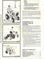
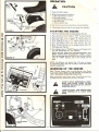
YARD CARE
YOUR NEW GT 18
GARDEN TRACTOR
FEATURES ...
CRAFTSMAN
OVERHEAD
VALVE 18 H.P. ENGINE--coolrunning performance
and long life with plenty of power to
take on a variety of yard, gardening or snow removal tasks.
SAFETY INTERLOCK
SYSTEM--allows
engine to start only
when tractor Clutch-Brake
Pedal is depressed and Attachment
Clutch Pedal is in "OFF" position.
ALL-GEAR TRANSMISSION--six
speeds forward, two reverse
speeds--to let you select the proper match for the terrain and
the job. Auto-type
differential
helps guard against turf scuffing.
CONTROL
PANEL--with
Throttle,
Choke, Light Switch, Ignition Switch, Ammeter
and Electric Lift Switch for Three
Point Hitch conveniently
grouped for ease of use.
ATTACHMENT
VERSATILlTY--handles
a large variety of
Sears Yard and Garden Tractor Attachments
including ...
42 AND 48 INCH MOWERS with three "high-lift" blades
to lift grass up for level cuts.
LITTER WHISK LAWN SWEEPER is more efficient than
conventional
lawn sweepers because of its wheel-less design;
only the rotary brush touches the ground.
SELF POWERED
ROTO-TILLER
prepares soil for new
lawns and gardens with a 30 to 38 inch wide tilling path.
OTHER SOIL TILLAGE ATTACHMENTS
including Plow,
Disc Harrow, Drag Harrow and Cultivator.
CHEVRON TIRES for added traction in loose soil, gravel
or snow.
SNOW BLOWER handles wet, heavy or powdery snow with
ease.
TABLE
OF CONTENTS
WARRANTy
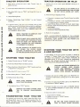
RULES FOR SAFE OPERATION
ASSEMBLY INSTRUCTIONS
OPERATION INSTRUCTIONS
MAINTENANCE INSTRUCTIONS
TROUBLE SHOOTING
REPAIR PARTS
_
1
1
2
4
6
11
12
FULL ONE YEAR WARRANTY
ON ELECTRIC
START GARDEN
TRACTOR
For one year from the date of purchase, when this Garden Tractor is used for personal
material or workmanship
in this Garden Tractor, except the battery, at no charge.
If this Garden Tractor
is used for commercial
FULL
or rental purposes,
90-DAY
For 90 days from the date of purchase, if any battery included
not hold a charge, Sears will replace the battery, at no charge.
LIMITED
this warranty
WAR
ON
the Garden Tractor
WARRANTY
purposes,
applies for only 30 days from
RANTY
with
household
ON
Sears will
repair
any defect
in
the date of purchase.
BATTERY
proves defective
in material
or workmanship
and will
BATTERY
another free manual from www.searstractormanuals.com
From the 91st day until one year from the date of purchase, if any battery included with the Garden Tractor proves defective in material or
workmanship
and will not hold a charge, Sears will replace the battery, charging 1/12th of the price of the new battery for each full month
from the date of purchase.
Warranty service is available at your home, at no charge, by simply contacting the nearest Sears store or Service Center throughout
the United
States.
This warranty gives you specific legal rights, and you may also have other rights which vary from state to state.
Sears, Roebuck and Co.
Sears Tower
SSC 41-3
Chicago,IL
60684
WARNING
This unit is equipped with an internal combustion
engine and should not be used on or near any unimproved
forest-{;overed, brush-{;overed or grasscovered land unless the engine's exhaust system is equipped with a spark arrester meeting applicable local or state laws (if any). If a spark arrester is
used, it should be maintained in effective working order by the operator.
In the State of California
the above is required by law (Section 4442 of the California
Public Resources Code). Other states may have similar
Federal laws apply on federal lands. See your S"ars Authorized
Service Center for spark arrester muffler
part number 6383R.
A
laws.
LOOK FOR THIS SYMBOL TO POINT OUT IMPORTANT
SAFETY PRECAUTIONS. IT MEANS-ATTENTION!
BECOME ALERT! YOUR SAFETY IS INVOLVED.
RULES FOR SAFE
1. Know the controls and how to stop quickly. READ THE
OWNER'S MANUAL.
2. Do not allow children to operate the vehicle. Do not allow
adults to operate it without proper instruction.
3. Do not carry passengers. Keep children and pets a safe distance away.
4. Always wear substantial footwear. Do not wear loose fitting
clothing that could get caught in moving parts.
5. Keep your eyes and mind on your tractor, mower and the
area being cut. Don't let other interests distract you.
6. Do not attempt to operate your tractor or mower when
not in drivers seat.
7. Always get on or off your tractor from the operators left
hand side.
8. Clear the work area of objects which might be picked up
and thrown.
9. Disengage all attachment
clutches and shift into neutral before attempting to start the engine.
10. Disengage power to attachments
and stop the engine before leaving the operator's position.
11. Disengage power to mower, stop the engine and disconnect
spark plug wire(s) from spark plug(s) before cleaning, making an adjustment
or repairs.
12. Disengage power to attachments
when transporting
or not
in use.
13. Take all possible precautions
when leaving the vehicle unattended,
such as disengaging the power-take-off,
lowering
the attachments,
shifting' into neutral, setting the parking
brake, stopping the engine, and removing the key.
14. Do not stop or start suddenly when going uphill or downhill. Mow up and down the face of slopes (not greater than
15°); never across the face.
15. Reduce speed on slopes and make turns gradually to prevent tipping or loss of control.
Exercise extreme caution
when changing direction on slopes.
16. Do not shift gears while going up or down slopes. Choose a
gear low enough to negotiate the slope without
stopping
and shifting gears. To reduce speed, move throttle
lever
to slow.
17. Never mow in wet or slippery grass, when traction is un·
sure or at a speed which could cause a skid.
18. Stay alert for holes in the terrain and other hidden hazards.
19. Do not drive,too
close to creeks, ditches and public high·
ways.
20. Exercise special care when mowing around fixed objects
in order to prevent the blades from striking them. Never
deliberately
run tractor or mower into Or over any foreign
object.
21. Never shift gears until tractor comes to a stop.
22. Never place hands or feet under the mower, in the deflector
(discharge chute) or near any moving parts while tractor or
mower are running. Always keep clear of discharge chute.
OPERATION
23. Use care when pulling loads or using heavy equipment.
a. Use only approved drawbar hitch points.
b. Limit loads to those you can safely control.
c. Do not turn sharply. Use care when backing.
d. Use counterweight
or wheel weights when suggested in
this owner's manual.
24. Watch out for traff:: when crossing or near roadways.
25. When using any attachments,
never direct discharge of
material toward bystanders
nor allow anyone near the vehicle while in operation.
26. Handle gasoline with care - it is highly flammable.
a. Use approved gasoline containers.
b. Never remove the cap of the fuel tank or add gasoline to
a running or hot engine, or fill the fuel tank indoors.
Wipe up spilled gasoline.
c. Open doors if the engine is run in the garage - exhaust
fumes are dangerous.
Do not run the engine indoors.
27. Keep the vehicle and attachments
in good operating condition, and keep safety devices in place.
28. Keep all nuts, bolts and screws tight to be sure the equipment is in safe working condition.
29. Never store the equipment
with gasoline in the tank inside
a building where fumes may reach an open flame or spark.
Allow the engine to cool before storing in any enclosure.
30. To reduce fire hazard, keep the engine free of grass, leaves
or excessive grease.
31. Except for adjustment;
DO NOT operate
Engine if air
cleaner or cover directly over carburetor
air intake is removed. Removal of such part could create a fire hazard.
32. DO NOT OPERATE WITHOUT A MUFFLER
OR TAMPER WITH THE EXHAUST SYSTEM. Damaged mufflers
or spark arresters could create a fire hazard. Inspect periodically and replace if necessarv.
33. The vehicle and attachments
should be stopped and inspected for damage after striking a foreign object, and the damage should be repaired before restarting and operating the
equipment.
34. Do not change the engine governor settings or overspeed
the engine.
35. When using the vehicle
with mower, proceed as follows:
a. Mow only in daylight or in good artificial light.
b. Never make a cutting height adjustment while the engine
is running if the operator must dismount to do so.
c. Shut the engine off when removing the grass catcher or
unclogging chute.
d. Check the blade mounting bolts for proper tightness at
frequent intervals.
36. Check the grass catcher bags frequently
for wear or deterioration. Replace with new bags for safety protection.
37. Do not operate the Mower without either the entire grass
catcher, on mowers so equipped, or the deflector shield in
place.
.
.
,-VEN'C"
To assemble
two 7/16",
and adjust your Tractor
one 9/16"
you will need:
and one 3/4" Wrenches.
NOTE: Right Hand (R.H.) and Left Hand (L.H.) are determined from operator's position while seated on tractor.
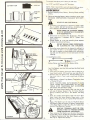
ASSEMBLY
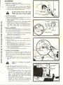
1. Remove Shipping
of Parts.
Wires, Battery,
Steering
Wheel and Bag
2. Filling and charging Battery (before installing). NOTE: SEE
DETAILED
INSTRUCTIONS
PACKAGED
WITH BATTERY.
A
WEAR EYE AND FACE SHIELD.
another free manual from www.searstractormanuals.com
a. Fill Battery with electrolyte
to bottoms of tubes in cells
(Fig. 1). NOTE: DO NOT OVERFILL. OVERFILLING
WILL RESULT IN DAMAGE TO TRACTOR.
WASH HANDS OR CLOTHING
IMMEDIATELY IF ACCIDENTALLY
IN CONTACT
WITH ELECTROLYTE.
A
b. Check level of electrolyte
after 30 minutes. Add additional electrolyte
if necessary.
NOTE: Tighten
Vent
Caps securely.
c. Charge Battery at a rate not exceeding three amperes
for about two and one half hours.
DO NOT SMOKE. FUMES FROM CHARGED ELECTROLYTE
ARE EXPLOSIVE.
d. Neutralize excess electrolyte
for disposal by adding it to
four inches of water in a five gallon plastic container.
Stir with a wooden or plastic paddle while adding baking soda until the addition of more soda causes no more
foaming.
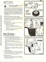
3. Install Battery
using:
6============8
(S'--=-~~-==-==.:::JMii~'
Battery
lJ @~._==~
Clamp, two Wing Nuts, two Battery
Q):::Jm
---5\
Bolts,
®®
four Flat Washers, two Hex Bolts and two Hex Nuts found
in Bag of Parts.
a. Push down and slightly spread rear sides of Hood to release Hood Latches. Lift Hood from rear sides (Fig. 2).
b. Remove tape from Plastic Tray. Position Plastic Tray so
that drain hole in Tray is over round hole of Battery
Support.
c. Place Battery in Plastic Tray (Battery TerrT)inals to front
of Tractor) (Fig. 3).
BATTERY
TERMINAL
HEX
/NUT
NOTE: TIGHTEN
WING NUTS SECURELY
USING
YOUR THUMB AND FOREFINGER.
DO NOT USE
TOOLS.
OVER TIGHTENING
MAY OVERSTR'ESS
OR CRACK THE BATTERY CASE.
d. Hook the curved shank Battery Bolt into slot on the
left side of Battery Support
(Fig. 3). Fasten Battery
Clamp to Battery Bolt with a Flat Washer and Wing
Nut.
e. Hook the straight shank Battery Bolt into slot in R.H.
Hood Latch and fasten Battery Clamp with a Flat
Washer and Wing Nut (Fig. 4). Tighten Wing Nuts securely.
f. Place a Flat Washer over the end of a Hex Bolt. Secure
RED Battery Cable to Positive (+) Battery Terminal with
a Hex Bolt, Washer and Hex Nut (Fig. 5). Tighten Nut
securely. Place Boot over Terminal.
A
POSITIVE
TERMINAL
MUST BE CONNECTED
FIRST TO PREVENT
SPARKS
FROM ACCIDENTAL
GROUNDING.
g. Place remaining Flat Washer over the end of the remaining Hex Bolt. Secure B LACK Ground Cable to Negative
(-) Battery Terminal with Hex Bolt, Washer and Hex
Nut (Fig. 5). Tighten Nut securely.
another free manual from www.searstractormanuals.com
Flat Washer, Lockwasher, and Hex Bolt assembled on end
of Steering Shaft;
Woodruff Key, and Steering Wheel Insert found in Bag of
Parts.
a. Remove Hex Bolt, Lockwasher and Flat Washer from
Steering Shaft (F ig. 6).
b. Insert Woodruff Key in Keyway of Steering Shaft and
slide Steering Wheel over Shaft and Key. NOTE: BE
SURE WOODRUFF KEY IS SECURE IN STEERING
SHAFT.
c. Fasten with Flat Washer, Lockwasher and Hex Bolt (Fig.
6). Tighten securely.
d. Press Steering Wheel Insert in place.
NOTE: A SPARK ARRESTER
MUFFLER
(PAGE 13) IS
AVAI LABLE
AS AN ACCESSORY
PART FOR YOUR
TRACTOR.
CHECK LEGAL REQUIREMENTS
IN YOUR
AREA.
INITIAL
ADJUSTMENTS
1. REDUCE TIRE PRESSURE TO 14 POUNDS IN FRONT
TIRES AND 12 POUNDS IN REAR TIRES. (Tires were
overinflated for shipping purposes).
2. Seat position may be adjusted forward or backward by
loosening Nut in Seat Plate (Fig. 7). NOTE: WHEN RETIGHTENING
NUT AFTER ADJUSTMENT MAKE SURE
SEAT PLATE HAS NOT TWISTED OUT OF ALIGNMENT WITH SEAT SPRING.
INITIAL SERVICE
NOTE: BE CAREFUL NOT TO ALLOW DIRT TO ENTER
THE ENGINE WHEN CHECKING
OR ADDING 01 L OR
FUEL.
THIS
TRACTOR
IS EQUIPPED
WITH
SAFETY
SWITCHES
TO
PREVENT
STARTING
OF THE TRACTOR ENGINE
WHILE
THE
ATTACHMENT
CLUTCH
PEDAL IS IN THE "ON" POSITION (FIG.
10) AND THE CLUTCH-BRAKE
PEDAL
IS IN DRIVE POSITION (FIG. 12).
1. Check Engine Oil Level with Tractor on level ground.
Wipe dipstick (Fig. 8) clean, screw it in tight for a few seconds, remove and read Oil Level. If necessary, add Oil until
"FULL"
mark is reached. In summer use S.A.E. 30 (SC,
SO or SE) Oil. In winter (below 32°F. or O°C.) use S.A.E.
10W30 (SC, SO or SE) or 10W40 (SC, SO or SE). In extreme cold (below O°F. or -17.8°C.) use S.A.E. 5W20 (SC,
SO or SE). NOTE: DO NOT OVERFI LL.
2. Fill Fuel Tank (Fig. 7) with fresh regular grade lead-free or
leaded gasoline. Capacity is 3 - 1/4 gallons. NOTE: DO
NOT SWITCH FROM LEADED TO LEAD-FREE GASOLINE.
FILL TO BOTTOM OF GAS TANK
ER NECK. DO NOT OVERFILL.
OFF ANY SPILLED OIL OR FUEL.
IMMEDIATELY
REPLACE
SWITCHES
THAT ARE NOT IN PROPER WORKING
ORDER. DO NOT ATTEMPT TO DEFEAT
THE PURPOSE OF THESE SWITCHES.
FILLWIPE
_ 3-
1. Keep all shields in place.
2. Before leaving operator's position:
a. Shift transmission to neutral.
b. Set parking brake.
c. Disengage attachment clutch.
d. Shut off engine.
e. Remove ignition key.
3. Wait for all movement to stop before servicing machine.
another free manual from www.searstractormanuals.com
4. Keep people and pets a safe di' tance away from machine.
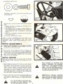
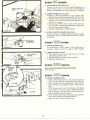
STARTING
THE ENGINE
1. Place Parking Brake Lever in locked position (Fig. 9).
2. Place Attachment
CIUL:, Pedal in "OFF"
3. Place Gear Shift
Lever in neutral "N"
position (Fig.10).
position
4. Move Range Shift Lever to "N"
neutral position
5. Push Clutch-Brake
brake
6. Move Throttle
Pedal into
Control
position
Lever to middle position
(Fig. 11).
(Fig. 11).
(Fig.
12).
(F ig. 13).
7. Pull Choke out (Fig. 13).
8. Turn Ignition Key to "START" position until Engine starts
(Fig. 13). Release key into "ON" position.
NOTE: DO NOT RUN STARTER CONTINUOUSLY
FOR
MORE THAN THIRTY SECONDS AT A TIME. If engine
does not start after several attempts, move Throttle Control
Lever to "FAST"
position, wait a few minutes, and try
again.
NOTE: The Electric Lift Switch (Fig. 13) raises or lowers
an attachment when used with an Electric Three Point Hitch
(optional equipment).
~
0
~
i i :ro
iO
IO-
10
{
-:.::
0
10
RANGE SHIFT
LEVER
0
0
0-
\ HIGH
./
II
NEUTRAL
-J
..:--."..>(.
o"tI,)
~
;
011
II
LOW
o e//
Move Throttle Control Lever to slow position. Push Choke
in as engine warms. NOTE: ALLOW ENGINE TO WARM UP
FOR A FEW MINUTES BEFORE OPERATING.
When restarting a warm engine, move Throttle Control
to middle position, Choke may not have to be used.
Lever
ALWAYS
WEAR SUBSTANTIAL
FOOTWEAR AND AVOID
LOOSE FITTING
CLOTHING THAT COULD GET CAUGHT
IN MOVING PARTS.
LEARN TO START, STOP AND REVERSE
YOUR TR~CTOR
IN A LARGE, OPEN
SPACE.
1. With engine running
middle position.
3. Move Gear Shift
"LOW".
place Throttle
Lever in
Lever to "2N D" and Range Shih Lever to
5. Release Clutch-Brake
movement.
another free manual from www.searstractormanuals.com
and warm,
Pedal SLOWLY
to start
forward
6. If ground travel is too slow move Throttle
Lever to fast
position or press Clutch-Brake Pedal and shiftto a different
gear. NOTE: ALWAYS SELECT A GROUND TRAVEL
SPEED THAT WILL SUIT THE TERRAIN
AND THE
ATTACHMENT
BEING USED.
BRING TRACTOR TO COMPLETE
BEFORE SHIFTING GEARS.
1. Choose one of the lowest gears BEFORE
cdown hills.
starting up or
DO NOT DRIVE UP OR DOWN HILLS
WITH SLOPES GREATER THAN 15~ AND
DO NOT DRIVE ACROSS ANY SLOPE.
a. If slowing is necessary, move Throttle Control to middle
position.
. b. If stopping is necessary, push Clutch-Brake Pedal quickly to brake position to prevent rolling.
c. Lock Parking Brake and shift to lowest speed range.
d. Partially release Clutch-Brake Pedal (until forward movement begins).
e. Unlock Parking Brake.
f. Completely release Clutch-Brake Pedal.
STOP
NEVER PLACE YOUR HANDS OR FEET
IN OR UNDER ANY POWERED ATTACHMENT OR NEAR ANY MOVING PART
WHILE TRACTOR
OR ANY POWERED
ATTACHMENT
IS RUNNING.
DO NOT OPERATE THE MOWER WITHOUT
EITHER
THE
ENTIRE
GRASS
CATCHER, ON MOWERS SO EQUIPPED,
OR THE DEFLECTOR SHIELD IN PLACE.
NOTE: ALWAYS OPERATE ENGINE AT FULL ENGINE
RPM WHEN MOWING TO ASSURE BETTER MOWING PERFORMANCE,
LONG ENGINE LIFE AND PROPER DISCHARGE OF CUT MATERIAL.
STARTING
YOUR
A LOW BATTERY
TRACTOR
WITH
If your Battery is too low to start the engine, it should be
recharged. If "Jumper Cables" are used for emergency starting, follow this procedure:
NOTE: YOUR TRACTOR
IS
EQUIPPED WITH A 12 VOLT NEGATIVE
GROUNDED
SYSTEM. THE OTHER VEHICLE
MUST ALSO BE A 12
VOLT NEGATIVE GROUNDED SYSTEM.
3. Place Attachment Clutch Pedal in "OFF"
er attachment to the grou nd.
position and low-
LEAD-ACID BATTERIES GENERATE EXPLOSIVE
GASSES.
KEEP
SPARKS,
FLAME,
AND
SMOKING
MATERIALS
AWAY
FROM
BATTERIES.
ALWAYS
SHIELD
EYES AROUND
BATTERIES.
1. Connect each end of the RED cable to the POSITIVE (+)
terminals of each battery (taking care not to short against
chassis).
MAKE
SURE PARKING
BRAKE
HOLD TRACTOR SECURE.
REMOVE KEY WHEN
TOR
TO PREVENT
USE.
WILL
LEAVING
TRACUNAUTHORIZED
For pushing and towing your tractor, place Gear Shift Lever
and Range Shift Lever in "N" (Neutral) position (Fig. 11).
NOTE: DO NOT TOW YOUR TRACTOR FASTER THAN
SIX MILES PER HOUR.
_ 5-
2. Connect one end of the BLACK
(-) terminal of "GOOD" battery.
cable to the NEGATIVE
3. Connect the other end of the cable to ENG IN E BLOCK
or good CHASSIS GROUND on tractor (away from Gas
Tank or Battery).
a. Engine Block or Chassis.
b. Negative terminal of "GOOD"
c. Positive term inals.
battery.
DO NOT USE YOUR TRACTOR
BAT-TERy
TO START OTHER VEHICLES.
To keep your tractor running better, longer; perform necessary
service using the following Maintenance Schedule.
Each time you start your tractor, check your Ammeter (Fig.
14), The needle should move towards the + (charging) mark
Indicating the battery is being charged as you operate the
tractor.
DISCONNECT SPARK PLUG WIRES
PREVENT ACCIDENTAL
STARTING
FORE MAKING ANY INSPECTION,
JUSTMENT (EXCEPT CARBURETOR)
REPAIR.
,
another free manual from www.searstractormanuals.com
FLAT
IDLER
FIRST
TO
BE·
AD·
OR
~ HOURS:
1. CHECK V-BELT TENSION
A new V·Belt may stretch after the first few hours of operation, If Clutch-Brake Pedal, in drive position (Fig. 15), is
considerably to the front or rear of the vertical position,
the V-Belt is out of adjustment and must be re-tensioned.
a, Secure Clutch-Brake pedal in brake position (relaxing
V-Belt tension) by tieing to front axle.
b, Hold Nut on inside of Flat Idler and loosen Flat Idler
Bolt.
c, Move Flat Idler in frame slot 1/4 inch down (to tighten),
up (to loosen) V-Belt tension, Tighten Bolt.
d, Release Clutch-Brake Pedal. It should return to approxi·
mately vertical position.
~.::..:~
I
BELT
GUARD
BELT
GUIDE.,
A
CHECK TO MAKE SURE TRACTOR DOES
NOT START WITHOUT FULLY DEPRESSING CLUTCH·BRAKE
PEDAL.
NOTE: FOR LONGER V-BELT LIFE, ALWAYS KEEP
BELT TENSIONED
PROPERLY.
START TRACTOR
MOVEMENT
WITH THROTTLE
CONTROL
IN MIDDLE POSITION, AND ALWAYS REPLACE WITH SIMPSONS-SEARS V-BELTS.
-
2. CHANGE ENGINE OIL
Changing Oil after the first two hours will help eliminate
break-in residue which might be damaging to your Engine.
Note: Be careful not to allow dirt to enter the Engine
when changirtg oil.
a. Drain Oil with Engine warm. Unscrew Oil Drain Cap
(Fig. 16) and catch Oil in a suitable container. Replace
Cap,
b. Refill Engine Oil (Fig. 17). In summer use S.A.E. 30
(SC, SO or SE) Oil. In winter (below 32°F. or O°C.) use
SAE. 10W30 (SC, SO or SE) or 10W40 (SC, SO or SE).
In extreme cold (below O°F. or -17.8~C.) use S.A.E.
5W20 (SC, SO or SE). Capacity is 52 ounces. NOTE:
DO NOT OVERFI LL,
FREQUENTLY
__
1f
II . 1
.
iI' -
i1
•
.
FIGURE
.
VENTeA'
~
.
\
1!
I:
\:
.----U:
18 -~-.;.---
1. CHECK BATTERY
a, Electrolyte solution level in each Battery Cell should be
even with bottoms of tubes in cells (Fig. 18). Add distilled water if necessary, NOTE: DO NOT OVERFILL.
b. Keep Battery and Terminals clean. Refer to page 10.
c, Keep Battery Bolts tight.
d. Keep Vent Caps tight and small Vent Holes in Caps
open.
e. Recharge SLOWLY at 3 amperes if necessary.
:~:y1
..
: ----------
/V
i;
::
"
~,
--i~
BATTERy
TUBE
2. CHECK TIRE PRESSURE
Tire pressure in front Tires should
Tires 12 pounds.
BATTERY
CELL
_6 -
be 14 pounds;
3. CLEAN AIR SCREEN
Air Screen (Fig. 21) must be kept free of dirt
to prevent Engine damage from overheating.
rear
and chaff
·
EVERY ~ HOURS
another free manual from www.searstractormanuals.com
DO NOT CHECK ENGINE
WITH ENGINE RUNNING.
OIL
LEVEL
Several minutes after stopping Engine, check Engine Oil
Level with Tractor on level ground. Wipe dipstick (Fig. 17)
clean, Oil Fill Plug must be seated fully and tightened
and/or locked securely into oil fill hole when checking oil
level. If necessary, add Oil until "FULL"
mark is reached.
In summer use S.A.E. 30 (SC, SO or SE) Oil. In winter
(below 320F. or OOC.) use S.A.E. 10W30 (SC, SO or SE) or
10W40 (SC, SO or SE). In extreme cold (below OOF. or
- 17.80C.) use S.A.E. 5W20 (SC, SO or SE). NOTE: 00
NOT OVERFILL.
2. LUBRICATE STEERING AND FRONT WHEELS
There are six Grease Fittings on your Tractor (Fig. 19).
Using a Grease Gun, give each Grease Fitting two shots of
Extreme Pressure Lubricating Grease Amdex No. 1 (available through your Sears store).
3. OIL PIVOT POINTS
Place several drops of S.A.E. 30 Oil at points where parts
move against each other, especially:
a. Idler Bearing (Fig. 15).
-- Remove Idler Bearing Cap.
Remove Retainer Spring from Idler Shaft.
-- Move Idler and Shaft outward and lubricate exposed Shaft.
-- Return Idler and Shaft to original position, replace
Retainer Spring and reposition Cap.
b. Front Axle Pivot (Fig. 19).
EVERY
~~
HOURS
(EVERY 15 HOURS IF OPERATING
IN VERY DUSTY CONDITIONS)
1. CLEAN AIR FILTER & FOAM PRE-CLEANER
a. Unscrew Wing Nut (Fig. 20) to remove Air Filter Cover,
Paper Air Filter Element and Foam Pre-Cleaner.
b. Clean dust from Paper Air Filter Element by gently tapping Element on a flat surface.
,c. Wash Foam Pre-Cleaner in detergent and water.
d. Rinse, squeeze (rather than twist) and allow to dry thoroughly.
e. Coat with three tablespoons of S.A.E. 30 Engine Oil,
knead to distribute
evenly, and squeeze out excess.
f. Check Paper Air Filter Element. Replace if excessively
dirty.
-.
g. Re-assemble Air Filter and re-position
on Tractor.
NOTE: NEVER RUN ENGINE WITH AIR CLEANER
REMOVED.
2. CLEAN AIR SCREEN
Air Screen and Guard (Fig. 21) must allow free-flow of air
to prevent Engine damage from overheating. Remove Air
Screen and Guard and clean with a wire brush to remove
dirt and chaff and stubborn dried gum and fibers.
3. CHANGE ENGINE OIL
The best time to change Engine Oil is at the end of a days
operation when all dirt and foreign material is suspended
in the hot Oil. Refer to page 6.
o
r
STEERING GEAR
SECTOR AND
ARM GREASE
FITTING
~~
11-
~
STEERING
BELLCRANK
GREASE
FITTING
FRONT SPINDLE
GREASE FITTING
(LEFT & RIGHT)
EVERY
1. CLEAN
Remove
prevent
Housing
another free manual from www.searstractormanuals.com
ENGINE COOLING
FINS
~@
HOURS
ENGINE COOLING FiNS
any dust, dirt or oil from Engine Cooling Fins to
Engine damage from overheating. Remove Blower
and Shielding and clean areas shown in Fig. 22.
2. CHECK TRANSAXLE
OIL LEVEL
a. Block up Rear Axle securely or use a Tractor Jack.
Remove left rear wheel by removing Klip Ring (Fi£. 32).
b. Remove Filler Plug (Fig. 23) from Transaxle. Oil Level
should be even with Filler Plug threads. Add S.A.E. 30
Motor Oil if necessary.
c. Check Pressure Relief Valve located on R.H. side near
top (Fig. 25). It should spring completely closed when
pulled out by hand and released.
d. Reposition wheel. Secure with Klip Ring.
3. SPARK ARRESTER EQUIPPED MUFFLER
If engine muffler is equipped with spark arrester muffler,
remove every 50 hours for cleaning and inspection. Replace
if damaged.
TRANSAXLE
FILLER PLUG
EVERY
TI@@
HOURS
1. REPLACE SPARK PLUG
At the beginning of each season or every 100 hours of
operation, which,o:ver comes first. Gap at .030" (Fig. 24).
2. LUBRICATE BALL JOINTS
a. Move Rubber Boots to expose Ball Joints on Tie Rods
and Steering Link (Fig. 27).
b. Coat Ball Joints with Silicone Spray Lubricant.
c. Reposition Rubber Boots.
EVERY
~@@
REPLACE AIR CLEANER
Refer to page 7.
EVERY
tD@@
HOURS
PAPER CARTRIDGE.
HOURS
1. CHANGE TRANSAXLE OIL
a. Block up Rear Axle securely or use a Tractor Jack. Remove Left Rear Wheel by removing Klip Ring (Fi9. 32).
b. Drain Transaxle Oil by removing Drain Plug (Fig. 25)
and catching Oil in a suitable container. Replace Drain
Plug.
c. Refill Transaxle with S.A.E. 30 (SC, SD or SE) Motor
Oil. Capacity is 5 quarts. Pressure Relief Valve (R.H.
side of Transaxle, Fig. 25 - Inset) may be held open to
allow Transaxle to fill more quickly.
d. Check Pressure Relief Valve. It should spring completely
closed when pulled out by hand and released.
e. Reposition wheel. Secure with Klip Ring.
1. REPLACE IN-LINE FUEL FILTER
If fuel filter is clogged, obstructing fuel flow to carburetor,
replacement is required.
a. With Engine cool, remove and plug Fuel Line Sections
as removed from both ends of Fuel Filter (Fig.26).
b. Place new Fuel Filter in position in Fuel Line (arrow
on side of Filter in direction of fuel flow).
another free manual from www.searstractormanuals.com
BE SURE THERE ARE NO FUEL LINE
LEAKS AND THAT FUEL LINE IS IN
PROPER POSITION IN HOSE CLAMPS.
2. TOE-IN ADJUSTMENT
If any parts in Front Axle or Steering Mechanism are being
replaced, Tie Rod adjustment is required.
a. Loosen Jam Nuts (Fig. 27) at each end of Tie Rod Adjustment Sleeves.
b. Adjust both Tie Rods so that Tie Rod Joints measure
from 10 to 10 - 1/8 inches from center to center.
c. Tighten Jam Nuts, making sure Tie Rod Joints are parallel (180°) to each other. This adjustment secures
proper Front Wheel Toe-in and steering operation.
3. BRAKE ADJUSTMENT
If Clutch-Brake Pedal (Fig. 28) has more than approximately 4 inches of travel from vertical to full brake position
then brake adjustment is necessary.
a. Loosen Nut (Fig. 28) in order to turn turnbuckle clockwise (from in front of tractor) one turn at a time until
Clutch-Brake Pedal regains 4 inches of travel.
b. Tighten Nut against Turnbuckle.
4. PARKING BRAKE ADJUSTMENT
If Parking Brake will not hold tractor, Parking Brake adjustment is necessary.
a. Loosen Parking Brake Hex Nuts Second and First
(Fig. 28).
b. Place Parking Brake Lever in locked position.
c. Hold Clutch-Brake Pedal in brake position and tighten
First Hex Nut finger tight against Bushing.
d. Release Clutch-Brake Pedal and turn First Hex Nut two
turns more against Bushing.
e. Tighten Second Hex Nut against First Hex Nut.
5. CARBURETOR ADJUSTMENT
The carburetor on this engine is equipped with a non-adjustable main fuel mixture jet which in most cases will
eliminate the need for carburetor adjustments. If the engine
does not idle properly, the idle fuel mixture needle may
need adjustment.
a. Turn idle adjustment needle (Fig. 29) clockwise closing
finger tight ONLY. Then turn counterclockwise one
turn.
REFER TO "STARTING
PAGE 4.
THE ENGINE"
b. Start engine and allow to warm for five minutes.
c. Make final adjustment with engine running and throttle
control in slow position. Gear shift lever should be in
neutral position.
-- Turn idle adjusting needle 1/8 of a turn at a time
counterclockwise
until engine runs "rou~h", then
clockwise until engine again runs "rough '. Return
screw to a point midway between these extremes.
NOTE: ALLOW SEVERAL SECONDS BETWEEN
EACH ADJUSTMENT
SO THAT THE ENGINE
MAY REACT TO EACH SETTING.
Throttle stop screw (Fig. 29) should not require adjustment. If resetting is necessary, set to obtain the
slowest engine speed at idle (throttle control in
slow position) that will allow smooth acceleration.
TRACTOR
FRAME
~
:\
~
6. RE-TENSION V-BELT
It may be occasionally
page 6).
{0(
t;1
A
BELT
CLUTCHBRAKE
another free manual from www.searstractormanuals.com
"""'--'=-----
---------PEDAL
TRANSMISSION
PULLEY
KLIPRING,\
necessary
to re-tension
V-Belt. (See
CHECK TO MAKE SURE TRACTOR DOES
NOT START WITHOUT FULLY DEPRESSING CLUTCH-BRAKE
PEDAL.
7. V-BELT REPLACEMENT
a. Remove Belt from Clutch Idler by depressing ClutchBrake Pedal (Fig. 311.
b. Remove Belt Guide from Engine Pulley.
c. Remove Rear Belt Guide Assembly from Transmission
Pulley.
d. Loosen Flat Idler Assembly on R.H. side of Tractor
Frame.
e. Remove Belt from Engine Pulley, between Belt Guide
Finger (note position of Belt) and Flat Id.ler, and Transmission Pulley.
f. Place new Belt around Transmission
Pulley. Then place
Belt between Belt Guide Finger and Flat Idler and then
around Engine Pulley.
g. Depress Clutch-Brake
Pedal and slip Belt over the top of
the Clutch Idler.
h. Replace Engine Pulley Belt Guide and Transmission
Pulley Belt Guide. Tighten Flat Idler Assembly.
NOTE:
Make sure Belt Guide Finger on Flat Idler is parallel
with slot in Tractor Frame.
i. Check Belt tension, page 6.
8. CLEAN BATTERY AND TERMINALS
Corrosion
and dirt on the Battery and Terminals cause
the Battery to "leak" power and hinders the operation of
the charger.
a. Remove the Battery from the Tractor and wash with
four tablespoons
of baking soda to one gallon of water.
NOTE:
BE CAREFUL
NOT TO GET THE SODA
SOLUTION
INTO THE CELLS. Rinse the Battery with
plain water, dry and reinstall on Tractor.
b. Clean Terminals and Battery Cables with a wire brush
until bright. Replace Battery Cables. Coat terminal connections with Vasoline.
r----..
9. TIRE CARE
a. Maintain tire pressure of 14 pounds in front tires and
12 pounds in rear tires.
b. Keep tires free of gasoline, oil, or insect control chemicals which can destroy rubber.
c. Avoid stumps, stones, deep ruts and other hazards that
may cause tire damage.
d. Removing front wheel for tire repair (Fig. 31).
-- Block up front axle securely or use a Tractor Jack.
-- Remove Hex Bolt and Dust Cap.
-- Remove Nut, Wear Washer, Pin and Washer to allow
wheel removal.
-- Repair tire and reassemble.
e. Removing rear wheel for tire repair (Fig. 32).
-- Block up rear axle securely or use a Tractor jack.
-- Remove Klip Ring to allow wheel removal .
.- Repair tire and reassemble. Snap Klip Ring securely
in axle groove.
10. FINISH
Keep tractor finish and tractor seat free of gasoline, oil,
insect chemicals
or battery
electrolyte.
Protect
painted
surfaces with automotive
type wax.
~
TROUBLE
SHOOTING
POSSIBLE CAUSE
WILL NOT START
Clutch-Brake Pedal in drive position
Attachment Clutch Pedal in "ON" position
No gasoline in Fuel Tank, clogged Fuel Filter
or Fuel Line
Blown Fuse
Dead Battery
another free manual from www.searstractormanuals.com
HARD TO START
Choked improperly,
flooded Engine
Clogged Fuel Filter
Clogged Fuel Tank
Dirty Air Cleaner
Spark Plug dirty or improper gap
Defective Battery
Defective Ignition or loose wiring
Water in gasoline or old fuel
Improper Carburetor adjustment
Press Pedal into brake position (Fig. 12)
Move Pedal to "OFF" position (Fig. 10)
Fill Tank with Gasoline, check Fuel Line, Fuel Filter
and Carburetor (clean if necessary)
Check for fault and replace Fuse
Recharge or replace Battery
Push Choke in, place Throttle Control in middle position
and run starter several times to clear out gas (Fig. 13)
Remove and replace (Fig. 26)
Remove and clean
Remove and clean (Fig. 20)
Replace Spark Plug (Fig. 24)
Recharge or replace
Check the wiring and Spark Plug
Drain Fuel Tank and Carburetor, use fresh fuel and clean
Spark Plug
Make necessary adjustments (Fig. 29)
ENGINE MISSES OR LACKS POWER
Engine overload
Clogged Fuel Filter
Clogged Fuel Tank
Partially plugged Air Cleaner
Improper Carburetor adjustment
Dirty Air Screen
Low oil level or dirty oil
Spark Plug dirty, improper gap or wrong type
Faulty ignition
Poor compression
Oil in gasoline
Shift to a lower gear (Fig. 11) or reduce load
Remove and replace (Fig. 26)
Remove and clean
Remove and clean (Fig. 20)
Make necessary adjustments (Fig. 29)
Clean Air Screen and Cylinder Fins (Fig's. 21 and 22)
Add or change oil (Fig's. 16 and 17)
Replace Spark Plug (Fig. 24)
Check Spark Plug and for loose wires
Major Engine overhaul
Drain and refill Gas Tank and Carburetor
ENGINE OVERHEATS
Dirty Air Screen
Low oil level or dirty oil
Dirty Engine
Partially plugged Muffler
Partially plugged Air Cleaner
Stale fuel or improper Carburetor adjustment
Clean Air Screen (Fig. 21)
Add or change oil (Fig's. 16 and 17)
Clean Cylinder Fins (Fig. 22)
Remove and clean Muffler
Remove and clean (Fig. 20)
Use fresh fuel and adjust Carburetor (F ig. 29)
NO LIGHTS
No Headlights or Taillight
pulled out
Check Fuse, Wire Connections and Switch. Replace Taillight Bulb or Sealed Beam Headlights
with Light Switch Knob
WON'T CHARGE
Blown Fuse
Defective Battery
1. ENGINE OIL
Drain (with engine warm) and replace with clean engine oil.
Refer to page 6.
2. FUEL SYSTEM
a. Drain fuel tank and carburetor by allowing the engine to
run out of gasoline. NOTE: GASOLINE
LEFT IN
YOUR
ENGINE
WILL
LEAVE
GUM DEPOSITS
CLOGGING FUEL SYSTEM.
b. Dispose of gasoline if not to be used. NOTE: GASOLINE STORED
FOR SEVERAL
MONTHS
LOSES
ITS VOLATILITY
(ABILITY
TO BURN EFFECTIVELY).
Check for fault and replace
Replace
4. BATTERY
a. Remove battery if tractor is not used regularly during
winter months. Store in cool, dry place (above 50°F.).
NOTE: DO NOT STORE BATTERY
DIRECTLY
ON
CEMENT SURFACE.
b. Recharge each month if necessary. NOTE: BATTERIES
NOT IN USE FOR SEVERAL
MONTHS AND NOT
KEPT FULLY CHARGED, PRODUCE SULPHUR DEPOSITS ON PLATES WHICH CANNOT BE: REMOVED
BY RECHARGING.
5. GENERAL CLEANING
Clean engine, battery, seat, finish,
ter.
etc. of all foreign mat-
3. CYLINDER
a. Remove Spark Plug.
b. Pour one ounce of oil through spark plug hole into cySears, Roebuck and Co. reserves the right to make any changes
linders.
in design or improvements without imposing any obligation to
c. Turn ignition
key to "START"
position for a few
insti:lll the same upon its items heretofore manufactured.
seconds to distribute oil.
d. Replace Spark Plug.
_ 11 _
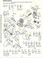
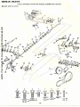
18 H.P. GARDEN TRACTOR--MODEL
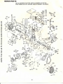
NUMBER 917.257120
MAIN FRAME, DASH AND GRILL
ABC
E
F
i 1'20
=78
c:S=>
79
33
tr.D 80
=
<:=:>
1
6
96
96
[J1
97
another free manual from www.searstractormanuals.com
lIJJ 97
<:=:>
42
J
K
L
1126
11221120
~96=91
96[]) 97=
~
91
c=. 86
86
c::3=
U
v
y
W
Z
II
,06'06 if
1
1,02 • 95 1"104
=91=98
== 86=98
~96
93 [J) 97
lTIJ
AA
~
107lED 109
BB
g
-12 -
=98
0=
96
rID
97
93
<:=:>
9a
1'2
=
86
93
HH
FF
121
lI1)117
'120
lIJJ
(I] 97[[]
EE
DO
=
111
110
1115
~112
= 113
79
[]] 114
a::Il 80
=
=0 96
74c::= 98 ~
96
==96 =
6
[J) 97 ;-:1 97
CC
93
99195192
1941132195195
[§JJ
rIll
79
~
,
85
cs=:>
86
-:;
REPAIR PARTS
18 H.P. GARDEN TRACTOR--MODEL NUMBER 917.257120
MAIN FRAME, DASH AND GRILL
another free manual from www.searstractormanuals.com
r
r----,
~
.--
KEY
NO.
PART
NO.
1
2
3
4
5
6
7
8
9
10
11
12
14
15
16
17
18
19
21
22
23
911J
2872J
6106R
1733J
2794R
1557P
290J
7937R
7938R
2674R
2673R
STD522507
634A901
89J
92J
93J
91J
267J
7900R
7899R
673A285
24
26
27
28
29
30
31
32
33
34
35
36
37
38
39
40
41
42
43
45
46
47
48
49
50
51
52
53
9396E
634A104
673A289
8704H1
4939M
9011H
634A660
8238H
50P
1545P
STD561210
634A900
8457R
673A283
7756R
8006R
7905R
1598J
634A902
634A785
7944R
7948R
7810H
634A814
634A787
634A355
8591R
3052J
55
56
57
58
59
61
62
63
64
65
66
67
68
69
70
1596R
673A268
6468H
4766H
673A282
8205R
8204R
1550J
634A893
106J
1998R
8571 R
2773J
7874R
8855R
DESCRIPTION
Grill - Upper
Decal- Grill
Cable Tie
Decal - Hood, L.H., Rear
Grill Screen - Center
Washer 13/32 x 13/16 x 11 Ga.
Grill Panel - Upper
Grill- Lower
Grill Side
Grill Screen - L.H.
Grill Screen- R.H.
* Hex Bolt 1/4 - 20 x 3/4
Attachment Clutch Pedal Weldment
Link
Speed Nut - Push-On
Rubber Pedal
Pivot Spacer
Foot Pedal
Grill Cable
Grill Brace
Engine, Craftsman 18 H.P.
Model No. 143.700012
Sq. Key 1/4 x 2
Engi ne PuIley (I nc. 2 ea. Key No. 94)
Belt Guide Weldment
Spacer
Retainer Spring
Belt Retainer
Belt Guard Weldment
Split Spacer
Sq. Neck Carriage Bolt 3/8 - 16 x 2·1/4
Washer 17/32 x 1 x 16 Ga.
*Cotter Pin 1/8 x 1
Hood Latch Assembly
Bumper
Battery Support Bracket (Inc. Key 39)
Bearing
Cap
Cover- R.H.
Decal- Grill- R.H.
Lever Weldment
Hanger Weldment R. H. - Front
Belt Tightener Arm
Return Spring
Locknut 3/8 - 24 UNF
Hanger Weldment - Rear
Drawbar and Weldnuts
Hanger Weldment - L.H. - Front
Choke Control
Throttle Remote Control (Inc.
Key 61,62 &63)
Decal - Shift Pattern
Chassis Ass'y. (Inc. Key 57 & 58)
Bearing - Upper
Bearing - Lower
Engine Mount Ass'y.
Throttle Wire & Casing
Clamp
Throttle Control Knob
Dashboard (Inc. Key No's. 66 & 67)
Battery Support
Clip - Dashboard, Side
CI ip - Dashboard, Center
Battery Heat Shield
Hood Seal
Battery Tray
- 13 -
KEY
NO.
PART
NO.
71
72
73
74
75
76
78
79
80
81
3051J
112J
1181J
1685H
634A680
8028R
1599J
STD551025
STD551125
STD541025
STD601003
82
83
85
86
87
STD522515
1605H
STD523107
STD551131
STD611005
91
92
93
94
STD551031
STD523112
STD541031
4546P
95
96
97
98
99
STD523710
STD551137
STD541037
STD551037
3154P
100
102
104
347J
STD533107
5557P
105
STD533710
106
107
108
109
110
3035P
STD551143
STD523707
5394H
6055P
111
112
113
114
115
117
120
121
122
123
124
125
126
127
128
130
132
53P
1535P
STD551110
STD541010
STD522505
STD541137
STD523712
1402P
3022P
8768H
9878R
1732J
STD523110
2949R
3058J
7830R
STD523108
77
DESCRIPTION
Cover - L.H.
Bracket· Battery Support
Bracket - Rectifier
Locknut 5/16 - 18 UNC
Hood Ass'y.
Decal - Maintenance
Decal - Grill- L.H.
*Washer 9/32 x 5/8 x 16 Ga.
*Lockwasher 1/4
*Hex Nut 1/4 - 20 UNC
*Phillips Pan Hd. Thd. Self Tap.
10 - 24 x 3/8 Type T
* Hex Bolt 1/4 - 20 x 1 - 1/2 Grade 5
Locknut 1/4 - 20 UNC
*Hex Bolt 5/16 - 18 x 3/4 Gr. 5
* Lockwasher 5/16
*Phillips Pan Hd. Thd. Self Tap.
10 - 16 Hi-Lo Thd. x 1/2
*Washer 11/32 x 11/16 x 16 Ga.
*Hex Bolt 5/16 - 18 x 1 - 1/4
*Hex Nut 5/16-18
UNC
Socket Hdless. Set Screw
5/16 - 18 x 1/2
* Hex Bolt 3/8 - 16 x 1
* Lockwasher 3/8
*Hex Nut 3/8 - 16 UNC
*Washer 13/32 x 13/16 x 16 Ga.
Sit. Fil. Hd. Machine Screw
1/4-20x2-1/4
Huglock Nut 1/4 - 20 UNC
* Carriage Bolt 5/16 . 18 x 3/4
Hex Washer Hd. Tapping Screw
1/4·20 x 1/2 Type 1
*Sq. Neck Carriage Bolt - Short Shoulder
3/8 - 16 x 1 Gr. 5
Hex Bolt 7/16 - 14 x 1 - 1/4
* Lockwasher 7/16
* Hex Bolt 3/8 - 16 x 3/4
Locknut 3/8 - 16 UNC
Hex Sit. Hd. Machine Screw w/Sems
Int. Tooth Lockwasher 10 - 32 x 1/4
Sq. Neck Carriage Bolt 10 - 24 x 1/2
Washer 7/32 x 7/16 x 18 Ga.
* Lockwasher No. 10
*Hex Nut 10 - 24 UNC
* Hex Bolt 1/4 - 20 x 1/2
* Hex Nut 3/8 - 24 UNF
*Hex Bolt 3/8 - 16 x 1 - 1/4 Gr. 5
Ext. Tooth Lockwasher - 3/8
Hex Bolt 3/8 - 16 x 7/8
Mounting Clip
Decal - Wiring
Decal - Hood, R.H., Rear
*Bolt, Hex 5/16 - 18 x 1
Gasket
Muffler
Grommet
*Bolt, Hex 5/16 - 18 x 7/8
OPTIONAL
Spark Arrestor
EQUIPMENT
Muffler
6383R
37--===-~ ~
38
36/
~
another free manual from www.searstractormanuals.com
41
'{}"L
J..
R
45
5
~6
@c
39
~
~c
A
8
i"Y
=47
lHJ 49
~
[])
~
F
i
~
53
(H]
49
G
H
J
58 ~59Y60
I
~60
3
[])
3
[])
I
53
~
~
61 ~
(I1]
I;: ! i
M
N
P
7:
IT"'T'\
~
2
7
[])53
~
K
L
'63
~55
=,64
65
61 CllJ 66
62
=
R
Q
46
3
[])53
C:'
'ill' Y
I ~
==
74
56
57
75
==:=l'76
~
77
u=r:
78
I)
rr.:;n
~
49
S
T
1 TI
79
~
57
=
83
65
rrI1 66
-7
-8
-7
another free manual from www.searstractormanuals.com
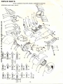
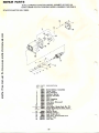
18 H.P. GARDEN TRACTOR--MODEL NUMBER 917.257120
STEERING, AND FINAL DRIVE
~
KEY
NO.
PART
1
1A
2
3
4
5
6
7
8
9
10
11
12
13
14
15
16
17
18
19
20
21
22
23
24
25
26
27
28
29
30
31
32
33
34
35
36
37
38
39
40
41
42
43
44
45
641J
1600J
STD523710
STD551137
1559P
4820R
5003P
9007H
5949H
7903R
8900R
7904R
1553P
9858M1
634A626
6364H
6442H
2511P
634A22A
6477H
9594R
8674R
3802J
795R
9528R
9428R
634A692
7563R
5845R
9427R
2656R
125J
126J
8141H
7898R
634A776
634A532
7897R
1677J
2329J
7885R
6999R
2751 R
897J
2887J
9297R
DECRIPTION
NO.
Steering Wheel Insert
Decal - Sears
* Hex Bolt 3/8 - 16 x 1
* Lo<;:kwasher 3/8
Washer7/16x
1 x 10Ga.
Steering Wheel
E-Ring
Cap
Rubber Bushing
Foot Rest - L.H.
Decal (Attach. Clutch)
Foot Rest - R.H.
Washer 57/64 x 1 - 1/4 x 16 Ga.
Woodruff Key 3/16 x 5/8
Steering Shaft and Pinion
Control Knob
Shift Rod Bracket
Cotter Pin 3/16 x 1
Belt Guide - Transaxle
Range Shift Rod
Bracket - Transaxle
Seat Stop
Rear Tire
Tire Valve
Rear Wheel 12 x 7 JA
Fender - R.H.
Rear Wheel Hub and Bushing
Axle Thrust Washer
Klip Ring
Fender - L.H.
Bracket - Taillight
Seat Stop Bracket
Fuel Tank Retainer
Seat Spring Reinforcement
Seat Spring
Seat Plate Weldment
Seat Bracket Weldment
Bracket, Seat Pivot
Seat
Fuel Gauge
Fuel Tank
Fuel Line Clamp
Clip - Fuel Line
Fuel Line
Filter - Fuel
Clip - Fuel Line
KEY
NO.
PART
NO.
46
61P
47
49
50
51
STD551037
5394H
STD523712
633X18
53
54
55
56
57
58
59
60
61
62
63
64
65
66
70
STD541037
STD523715
3022P
STD523107
STD551131
STD533707
1304H
3034P
STD551143
STD541043
STD522507
STD551025
STD551125
STD541025
STD533107
71
72
73
74
75
76
77
78
79
80
82
83
84
85
STD551031
1685H
STD523707
STD535012
1578P
1560P
STD551150
STD541050
STD523108
9547R
124J
STD522506
3053J
3054J
3019J
53J
3050J
*STANDARD
DESCRIPTION
Sq. Nk. Sht. Carr. Bolt 3/8 - 16
x 1 Gr. 5
*Washer 13/32 x 13/16 x 16 Ga.
Locknut 3/8 UNC
*Hex Bolt 3/8 - 16 x 1 - 1/4
Transaxle (See Pages 20 & 21 for
parts break down)
* Hex Nut 3/8 - 16 UNC
* Hex Bolt 3/8 - 16 x 1 - 1/2
Hex Bolt 3/8 - 16 x 7/8
* Hex Bolt 5/16 - 18 x 3/4
* Lockwasher 5/16
* Sq. Neck Carriage Bolt 3/8 - 16 x 3/4
Hub Bolt
Hex Bolt 7/16 - 14 x 1
* Lockwasher 7/16
*Hex Nut 7/16 - 14 UNC
* Hex Bolt 1/4 - 20 x 3/4
*Washer 9/32 x 5/8 x 16 Ga.
* Lockwasher 1/4
* Hex Nut 1/4 - 20 UNC
* Short Shoulder Sq. Neck Carriage
Bolt 5/16 - 18 x 3/4
*Washer11/32x
11/16x 16Ga.
Locknut 5/16 - 18 UNC
* Hex Bolt 3/8 - 16 x 3/4
* Carriage Bolt 1/2·13 x 1 - 1/4 Gr. 5
Washer 3/4 x 1 . 1/8 x 11 Ga.
Washer 17/32 x 1-1/2x
11 Ga.
* Lockwasher 1/2
*Hex Nut 1/2 - 13 UNC
*Hex Bolt 5/16 - 18 x 7/8
Rubber Grommet
Rubber Bumper
* Bolt, Hex 1/4 - 20 x 5/8
Insulator- Foot Rest
Insulator'- Foot Rest
Tag - Sound Rating
Warranty Tag
Owners Manual
HARDWARE--PURCHASE
LOCALLY
REPAIR
PARTS
another free manual from www.searstractormanuals.com
,
18 H.P. GARDEN TRAC
BRAKE AND CLUTCH
TOR--MODEL NUMBER 917.257120
=66
67
ern
REPAIR
PARTS
18 H.P. GARDEN TRACTOR--MODEL
NUMBER 917.257120
BRAKE AND CLUTCH
§ o6/!/}/
l
another free manual from www.searstractormanuals.com
KEY
NO.
~
1
2
3
4
5
6
7
8
9
10
11
~2
14
15
16
17
18
19
20
21
22
23
24
25
26
27
28
29
30
31
32
33
34
35
36
36A
PART
NO.
8899R
8882R
8765H
9008H
2776J
5023P
1527P
2505P
2202R
6417H
STD541037
7823R
2201 R
1557P
2263R
9686R
175H
634A887
2221R
5999H
4379H
626A341
7810H
626A365
634A 167
634A168
9204H
214J
634A899
9858M1
9288R
2514P
6486H
1648P
4939M
544J
DESCRIPTION
Insert - Clutch/Brake
Foot Pedal
Foot Pedal Bracket
Spring
Foot Pedal Shaft
Klip Ring
Washer 21/32 x 7/8 x 16 Ga.
Cotter Pin 1/8 x 3/4
Brake Rod· Front
Turnbuckle
"Hex Nut 3/8 -16 UNC
Safety Switch Actuator
Bushing
Washer 13/32 x 13/16 x 11 Ga.
Spring Washer
Parking Brake Yoke
Roll Pin
Lock Bracket Assembly
Spacer
Spring Washer
Handle Grip
Parking Lock Handle Assembly
Locknut 3/8 - 24 UN F
Brake Rod Assembly
Brake Band Assembly
Brake Bracket Assembly
Locknut 1/2 - 20 UNF
Brake Drum
Brake Arm Assembly
Woodruff Key
Clutch Rod
CotterPin~
Spring
Washer 17/32 x 1 - 1/16 x 20 Ga.
Retainer Spring
Hose Shield
KEY
NO.
PART
NO.
37
38
39
40
41
42
43
44
45
46
673A259
6636H
5025P
634A898
STD541043
STD551143
1544P
6635H
1639P
6479Hl
~
- 48
49
50
51
52
53
54
55
56
57
58
59
60
61
62
63
64
65
66
67
68
69
-.
DESCRIPTION
Idler Bracket Assembly
Idler
Klip Ring
Steering Arm Weldment
*Hex Nut 7/16 - 14 UNC
* Lockwasher 7/16
Washer 15/32 x 15/16 x 16 Ga.
Flat Idler
Washer 15/32 I.D. xl - 1/8 x 11 Ga.
Belt Guide Finger
32:2P .._._.._.=::.J~.9_l!._7/16'
14 x 2·1/2
6474H
V'Be~~;l/1
64 1H2
e,
ransax e--/,.
STD522507 *Hex Bolt 1/4·20 x 3/4
STD551125 * Lockwasher 1/4
STD623710 *Fin. Hex Bolt 3/8 - 24 x 1
STD551037 *Washer 13/32 x 13/16 x 16 Ga.
STD541337 *Hex Jam Nut 3/8 - 24 UNF
Roll Pin
5142H
3022P
Hex Bolt 3/8·16 x 7/8
STD551137
* Lockwasher 3/8
Flat Hd. Machine Screw· Undercut
3164P
3/8 - 16 x 3/4
l1P
Sq. Neck Carriage Bolt 1/4 - 20 x 5/8
STD541025 *Hex Nut 1/4·20 UNC
STD523108 *Hex Bolt 5/16·18 x 7/8
Locknut 5/16 - 18 UNC
1685H
3244P
Hex Bolt 1/4·28 x 5/8 Gr. 5
9071H
Locknut 1/4 . 28 UNF
3326P
Hex Hd. Mach. Screw 6 . 32 x 1
1567P
Washer 5/32 x 3/8 x 20 Ga.
562P
Centerlock Nut 6 - 32 UNC
Woodruff Key
2228M
1602P
Washer 13/32 x 5/8 x 11 Ga.
"pi
*STANDARD
HARDWARE··PURCHASE
LOCALLY
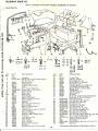
BATTERY
1112V
STARTER
S
"'another free manual from www.searstractormanuals.com
NEUTRAL
IGNITION
SWITCH
SAFETY
SWITCH
"'-
0---/
r '
~
S
"'-
,
SOLENOID
ATTACHMENT
SAFETY SWITCH
PROTECTION
RESISTOR
SOLID
STATE
IGNITION
CHARGING
COIL
HEADLIGHT
FUSE
15 AMP.
POSITION
CIRCUIT
OFF
M-G
ON
B-L
START
B-S
UP-DOWN
SWITCH
1
LIFT
(M'MOTOR
.,
ACCESSORY
CHASSIS
GROUND
If Insulated Clips and Cable Ties were removed for rewiring of unit, they should be replaced to properly
cable.
secure your wiring and
another free manual from www.searstractormanuals.com
~
)
~63
19
B
A
'1
46
[l) 48
,
49
,-=E
0
C
~47
~52
lIIl53
~
50
([])51
CIIJ
G
F
AI'V
54
55
'62
8
a::n
c::=lI:)
52
56
H
lIIl 53
=36
~
52
CIIl 53 -
L
57
58
58
=59
58
51
~
50
cr:D 51
=59
c::::e:>
52
eLl) 5&
a::D 56
KEY
NO.
1
2
PART
NO.
6452R
STD611005
3
4
5
6
7
8
9
10
lOA
11
12
13
14
15
16
17
18
19
20
21
22
23
24
26
27
28
29
30
32
33
8768H
8784H 1
8031 R
9197H
3748M
STD551025
7955R
2685R
88J
4171R
8859R
2235R
7755R
7754R
8027R
116J
225J
8030R
8089H
8292H
8293H
8291H
9433R
7794R
7793R
2212R
6347R
2753R
7552H
4406R
DESCRIPTION
Headlight
* Phillips Pan Hd. Self Tapping Screw
No. 10 - 16 x 1/2
Mounting Clip
Rubber Spacer
Headlight Ground Wire
Hose
Wing Nut 1/4 - 20 UNC
*Washer 9/32 x 5/8 x 16 Ga.
Battery Clamp
Battery Bolt
Battery Bolt
Insulated Clip
Battery "Die Hard
Cable - Solenoid to Starter
Safety Switch
Solenoid
Wire - Ground to Solenoid
Battery Cable
Battery Terminal Cover
Light Harness
Taillight (Inc. Key No. 21, 22, 23)
Lens - Taillight
Housing· Taillight
Bulb No. 18952 Candle Power
Ammeter
Light Switch Knob
Light Switch
Fuse· 15 Amp.
Fuse - 30 Amp.
Battery Cable - Ground
Key Set
Ignition Switch (Inc. Key No. 32)
KEY
NO.
34
35
36
37
38
39
40
41
42
43
44
45
46
PART
NO.
8657R
3055J
1583P
9698R
8984R
566P
7319R
1518P
9349R
8985R
5320R
8615R
5588P
47
48
49
50
51
52
53
54
55
56
57
58
59
60
61
62
63
STD551131
STD541331
STD522506
STD551125
STD541025
STD551110
STD541110
1402P
STD522507
STD541010
STD511007
1404P
STD551010
51J
302J
STD511005
6106R
11
- 19-
DESCRIPTION
Terminal Tag
Harness - Ignition
Brass Washer No. 10
Wire, Ground - Lift Switch
Switch Elec. Lift
Hex Nut, Steel 7/16 - 32 NS - 2A
Lockwasher, Internal Tooth
Washer 15/32 x 11/16 x 16 Ga.
Switch Plate
Lift Motor Harness
Mounting Clip
Wire Clip
Slotted Hex Indented Hd. Self Tapping
Screw No.1 0 - 24 x 3/8 Type D
* Lockwasher 5/16
* Hex Jam Nut 5/16·24
UNF
* Hex Bolt 1/4 - 20 x 5/8
* Lockwasher 1/4
*Hex Nut 1/4 - 20 UNC
* Lockwasher No. 10
*HexNutNo.10-32UNF
Ext. Tooth Lockwasher 3/8
* Hex Bolt 1/4 - 20 x 3/4
*Hex Nut No. 10·24 UNC
*Sltd. Truss Hd. Mach. Screw 10 - 24 x 3/4
Ext. Tooth Lockwasher No. 10
*Washer 7/32 x 1/2x 18Ga.
Solenoid Terminal Cover
Wire Guard
* Hex Hd. Mach. Screw No.1 0 - 24 x 1/2
Cable Tie
another free manual from www.searstractormanuals.com
TRANSAXLE NO. 6;:X~:·
L NUMBER 917.257120
GARDEN TRACTOR--MODE
7
.~
REPAIR
another free manual from www.searstractormanuals.com
TRANSAXLE
/"\
KEY
NO.
PART
NO.
1
2
3
4
5
6
7
8
4197R
5845R
4199R
4216R
4215R
4217R
6256H
3056P
PARTS
18 H.P. GARDEN TRACTOR--MODEL
NO. 633X18
DESCRIPTION
9
10
11
12
13
14
15
16
17
18
19
20
21
22
23
24
25
26
27
28
29
30
31
7392M
6272H
4985R
6266H
4212R
4196R
6276H
633A63
8118M
8740H1
6217H
4218R
6252H1
7810H
4986R
7393R
992R1
6216H
6262H
6215H
6269H
5855H
633A65
32
33
34
35
36
37
38
39
6277H
4225R
7396H
4198R
4200R
7395H
6275H
633A64
40
41
45
46
47
48
4002P
4003P
6271 H
4001P
STD523115
STD551131
Axle Shaft
Klip Ring
Final Drive Gear
Differential Gear
Differential Pinion
Differential Carrier
Axle Thrust Washer
Hex Bolt 3/8·24
UNF x 3 - 1/4
(1" Thread Length)
Steel Ball
Spring - Shift Fork Detent
Shift Fork, High· Low Range
Thrust Bearing Race
4th Reduction Pinion
3rd Reduction Gear Shaft
Snap Ring
High - Low Range Gears
Needle Bearing
Sintered Iron Bearing
Shift Fork Shaft, High - Low Range
Differential Pinion Spacer
Differential Pinion Bushing
Gripco Nut
Shift Fork - L.H.
Oil Seal
Sintered Iron Bearing
Shift Fork Shaft
Shift Fork - R.H.
Shift Shaft, High - Low Range
Oil Seal
Pressure Relief Valve
Gearcase and,Bearings - R.H.
(Inc. Key No s. 17, 18,25,33,50,63,
76, 77 and 82)
Dowel Pin
Needle Bearing
Thrust Bearing Race
4th Reduction Gear Shaft
4th Reduction Gear Spacer
Thrust Bearing Race
Gearcase Gasket
Gearcase and Beatings - L.H.
(Inc. Key No's. 18,25,49,51,52
and
2 each No. 50)
Pipe Plug 1/2 - 14 N.P.T.
Street Elbow 900,1/2 - 1/4 N.P.T.
Oil Seal
Pipe PluQ 1/4 - 18 N.P. T.
"Hex Bolt 5/16 - 18 x 1 - 1/2 Gr. 5
" Lockwasher 5/16 Extra Heavy
1--4
5
~6
12
9---'~Y11
7A
~
8
NUMBER 917.257120
KEY
NO.
PART
NO.
49
50
51
52
53
54
55
56
57
58
59
60
61
62
63
64
4895H
4222R
1529R
8119M
4220R
4209R
4213R
4442R
4195R
4214R
4194R
7528R
4208R
4207R
7398H
4203R
65
67
68
69
70
71
4204R
4926H
4205R
4206R
1370H
633A69
72
73
74
75
76
77
78
79
80
81
82
83
84
86
87
4193R
4201 R
5001P
1153R
7392H
5529H
STD541031
1167R
541P
6270H
7384H
75J
6274H
STD523108
633X18
88
89
634A692
7563R
2515J
2516J
*STANDARD
DESCRIPTION
Needle Bearing
Needle Bearing
Needle Bearing
Needle Bearing
Thrust Bearing Race
3rd Reduction Pinion - Low
4th Reduction Gear
2nd Reduction Pinion Spacer
2nd Reduction Gear Shaft
Final Drive Pinion
1st Reduction Gear Shaft
1st Reduction Shaft Spacer
3rd Reduction Pinion· High
2nd Reduction Gear
Needle Bearing
Low Speed Gear and 2nd Reduction
Pinion Cluster
Reverse Gear
Snap Ring
Intermediate Speed Gea~;
High Speed Gear
Thrust Bearing Race
Intermediate and High Speed Cluster
Pinions
Input Shaft
Low Speed Pinion
E·Ring
Reverse Idler Gear
Reverse Idler Thrust Washer
Needle Bearing
*Hex Nut 5/16 -18 UNC
Seal inq Washer
Hex Jam Nut 7/16·20
UNF
Oil Seal
Reverse Idler Shaft
Gear Shift Gate
Shift Ball Cover Gasket
*Hex Bolt 5/16 - 18 UNC x 7/8
Transaxle Assembly Less Brake Drum
& Shift Lever (Parts shown below)
Rear Wheel Hub and Bushing
Axle Thrust Washer
Serial and Part No. Tag
Owner Manual (for 633X 18 Transaxle)
HARDWARE··PURCHASE
LOCALLY
KEY
NO.
PART
NO.
DESCRIPTION
1
2
3
4
5
6
7
8
9
10
11
12
7987R
9635R
2898J
2978J
633A85
8739H1
4924H
1593P
8105R
1569P
2505P
633A82
Control Knob
Gear Shift Lever
Key Hi-Pro 17/32
Gear Shift Cap
Gear Shift Ball Cover and Pin
Shift Lever Guide
Spring
Washer 15/32 x 59/64 x 16 Ga.
Shift Mechanism Seal
Washer 9/16 x 15/16 x 11 Ga.
Cotter 1/8 x 3/4
Gear Shift Lever Ass'y.
·21 -
REPAIR
PARTS
18 H.P. GARDEN TRACTOR--MODEL
NUMBER 917.257120
Q----l
~-2
0-another free manual from www.searstractormanuals.com
3
I
,
I
I
cL
- ....• :
A -:,
I
{!i..
"
I
"
LJ
I,
t::~1
A>1L~
,
I
I
I
I
,
I
~22
.-I
I
I
I
I
I
9
.;23
,
KEY
NO.
1
2
3
4
PART
NO.
5022P
1528P
1309H
634A521
5
6
7
8
9
10
3294P
673A260
9040H
7810H
2515R
7838R
11
12
13
14
15
16
17
6855M
1505P
4764H
673A261
8515R
STD541350
634A819
18
19
20
21
22
23
24
25
559P
8514R
634A813
1552P
6842M
7837R
673A262
3641J
Klip Ring
Washer 13/16x 1-1/4x
14Ga.
Bearing
Front Axle Weldment w/Bearings
(Inc. Key No.3)
Hex Bolt 5/8 - 11 x 5 Grade 5
Spindle Complete - R.H.
Flanged Bearing
Locknut 3/8 - 24 UN F
Hardened Washer
Tie Rod and Joint (Inc. Key No's. 15,
16,17,18 & 19)
Grease Fitting
Washer 9/32 x 1/2 x 14 Ga.
Locknut 5/8 x 11 UNC
Spindle Complete - L.H.
Tie Rod Joint (R.H. Thread)
*Hex Jam Nut 1/2 - 20 (R.H. Thread)
Tie Rod and Nuts (Inc. Key No's. 16 &
18)
Hex Jam Nut 1/2 - 20 (L.H. Thread)
Tie Rod Joint (L.H. Thread)
Steering Gear Sector and Arm
Washer 49/64 x 1 - 1/4 x 16 Ga.
Grease Fitting
Drag Link and Joint
Steering Bell Crank Assembly
- 22Front Tire 16 x 6.50 - 8
35
36
KEY
NO.
26
27
28
29
30
31
32
33
34
35
36
PART
NO.
6856M
795R
9541R
1562P
8798H
8785H
4831H
8763H
3008P
STD623710
STD541337
*STANDARD
DESCRIPTION
Grease Fitting 1/4 - 28 Taper Thrd.
Tire Valve
Front Wheel
Washer 25/32 x 1 - 1/2 x 16 Ga.
Roll Pin 5/32 x 1
Wear Washer
Locknut 3/4 - 16 UNF
Dust Cap-Outer
Hex Bolt 5/16 - 18 x 1/2
* Hex Bolt 3/8 . 24 x 1
* Hex Jam Nut 3/8 - 24 UN F
H-ARDWARE--PURCHASE
LOCALLY
REPAIR PARTS
18 H.P. GARDEN TRACTOR--MODEL NUMBER 917.257120
CRAFTSMAN 4-CYCLE ENGINE--MODEL NUMBER 143.700012
another free manual from www.searstractormanuals.com
CARBURETOR NO. 632159
KEY PART
NO. NO.
632159
632160
2
3
4
650506
631682
631683
5
6
7
8
9
10
11
13
27113
650399
*27112
27114
632017
631684
*27109
*632024
14
15
17
20
21
23
25
26
27
28
27105
*27106
29170
*27110
*632154
632153
632039
632040
32096
632155
Carburetor
Shaft & Lever Assy., Throttle
Oncl. No. 21
Screw, Pan hd., 4-40 x 3/16
Shutter, Throttle
Shaft & Lever Assy., Choke
Oncl. No. 21
Spring, Choke stop
Screw, Throttle adjusting
Needle, Idle adjusting
Spring, Adjusting
Spring, Float shaft
Shutter, Choke
Gasket, Bowl-to-body
Vave, Seat & Spring Assy. (Incl.
No. 91
Float
Shaft, Float
Bowl, Fuel
Gasket, Bowl-to-body
Nut, Float bowl
Nozzle, Main
Seal. Throttle shaft dust
Seal. Choke shaft dust
Spring, Throttle return
Repair Kit Oncl. items marked *1
REPAIR PARTS
another free manual from www.searstractormanuals.com
18 H.P. GARDEN TRACTOR
CRAFTSMAN 4-CYCLE ENG-I-~~DEL NUMBER 917.257120
--MODEL NUMBER 143.700012
161
79 162 /
~
148162A
149
"
18 H.P. GARDEN TRACTOR--MODEL NUMBER 917.257120
CRAFTSMAN 4-CYCLE ENGINE--MODEL NUMBER 143.700012
KEY
PART
NO.
1
NO.
3
4
5
7
8
9
10
11
29783
31931
31932
33963
33499
34624
11
34625
11
35626
11A
34629
11A
34630
11A
34631
12
13
13
13
14
34634
34635
34636
34637
34640
15
16
17
18
32077
26073
28264
33470
19
33472
33471
34643
34644
33506
33646
33507
33508
*33509
*34410
33510
33473
650745
30590A
31948
*31956A
34649
another free manual from www.searstractormanuals.com
6
Cylinder Assy. (lncl. Nos. 4 & 33)
Cup. Bearing
Pin. Dowel
Crankshaft Assy. (lncl. Nos. 3. 6
thru 10 & 132)
Pin. Crankshaft gear
Gear. Crankshaft
Bearing. Tapered roller
Gear. Counterbalance weight
Spacer
Piston. Pin & .Ring Assy. (Std.)
(lncl. Nos. 11A. 12 & 13)
Piston. Pin & Ring Assy. (.010 oversize) (lncl. Nos. 11A. 12 & 13)
Piston. Pin & Ring Assy. (.020 oversize) (lncl. Nos. 11A. 12 & 13)
Piston & Pin Assy. (Std.) Oncl. No.
12)
20
21
21
22
22
23
24
25
25A
26
27
28
29
30
31
32
33
34
35
36
37
38
39
40
41
42
""'\45
34648
31928
27652
33497B
31950
30564
650492
32425
32426
29193
33764
29985
*34641
34642
3464F
Canada
650690
650691
650692
650746
*33515
33475
Piston & Pin Assy. (.010 oversize)
Oncl. No. 12)
Piston & Pin Assy. (.020 oversize)
(lncl. No. 12)
Ring. Piston pin retaining
Ring Set. Piston (Standard)
Ring Set. Piston (.010 oversize)
Ring Set. Piston (.020 oversize)
Rod Assy .• Connecting (lncl. Nos.
15. 16 & 17)
Bolt. Connecting rod
Washer. Connecting rod
Nut. Lock
Camshaft
(Mech.
Compression
release)
Lifter. Valve
Rod. Push
Valve. Intake (Standard)
Valve. Intake (1/32" oversize)
Valve. Exhaust (Standard)
Valve. Exhaust (1/32" oversize)
Spring. Valve
Retainer & Cap Set. Keeper valve
"0" Ring
"0" Ring. Exhaust only
Cap. Valve
Gear & Shaft Assy .• Governor
Washer. Flat
Washer. Flat
Spool, Governor
Gasket. Cylinder cover
Cover Assy .• Cylinder (lncl. Nos.
33. 134 & 141)
Seal, Oil
Screw. Hex hd. Sems. 1/4-20 x 1
Screw. Hex hd. Sems. 1/4-20 x
2-1/4
Rod Assy .• Governor
Spacer. Governor rod
Ring. Retaining
Dipstick. Oil fill (lncl. No. 40)
"0" Ring
Gasket. Cylinder head
Head. Cylinder
Resistor
Spark
Plug (Canadian
Regulations require RN-4 resistor
spark plug)
Washer, Belleville
Washer, Flat
Screw, Hex hd .• 5/16-18 x 1-3/4
Screw, Hex hd .• 5/16-18 x 1-3/8
Gasket. Intake pipe
Pipe. Intake
KEY
NO.
PART
53
792028
*33476
33477A
650378
54
55
56
NO.
33478
31963
31964
650518
30312
650544
7975
31965
31984A
28558
31966
650597
31967
650591
33099
*32599
650666
32579
650561
650592
610909
650594
610906
650661
33479
30688
650751
33775A
8274
650595
650752
33480
*33481
33482
730195
34315
*33484
650168
32610A
33485
33486
650755
650456
650756
*33487
33488
*31958
33489
33490
30102
650738
32906
**33492
33777
33778
Screw. Hex hd. Sems. 5/16-18 x 7/8
Gasket. Carburetor
Baffle. Air extension
Screw. Fil. hd. Sems, 5/16-18 x
1-1/8
Link. Governor
Lever. Governor adjusting
Clamp. Governor lever
Lockwasher. No. 10 E.T.
Screw.
Hex washer' hd. Sems.
11)-32x 1/2
Screw. Pan flex hd .• 10-24 x 7/8
Nut. Square. 10-24
Plate. Governor spring
Lever. Control
Washer, Wave
Bushing. Governor lever
Screw. Hex washer hd .• 10-24 x 5/8
Spring, Governor
Screw. Fil. hd .• 10-24 x 2
Spring. Locking
"0" Ring
Washer. Lock
Baffle. Blower housing
Screw. Hex washer hd. durlock.
1/4-20 x 5/8
Key. Flywheel
Flywheel
Nut. Flywheel
Magneto. Solid state (lncl. Nos. 158
thru 160A)
Screw. Fil. hd. w/conical
spring
lockwasher. 1/4-20 x 3/4
Extension. Blower housing
Screw. Hex hd. Sems. 1/4-20 x 1/2
Screw. Hex hd. w/conical washer.
1/4-20 x 7/16
Housing. Blower
Lockwasher. Split. 5/16
Screw. Hex hd .• 5/16-24 x 3/8
Screw. Hex hd. Sems. 1/4-20 x 7/16
Tube. Push rod
"0" Ring
Housing. Rocker arm
Valve. Guide Kit IIncl. No. 92)
Ring. Retaining
"0" Ring
Washer, Flat
Screw. Flanged hex hd .• 1/4-20 x
29/32
Arm. Rocker
Ring. Retaining
Screw. Adjusting
Nut, Hex
Stud. Rocker arm cover
"0" Ring
Cover. Rocker arm
Gasket. Breather
Body Assy .• Breather
Tube. Breather
Screw.
Hex washer hd. Sems.
10-32 x 5/8
Screw. Hex washer spinlock. hd .•
thr'd cutting. 1/4-20 x 5/8
Filter. Air
Gasket. Air cleaner
Bracket, Air cleaner
Bracket. Air cleaner
*Indicates Parts Included in
Gasket Set. Key No. 173.
REPAIR PARTS
another free manual from www.searstractormanuals.com
18 H.P. GARDEN TRACTOR--MODEL NUMBER 917.257120
CRAFTSMAN 4-CYCLE ENGINE--MODEL NUMBER 143.700012
154A
154", /
1ft
•
"'"
1540
~
0
'\
\'
151 \,/
153
159
161
79 162 /
~
14S162A
149
~
another free manual from www.searstractormanuals.com
18 H.P. GARDEN TRACTOR--MODEL NUMBER 917.257120
CRAFTSMAN 4-CYCLE ENGINE--MODEL NUMBER 143.700012
KEY
NO.
PART
114
115
116
117
118
119
119A
120
650399
32008
32904
650513
33495
34379
34378
34376
120A
121
122
122A
122B
123
124
128
129
132
343n
KEY
NO.
NO.
27070
650808
650809
34387
32438
32154
34374
32730
34651
33501
33502
33503
792017
34650
650744
33468
*29673
28534
32958
31m
133
134
135
136
137
138
139
140
141
142
143
144
144A
145
146
147
147A
148
33010
26460
32ST7
692028
650736
610902
149
150
650521
650781
151
610996
33981
Screw, Fil. hd. Sems, 10-32 x 5/8
Element, Air cleaner
Cover, Air cleaner
Nut, Wing
Cover, Cylinder head
Spacer, Screen
Spacer, Screen
Screen, Blower housing IIncl. No.
12OA)
Seal. Guard
Washer, Flat
Screw, Truss hd., 1/4-28 x 1-3/4
Screw, Truss hd., 1/4-28 x 2-9/16
Decal. Instruction
Nipple, Pipe (Oil drain)
Cap, Nipple
Decal. Instruction
Decal. Solid state
Weight
Assy.,
Counterbalance
IIncl. 2 of No. 133)
Bearing, Needle
Shaft, Counterbalance
Washer, Thrust
Ring, Retaining
Tube Extension, Oil fill
Screw, Fil. hd. Sems, 10-24 x 7/8
Tube Assy., Oil filler
Gasket, Oil fill tube
Plug
Fitting, Fuel pump
Spring, Coil
Pump, Impulse Fuel
Repair Kit, Impulse fuel pump
Clamp, Fuel line
Cover, Cylinder (See Note 1)
Screw, Hex hd. Sems, 5/16-18 x 7/8
Screw, Pan hd., 10-16 x 3/8
Coil Assy., Alternator
IIncl. Nos.
161, 162 & 162A)
Screw, Fil. hd. Sems, 10-32 x 1c1/8
Screw, Hex hd. Sems, 5/16-18 x
11/16
Rectifier, Regulator (20 Amp) IIncl.
Nos. 152 thru 1540)
PART
NO.
152
153
154
154A
154B
154C
1540
155
610990
610921
610922
610989
610992
610991
30688
*31971
156
*319n
157
32031
Connector, Male
Connector
Terminal
Terminal
Terminal. Female
Terminal. Female
Screw, Hex hd. Sems, 1/4-20 x 1/2
Gasket, Shim 1.004/.005 thick, see
note 1)
Gasket, Shim 1.005/ .007 thick, see
note 1)
Spacer, Steel 1.010 thick, see note
1)
158
159
160
160A
161
162
162A
166
167
169
170
610118
171
632159
1n
173
610750
610408
610908
610903
610905
610904
30962
29n4
2n93
28942
33835
335160
Cover, Spark plug
Grommet, Lead wire
Nut, Hex 10-32
Terminal. Female
Connector, Flat
Terminal
Terminal
Line, Fuel
Line, Fuel
Clip, Conduit
Screw,
Hex washer
hd. Sems,
10-32 x 3/8
Carburetor IIncl. No. 54)
Motor, Starter
Gasket Set IIncl. items marked *)
*Indicates Parts Included in
Gasket Set, Key No. 173.
Note 1: Determine
the gap between the cover and the machined
surface on the cylinder, which can
be from .001" up to .007", in which
case no shim gaskets will be required. Use of gaskets must be
limited to a combined total of .010"
thick. Steel spacers must be used
as required to eliminate crankshaft
end play.
REPAIR
PARTS
18 H.P. GARDEN TRACTOR--MODEL NUMBER 917.257120
CRAFTSMAN 4-CYCLE ENGINE--MODEL NUMBER 143.700012
STARTER MOTOR NO. 33835
15
__~
14y~7
another free manual from www.searstractormanuals.com
'16
//
/'
I
I
I
I
I
I
J
KEY PART
NO. NO.
_
DESCRIPTION
33835 Starter Motor, Complete
33841 Cover, Dust
33842 Ring, Retainer
33843 Retainer, Spring
33854 Spring, Anti-drift
33844 Gear
33433 Nut, Engaging
33450 Nut, Lock
33845 Cap Assy., Drive end
33846 Armature
33847 Housing
_'l__ 3~~C.anLAss..y;
Brush IIncl. No.
~
Brush & Spring Kit IIncr4-pcs.
"
....
of No. 13)
13
33850 Spring, Brush
14
590500 Wastier, TfirUst
15
33851 Bolt, 10-32x 5-1/4
16
,33852 Cap Assy., Commutator end
17
650168 Washer, Flat
18
650723 Nut, Hex
1
2
3
4
5
6
7
8
9
10
.EL-
another free manual from www.searstractormanuals.com
SERVICE NOTES
"\\
".:r
3050J-19.2.80 Rev. 2
Printed in U.S.A.
I Sears I
another free manual from www.searstractormanuals.com
OWNERS
MANUAL
MODEL NO.
917.257120
GT18
GARDEN TRACTOR
The Model Number will be found on the Model Plate attached
to the Battery Heat Shield, in front of the Battery. Always
mention the Model Number when requesting service Of repair
parts for your Garden Tractor.
All parts listed herein may be ordered from any SEARS ROEBUCK AND CO. retail or catalog store.
WHEN ORDERING
REPAIR
FOllOWING
INFORMATION:
HoWTooRDER
REPAIR PARTS
•
•
•
•
THE
THE
THE
THE
PARTS,
ALWAYS
GIVE
THE
PART NUMBER
PART DESCRIPTION
MODEL NUMBER
NAME OF MERCHANDISE
If the parts you need are not stock,ed locally, your order will
be electronically
transmitted
to a Sears Repair Parts Distribution Center for "expedited handling".
~J