1
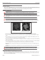
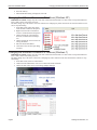
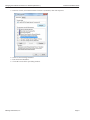
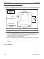
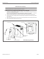
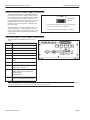
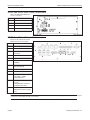
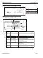
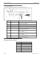
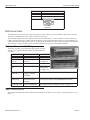
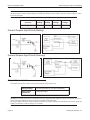
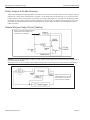
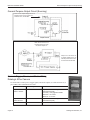
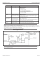
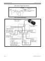
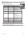
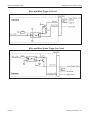
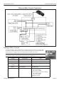
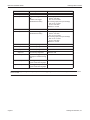
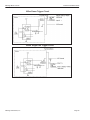
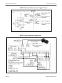
M-Series
QuickStart Guide
Publication Number 843-0151 (Rev J)
Disclaimer
Datalogic Automation Inc. makes no representations or warranties for merchantability or fitness for any particular purpose, regarding Datalogic’s software or hardware. Datalogic Automation Inc. shall not be liable
for errors contained herein or for incidental or consequential damages in connection with the furnishing, performance, or use of this publication or its contents.
Datalogic Automation Inc. reserves the right to revise this publication from time to time and to make
changes in the content hereof without obligation to notify any person of such revision or changes.
Under the copyright laws, neither this publication nor the software may be copied, photocopied, reproduced,
or reduced to any electronic medium or machine-readable form, in whole or in part, without the prior written
consent of Datalogic Automation Inc.
Telephone:
Facsimile:
Web site:
E-Mail:
952-996-9500
952-996-9501
http://www.datalogic.com
[email protected]
Impact, Vision Program Manager, VPM, Control Panel Manager, CPM, Digital Serial Link, Pinpoint Pattern
Find, and DSL are trademarks of Datalogic Automation Inc. Microsoft Windows is a trademark of Microsoft
Corporation. Java is a trademark of Sun Microsystems, Inc. Allen-Bradley and Rockwell Automation are
trademarks of Rockwell Automation.
Datalogic and the Datalogic logo are registered trademarks of Datalogic S.p.A. in many countries, including
the U.S.A. and the E.U.
Copyright © 2002-2013 Datalogic Automation Inc. All Rights Reserved
Technical Support
If you have technical questions about the operation of any Datalogic product, contact your distributor or
Datalogic. Please have the following information available before you call:
• The model and serial number of the device, located on the bottom of the unit. The version number of the
Impact software you are running, found in the title bar of the software.
• The type and version number of the operating system software you are running on the client computer.
M-Series QuickStart Guide
Getting Started
Getting Started
Thank you for using Datalogic M-Series. This guide provides a brief overview to help you get started with your new system. For more detailed instructions, please refer to the Reference Guide (843-0093) and the M-Series Processor and Camera Guide (843-0148). It is important that you note the cautions and warnings in these manuals.
Safety Precautions
Warning: There are no user-serviceable parts inside the Datalogic hardware. To avoid electrical shock, never open
the case. Opening the case or removing the tamper-proof sticker will void the product warranty.
Avertissement: Il n'y a aucune partie utilisateur-utile à l'intérieur du matériel d'Datalogic. Pour éviter le choc électrique, n'ouvrez jamais la valise. L'ouverture de la valise ou l'élimination de l'autocollant inaltérable videra la garantie de produit.
Mounting Warning: Mount the processor with the front or back of the unit facing down. For safety, do NOT
mount the processor with the filter side down. Mounting with the fan side down is acceptable only if approved
metal screen filters have been installed in all fan exhausts.
Metal Screen Filter Installed
Metal Screen Filter NOT Installed.
Do NOT mount fan side down
• Read all of the following instructions before setting up your system. Save this document for later use.
• Follow all warnings and instructions in this manual and in other user guides shipped with your hardware components.
• To avoid damage to the vision system and its components, never plug in or unplug a cable when the power is on.
Always turn off the power supply before you make cable changes.
• Never use the system if a power cable has been damaged. Do not allow anything to rest on a power cable and keep
them away from traffic.
• The air inlets and exhausts on the top and sides of the unit are for ventilation. Do not block or cover these openings
or insert anything into these openings. Metal screen filters may be installed in the fan exhausts.
• Do not expose the vision system to moisture, rain, or snow, and do not use it near water. If a component gets wet
unplug it.
• To avoid injury, never open the case. Opening the case or removing the tamper-proof sticker will void the product
warranty.
Service Personnel Only - Caution: Risk of explosion if battery is replaced by an incorrect type. Dispose of used
batteries according to battery maker’s instructions.
Unpack the M-Series Hardware
When your system arrives, check the shipping cartons for wrinkled or damaged corners, holes through the cardboard, or
other signs of rough handling or abuse. If you find any signs of damage, ask the delivery service to make a note on the
delivery receipt describing the damage.
Page 1
Datalogic Automation, Inc..
Processor Specifications
M-Series QuickStart Guide
Carefully remove the system unit, cameras, cabling, and accessories from the shipping package. Place all equipment you
unpack on a table and inspect each item. Report any damage to the carrier immediately. Save all packing materials so you
can repack the shipment in case you need to move or ship it.
Temperature precautions: If your system arrives in very cold or hot weather, allow all the equipment to reach room temperature before plugging it in. Exposing a cold device to a warm room causes condensation that could damage the system
if power is applied too soon. If condensation forms, wait for it to dry completely.
Processor Specifications
This section lists the general operating specifications for the M-Series Processors.
Processor Operating Environment
Model
MX20** and MX40
MX80
Dimensions
7.8 w x 3.3 h x 6.5 d (in)
200 w x 85 h x 165 d (mm)
9.06 w x 3.23 h x 8.11 d (in)
230 w x 82 h X 206 d (mm)
Weight
4.8 lb. (2.16 kg)
6.61 lb. (3 kg)
Input Power*
10 to 30VDC
, Max. 10A; Min 3.5A
10 to 30VDC
, Min 5A
Temperature
Humidity
0° to +55° C (+32° to +131° F)
0% to 90% (non-condensing)
0° to +55° C (+32° to +131° F)
0% to 90% (non-condensing)
Safety
Compliance
CE/FCC, RoHs, IP30, UL
(MX20 UL Pending)
CE/FCC, RoHs, IP30, UL
Minimum Software Version
MX20 - 10.5.0
MX40 - 10.0.0
10.4.0
*NOTE: The MX20 and MX40 processors require approximately 3.5A @ 24VDC. Datalogic recommends using a 24
VDC power supply capable of providing 3.5A current. The M-Series processors run most efficiently at this voltage which
is commonly used in many manufacturing environments.
The MX80 processor requires approximately 5A @ 24VDC. Datalogic recommends using a 24 VDC power supply capable of providing 5A current. This voltage is commonly used in many manufacturing environments.
**The MX20 processor can accommodate a maximum of two cameras. The maximum image size of each camera is two
Megapixels. (The calculation is: maximum width in pixels * maximum height in pixels < 2,500,000.)
Installing Impact Software
NOTE: The M Device Software is intended for installation only on a Datalogic M-Series processor. You must install it
directly on the processor you intend to use. You cannot install it remotely.
When a new processor is powered on the first time, a monitor, keyboard, and mouse must be connected to the processor to
approve the license agreement.
All the required software was installed on the M-Series processor at the factory. If you want to change the system configuration, you will need to connect an optional monitor, mouse, and keyboard to the processor. For more details, refer to the
M-Series Hardware Guide and Impact Reference Guide. If your system does not work when you are finished with the
setup, review the instructions and diagrams to make sure you made all connections properly.
Resetting the M-Series Processor
To reset the M-Series Processor, press the Reset button on the processor’s front panel. See “MX20 and MX40 Front Panel
Connections” on page 1-8 and “MX80 Front Panel Connections” on page 1-9.
Changing the Camera’s IP Address
1.
2.
3.
4.
5.
Connect to the device with VPM.
Select the Settings tab.
Click the General System Object.
Select the General radio button.
Enter the desired IP address in the IP Address field.
Datalogic Automation, Inc.
Page 2
M-Series QuickStart Guide
Changing the M-Series Processor’s IP Address (Windows XP)
6. Press the Tab key.
7. When the Reboot dialog is displayed, click OK.
Changing the M-Series Processor’s IP Address (Windows XP)
IMPORTANT NOTE: Change only the Local Area Connection named LAN1 or LAN2. These correspond to Ethernet
Ports 1 and 2 on the front of the processor.
DO NOT change any of the other Local Area Connections. Changing any other connection can cause the M-Series cameras to stop functioning.
1. In the Start menu, right click on My
Network Places and select Properties.
2. Right click Local Area Connection
LAN1 or LAN2 and select Properties.
3. On the General tab, select Internet
Protocol (TCP/IP) and click Properties.
4. On the General tab, select Use the following IP address.
5. Enter the desired IP address.
6. Click OK to close all the open dialog
windows.
Changing the M-Series Processor’s IP Address (Windows 7)
IMPORTANT NOTE: Change only the Local Area Connection named LAN1 or LAN2. These correspond to Ethernet
Ports 1 and 2 on the front of the processor.
DO NOT change any of the other connections. Changing any other connection can cause the M-Series cameras to stop
functioning.
1. In the Start menu, click on Control Panel.
2. Under Network and Internet, click on View Network Status and Tasks.
3. On the left side of the screen, click Change Adapter Settings.
4. Right click LAN1 or LAN 2 and select Properties.
Page 3
Datalogic Automation, Inc.
Changing the M-Series Processor’s IP Address (Windows 7)
M-Series QuickStart Guide
5. In the list of items, select Internet Protocol Version 4 (TCP/IPv4), then click Properties.
6. Select Use the following IP address.
7. Enter the desired IP address.
8. Click OK to close all the open dialog windows.
Datalogic Automation, Inc.
Page 4
M-Series QuickStart Guide
Flat Surface Mounting
Flat Surface Mounting
The M-Series Processor may be mounted on any stable surface using the provided case mounting brackets. (Use the
appropriate bracket for the Processor model.) Allow at least 1.5 inches (38.1 mm) of clearance at the sides and top of the
unit.
IMPORTANT: See Mounting Warning on Page 1
Bottom View
Mounting Hole
Dimensions
Processor front
Mounting Brackets (x2)
Provided
Bracket Mounting Screws (x4)
M4, 0.7 mm pitch, 5 mm length Provided
All models
3.2 [80.0]
UNITS: inch [mm.]
Flat Surface Mounting
(Front Up)
MX20; MX40=8.7 [221]
MX80 =9.92 [252]
Mounting Bracket Installation
NOTE: If the Processor uses a Compact Flash card, mount with the Processor front facing upward so the CF
card does not fall out due to vibration.
To mount the Processor using the mounting brackets:
1.
2.
3.
4.
5.
6.
Fasten the two mounting brackets to the bottom of the Processor using the bracket mounting screws.
Using the mounting brackets as a template, mark the surface mounting holes in the desired location. The surface must be sufficiently sturdy to hold the unit, stable, and free of vibration.
Drill four surface mounting holes in the mounting surface.
Insert four mounting screws in the mounting holes and tighten them until approximately 0.2 inches (5 mm) is
left exposed. The mounting screws must be at least size #12 (min. 0.216 inches or 5.486 mm) and long
enough to provide sufficient support.
Maneuver the Processor so mounting bracket slots align with the mounting screws.
Place the slots over the screws and slide the Processor down until the screws fit snugly into the mounting
bracket slots.
DIN Rail Mounting
The M-Series Processor may be bottom-mounted on a DIN rail using the optional DIN Rail Mount kit (MX20/MX40: Part
# 606-0683; MX80: Part # 95A906038).
Page 5
Datalogic Automation, Inc.
DIN Rail Mounting
M-Series QuickStart Guide
DIN Rail Mount Kit Installation
NOTE: If the Processor uses a Compact Flash card, horizontal mounting is recommended (the Processor
front facing upward) so the card does not fall out due to vibration.
To mount the Processor using the DIN Rail Mount kit (see diagram):
1.
2.
3.
4.
5.
To fasten the mounting bracket to the bracket holding plate, insert the bracket mounting screws from the
reverse side of the bracket holding plate.
Be sure to use the appropriate holes in the holding plate for the desired bracket orientation —horizontal or
vertical. The part of the bracket that contains the butterfly clip should be on the bottom.
Fasten the bracket holding plate onto the bottom of the processor using the plate mounting screws.
Hook the bottom of the mounting bracket in the bottom flange of the DIN rail. The butterfly clips will offer
some resistance.
While exerting slight upward force, clip the top of the mounting bracket over the top flange of the DIN rail.
Verify that the bracket is clipped securely to the rail.
IMPORTANT: See Mounting Warning on Page 1
Processor front
Processor front
Butterfly
Clip
Plate
Mounting
Screws
(x4)
Bottom View
Bracket Mounting
Screws (x2)
Mounting Bracket
Datalogic Automation, Inc.
Bracket Holding Plate
DIN Rail Mounting (Fan Down)
Page 6
M-Series QuickStart Guide
MX20 and MX40 Processor Power Supply Connection
IMPORTANT: See Mounting Warning on Page 1
Processor front
Butterfly
Clip
Bottom View
Bracket Mounting
Screws (x2)
Plate
Mounting
Screws
(x4)
Mounting Bracket
DIN Rail Mounting (Front Up)
Bracket Holding Plate
Warning: To avoid electrical shock, disconnect all power to the power supply before working on it.
Avertissement: Pour éviter le choc électrique, débranchez toute la puissance à l'alimentation d'énergie avant de travailler à lui.
MX20 and MX40 Processor Power Supply Connection
The MX20 and MX40 power inputs use standard
spade terminals to connect the power supply. The
ground terminal on the power input must be connected to the power supply’s grounded chassis/
enclosure. This connection is needed to insure
electromagnetic compliance and proper operation.
The MX20 and MX40 processors require approximately 10A @ 10VDC; 3.5A @ 24VDC; and 3A
@ 30VDC. Datalogic recommends using a 24
VDC power supply capable of providing 3.5A
current. The M-Series processor runs most efficiently at this voltage which is commonly used in
many manufacturing environments.
Page 7
Power Connector
1
3
2
1
Connect Ground terminal to Power Supply Circuit Ground
2
Connect - terminal to Power Supply Minus
3
Connect + terminal to Power Supply 10 to 30VDC*
Datalogic Automation, Inc.
MX80 Processor Power Supply Connection
M-Series QuickStart Guide
MX80 Processor Power Supply Connection
The MX80 power input uses a Datalogic-supplied
connector. Wire the power supply cable to the connector, then plug it into the power connector on the
rear of the processor. The ground terminal on the
power input must be connected to the power supply’s
grounded chassis/enclosure. This connection is
needed to insure electromagnetic compliance and
proper operation.
Power Connector
The MX80 processor requires approximately 5A @
24VDC. Datalogic recommends using a 24 VDC
power supply capable of providing 5A current. This
voltage is commonly used in many manufacturing
environments.
V+
GND
VPOWER INPUT
10-30VDC
Connect GND terminal to Power Supply Circuit Ground
Connect V- terminal to Power Supply Minus
Connect V+ terminal to Power Supply 10 to 30VDC*
MX20 and MX40 Front Panel Connections
This is the MX20 and MX40 Processor’s front
panel.
Symbol
J
Function
A
Status Lights (see Page 10)
B
Reset Button (Resets the processor)
C
Keyboard and Mouse
D
USB Ports 2.0 (2)
E
LAN Ethernet Ports (2)
F
Compact Flash Socket (See Note
below)
G
VGA Connector
H
Serial Port 1 - See “MX20 and MX40
Serial Cable” on page 1-11
I
M-Series Camera Connectors (CAM1CAM4) MX20 has only 2 POE ports
(CAM1-CAM2)
Cable 606-0457-x
J
Digital I/O Connector - Cable 6060675-xx with terminal block 661-0403
A
I
D
E
H
G
F
C
B A
Note: If a Compact Flash card is present in the socket, it can be used for extended storage by the MX20 and MX40 processors. Do NOT insert or remove the card while the unit is powered on.
Datalogic Automation, Inc.
Page 8
M-Series QuickStart Guide
MX20 and MX40 Rear Panel Connections
MX20 and MX40 Rear Panel Connections
This is the MX20 and MX40 Processors’ rear panel.
Symbol
Function
A
USB Port
B
Serial Port 2
C
Speaker and Microphone
D
Power Switch
A
B
D
C
MX80 Front Panel Connections
These are the connections for the
MX80 Processor’s front panel.
Symbol
J
Function
A
Status Lights (see Page 11)
B
Power Button
C
Reset Button (Resets the
processor)
D
Keyboard and Mouse
E
Gigabit Ethernet Ports (2)
F
DVI-I Video Connector (VGA
Capable)
G
CFast Compact Flash Socket
(See Note below)
H
USB 3.0 Ports (2)
I
USB 2.0 Ports (4)
J
M-Series Camera Connectors (CAM1 - CAM4)
Cable 606-0457-x
K
Front Digital I/O Connector (I/
O 1-16)
Cable 606-0675-xx with terminal block 661-0403
L
Serial Port 1 (Com 5) See
“MX80 Serial Cable” on page
1-12
K
L
I
H
G
F
E
D
C B A
Note: If a Compact Flash card is present in the socket, it can be used for extended storage by the processor. Do NOT insert
or remove the card while the unit is powered on.
Page 9
Datalogic Automation, Inc.
MX80 Rear Panel Connections
M-Series QuickStart Guide
MX80 Rear Panel Connections
MX80 Processor’s rear panel connections
Symbol
A
B
C
Function
A
Do Not Use. (For future
expansion)
B
Serial Ports 2-4 (COM 2-4)
C
Speaker and Microphone
MX20 and MX40 Status Lights
These are the status lights on the front of the MX20 and MX40 Processors.
E
D
A
B
C
F
G
Symbol
Name
When lit indicates:
A
PoE: MX40 = 4
MX20 = 2
Power over Ethernet (PoE) is active (M1xx camera
only)
B
Power
Power is On
C
HDD
Blinking: Solid-state hard drive is active
D
PoE Activity/Link:
MX40 = 4; MX20 = 2
On: Link is established
Blinking: Data is being transferred
E
PoE Speed:
MX40 = 4; MX20 = 2
Off: 10 Mbps
Green: 100 Mbps
Orange: 1000 Mbps (Gigabit)
F
LAN 1 and 2 Speed
Off: 10 Mbps
Green: 100 Mbps
Orange: 1000 Mbps (Gigabit)
G
LAN 1 and 2 Activity/Link
On: Link is established
Blinking: Data is being transferred
Datalogic Automation, Inc.
Page 10
M-Series QuickStart Guide
MX80 Status Lights
MX80 Status Lights
This illustration shows the status lights on the front of the MX80 Processor.
E
F
D
A
B
C
G
H
Symbol
Name
When lit indicates:
A
Diagnostic
Continuously: No physical storage connected
Blinking: No memory installed
B
HDD
Blinking: Solid-state hard drive is active
C
Power
Power is On
D
PoE (4)
Power over Ethernet (PoE) is active (M1xx camera only)
E
PoE Activity/Link (4)
On: Link is established
Blinking: Data is being transferred
F
PoE Speed (4)
Off: 10 Mbps
Green: 100 Mbps
Orange: 1000 Mbps (Gigabit)
G
LAN 1 and 2 Speed
Off: 10 Mbps
Green: 100 Mbps
Orange: 1000 Mbps (Gigabit)
H
LAN 1 and 2 Activity/Link
On: Link is established
Blinking: Data is being transferred
M-Series Processor Serial Outputs
MX20 and MX40 Serial Cable
Pin Number
Page 11
Signal Name
1
Carrier Detect (CD)
2
Received Data (RxD)
3
Transmitted Data (TxD)
4
Data Terminal Ready (DTR)
5
Signal Ground (GND)
6
Data Set Ready (DSR)
7
Request To Send (RTS)
Datalogic Automation, Inc.
MX80 Serial Cable
M-Series QuickStart Guide
Pin Number
Signal Name
8
Clear To Send (CTS)
9
Ring Indicator (RI)
Pin 1
9 Pin Male
(Pin Side)
MX80 Serial Cable
The MX80 processor provides four serial port connections. The connector on the front panel is Serial Port 1 (COM 5)
which uses a standard serial cable. CAM 1 controls this serial port.
The rear panel connector has three serial port connections for Serial Ports 2, 3, and 4 (COM 2, 3, and 4 respectively).
CAM 2 controls Serial Port 2, CAM 3 controls Serial Port 3, and CAM 4 controls Serial Port 4. Use the Datalogic provided cable which has a DB-62P connector on one end and three standard serial port connectors (DB9) on the other end.
The connector wiring pin numbers on the three DB9 connectors are the same as the MX20 and MX40.
M-Series Processor I/O Wiring
To connect Processor power and input/output signals, use cable
606-0675-xx (37 pin D-sub Male to Male) with terminal block
661-0403.
Terminal Name
Signal
Notes
Input Cmn (2)
Input Common
Input 1 through
Input 16
Input 1+ through
Input 16+
Output Ground (2)
Output Ground
Output +5 to +35
VCC
Output Control Voltage
See Supply
Voltage table
on page 1-13
Output 1 through
Output 16
Outputs 1 through 16
(sinking or sourcing
selectable)
See “Pullup Jumpers to Enable Sourcing” on page 1-14
Outputs Sourcing
Pullups VCC
Output Pullup - use if
Output needs to be
sourcing
+24 VDC
(Jumpers JP1 through JP16 enable/disable connection)
JP1 through JP16
Pullup Enable/Disable
See “Pullup Jumpers to Enable Sourcing” on page 1-14
See Input table
on page 1-13
Input Characteristics
The diagrams and table below describe the input characteristics and how to wire a sensor to a general purpose or event
input.
Datalogic Automation, Inc.
Page 12
M-Series QuickStart Guide
General Purpose Input Circuit (Sinking)
Note: All connections to inputs must be made using properly grounded shielded cable.
All inputs must be wired as either sinking or sourcing, they cannot be mixed. There is only one “Input Common” connection for all the inputs.
Input Resistance
(nominal)
Input
Voltage
Turn On
Voltage
Turn Off
Voltage
Isolated
Voltage
1.2k @ 0.5 W
0-24 Vdc
>3 Vdc
< 0.8 Vdc
2500 Vrms
General Purpose Input Circuit (Sinking)
General Purpose Input Circuit (Sourcing)
Output Characteristics
The M-Series Processors contain sixteen general-purpose output connections.
Supply Voltage
+5 VDC (minimum) to +35 VDC (maximum)
Sink Current
(maximum)
1 Amp per output
NOTES: An external power source is required to power an output load. The outputs are merely switches that are open or
closed. All output connections must use properly grounded and shielded cable.
The Trigger Signal and Strobe Output for M-Series cameras are separate and not part of the M-Series Processor inputs and
outputs. See M-Series Cameras on page 3-1 for details.
Page 13
Datalogic Automation, Inc.
Pullup Jumpers to Enable Sourcing
M-Series QuickStart Guide
Pullup Jumpers to Enable Sourcing
Jumpers JP1 through JP16 enable and disable the connection between their respective Output and the “Outputs Sourcing
Pullups VCC” signal on the terminal block. If a jumper is in the Enable position, the Sourcing VCC is connected to the
Output and it provides a sourcing signal (it is normally low and goes high when On). If a jumper is in the Disable position,
the Output provides a sinking signal (normally high and goes low when On). The Discrete Output tool in the vision program must be programmed to provide the desired output level. Refer to Discrete Output tool in the Impact Reference
Guide (843-0093).
General Purpose Output Circuit (Sinking)
This is not an output voltage source. An
external power source must be connected to VCC, as indicated.
NOTES: To prevent output damage, all inductive loads must have noise suppressors connected directly across the load, as
close to the load as possible.
The Output +5 to +35 VCC terminal is not an output voltage source. An external power source must be connected to it.
Output +5 to +35 VCC is not an
output voltage source. An external power source must be connected to VDD, as indicated.
Datalogic Automation, Inc.
Page 14
M-Series QuickStart Guide
General Purpose Output Circuit (Sourcing)
General Purpose Output Circuit (Sourcing)
This is not an output voltage source. An
external power source must be connected to VCC, as indicated.
Note: To turn PLC On, turn
M Output Off. To turn PLC
Off, turn M Output On.
Output +5 to +35 VCC is not
an output voltage source. An
external power source must
be connected as indicated.
Camera Trigger, Power, and Strobe Wiring
Datalogic M1xx Camera
To connect M1xx camera power, trigger signals, and strobe outputs, use cable 606-0674-xx (6
pin to DB9) with terminal block 661-0399.
Page 15
Terminal Name
Signal
Notes
Optional Camera
Power +12VDC
Camera Power
Required when NOT using Power
Over Ethernet (PoE)
+12 VDC (+-10%) @ 250 mA Max
Maximum: +13.2 VDC
Minimum: +11.3 VDC
Optional Camera
Power Ground
Camera Power Ground
Required when NOT using Power
Over Ethernet (PoE)
I/O Ground
I/O Ground
Datalogic Automation, Inc.
Datalogic M1xx Camera
Terminal Name
M-Series QuickStart Guide
Signal
Notes
Trigger In**
Camera Trigger In
0 to +24 VDC recommended
Maximum +30 VDC
As sinking input
Off: 0 to +1.4 VDC
On: +2.2 to +24 VDC; 5 to 15 ma
As sourcing input (see Trigger Pullup +VCC)
Off: +2.2 to +24 VDC; 5 to 15 ma
On: 0 to +1.4 VDC
Trigger Pullup
+VCC**
Trigger In Pullup - use if
Trigger In needs sourcing (see Note 1 below)
+24 VDC recommended
Maximum +30 VDC
(**Block contains 1.6k Ohm 1W resistor between Trigger In
and Trigger Pullup +VCC)
Strobe Output
Pullup +VCC*
Strobe Supply Voltage use if Strobe Trigger
Output needs sourcing
(see Note 2 below)
Based on Strobe requirement (optional)
Max: +30 VDC; 50 ma
(*Block contains 1.6k Ohm 1W resistor between Strobe Trigger Output and Strobe Output Pullup +VCC)
Strobe Trigger
Output*
Trigger Out to Strobe
(see Note 3 below)
DO NOT APPLY ANY VOLTAGE DIRECTLY TO THIS OUTPUT. DO NOT WIRE OUTPUTS IN PARALLEL.
NOTE 1: If Camera Trigger In requires a sinking signal, set the Software Trigger Event to Rising Edge. If it requires a
sourcing signal, set the Software Trigger Event to Falling Edge.
NOTE 2: If Strobe Trigger Output requires a sinking signal, set the Strobe Trigger Output to Falling Edge. If it requires a
sourcing signal, set the Strobe Trigger Output to Rising Edge.
NOTE 3: Disconnecting the camera will turn on some strobe lights.
M1xx Trigger In Circuit
WARNING: Never wire M1xx Camera Strobe Outputs in parallel with M1xx, M2xx, or M3xx Camera Strobe Outputs.
This will damage the cameras.
Datalogic Automation, Inc.
Page 16
M-Series QuickStart Guide
Datalogic M1xx Camera
M1xx Strobe Trigger Output Circuit
M1xx Terminal Connections
Page 17
Datalogic Automation, Inc.
Datalogic M2xx and M3xx Camera
M-Series QuickStart Guide
Datalogic M2xx and M3xx Camera
To connect M2xx and M3xx camera power, trigger signals, and strobe outputs, use cable 6060673-xx (12-pin to HD-15) with terminal block 661-0400.
Terminal
Camera Power Ground
I/O Ground
Camera Power +VDC
Signal Name
Notes
Camera Ground
I/O Ground
Camera Power
+12 to +24 VDC recommended
@ 500 mA Max
Maximum: +30 VDC
Power for Strobe Trigger Out
+3.3 to +24 VDC; 50 mA Max
Maximum: +30 VDC
Input 2 Pullup +VCC
DO NOT USE
Not Currently Supported
Trigger Pullup +VCC
Trigger In Pullup - use if Trigger In needs sourcing input
Recommended: +24 VDC
Trigger In
Camera Trigger In (see Note
1 below)
0 to +24 VDC recommended
Maximum +30 VDC
As sinking input
Off: 0 to +1.4 VDC
On: +2.2 to +24 VDC; 5 to 15 ma
As sourcing input (see Trigger Pullup
+VCC)
Off: +2.2 to +24 VDC; 5 to 15 ma
On: 0 to +1.4 VDC
Input 2
DO NOT USE
Not Currently Supported
Strobe Trigger Out
Trigger Out to Strobe (see
Note 2 below)
DO NOT APPLY GROUND DIRECTLY
TO THIS OUTPUT.
Output 2
DO NOT USE
Not Currently Supported
Output 3
DO NOT USE
Not Currently Supported
Output 4
DO NOT USE
Not Currently Supported
Output +VCC
NOTE 1: If Camera Trigger In requires a sinking signal, set the Software Trigger Event to Rising Edge. If it requires a
sourcing signal, set the Software Trigger Event to Falling Edge.
NOTE 2: If Strobe Trigger Output requires a sinking signal, set the Strobe Trigger Output to Falling Edge. If it requires a
sourcing signal, set the Strobe Trigger Output to Rising Edge.
Datalogic Automation, Inc.
Page 18
M-Series QuickStart Guide
Datalogic M2xx and M3xx Camera
M2xx and M3xx Trigger In Circuit
M2xx and M3xx Strobe Trigger Out Circuit
Page 19
Datalogic Automation, Inc.
Datalogic M5xx Camera
M-Series QuickStart Guide
M2xx and M3xx Terminal Connections
Datalogic M5xx Camera
To connect the M5xx, use terminal block 661-0401 with cable 606-0673-xx (12-pin to HD15 camera I/O) and cable 606-0674-xx (6 pin to DB9 camera power). For details about programming the Line Trigger, refer to the Impact Reference Guide (843-0093).
NOTE: Do NOT use the M2xx/M3xx terminal block (661-0400) or M1xx block (661-0399)
to connect this camera. They will NOT provide the correct signal levels.
Terminal
Camera Power Ground
Signal Name
Notes
Camera Ground
See Note 1 Below
I/O Ground
See Note 1 Below
Camera Power
+12VDC
Camera Power
+12 VDC (+-10%) @ 700 mA Max
Input 1 -
No Connection
DO NOT USE
Input 1 +
Frame Start Trigger
As sinking input
Off 0 to +0.8 VDC
On: +2.0 to +5 VDC
As sourcing input (see Input 1 Pullup)
Off: +2.0 to +5 VDC
On 0 to +0.8 VDC
Maximum: +5 VDC
I/O Ground
Datalogic Automation, Inc.
Page 20
M-Series QuickStart Guide
Terminal
Datalogic M5xx Camera
Signal Name
Notes
Input 2 -
No Connection
DO NOT USE
Input 2 +
Single Line Trigger
OR
Phase A Line Trigger
(Quadrature Encoder)
As sinking input
Off 0 to +0.8 VDC
On: +2.0 to +5 VDC
As sourcing input (see Input 2 Pullup)
Off: +2.0 to +5 VDC
On 0 to +0.8 VDC
Maximum: +5 VDC
Input 3 -
No Connection
DO NOT USE
Input 3 +
Phase B Line Trigger
(Quadrature Encoder)
As sinking input
Off 0 to +0.8 VDC
On: +2.0 to +5 VDC
As sourcing input (see Input 3 Pullup)
Off: +2.0 to +5 VDC
On 0 to +0.8 VDC
Maximum: +5 VDC
Output 1 -
Not Currently Supported
DO NOT USE
Output 1 +
Not Currently Supported
DO NOT USE
Output 2 -
Not Currently Supported
DO NOT USE
Output 2 +
Not Currently Supported
DO NOT USE
Input 1 Pullup +5VDC
Frame Start Trigger Pullup use if Input 1 needs sourcing
input
Maximum: +5 VDC
Input 2 Pullup +5VDC
Line Trigger Pullup - use if
Input 2 needs sourcing input
Maximum: +5 VDC
Input 3 Pullup +5VDC
Line Trigger Pullup - use if
Input 3 needs sourcing input
Maximum: +5 VDC
NOTE 1: To help prevent ground loops and possible false triggering, we recommend connecting I/O Ground to Camera
Power Ground.
Page 21
Datalogic Automation, Inc.
Datalogic M5xx Camera
M-Series QuickStart Guide
M5xx Frame Trigger Circuit
M5XX Single Line Trigger Circuit
Datalogic Automation, Inc.
Page 22
M-Series QuickStart Guide
Datalogic M5xx Camera
M5XX Quadrature Encoder Line Trigger Circuit
M5XX Trigger Terminal Connections
Page 23
Datalogic Automation, Inc.
Datalogic M5xx Camera
Datalogic Automation, Inc.
M-Series QuickStart Guide
Page 24