1
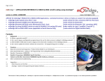
General Tips for Installation of
mObridge into Porsche Vehicles
Disclaimer: the information herein is provided as a convenient “as-is” reference only. The information herein is not guaranteed to be accurate
and is only a collection of “tips” based upon varied installer experiences and knowledge sharing. There is no warranty implied or expressed for
the installer or user of the information herein. As always, there is no substitute for knowledge and experience combined with correct tools and
equipment. Installation of components, particularly aftermarket electronics, is a specialized field and the installer is expected to understand basic
automotive electrical concepts, wiring techniques, and safety or fundamental aspects of fuses, insulating wiring and connections, and proper
mounting of devices so as to eliminate potentially destructive interference with existing vehicle wiring and function. As such, the information
herein implies the usage of proper tools and equipment that an installer reasonably skilled in the field must have to conduct such techniques.
By using this information, the installer or consumer with reasonable expertise, agrees to hold harmless the publisher of this information for any
harm or damages with respect to this information caused while using the informational tips herein as a guide to installation of aftermarket
components into a vehicle.
By using this information, professional installers and retailers or dealers performing installation are assumed to have the appropriate expertise.
They are also assumed to have the certifications and permits necessary to perform such operations in their applicable jurisdictions. The installer
and/or installer’s insurer is also expected to assume liability for any damages due to faulty installation.
page 1 of 14
!
!
1 Never bend fiber optic lines sharply (acutely) or at more than
about 2” radius or permanent damage may result to the fiber.
2 Battery power (+) to the unit must be fused by a value of 5A.
On a 10A circuit or the radio’s circuit is acceptable (safe, OK).
3 Power to mObridge must be constant battery (B+). It cannot
be from a vehicle power plug. Vehicle power plug is not
consistently constant power, despite appearances or first
apparent behavior. Best location to source power is at the
Head Unit’s own power or CD changer’s power wire (e.g., in
Porsche red wire with yellow stripe).
4 If vehicle is intended to be serviced (diagnosed) by the dealer,
bypass switch should be put into the ON mode. It is not plug
and play (vehicle power cycle must be done / complete sleep/
wake cycle in order to properly initialize MOST bus in
mObridge’s bypass / non-bypass mode.
5
Same goes for first installation / or replugging mObridge into
vehicle after disconnection. MOST bus is not hot “plug and
play”. Do not expect system to immediately work after
plugging in units and turning on vehicle. If any MOST piece
has been disconnected, vehicle must go though a complete
deep power cycle to reinitialize the MOST bus properly before
operation will normalize again.
page 2 of 14
A Note About MOST bus Activation in Porsche
mObridge requires the MOST bus be active in the installed vehicle:
MOST is always active in cars with PCM (screen type) head unit. No enabling of
CD Changer is necessary.
MOST is NOT ACTIVE by default in vehicles with just the CDR radio. If the vehicle
has ANY one of the following options, MOST will already be active: CD Changer,
Bose sound, Satellite Radio. If the vehicle has just the CDR and none of these
options, it will require enablement of MOST (enable for CD Changer) by the
Porsche (typically dealership) diagnostic tester.
Tools & Supplies You Should Have On Hand
Set of common Torx screwdrivers
Mini flat-head screwdriver
(some vehicles) Phillips screwdrivers
Rag(s)/towels
(strongly recommended) DC multimeter for verifying voltage
Diagonals (wire snips)
Automotive crimp terminal set and crimper/wire stripper
Electrical tape
page 3 of 14
Porsche Under-dash Installation Notes
(997 shown, Cayman very similar)
(CDR24 shown, steps are same for PCM)
mObridge unit is installed behind the climate
control unit and below the CDR24, accessible via
this panel.
Remove foam
underpanel, if necessary
1. In right passenger footwell, (if cover is
equipped) remove foam cover pad behind the
dashboard. It may not be completely necessary to
remove this piece but may allow for better access.
2. The small carpeted piece that houses the
power plug must be removed. There is one Torx
type screw affixing this piece in place, which can
be found hidden beneath a small hole in the
carpeting. Note that sometimes this screw feels
like it is threading in and out very difficultly, but this
is normal – it is the normal feeling of the fit
between the screw and the clip that it screws into.
Remove
Torx
screw
slide
After unscrewing, slide the small carpeted piece
out as shown. It may make the job easier to
unplug the power plug’s connector to completely
remove the piece.
3. You should now have access to the two Torx
screws that secure the side panel flanking the
center console. Remove these,
Note: Alternate Step-by-Step Instructions
for CDR24 or PCM2 removal in 997 and 987
can be found later in this document.
page 4 of 14
Porsche Under-dash Installation Notes
(997 shown, 987 very similar)
CLIP
This piece in 987
CLIP
4. Snap out and slide out toward rear of car.
Note: it may help to have glovebox drawer open
to perform this step.
CLIP
(Notice the three snap clips that hold these side
panels in place. Shown circled in photo below.)
Overcoming the three clips should not require
any additional tools – just snap the panel out,
rearwards. Note that the top clip can be a bit
difficult, usually requiring a bit more
aggressive cocking and pull of the panel to
overcome it.
Note: Alternate Step-by-Step Instructions
for CDR24 or PCM2 removal in 997 and 987
can be found later in this document.
Glovebox
With access panels removed, mObridge visible. SD
card slot for updates is on bottom side in this depiction
(toward floor of car).
The card springs and clicks into the slot, so as to be
protruding only about 1mm. From the surface of the
case. To remove, depress the card and it will likewise
click and spring out.
Card slot this side
page 5 of 14
Step-by-Step Instructions for PCM2 and CDR24 Removal in 997 and 987
Step 1 - Remove small carpeted trim piece from side of center console by PCM (Beside PCM)
Using Torx wrench size T-30
Step 2 - Remove two leather side trim pieces using Torx wrench size T-20
Step 3 - Using 5mm Allen wrench turn four (two each side) black hex locks 1/4 - 1/2 turn to
unlatch side locks. Do not force these. They turn very easily in the correct direction. Open
glove box on passenger side to access these latches.
Step 4 – There is a 7mm hex head screw on the passenger (RHS) side that you need to back
out to carefully slide out PCM.
Step 5 – Gently slide the PCM out to reveal the rear MOST fiber-optic connector and the ISO
radio I/O connector (pinout also available in this manual)
Head Unit Removal in Cayenne
Step 1 – Gently pry on the trim surround (A) to remove it from its clips and expose the (Torx)
screws that retain the radio.
Step 2 – Remove the Torx screws retaining the PCM.
Step 3 – Gently slide the PCM out to reveal the rear MOST fiber-optic connector and the ISO
radio I/O connector (pinout also available in this manual)
A. Head Unit Trim
Surround in
Cayenne, screws
hidden beneath.
page 6 of 14
Porsche (CDR24) Under-dash Installation Notes
(997 and 987 Vehicles with BOSE sound)
Fig. A. Bose Sound. Removal of Subwoofer for Access
by Removing Grill for Access to Hidden Screw.
In the passenger footwell against the center console
some vehicles have the Bose subwoofer assembly. This
assembly blocks access to the center console to an area
where installer may wish to route wiring or fiber-optic.
To temporarily remove this piece for access the plastic
grill piece above snaps out.
Behind that is hidden a Torx-head bolt holding the
assembly in place.
page 7 of 14
Connector Pin-Out of Porsche Head Units with MOST
(every Porsche sound system starting model year 2003)
Actual PCM
MOST
“2+0” plug
4
8
4
(30 +)
(B+)
[Red/Green]
Light out
(to CDC or
mObridge)
8
(30-)
(Ground)
[Brown]
Light in from rest of
car (amplifier [if Bose]
or CDC or mObridge)
(B+) [Red/Green]
(Ground) [Brown]
If installing in the vehicle cabin, such as under dash or in glove
compartment, this is the best location to source power and ground for
mObridge. It’s “clean” power, fused, and guaranteed constant.
page 8 of 14
Installation in Cayman (997 and 987 similar) in CDC Location
Of course, the plastics covering these areas must first come off, using simple screwdriver(s).
Fig. A. Depicting Location of Unit in a Cayman where CDC would normally go.
Fig. B. Look Closely Behind Brake Booster and You Will See the Optical
that is Meant to Go To CDC. If the vehicle has CDC of course CDC is
connected here. If the vehicle has Bose and/or Satellite Radio but no
CDC, the MOST ring will be active and there will be a BYPASS LOOP
connected here to complete the MOST ring.
Plastic
bracket
holding connector
(and bypass loop
when applicable)
can be unsnapped
here with needlenose pliers to get
sufficient access,
page 9 of 14
Installation in Cayman (997 and 987 similar) in CDC Location
Alternative to using the CDC Optical connection is to tap inline at the amplifier
(Bose sound vehicles)
Fig. B. Amplifer
Fig. A. Conceptual overview of this configuration
t
PCM or CDR
lig
h
In terms of cars that DO NOT have a CDC
(mObridge is a stand-in for the CDC):
The fiber, coming from the PCM/CDR
fiber on the right side of the amplifier’s
MOST connector (looking from back of
connector standpoint), is removed
from the amplifier MOST connector.
Then it is routed into the right side of
mObridge’s MOST connector (insert
directly or use a coupler)
And the fiber on the left side of
mObridge’s MOST connector routed to
the right side of the amplifer’s MOST
connector (the previously vacated
position)
iPod
Unit
AMP
This order of components in the MOST ring is
also typical for any Porsche model, excepting
Nav and Satellite radio which can be found in
other
diagrams.
THE
ORDER
OF
COMPONENTS IN THE RING IS IMPORTANT
AND CANNOT BE CHANGED AROUND.
AMPLIFIER
MOST connector is down here
(obscured, difficult to see when
standing looking at amplifier). It is a
2+0 style with the latch on the side,
easy to feel around and remove.
page 10 of 14
Installation in the Front Passenger Footwell Area of Porsche Cayenne
Fig. A. Porsche Cayenne Front Installation
Find screws behind the metal trim strip
here holding the glovebox, within the
rubber bumpers inside the glovebox,
as well as at least one screw on the
underside of the glovebox.
As you can see, removal of the glovebox is
required. To do this, the metal trim strip
above the glovebox snaps out to reveal
screws. As well, there are screws affixing it
along the bottom of the glovebox in the
footwell, as well as two inside the glovebox
(the rubber bumpers).
A good location for mObridge is behind the
glovebox, JUST ABOVE the plastic footwell
HVAC duct (simply snaps out).
Locating mObridge in this manner, with connections off the back of the CDR/PCM, makes
best use of the parts in the kit and in the view of most experienced installers, the easiest
location to install, particularly if the vehicle has CDC (if the vehicle does not have a CDC
then right rear can be a quick or temporary install).
The iPod cable can be routed to the center console per the dotted green line for
convenient location of the iPod as an alternative to keeping the iPod in the glovebox.
page 11 of 14
Installation in the CD Changer (CDC) Area of Porsche Cayenne
There is sufficient space in the right rear area of Cayenne behind the wheelhouse where the
(optional) factory CDC is located.
Because the cabling run would be difficult and a lot of trim disassembly to run the cables for iPod up
front (such case it’s better to install up front under dash).
This CDC area may be good for a temporary installation or the case where user does not care to
access the iPod directly.
Fig. A. Cayenne Rear at CDC
Fig. B. One Such Cayenne Rear Installation
Note: reports from installers say …
If the car does not already have CDC (as seen Fig. B), the connector is in plain view and it is a
simple operation.
If the vehicle is already equipped with CDC (as seen Fig. A), it is nearly impossible to reach &
disconnect the connectors without removing most of the right rear trim pieces, most likely 1-2 labor
hours. It is necessary to do this either to install an aftermarket piece in this location -OR- simply to
disconnect the CDC and install a bypass loop in its place (that latter which is necessary).
page 12 of 14
Sourcing Power at Porsche CDC Connector
When installing in the CDC area of Porsche Cayenne, the CDC’s connector
can be a good source of the required constant B+ (also referred to as various
things per the European standard: “terminal 30”, “30 power”, or “KL.30”/
”Klemme 30")
The only two wires you are concerned with are Power (B+) [Red/Yel]
and Ground (always Brown in Porsche and other European vehicles)
Red/Yel
(B+ constant)
IF THERE IS NOT POWER
(check with multimeter to be
sure) ON THE RED/YEL
WIRE, CHECK FOR BLOWN
FUSE F9 IN THE CAYENNE’S
RIGHT SIDE FUSE BOX.
Brown
(Ground)
You can tap these two for
constant (and properly fused!)
power to the aftermarket unit.
CDC
page 13 of 14
mObridge SD Card for Firmware Updating
Fully-inserted SD card for
software update.
Notice about 1mm protruding,
fully-inserted position.
mObridge Firmware Update from the SD/MMC memory card.
1. Insert the card at any time with the *.fif file in the root of the SD/MMC card.
2. Firmware will update automatically when vehicle (and mObridge) are on.
3. Typically the total software update process takes no longer than 30 sec. but good to leave
the SD card in there longer. DO NOT SHUT OFF THE VEHICLE FOR AT LEAST 10 MIN. If
the vehicle shuts down, as does mObridge, the current software image will be corrupted, and
mObridge will default back to a factory default image, which may not be the latest software.
It’s also a good idea to leave the SD card in across multiple cycles of normal power up / power
down of the vehicle, to ensure that the new software has gotten on there.
You can then remove the SD card.
4. In PCM vehicles (with screen) you can verify the mObridge firmware version under Disc 6.
page 14 of 14