1
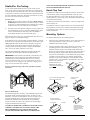
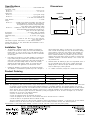
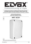
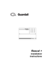
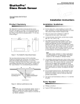
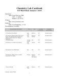
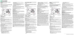
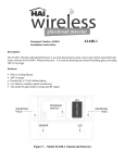
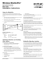
Wireless ShatterPro® Advanced Acoustic Sensor With Pattern Recognition TechnologyTM Model 5845 Installation Instructions Using the ShatterPro ShatterPro sensors are omni-directional, providing 360° coverage. Coverage is measured from the sensor to the point on the glass farthest from the sensor. The sensor can be mounted as close as 3.3' (1m) from the glass. small bathrooms other small acoustically live rooms For glass break protection in such applications, use Sentrol shock sensors on the windows or window frames. 1. Mounted on opposite wall or adjoining walls, range is 20' (6m) for plate, tempered, laminated and wired glass. 2. Mounted on the ceiling, maximum range is 20' (6m) for plate, tempered, laminated and wired glass. Do Not Install In Humid Rooms The Wireless ShatterPro is not hermetically sealed. Excess moisture on the circuit board can eventually cause a short and a false alarm. 3. For armor-coated glass, mount sensor no more than 12' (3.65m) from glass. 2 m 0' (6 ) ) 20' (6 m Recommended Glass Size Minimum 1' x 2' (0.3m x 0.6m) or larger Glass thickness: Plate: 3/32" to 1/4" (2.4mm to 6.4mm) Tempered: 1/8" to 1/4" (3.2mm to 6.4mm) Wired: 1/4" (6.4mm) Laminated: 1/8" to 1/4" (3.2mm to 6.4mm) Optimizing Detection and Avoiding False Alarms For Best Detection, Avoid Installing In Rooms with lined, insulating, or sound deadening drapes Rooms with closed wooden window shutters inside Corners of a room For Best False Alarm Immunity Avoid 24-hour loop applications (perimeter loop OK). Dont use where white noise, such as air compressor noise, is present. (A blast of compressed air may cause a false alarm.) Avoid rooms smaller that 10" x 10" (3m x 3m) and rooms with multiple noise sources such as small kitchens, glass booths noisy areas, garages, small bathrooms, etc. Areas to Avoid glass airlocks and glass vestibule areas noisy kitchens residential car garages small utility rooms stairwells Wireless ShatterPro Avoid 24-Hour Loop Applications Avoid adding (learning) the sensor into 24-hour sensor groups, where the sensor will be armed even when the room is in use. Adding the ShatterPro to a perimeter sensor group, which is armed only when the perimeter doors and windows are armed, will help prevent false alarms. Install the ShatterPro on a perimeter loop which is armed whenever the door and window contacts are armed. Protecting Occupied Areas The ShatterPro false alarm immunity is best in rooms with only moderate noise. For 24-hour occupied area protection, use Sentrol shock sensors or the Sentrol 5885 ShatterPro Plus. Proper Testing The ShatterPro is designed to detect the breaking of framed glass mounted in an outside wall. Testing the sensor with unframed glass, broken bottles, etc., may not trip the sensor. The ShatterPro typically does not trip to glass breaking in the middle of the room no burglar breaks glass in the middle of a room, so such breaks are false alarms. NOTE: ShatterPro may not consistently detect cracks in glass, or bullets which break through the glass. Glassbreak sensors should always be backed up by interior protection. ShatterPro Mounting Location For best false alarm immunity the sensor should be located at least 4' (1.2 m) away from noise sources (televisions, speakers, sinks, doors, etc.). The sensor must always be in direct line of sight of all windows to be protected. It cannot consistently detect glass breaking around corners, in other rooms, etc. There is no front or back, up or down, orientation of the sensor required. Wall Mounting Since the sound of breaking glass travels directionally out from the broken window, the best location for mounting the sensor is on the opposite wallassuming the glass to be protected is within the sensors range and line of sight. The ceiling and adjoining (side) walls are also good sensor locations. Ceiling Mounting Mount the sensor in any type of ceiling in a location which is in direct line of sight of the windows to be protected. However, since sound travels directionally out from the broken window, a position 6 - 10' (2-3m) into the room provides better detection. 1 ShatterPro Pre-Testing Use the Sentrol 5709C hand-held tester to set the sensor into test mode. Set the tester to tempered glass, hold the tester speaker directly on top of the sensor and activate the tester. The sensor will alarm, then it will go into test mode for one minute. When in test mode the LED on the sensor will blink continuously. Extend the test mode time by firing the tester at the sensor at least once a minute. Test the Sensor 1. Holding the tester near the surface of the glass, aim the tester at the ShatterPro and hold down the test button. If drapes or blinds are present, test with the hand-held tester behind the closed drapes or blinds (do not use sensor with heavy or lined drapes). 2. The 5709C tester has a different setting for each type of glass. The tester should always be set for tempered or laminated glass (either is correct and both have the same range) unless the installer is certain that all the glass to be protected is plate glass. When the LED on the sensor goes solid momentarily while the tester is triggered, the glass is within detection range. If the LED does not go solid, but simply continues blinking, re-position the sensor closer to the protected windows and retest. This may require adding additional sensors in order to achieve adequate coverage. It is very rare that the sensor will not activate within its stated range of coverage. Double check adequate battery strength in the hand-held tester. A new tester battery will likely restore range. The sensor will automatically change from test mode to normal mode approximately one minute after it last hears the hand-held tester. IMPORTANT ! Room acoustics can artificially extend the range of a glassbreak sensor. The specified range of the ShatterPro has been established for worst-case conditions. While the sensor will likely function at additional range, it may miss a minimum output break, or room acoustics may be changed at some future time, bringing sensor range back into normal 20' (6m) conditions. Do not exceed the rated range of the sensor, regardless of what the tester shows. NOTE: EACH TIME THE SENSOR ALARMS IT ALSO GOES INTO TEST MODE FOR ONE MINUTE. Hand Clap Test The ShatterPro® 5845 can be checked by the installer or end user while in normal mode, simply by clapping hands loudly under the sensor. The LED will blink twice, but the sensor will not trip. This verifies visually that there is power to the sensor, and that the microphone and circuit board are functioning. The hand clap activation is only momentary, so there is no appreciable effect on battery life. To disable this custom test function, remove the circuit board from the housing and clip one of the wires on the LED. The LED will no longer be operational, but the sensor can still be tested using the transmitter and the control panel. Mounting Options The Wireless ShatterPro has two mounting options: 1. Place the wireless transmitter inside the sensors base housing. For some large transmitters, it will be necessary to remove the transmitter board from its housing. 2. For large transmitters which will not fit into the sensor base, or for a smaller appearance with a standard size transmitter, use the transmitter bracket with the sensor module (5845 models only). Remove the sensor module by depressing the catch in the center of the housing. Snap the sensor module onto the bracket and route the wires into the transmitter. Use the double-stick tape provided to hold the wire in the brackets wire channel, and to hold the transmitter to the bracket. Mount the sensor/transmitter bracket assembly. (Note: If the transmitters mounting holes dont fit the brackets hole pattern, the Sensor Transmitter bracket will have to be Module mounted to the wall or ceiling before attaching the transmitter.) Lid Base To moduledepress depterss latch, Toremove remove sensor sensor module, latch, rock upoff offthe theposts posts. rockthe themodule module up How Test Mode Works The Pattern Recognition Technology of the ShatterPro ignores most false alarm sounds, including glassbreak testers. In order to test the ShatterPro, a test mode is used. With the sensor in test mode, processing of the glassbreak pattern in the upper and lower frequencies is disabled. The ShatterPro is then listening only for the mid-range frequencies, which the 5709C tester reproduces. Its the mid-range frequencies that determine sensor range. IN NORMAL MODE THE LED DOES NOT BLINK UNLESS IT HEARS A LOUD SOUND. IN NORMAL MODE, THE SHATTERPRO WILL NOT TRIP TO THE TESTER, UNLESS THE TESTER IS HELD NEXT TO THE SENSOR. 2 Snap sensor module onto bracket. Mounting Tape Run wires to transmitter and attach transmitter to base. Sensor module Transmitter Bracket Use the pre-punched double-sided mounting tape to hold the wires in the channel and to secure the transmitter. Wireless ShatterPro Wiring the ShatterPro 3-Volt Model 584503-W (shares transmitter battery) 9-Volt 584509-W (shares transmitter battery) Red to battery + Red to battery + Black to battery - Black to battery - White normally open (closes on alarm to battery -) White normally high Green normally closed (to battery -) Green normally low Black Black Red Red White Green White Green 584503-W ITI 3.5V Programmable 584503-W ITI 3.5V Learn Mode Black Red 584503-W System VI Transmitter Black Red 3.5 V Green (NL) Red 3.5 V Green (NL) 3.5 V 1. Program the learn mode transmitter into the MCU. 2. Connect the ShatterPro to the transmitter as shown. 3. Solder the red lead to the positive battery terminal on the underside of the circuit board. 4. Put the cover on the transmitter and put it back into the back box, snap the ShatterPro cover in place. 5. Test with Sentrol 5709C Shatterbox Tester as directed. Green Black 584503-W Ademco #5816 584509-W Ademco #5716 9V Remove battery. Set SW3 #6 down. Set SW4 #1 up. Do not use magnet. Connect loop wires (green). Connect 9-volt battery terminals. Install battery, observing polarity. Red 3V Black Black Red Green (NL) Green (NL) 584509-W* Honeywell Model 10-6506 (T-8803) 584509-W* AT&T Splice white wire from 584509-W to Green wire from AT&T. Connect Black wire from 584509-W to Battery -. Connect Red wire from 584509-W to Battery +. 12 position Dip Switch. #6 to OFF for CL. #7 to ON for PIR or Glassbreak. Black Red Wireless ShatterPro Green (NL) GND White (NH) Red Black *If using this transmitter inside the back box, the circuit board must be removed from the housing. It can be secured using the double-stick tape provided. For the most secure connections, it is better to solder to the battery connector terminals, instead of using the “buddy-up” clips. 3 Specifications Dimensions Housing material .................................................................. Flame retardant ABS Operational voltage 584503-W .................................................................................. 2.8 to 4.5 V DC 584509-W ....................................................................................... 6 to 16 V DC Current draw 584503-W ......................................................................... 17µA typical average 584509-W ......................................................................... 23µA typical average 5 mA with LED momentarily on Alarm Duration ....................................................................................... 4 seconds Output 584503-W ............... Normally closed output and normally open output with open drain MOSFETs; 700 Ohms max. closed resistance; 10 megOhms min. open resistance; Output voltage must be less than or equal to supplied battery voltage 584509-W ......... Normally low output with NPN transistor and 10M pull up resistor and normally high output with PNP transistor to power +16 V DC max. output voltage RF immunity .................................................... 20 V/meter, 1MHz to 1000MHz Microphone .................................................................. Omni-directional electret Temperature range ................................................. 14° to 120°F (-10° to 50°C) Color .............................................................................................................. White Wiring ............................... 22AWG UL style 1061, CSA T2, color coded wire, passes VW-1 flame test The 584503-W typically works down to 2.1 VDC and the 584509-W typically works down to 3.0 VDC, which allows most transmitters to send a low battery trouble alarm. Side View Front View 4.24" 10.8 cm 1.70" 4.3 cm 3.13" 8.0 cm Installation Tips 1. The ShatterPro is designed to detect the shattering of framed glass mounted in an outside wall. Testing the sensor with unframed glass, broken bottles, etc. may not trip the sensor. The ShatterPro typically does not trip to glass break tests in the middle of a room as such breaks are false alarms. 2. False alarms are most likely to occur when installed on a 24-hour loop in glass airlocks and glass vestibule areas, when mounted above sinks, when used in residential car garages and in other small, acoustically live rooms and rooms where multiple sounds can reflect and eventually duplicate the glass break frequency pattern. For occupied area glass break protection in such applications, use Sentrol shock sensors. 3. Installing the ShatterPro on 24-hour loops will increase false alarms. The ShatterPro is recommended for perimeter loops and is designed to function without false alarms in occupied areas. On a 24-hour loop, which is armed all day/all night every day, the false alarm technology will be pushed to its limit since some sounds in some conditions can duplicate the points on the glass break pattern that the ShatterPro detects. Install the ShatterPro on a perimeter loop, which is armed whenever the door and window contacts are armed. For occupied area installations, ShatterPros false alarm immunity is best in rooms with only moderate noise. 4. ShatterPro detects the shattering of glass. Like all glassbreak sensors, it may not consistently detect cracks in glass, or bullets which break through the glass or break out the glass. Glassbreak sensors should always be backed up by interior protection. 5. Use a lithium 9-volt battery if longer life is needed in the 584509-W Product Ordering Description Model Number Color Wireless ShatterPro, 3-volt model w/ optional bracket 584503-W White Wireless ShatterPro, 9-volt model w/ optional bracket 584509-W White Hand-held Tester 5709C-W White NOTE: This equipment has been tested and found to comply with the limits for a Class B digital device, pursuant to Part 15 of the FCC Rules. These limits are designed to provide reasonable protection against harmful interference in a residential installation. This equipment generates, uses and can radiate radio frequency energy and, if not installed and used in accordance with the instructions, may cause harmful interference to radio communications. However, there is no guarantee that interference will not occur in a particular installation. If this equipment does cause harmful interference to radio or television reception, which can be determined by turning the equipment off and on, the user is encouraged to try to correct the interference by one or more of the following measures: Re-orient or relocate the receiving antenna. Increase the separation between the equipment and receiver. Connect the equipment into an outlet on a circuit different from that to which the receiver is connected. Consult the dealer or an experienced radio/TV technician for help. This device complies with Part 15 of the FCC Rules. Operation is subject to the following two conditions: (1) This device may not cause harmful interference, and (2) this device must accept any interference received, including interference that may cause undesired operation. Protected under U.S. and foreign patents including: 3,863,250; 4,745,398; 4,837,558; 5,192,931 and other patents pending. 11089 Rev E 12/00 Wireless ShatterPro