1
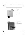
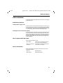
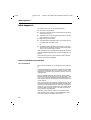
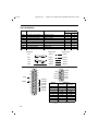
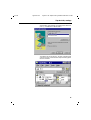
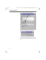
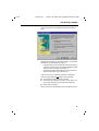
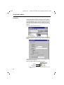
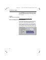
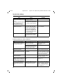
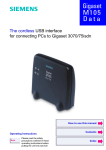
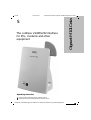
coverm1.fm5
Gigaset M101 Data, eng/deut: A30853-X400-B104-3-74D1
s
The cordless V.24/RS232 interface
for PCs, modems and other
equipment
Operating instruction
Please read the safety precautions outlined in these
operating instructions before putting the unit into service.
ACHTUNG! Schnittkante ggf. auf Titelseite U1 nach außen versetzen wg. Falz-Ausklappseite
Gigaset M101 Data
14.4.99
klapps1.fm5
16.4.99
The most important menus
Starting the program
Registering a Gigaset M101 Data
Setting the operating mode
2
Gigaset V.24 Adapter dt/eng:A30853-X400-B104-3-74D1
klapps1.fm5
16.4.99
Gigaset V.24 Adapter dt/eng:A30853-X400-B104-3-74D1
Overview
Legend
Front
1.
Operating LED,
illuminated when power supply
is active,
see "LEDs and buttons" on page
19
2. Data LED, illuminated during
data transfer operations
3. Reset key
12 3
Back
4. Port for the V.24/RS232
cable
1 = male
2 = female
5. Mains power supply socket for
plug-type AC adapter
4
5
3
giga_m101.IVZ
14.4.99
Gigaset M101 Data, eng/deut: A30853-X400-B104-3-
Contents
Updates and news on the Internet ................................................................................................
Approval and conformity ................................................................................................................
Notes on PC and modem operation ...............................................................................................
Notes on Gigaset Repeater ............................................................................................................
5
6
6
6
Introduction .................................................................................................................................. 7
What is a Gigaset M101 Data? ...................................................................................................... 7
Safety precautions ................................................................................................................... 7
Putting into service ...................................................................................................................... 8
Checking the contents of the package ........................................................................................... 8
Important ........................................................................................................................................ 8
Installing the program package ....................................................................................................... 9
Prerequisites for installation ..................................................................................................... 9
Installation ................................................................................................................................ 9
Check installation is successful ............................................................................................... 9
Connecting stations ..................................................................................................................... 10
Initial configuration ................................................................................................................... 11
Configuration program options ................................................................................................
General .........................................................................................................................................
Starting the configuration program ...............................................................................................
The buttons ..................................................................................................................................
"Connection" tab ...........................................................................................................................
Upper section: connecting to the PC .....................................................................................
Lower section: radio connection ............................................................................................
"Operating mode" tab ...................................................................................................................
Setting the operating mode ...................................................................................................
Special settings for "Direct connection" mode .......................................................................
"Local station" tab .........................................................................................................................
Changing a name ...................................................................................................................
Changing a station type .........................................................................................................
Registering an extension station ............................................................................................
De-registering a extension station .........................................................................................
"Partner station" tab ......................................................................................................................
Changing the name ................................................................................................................
Changing the PIN ...................................................................................................................
12
12
12
12
13
13
13
14
14
15
15
15
15
17
18
18
18
18
LEDs and buttons .......................................................................................................................
Both button functions ..................................................................................................................
Setting a base to logon mode ................................................................................................
Resetting the device to the factory default ............................................................................
LED 1: Gigaset M101 Data status ................................................................................................
LED 2: data transfer .....................................................................................................................
19
19
19
19
19
19
What happens if... ......................................................................................................................
Notes on installation and operation ..............................................................................................
Place of installation ................................................................................................................
Temperature and ambient conditions ....................................................................................
Technical data ..............................................................................................................................
The V.24 interface ........................................................................................................................
Why set a mode? Technical background ...............................................................................
20
20
20
21
21
22
23
4
giga_m101.IVZ
14.4.99
Gigaset M101 Data, eng/deut: A30853-X400-B104-3-74D1
Contents
Tips & tricks, settings ................................................................................................................
Operating from a local station with two remote stations: ............................................................
PC - PC direct cable connection: via RS232/V.24 interface ..........................................................
Setting the direct connection to the correct baud rate ..........................................................
Sharing files ...........................................................................................................................
PC - PC direct cable connection problems: examples .....................................................
MAC and other operating systems ..............................................................................................
Meaning of "local station" and "remote station" ............................................................................
Meaning of "base" and "extension" ...............................................................................................
Meaning of local, remote .............................................................................................................
Support .........................................................................................................................................
Updates and news on the Internet ........................................................................................
Notes on sending faxes directly from the PC ...............................................................................
Configuration management ...................................................................................................
Problems with application programs: ....................................................................................
Hardware problems (PC, modem, ISDN TA.): .......................................................................
Miscellaneous ........................................................................................................................
24
24
25
26
32
33
33
33
33
33
34
34
34
35
35
36
37
Updates and news on the Internet
Visit our site at:
www.siemens.com/pc-communication-support
(always under construction)
5
gigam101.fm5
21.4.99
Gigaset V.24 Adapter dt/eng:A30853-X400-B104-3-74D1
Approval and conformity
Your Siemens Gigaset M101 Data has been certified by the German Federal Office of Telecommunication Approval (BZT). This
equipment has been approved in accordance with the EU directive 91/263/EC Telecommunication Terminals.
This data terminal complies with the requirements of the EU directives:
89/336/EC
EMC Directive
72/23/EC
Low Voltage Directive
and thus carries the CE mark.
Notes on PC and modem operation
When using a modem, software malfunctions in the PC
(e.g. an operating system crash or program errors in the
application software) can prevent the cleardown of a
modem connection from a telephone line. You incur
connection costs for trunk lines that you seize!
Since your Gigaset M101 Data only replaces a serial cable, malfunctions of this kind can also occur here. If such
a problem occurs, check the status of your modem and,
if applicable, reset it.
In the case of one-sided interruption of the mains supply
or complete interruption of your Gigaset M101 Data’s
hop, the interface’s status lines are reset to the initial
status in the partner station within 2 minutes (a modem
then clears down the connection).
Whenever possible, operate the station registered as
user at your PC (lokale Station), since any malfunctions
on the user side can be displayed, for technical reasons,
more quickly than at the base, see "LEDs and buttons"
on page 19.
Should the graphic or sound card be affected by interference from Gigaset M101 Data, rotate Gigaset M101
Data until the interference is removed.
Notes on Gigaset Repeater
The Gigaset Repeater cannot be used to extend the
radio range.
The repeater was designed for use behind Gigaset 2000
base stations.
6
gigam101.fm5
21.4.99
Gigaset V.24 Adapter dt/eng:A30853-X400-B104-3-74D1
Introduction
Introduction
What is a Gigaset M101 Data?
Your Gigaset M101 Data is a cordless V.24/RS232 serial interface consisting of two stations: the lokalen Station and the Partnerstation.
The station connected to the PC is known as the "lokale Station".
The "Partnerstation" is connected to a peripheral device, e.g. a
modem.
Radio link
Local station
Partner station
The connection between the PC and the peripheral device is
routed via the radio link between the lokalen Station and the
Partnerstation.
In addition to both stations, the application features a configuration program.
Of the two stations,
●
one is a "Basis" type station; this is usually the Partnerstation,
●
the other is a "Teilnehmer" type station; this is usually the
lokale Station.
All Gigaset M101 units are "Basis" type stations by default.
When the device is configured for the first time, the Gigaset
M101 Data connected to the PC automatically switches to a
"Teilnehmer" type station. The Teilnehmer station must be registered at the Basis station.
Every Gigaset M101 Data can be operated either as a lokale Station or as a Partnerstation.
Safety precautions
Research has shown that in certain cases, medical
equipment can be affected by activated DECT devices.
A distance of at least one metre should therefore be
maintained between Gigaset M101 Data and the medical equipment. When using cordless telephones in the
vicinity of medical equipment, the regulations of the relevant institution must be observed.
Only use the power supply unit supplied (C39280-Z4C59/C39280-Z4-C168).
7
gigam101.fm5
21.4.99
Gigaset V.24 Adapter dt/eng:A30853-X400-B104-3-74D1
Putting into service
Putting into service
Follow the step-by-step instructions described below for putting
the equipment into service:
1.
Check the contents of the package
2. Install the configuration program
3. Connect the station
4. Conclude commissioning by performing an initial configuration, see "Initial configuration" on page 11.
Checking the contents of the package
The package contains:
M101
Data
Twin
Pack
Gigaset M101 Data
1
2
Plug-type AC adapter C39280-Z4-C59/
C39280-Z4-C168 for mains connection
1
2
Serial 9-pin connection cable for connecting
the V.24/RS232 interface
1
2
CD-ROM with the installation program
1
1
Operating instructions
1
1
Important
Before you put the Gigaset M101 Data into service, the
peripheral device that you want to operate as a cordless
unit (modem, PABX) must be configured at the COM
port on the PC side since it is to be used for transferring
data. For information on configuration, see the appropriate documentation on the peripheral device and your
computer’s operating system. This configuration is particularly necessary for plug&play installations, as otherwise errors can occur depending on the installation routine of the connected peripheral unit.
If you want to operate a modem, for example, via the radio link, first connect the modem directly to the PC, configure it, set up a test connection, and then install the radio link. To do this, disconnect the modem from the PC,
connect the Gigaset M101 Data and perform the configuration.
When choosing a location for the devices, read the
"Notes on installation and operation" on page 20.
8
gigam101.fm5
21.4.99
Gigaset V.24 Adapter dt/eng:A30853-X400-B104-3-74D1
Putting into service
Installing the program package
Prerequisites for installation
For installation, you need:
●
an IBM-compatible PC with the following configuration:
–
Win 95, Win 98 or Win NT operating system
–
2 MB free hard disk memory
–
1 free V.24/RS232 serial interface as
COM port
●
the diskette/CD-ROM containing the installation program
●
Start up the PC and close down any programs active after
start-up.
●
Disconnect any Gigaset M101 Data units from the power
supply and the PC.
●
Insert the data carrier supplied in the drive.
●
Under Start, select Settings, then Control Panel. Doubleclick the Software icon.
●
Select Install. The installation program starts. During installation, the message "No Gigaset M101 Data connected".
Confirm this message with "OK".
●
Terminate the configuration program with "OK"; this concludes the installation operation.
Installation
Check installation is successful
The following errors can occur during installation:
Problem
Result
Insufficient memory
Error message, please try freeing some disk space on your
hard drive.
No COM port free at the
PC
Error message, setup can be
completed.
Installation interrupted by
user
All components already installed are removed.
PC crashes during
installation
Automatic correction during
next attempt.
Installation of a new
version
Recognition, warning and installation after confirmation.
If no errors occur, all files are installed in the selected language
version and your PC contains a "Gigaset M101 Data" program
group. This contains the "Set Gigaset" configuration program, a
help function and a text file with current information.
9
gigam101.fm5
21.4.99
Gigaset V.24 Adapter dt/eng:A30853-X400-B104-3-74D1
Putting into service
Connecting stations
●
To avoid damaging your Gigaset M101 Data and the PC, the
V.24/RS232 cable should only be connected when the power supply is switched off.
●
Connect a Gigaset M101 Data to the V.24/RS232 interface
of the PC (COM port). Some V.24 plugs have a plastic protrusion and cannot be properly arrested. If this is the case,
use the cable supplied as an extension.
●
Connect both stations to the plug-type AC adapters
(C39280-Z4-C59/C39280-Z4-C168) and insert these adapters in 230 V AC 50 Hz sockets.
You can now perform initial configuration, see "Initial configuration" on page 11.
10
21.4.99
gigam101.fm5
Gigaset V.24 Adapter dt/eng:A30853-X400-B104-3-74D1
Initial configuration
Initial configuration
The purpose of initial configuration is to register the Teilnehmer
station at the Basis station. You can only perform initial configuration with the configuration program. The Gigaset M101 Data
can be operated at other PCs/operating systems once you have
completed initial configuration.
Proceed as follows:
1.
Disconnect both stations and the PC from the power supply.
2. Connect one Gigaset M101 Data to the PC.
3. Connect the PC and both Gigaset M101 Data units to the
power supply.
4. Start the program "Set Gigaset" at the PC.
5. Select the "Local station" tab.
6. Click the "Register" button.
The lokale Station is now switched to "Teilnehmer" operating mode. Normally, you must enter the Basis station PIN
before registration is possible. In the case of initial configuration, however, you can skip this step since the Basis station has the factory-set PIN "0000". This is automatically set
by the program during initial configuration.
7.
Press and hold down the black button on the Gigaset M101
Data (Basis station) not connected to the PC for approx. 10
seconds until the LEDs indicate by blinking in sequence that
the system is ready for registration.
8. Click OK. The registration procedure starts and the message "The Teilnehmer logs on at the required Basis if this is
ready for registration. Ensure that the Basis is ready for registration." appears on the screen.
The two devices are automatically synchronised. An entry is
now visible in the "Registered stations" windows.
9. Assign a suitable name to the lokale Station, e.g. "PC".
10. Open the "Partner station" window and assign a name to it,
e.g. "Modem". The registered station now also appears in
this window.
11. It may be useful to switch the operating mode from "AT
commands, local" to one of the two other operating modes.
This setting concerns the protocol on the serial interface,
especially the speed adjustment. For details, see "Setting
the operating mode" on page 14.
12. Close the program with "OK".
In the event of errors and for more information, see "Configuration program options" on page 12.
11
gigam101.fm5
21.4.99
Gigaset V.24 Adapter dt/eng:A30853-X400-B104-3-74D1
Configuration program options
Configuration program options
General
You will rarely need the majority of configuration options for the
simple implementation of two Gigaset M101 Data units for cordless modem operation. A range of settings is available for future
developments.
Starting the configuration program
Under Start, select Programs followed by Gigaset M101 Data
and finally Set Gigaset.
The configuration program offers a dialog box entitled Properties of Gigaset M101 Data which contains the four tabs Connection, Operating mode, Local station and Partner station.
A number of special fields are also provided for special inputs.
The buttons
The following four operating buttons are available for each tab in
the dialog box: OK, Cancel, Apply and Help. These buttons have
the following functions:
12
OK
Accept input, close dialog box
Cancel
Reject input, close dialog box
Apply
Accept input, leave dialog box open
Help
Call up the online help function
gigam101.fm5
21.4.99
Gigaset V.24 Adapter dt/eng:A30853-X400-B104-3-74D1
Configuration program options
"Connection" tab
Upper section: connecting to the PC
You can set the COM port of the PC at which the lokale Station
is connected in the upper section of the tab.
It is easiest to leave the option No automatic detection deactivated (as shown). The program then checks the existing COM
ports and determines where the station is connected. Manual
interface selection is only recommended if there is more than
one Gigaset M101 Data unit connected to the PC.
As soon as the program finds a station or identifies the manually
selected interface, it sends it the configuration command via
the control lines. The station is thus switched to configuration
status. This is indicated by the Status display in the dialog box.
Gigaset M101 Data can only be configured under these conditions. At the end of the program, your Gigaset M101 Data will
automatically switch the station back to operating mode.
Lower section: radio connection
This sections indicates whether a radio connection exists and if
so, to which partner station. It also indicates the quality of the
connection.
A station must be registered before it can be selected here.
13
gigam101.fm5
21.4.99
Gigaset V.24 Adapter dt/eng:A30853-X400-B104-3-74D1
Configuration program options
"Operating mode" tab
Important:
If one station is set to "AT commands, local" or "AVM/Eumex
commands, local", the other station must switch to the corresponding "AT commands, remote" or "AVM/Eumex commands,
remote" operating mode. And if one station is switched to "Direct connection", the other station must also be switched to this
mode. The appropriate switches are performed automatically if
you select an operating mode for an Gigaset M101 Data unit.
Setting the operating mode
Open the Operating mode tab and select one of the five modes:
The three connection types are used for different purposes:
Direct connection The transmission parameters for the PC’s
COM port are manually set at the computer without automatic baud rate or data format recognition. This is always useful if the
device at the Partnerstation does not support baud rate or data format recognition
as performed by conventional modems,
e.g. in the case of a second PC.
14
AT commands
lokalen Station
(PC)
➔ page 33
Automatic recognition of the transmission
parameters based on the data from the PC
at the lokalen Station.
AT commands
Partnerstation
(device)
➔ page 33
Automatic emulation of the transmission
parameters based on the values received
from the PC at the Partnerstation.
AVM / Eumex
lokalen Station
(PC)
➔ page 34
Automatic recognition of the AVM / Eumex
transmission parameters based on the
data from the PC at the lokalen Station.
gigam101.fm5
21.4.99
Gigaset V.24 Adapter dt/eng:A30853-X400-B104-3-74D1
Configuration program options
AVM / Eumex
Partnerstation
(device)
Automatic emulation of the AVM / Eumex
transmission parameters based on the values received from the PC at the Partnerstation.
Special settings for "Direct connection" mode
In the Direct connection setting, the fields are activated in the
lower section of the dialog box: you can set the transmission parameters for the COM port at the PC:
Select the masked-in setting if you have no reason to reject it.
In the event of malfunctions, reduce the speed in the Bits per
second window. Set your communication software likewise to
this value.
In the case of changes, only permitted values are accepted in
the individual fields, even for manual inputs.
"Local station" tab
Changing a name
The purpose of station names is to provide a rapid overview. The
lokale Station must be called "PC". The Partnerstations should if
possible be named after the peripheral device connected, e.g.
"Modem".
Station names can be changed in the name field in which you
change or enter the name. Names can contain letters, digits and
blanks. The name must not contain more than 20 characters.
15
gigam101.fm5
21.4.99
Gigaset V.24 Adapter dt/eng:A30853-X400-B104-3-74D1
Configuration program options
Changing a station type
Normally, a Teilnehmer station is operated at the PC and the Basis station is operated at a peripheral device. Other constellations, however, are possible in which both stations are connected to another PC, in order to create a cordless data connection
between two PCs. In this case, it may be useful to change the
type of a station. Or you can implement more than one Partnerstation in order to control a second PC or the modem alternately. It may be necessary to change the station type in the case of
a Gigaset M101 Data.
16
●
Ensure that the correct station is connected locally.
●
Select Change station type. The change is performed in the
background. You can see that this has been performed
when the information in the Station type line changes.
21.4.99
gigam101.fm5
Gigaset V.24 Adapter dt/eng:A30853-X400-B104-3-74D1
Configuration program options
Registering an Teilnehmer station
Both stations are powered. A Gigaset M101 Data is connected
to the PC.
Select the Local station tab.
The following dialog box appears:
An existing registered device in the "Registered stations" window must first be deleted. This is done in the "Partner station"
tab, see "Resetting the device to the factory default" on page 19.
Once deleted, "Free registration location" appears in the window.
Click Register.
The following window appears when the base station has been
set to the factory default:
Click OK.
17
gigam101.fm5
21.4.99
Gigaset V.24 Adapter dt/eng:A30853-X400-B104-3-74D1
Configuration program options
The Teilnehmer station now searches for the Basis station and
automatically registers at it.
If registration is not possible (Basis station not in "logon mode"
or not powered, incorrect PIN), the system will indicate the necessary steps for resolving this problem.
De-registering a Teilnehmer station
De-registration is only possible by resetting the Gigaset M101
Data unit to the factory default, see "Resetting the device to the
factory default" on page 19.
"Partner station" tab
This tab is used for configuring the Partnerstation that is not
connected to the PC. The registration must be performed first
so that the two Gigaset M101 Data devices can communicate:
the "Partner station" tab only becomes operational after registration on the "Local station" tab.
Changing the name
As for lokalen Station, see "Changing a name" on page 15.
Changing the PIN
Check whether the correct station is addressed. Only Basis stations have PINs.
Click Change PIN...
Enter the old PIN to obtain authorization to change the PIN and
press the tab key.
Enter the new PIN and press the tab key.
Enter the new PIN in the confirmation field and click OK.
The PIN is changed if the new PINs entered are identical and if
the correct old PIN is entered. Otherwise, a warning appears..
18
21.4.99
gigam101.fm5
Gigaset V.24 Adapter dt/eng:A30853-X400-B104-3-74D1
LEDs and buttons
LEDs and buttons
There are two LEDs and a black button on the front of the Gigaset M101 Data unit.
Both button functions
Setting a Basis to logon mode
Press the button on a powered base-type device for 10 seconds.
The two LEDs blink in sequence, thus indicating that the device
is in logon mode. Logon mode is automatically deactivated after
successful logon or after 10 minutes: the blinking stops.
Resetting the device to the factory default
Press and hold down the button on the device that has been disconnected from the mains. Connect the device to the power
supply while holding the button down. LED 2 lights up after 10
seconds. This LED goes out in another 10 seconds indicating
that the reset operation has been successful. The button can
then be released.
LED 1: Gigaset M101 Data status
LED 1 indicates stand-by mode:
LED 1 blinks
The station is searching for the partner or has not been registered.
LED 1 is constantly illuminated
The partner was found, the transmission route is on stand-by.
LED 2: data transfer
LED 2 indicates the status of the transmission route on the
V.24/RS232 interface:
LED 2 off
No data transfer
LED 2 flickers
Data transfer active
19
gigam101.fm5
21.4.99
Gigaset V.24 Adapter dt/eng:A30853-X400-B104-3-74D1
What happens if...
What happens if...
If a malfunction occurs, check the following points:
●
Both stations are powered.
●
The cable connections to the connected devices are fully inserted and screwed in.
●
The stations are not too far apart and are there are no large
parts of buildings in between.
●
Registration was successful.
●
The lokalen Station operating mode is "AT commands, local"
or "AVM/Eumax commands, local".
or:
●
The lokalen Station operating mode is "Direct connection"
and you have set the direct connection transmission parameters in your communication software.
If the malfunction still occurs after checking all the above points,
reset both Gigaset M101 Data units to the factory defaults, see
page 19.
If the malfunction persists, call the hotline at 0180 5 333 220.
Internet: www.siemens.de/gigaset
Notes on installation and operation
Place of installation
There must be a 220/230 V AC 50 Hz power socket in the vicinity.
The Gigaset M101 Data should not be installed in the immediate
vicinity of other electronic devices, such as hi-fi systems, office
equipment or microwave ovens, otherwise there is a risk of mutual interference.
Place the Gigaset M101 Data unit on a level, non-slip surface.
The device feet do not normally leave any unsightly marks. However, in view of the many different varnishes and polishes currently used for furniture, the possibility of marks being left cannot be ruled out.
Radio communication between Basis and Teilnehmer is based
on the DECT standard. The Gigaset M101 Data complies fully
with the relevant European directives. Should you nevertheless
experience sound or picture distortion with your satellite signal
receiving equipment, please get in touch with your dealer to
have it tested for shielding faults.
Depending on the ambient conditions, the maximum radio
range between the local station and the Partnerstation is approx. 300 m outdoors and approx. 50 m indoors.
20
gigam101.fm5
21.4.99
Gigaset V.24 Adapter dt/eng:A30853-X400-B104-3-74D1
What happens if...
Temperature and ambient conditions
The Gigaset M101 Data is designed for operation in protected
rooms with a temperature range from +5°C to +45°C.
Do not set up the Gigaset M101 Data in damp environments,
such as a bathroom or laundry room. Do not expose it to direct
sunlight or other heat sources, such as radiators.
Technical data
Standard:
Number of channels:
Radio frequency range:
Duplex system:
Channel spacing:
Modulation:
Voice coding:
Transmitted power:
Range:
Power supply:
DECT = Digital Enhanced Cordless Telecommunications
120 duplex channels
1880 MHz to 1900 MHz
Time division multiplex, 10 ms frame length
1728 kHz
GFSK
32 kbit/s
10 mW, average rating per channel
up to 300 m outdoors,
up to 50 m indoors
Base station 220/230 V ~/ 50 Hz (plug-type AC adapter)
Power consumption (base station):
Stand-by mode: approx. 3 W
Data transfer mode: approx. 5 W
Permissible ambient conditions for
operation:
+5 °C to +45 °C
20% to 75% relative humidity
AC power plug:
V.24/RS232 port:
Standards complied with:
TSV 6/6 (housing), Euro plug (plug-type AC adapter)
9-pin Sub-D male/female
DECT in accordance with CTR 6
Electrical safety in accordance with EN 60950
21
appendix.fm5
16.4.99
Gigaset V.24 Adapter dt/eng:A30853-X400-B104-3-74D1
The V.24 interface
Name
DCD
CTS
DSR
DTR
GND
RTS
RxD
TxD
RI
Based on CCITT
Meaning
109 = Data Carrier Detect
106 = Clear To Send
107 = Data Send Ready
108 = Data Terminal Ready
102 = Signal Ground
105 = Request To Send
104 = Receive Data
103 = Transmit Data
125 = Ring Indicator
Data carrier signal
Clear to send signal
Data send ready
Data terminal ready
Signal ground
Request to send
Receive data
Transmit data
Incoming call
PC with 9-pole
SubD socket
Transmitter
108 DTR
TxD (3)
TxD (2)
RxD
RxD (2)
RxD (3)
RTS
RTS (7)
RTS (4)
CTS
CTS (8)
CTS (5)
GND
GND (5)
GND (7)
25
24
23
22
21
20
19
18
17
16
15
14
13
12
11
10
9
8
7
6
5
4
3
2
1
9-pole SubD socket
RI 9
CTS 8
RTS 7
DSR 6
109 DCD
102 GND
107 DSR
106 CTS
105 RTS
104 RxD
103 TxD
Pin no.
1
2
3
4
5
6
7
8
9
* male
** female
22
Receiving PC with
25-pole socket
TxD
25-pin plug based on CCITT
125 RI
Std. Pin Assign.
25-pin
9-pin
8
1
5
8
6
6
20
4
7
5
4
7
3
2
2
3
22
9
5 GND
4 DTR
3 TxD
2 RxD
1 DCD
Signals to:
Socket 1*
Socket 2**
DCD receive DCD transmit
RxD
TxD
TxD
RxD
DTR
DSR
GND
GND
DSR
DTR
RTS
CTS
CTS
RTS
RI receive
RI transmit
16.4.99
appendix.fm5
Gigaset V.24 Adapter dt/eng:A30853-X400-B104-3-74D1
Why set a mode? Technical background
Serial interfaces are more than plug-in connections. They have
an integrated data flow control, control lines, data lines and an
adjustable speed function. Serial interfaces are used for transporting data in various formats.
Modems are usually controlled with AT commands or companyspecific protocols commands that they receive via their serial interface. On the basis of these AT or AVM/Eumex commands,
modems can recognise the format and speed at which the data
is transmitted. The automatic recognition of transmission parameters is important and must be emulated by the radio link if
a device that understands these commands is used for parameter adjustment and is connected to the Partnerstation.
A cordless extension cable between a PC and, for example, a
modem must detect the transmission parameters to be used at
the PC interface for communication between this interface and
the modem. On the modem side, the functions generated by
the PC must also be created for the serial interface.
On the radio link, data is transferred according to a radio protocol
that has nothing to do with the serial interface.
If a device which cannot detect transmission parameters in the
same way as a modem is connected to the Partnerstation, "Direct connection" is selected as the operating mode.
There are thus five possible operating modes for each Gigaset
M101 Data:
1.
Direct connection: this operating mode is implemented for
all devices that are not controlled with AT or AVM/Eumex
commands.
2. AT or AVM/Eumex commands, local: this is the operating
mode for the lokale Station: the local Gigaset M101 Data determines the conditions on the serial interface in the same
way as a modem and transmits data as well as information
to the Partnerstation on the transmission parameters to be
used for entering this data in the terminal.
3. AT or AVM/Eumex commands, remote: in this operating
mode, the Partnerstation controls a terminal that understands the AT commands.
23
appendix.fm5
16.4.99
Gigaset V.24 Adapter dt/eng:A30853-X400-B104-3-74D1
Tips & tricks, settings
Tips & tricks, settings
This section describes settings, implementation options and
programming methods.
Operating from a local station with two remote stations:
Please note that
●
Only one connection can be active.
●
Only one "Teilnehmer" station type can be registered at a
base that is ready for registration.
●
The station type for Gigaset M101 Data units is set to "Basis"
by default.
Perform registration as described in the section "Initial configuration" on page 11.
Teilnehmer
Basis
2
Basis
COM
1
3
COM
1
The Gigaset unit connected to the PC is called "Gigaset 1" and
is the lokale Station. It is now an Teilnehmer station type and
your Gigaset 2 (Partnerstation) is a Basis. Configure the transmission parameters that are required for a connection between
Gigaset 1 and Gigaset 2.
Change to the Local station tab and click Change station type,
your Gigaset 1 is now a base.
Exit the configuration program and connect Gigaset 3 to the
COM port.
Basis
2
1
2
3
Basis
Now start the "Gigaset M101 Data > Set Gigaset" configuration
program and switch to the Local station tab. Click Change station type. Gigaset 3 is now an "Teilnehmer".
Press the black button on Gigaset 1 (station type currently Basis) for 10 s. The LEDs start to blink alternately, the base is ready
COM for registration.
3 Teilnehmer Click Register, enter the PIN (factory default "0000") and click
OK. You have now registered Gigaset 3 (as an extension) at
Gigaset 1 (the base).
Configure the transmission parameters that are required for a
connection between Gigaset 3 and Gigaset 1. Exit the configuration program.
Connect Gigaset 1 to the COM port at the PC that you want to
use for bothway operation.
24
appendix.fm5
16.4.99
Gigaset V.24 Adapter dt/eng:A30853-X400-B104-3-74D1
Tips & tricks, settings
Basis
COM To switch from Gigaset 2 to 3, simply click Change station type
1 Teilnehmer on the Local Station tab.
PC
Teilnehmer
2
3 Basis
V.24
V.24-DECT
PC with
configuration program
Gigaset 1
Gigaset
M101
64 kbit/s
Extension
Base
Base
Switch
the connection
by changing the
station type
Extension
PC
Telefon
Anschluß
V.24
V.24
Modem
Analog analog oder ISDN
Gigaset 3
V.24-DECT
Gigaset 2
64 kbit/s
Gigaset
M101
Gigaset
PC - PC direct cable connection: via RS232/V.24 interface
The problem that often occurs withPC - PC direct cable connections is incorrect baud rate setting. The following section describes how to configure a PC - PC direct cable connection at a
Win951 system.
Before using the actual Gigaset M101 Data, application functionality should be checked using a null-modem cable2. This accelerates fault detection and clearance. If this is not possible, the
precise configuration should be observed.
●
Gigaset M101 Data can be set to a fixed baud rate (direct
connection 115,200 bps with HW handshake).
1 similarly for WIN98
2 after the test, remove the null-modem cable and use the cable
supplied
25
appendix.fm5
16.4.99
Gigaset V.24 Adapter dt/eng:A30853-X400-B104-3-74D1
Tips & tricks, settings
Setting the direct connection to the correct baud rate
1.
Open the terminal program
The first step is to open a terminal program on both PCs
(e.g. Win95 HyperTerminal via Hypertrm.exe) and to ensure
that the correct COM port is being accessed,
Set up a direct connection via COMx (COM 1 is selected in
the example).
Then set the interface speed:
26
16.4.99
appendix.fm5
Gigaset V.24 Adapter dt/eng:A30853-X400-B104-3-74D1
Tips & tricks, settings
The baud rate (max. 115,200) and HW handshake (default
setting) are set in this mask. If you are able to transmit data
from one PC to the other, proceed now to the second step.
2. Set direct cable connection parameters
Exit the terminal program at one of the PCs. Select Settings
> Control Panel in the Start list under Win95 to open the
Control Panel window. Click the System icon (you should
now see the System Properties window). Select the Device
Manager tab. This folder contains a Modem icon;
double-click this icon to expand the branch. The setting Nullmodem cable at COMx should be available. Select the appropriate COM port for your configuration and double-click
it to open a further subfolder.
27
appendix.fm5
16.4.99
Gigaset V.24 Adapter dt/eng:A30853-X400-B104-3-74D1
Tips & tricks, settings
You will find maximum speed setting in the Modem tab; this
should be set to 115,200 bps.
Activate Hardware under Use flow control in the Settings Advanced tab. Click OK to exit each window.
3. Test the baud rate setting
Open the direct cable connection program via
Start > Programs > Accessories.
If this icon is missing, you may have to reinstall the appropriate software from the Win 95 system CD.
This can be done by selecting Control Panel, Add/Remove
Programs, Windows Setup, Communications, Details, Direct Cable Connection.
28
16.4.99
appendix.fm5
Gigaset V.24 Adapter dt/eng:A30853-X400-B104-3-74D1
Tips & tricks, settings
Select Modify under Settings and activate Guest. Enter the
port, e.g. “Null-Modem Cable at COM 1”.
To enable access by the other PC, the host (controlling) and
guest (accessing), as well as the file and print sharing option
must be activated.
29
appendix.fm5
16.4.99
Gigaset V.24 Adapter dt/eng:A30853-X400-B104-3-74D1
Tips & tricks, settings
Click File and Print Sharing in the sub-window.
Set the parameters here. If a modification was made, new
drivers are loaded and Windows must be restarted.
If file and print sharing was already activated, the computer
does not need to be restarted. Otherwise, restart your computer.
30
16.4.99
appendix.fm5
Gigaset V.24 Adapter dt/eng:A30853-X400-B104-3-74D1
Tips & tricks, settings
If the computer was not restarted, the following window appears:
If file/printer sharing has not yet been activated, you can activate
this feature, see "Sharing files" on page 32.
In the final window, select Finish and click OK to answer the
questions. You should now see a window titled Direct Cable
Connection with the status Accessing %1!s.
The message CLIENT should appear a number of times in
the terminal program of the connected PC.
If this is not the case, repeat this procedure on another PC.
If the message Client does not appear, try the following:
●
Close the Direct Cable Connection window
●
Activate the task manager via <CTRL> <ALT> <DEL>. Select the task “Rnaapp” and end it by clicking End Task.
●
Repeat step 2 and step 3.
If this is unsucessful, the problems may have a different source.
31
appendix.fm5
16.4.99
Gigaset V.24 Adapter dt/eng:A30853-X400-B104-3-74D1
Tips & tricks, settings
Sharing files
Since the Windows information given in the previous mask is
somewhat confusing, and since no references are made to the
File Manager/Explorer, here is the correct procedure. Once file
sharing has been activated and the PC restarted, you can release files for processing by the other PC via the File Manager/
Explorer.
To do this, start up Windows Explorer
Select the appropriate folder and then click File1 > Properties.
The following mask containing the tabs General and Sharing appears:
Assign rights for the other PC users on your hard disk or set a
password to prevent access.
Files that support sharing are identified as follows:
shared
not shared
1 Error in Windows help: the Properties submenu is not described.
32
16.4.99
appendix.fm5
Gigaset V.24 Adapter dt/eng:A30853-X400-B104-3-74D1
Tips & tricks, settings
PC - PC direct cable connection problems: examples
Other modem drivers installed continue to operate at the same
COM port (special ISDN TA drivers, CAPI modem drivers or similar software are often the cause of the problem).
Once successfully put into service, you can start up the direct
cable connection at both PCs. Remember that one PC must be
set as host and the other as guest. Access to files should also
be released via the settings Network/File and Print Sharing. Finally, the subfolders to be accessed by the guest must be released via the Explorer.
MAC and other operating systems
In general, Gigaset M101 Data can be implemented at every
RS232/V.24 interface if data transfer is performed transparently
and not on a company-specific basis (exception: AVM and
Eumex) or with AT Hayes commands.
However, both Gigaset M101 Data units must first be configured and registered at a Windows 95/98/NT system. When programming a modem connection, ensure that the Gigaset M101
Data unit is connected to the correct device. To do this, we recommend that you place a sticker, e.g. marked modem or PC, under the Gigaset M101 Data unit so that the correct device is connected later.
Meaning of "lokale Station" and "Partnerstation"
These designations are used for assigning names and indicating
stations in data traffic. "Local station" refers to the station that
undertakes all configuration operations (also for the "Partnerstation"). This means that in the case of a direct cable connection,
Gigaset M101 Data setup does not have to be installed on the
second PC.
Meaning of "Basis" and "Teilnehmer"
This is an assignment in DECT radio engineering (FP = fixed
part, PP=portable part) and only applies to the air interface.
"Base" is a Gigaset telephone base station. In this case, "Teilnehmer" refers to a mobile unit. This is defined, for example,
through the registration option. Only one Gigaset M101 Data
"Teilnehmer" can be registered at a Gigaset M101 Data "Basis".
Meaning of local, remote
When "local" is set, the Gigaset M101 Data connected behaves
like a modem/device and performs the PC COM port function.
When "remote" is set, the Gigaset M101 Data connected behaves like a PC and performs the function of the connected device.
33
appendix.fm5
16.4.99
Gigaset V.24 Adapter dt/eng:A30853-X400-B104-3-74D1
Tips & tricks, settings
When "AVM/Eumex" is set, the special features of the AVM
proprietary (company-specific) protocol are taken into consideration. In this case the speed settings are not compliant with AT
Hayes commands.
Support
Updates and news on the Internet
www.siemens.com/pc-communication-support
Notes on sending faxes directly from the PC
You may encounter problems if your PC program uses Class 1
fax mode. Class 1 does not support any delays in signal runtimes which are necessary for switching to radio mode.
Class 2 mode, on the other hand, is not as sensitive as Class 1.
However, interference can still occur due to a bad radio link. If
you have problems with this setting, start the configuration program and check the transmission quality under Connection. This
can be changed by moving the Gigaset M101 Data unit slightly.
34
appendix.fm5
16.4.99
Gigaset V.24 Adapter dt/eng:A30853-X400-B104-3-74D1
Tips & tricks, settings
Configuration management
Fault
Cause
Solution
Configuration program displays The COM port used is being
the message "A Gigaset M101 used by another program.
Data could not be found".
Close the application that is using the COM port.
Configuration on an Apple Mac- The Mac interface is an RS422
intosh with "Virtual PC" is not
interface. In RS232 mode for
working.
this interface, the DTR signal required by the configuration program to detect the Gigaset
M101 Data is missing.
Configure Gigaset M101 Data
correctly at an IBM-compatible
PC and the install it downstream of the Apple Macintosh.
Configuration program displays The base may not have been
the message "Could not register ready for registration or there
at the base".
was temporary interference on
the radio link due to "external influences".
Repeat registration at a base
that is ready for registration. To
do this, enter the PIN (factory
default "0000"). See "Registering an Teilnehmer station" on
page 17.
The PIN entered is rejected.
If you have forgotten the current
PIN, reset the Gigaset M101
Data unit to the factory default.
The default PIN is "0000". See
"Resetting the device to the factory default" on page 19.
The PIN entered does not
match the valid PIN.
Problems with application programs:
Fault
Cause
Solution
PC-PC direct cable connection Baud rate not correctly set.
under WIN95 cannot be configured or is not working.
For information, see "PC PC direct cable connection: via
RS232/V.24 interface" on page
25.
Fax function is not working.
Class 1 fax mode not supported
for technical reasons by Gigaset
M101 Data. Gigaset M101 Data
supports Class 2 fax mode.
SW and modem simulate a
Class1 fax.
For information on additional setting options, see the modem
manual or fax software description. (The AT command
AT+FCLASS=? is useful, providing this is supported by the modem. If there is a 2 in the answer string, your modem supports
Class 2 fax mode)
Programs that use DCD (Data
Carrierer Detect) are not working properly.
The DCD output of the local sta- Use the null-modem cable at
tion is controlled by the DCD in- the remote station.
put of the remote station.
35
appendix.fm5
16.4.99
Gigaset V.24 Adapter dt/eng:A30853-X400-B104-3-74D1
Tips & tricks, settings
Fault
Cause
Solution
The modem parameter request Windows is not respecting the None
function is not working or is not AT Hayes conditions.
correct.
Technically specified time deNone
For example, under Win 95 with lays that are not supported by
<Start><Settings><Control
the modem’s driver software.
Panel><Modem Properties><Diagnostics><Details>
Data transmission with
Xmodem is very slow.
Xmodem is operating in half-du- Use another transmission protoplex mode. After every data
col, e.g. Zmodem.
package, the transmitting page
waits for acknowledgement.
The 20-30 ms signal delay per
data block on the DECT interface significantly reduces the
transmission speed.
Laplink 7.0 is not working.
Data transmission is switched
during transmission. AT Hayes
commands are not used for
this.
None
Hardware problems (PC, modem, ISDN TA.):
Fault
PABX (telecommunications
system) cannot be configured
via a Gigaset M101 Data.
Cause
Solution
PABX configuration is not com- Configure Gigaset M101 Data in
patible with AT Hayes .
direct mode (e.g with
9600,8,N,1).
In the case of the system, the None
baud rate is switched with an internal command set that is not
compatible with AT Hayes.
ELSA TagGo2000 / ISDN configuration not possible.
----------------------------
Configure the modem with a directly connected serial cable.
The ELSA TanGo 2000 terminal No appropriate modem profile
adapter cannot be used under is available.
AOL.
Tests have shown that an operative X.75 connection is set up
with the modem profile "ISDN
ELSA TLV34 X.75 64,000".
Timers such as "Heliowatt" can- Incorrect protocol set.
not be programmed.
Set Gigaset M101 Data to 300
bps direct connection. Data
flow setting: without.
The ACER ISDN T30 terminal The initialisation string is incoradapter cannot be operated un- rect.
der AOL with the initialisation
string specified in the manual.
The character "/" must be replaced by a "~".
The Hagenuk Speed Dragon
terminal adapter cannot be
used with the software RVSCOM.
Set the Gigaset M101 Data to
115,000 bps direct connection,
see "PC - PC direct cable connection: via RS232/V.24 interface" on page 25
36
Commands that are not compatible with Hayes are transferred with the connection.
appendix.fm5
16.4.99
Gigaset V.24 Adapter dt/eng:A30853-X400-B104-3-74D1
Tips & tricks, settings
Fault
Faxes are distorted when sent
with ELSA Microlink 56k and
WinFax 8.0 software.
Cause
Solution
Incorrect driver for voice functions set under WinFax 8.0.
During installation, WinFax 8.0
requires a modem driver to be
selected for voice functions; the
Generic / Rockwell Fax/Voice
driver is to be used here according to ELSA AG.
Miscellaneous
Fault
Cause
Solution
Monitor fault when Gigaset
DECT HF wanted signal is influ- Move Gigaset M101 Data along
M101 Data is active (e.g. slight encing the monitor.
the longitudinal axis until the inflickering or moiré effect).
terference disappears. Move Gigaset M101 Data further away
from the monitor.
A slight humming can be heard
in the loudspeakers connected
to the sound card when Gigaset
M101 Data is active.
DECT HF wanted signal is demodulated by the analog components of the sound card or
the amplifiers of active speakers
and thus produces a humming
sound.
Issued by
Information and Communication Products
Hofmannstraße 51, D-81359 München
Siemens Aktiengesellschaft
http://www.siemens.de/gigaset
Move Gigaset M101 Data along
the longitudinal axis until the interference disappears. Move Gigaset M101 Data further away
from the sound card/loudspeakers.
© Siemens AG 1999. All rights reserved.
Subject to availability.
Right of modification reserved.
Ref. no.: A30853-X400-B104-3-74D1
Printed in Germany
04/99
37