1
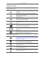
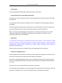
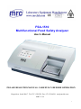
FSA-1510 Multifunctional Food Safety Analyzer User’s Manual PLEASE READ THIS MANUAL CAREFULLY BEFORE OPERATION Hagavish st. Israel 58817 Tel: 972 3 5595252, Fax: 972 3 5594529 [email protected] MRC.12.14 1 FSA-1510 User‟s Manual CONTENTS SYMBOLS DESCRIPTION ............................................................................................................................ 4 SAFETY PRECAUTIONS AND POTENTIAL HAZARDS ........................................................................ 5 1. INSTALLATION ........................................................................................................................................... 8 1.1 UNPACKING ............................................................................................................................................ 8 1.2 ENVIRONMENTAL REQUIREMENTS ........................................................................................................ 8 1.3 ELECTRICAL SETUP............................................................................................................................. 8 1.4 EXTERNAL PRINTER CONNECTION........................................................................................................ 8 2. FUNCTIONAL DESCRIPTION ................................................................................................................. 9 2.1 INTRODUCTION ...................................................................................................................................... 9 2.2 GENERAL DESCRIPTION ........................................................................................................................ 9 2.2.1 FSA-1510 front view .................................................................................................................. 9 2.2.2 FSA-1510 rear view ................................................................................................................. 10 2.3 TECHNICAL SPECIFICATIONS ............................................................................................................... 11 3. OPERATION INSTRUCTIONS ........................................................................................................... 12 3.1 TOUCH PANEL & PEN .......................................................................................................................... 12 3.2 DIGITAL NUMBER KEYBOARD .............................................................................................................. 12 3.3 CHARACTER SOFT KEYBOARD ............................................................................................................ 12 4. OPERATION .......................................................................................................................................... 13 4.1 POWER ON ........................................................................................................................................... 13 4.2 MAIN MENU .......................................................................................................................................... 13 5. PROGRAM ............................................................................................................................................ 14 5.1 MODE SETTING .................................................................................................................................... 14 5.1.1 ABS mode.............................................................................................................................. 14 5.1.2 Cut-Off mode ......................................................................................................................... 15 5.1.3 Calculation mode .................................................................................................................. 15 5.1.4 Calculation mode .................................................................................................................. 16 5.2 EDIT PROGRAM SETTING .................................................................................................................... 16 5.3 CREATING PROGRAM ........................................................................................................................... 21 5.4 DELETING PROGRAM ........................................................................................................................... 21 5.5 STANDARD ........................................................................................................................................... 21 6. RUN THE TESTS...................................................................................................................................... 23 6.1. PLATE PARAMETERS SETTING ........................................................................................................... 23 6.2. SELECT TEST PROGRAM.................................................................................................................... 24 6.3. MARK WELL.......................................................................................................................................... 24 6.3.1. Sample ................................................................................................................................... 25 6.3.2. Blank....................................................................................................................................... 25 6.3.3. Negative controls .................................................................................................................. 25 6.3.4. Positive controls .................................................................................................................... 26 6.3.5. Standard ................................................................................................................................. 26 6.3.6. Clear ....................................................................................................................................... 26 6.4. SELECT ALL ......................................................................................................................................... 26 6.5. CLEAR ALL ........................................................................................................................................... 26 6.6. TEST .................................................................................................................................................... 27 6.7. RESULTS .............................................................................................................................................. 27 2 FSA-1510 User‟s Manual 6.8. CALCULATION RESULTS ...................................................................................................................... 28 6.9. PRINTING ............................................................................................................................................. 29 6.10. 7. STORING TEST RESULTS ............................................................................................................ 29 REPORT ................................................................................................................................................. 30 7.1. REPORT FORM.................................................................................................................................... 30 7.2. REPORT BY SAMPLE LIST .................................................................................................................. 30 7.2.1 Edit sample data ....................................................................................................................... 31 7.2.2 Preview report ....................................................................................................................... 31 7.2.3 Delete sample data .............................................................................................................. 31 7.2.4 Print report ............................................................................................................................. 31 7.3 PRINT BY PROGRAM LIST .................................................................................................................... 31 8. 7.3.1 Preview report ....................................................................................................................... 32 7.3.2 Delete program ..................................................................................................................... 32 7.3.3 Print report ............................................................................................................................. 32 7.3.4 Gather print............................................................................................................................ 32 COMMUNICATION ............................................................................................................................... 34 8.1 COMMUNICATION TO PC........................................................................................................................ 34 9. SYSTEM SETTING .................................................................................................................................. 35 9. INFORMATION MANAGEMENT........................................................................................................ 37 11. POWER OFF ........................................................................................................................................... 39 12. INSTRUMENT SERVICE ...................................................................................................................... 40 12.1 MAINTENANCE ..................................................................................................................................... 40 12.2 CLEANING THE INSTRUMENT .............................................................................................................. 40 12.3 CHANGING PART OF INSTRUMENT ...................................................................................................... 40 12.3.1 Changing the fuses ................................................................................................................... 40 12.3.2 Changing the lamp .................................................................................................................... 40 12.4 TROUBLESHOOTING ............................................................................................................................ 40 13. SPARE PARTS REPLACEMENT ........................................................................................................ 42 13.1 REPLACEMENT OF LAMP ................................................................................................................... 42 13.2 REPLACEMENT OF FILTER.................................................................................................................... 42 13.3 REPLACEMENT OF FRONT-END BOARD ............................................................................................. 44 13.4 REPLACEMENT OF SMALL CART ........................................................................................................ 44 13.5 REPLACEMENT OF DRIVE BOARD ...................................................................................................... 45 13.6 REPLACEMENT OF LCD TRANSFER BOARD ........................................................................................ 46 13.7 ADJUSTMENT OF THE SPRING FIXER FOR MATCHING MICROPLATES ................................................... 46 13.8 HOW TO INSTALL THE PLATE TO THE PLATE HOLDER ........................................................................... 47 APPENDIX: THE NAMES AND THE CONTENTS OF THE TOXIC AND HARMFUL SUBSTANCES OR ELEMENTS IN THE PRODUCT .............................................................................. 48 3 FSA-1510 User‟s Manual Symbols description Symbols on the instrument This symbol means that the labeled item is hot while the instrument is in use. Don‟t touch the labeled item as you could be scalded. The symbol is labeled on the lamp support of optic system. This means that the labeled item could lead to personal injury and/or damage to the analyzer. The symbol is labeled beside the power outlet and some external interface. The symbols for “SERIAL NUMBER”, The serial number shall be after or below the symbol, adjacent to it. The symbol means the product is in vitro diagnostic medical device. The symbol indicates the manufacturer and its address, after which are shown its name and address. The symbol indicates EU representatives of the manufacturer and their addresses, after which are shown their names and addresses. The symbol indicates biological pollution, marked in the part where the instrument contacts the clinical reagent. The symbol appears in black side and yellow background. Symbols on the sales packaging The symbol means that the environment of instruments must be dampproof in the course of transport, and instrument must be kept in a dry environment. This means that instrument should handle with care in the course of transportation, so as not to damage it. The symbol means the instrument packaged should not be upended at any time The symbol means that the level piled up can't exceed 8 layers, as not to damage instrument. The symbol indicates temperature range of the analyzers during storage and transportation. 4 FSA-1510 User‟s Manual Safety Precautions and Potential Hazards General Before you start installing and working with the reader, you should read the safety precautions and regulations shown in this chapter. Operator Qualification Please note that the operation with Multifunctional Food Safety Analyzer should be carried out only by the inspector who has undergone necessary training provided by the sales agent. Service Technician Qualification To install, maintain and repair the instrument, a service technician has to be trained on the instrument by the manufacturer or their representative. A service technician is also expected to be familiar with the normal operation of the instrument as described in the User‟s manual and the special operations as described in the service manual. Electrical To use analyser safely, pay attention to the following items: To prevent the risk of electrical shock and/or damage to the instrument, Operator should not open the cover of the instrument. Only authorized personnel, for example, service technicians, may open the instrument to perform maintenance or repair. Touching the main board when the power is on may cause severe injury or death. Any problem, please ask for helps from your supplier. Mechanical There is no risk presented by the mechanical parts of the instrument when the instrument is closed. If the covers of the instruments are removed, mechanical parts could cause personal injury or the instrument may be damaged if the following advice is not being considered: DO NOT wear loose garments or jewellery that could catch in mechanisms. DO NOT put your fingers/hands into the pathway or any part while the instrument is in operation. DO NOT attempt mechanical repair unless the instrument is not in operation or OFF. Lamp The source lamp becomes extremely hot during operation; never touch the lamp when it is on! If the lamp needs to be changed, always switch off the lamp by switching off the instrument and then wait until the lamp has cooled down. Chemical The operator is responsible for taking all necessary precautions against hazards associated 5 FSA-1510 User‟s Manual with the use of clinical laboratory chemicals. Specific recommendations for each reagent used with the Reader are normally found on the manufacturer‟s package inserts or the on the product information sheets for each chemical. Wipe up any reagent spillage on the instrument immediately. Biohazardous Materials As with all vitro diagnostic equipment, sample samples that are assayed on this system, as well as all waste from the waste container, should be treated as the potentially biohasardous. All materials and mechanical components associated with the sampling and waste system should be handled according to your facility‟s biohazard procedure. Use the personal protective equipment recommended by your facility when handling any of these components. Detailed recommendations: - Samples Treat all samples as potentially biohaazardous and infectious. If any sample is spit on the instrument, utilize the correct personal protective equipment (PPE- gloves, lab coat, etc...), wipe it up immediately and clean the contaminated with a disinfectant. - Waste solutions and solid wastes Avoid direct contact with waste solution and/or solid waste. Both should be handled as potentially biohazardous. Dispose of waste solution and/or solid waste according to the relevant governmental regulations. Consult the reagent manufacturer for information on the concentrations of heavy metals and other toxic constituents in each reagent. - Biohazardous parts Avoid direct contact with the micropplate. Treat these parts as potentially biohazardous and /or infectious - Reagents Avoid direct body-contact with reagents. Direct body-contact may result in irritation or damage to your skin. Refer to the manufacturer‟s reagent kit box and package inserts, or product information sheets for specific instructions. Avoid direct body-contact with cleaning solution. Direct body-contact amy result in skin irritation or damage. Refer to the manufacturer‟s kit box and package inserts, or product information sheets for specific instructions. 6 FSA-1510 User‟s Manual Additional Precautions - Flammables Avoid using dangerous flammable material around the instrument. - Accuracy/Precision of the Measured Results For proper use of the instrument, measure control samples and monitor the instrument during the operation. An incorrectly measured result may lead to an error in diagnosis, thereby posing a danger to the sample. Treat all reagents according to the manufacturer‟s recommendations. Refer to the reagent kit box and package inserts, or product information sheets for specific instructions. Make sure that the sample/reagent mixture does not contain any blood clots, dust or other insoluble contaminants. If insoluble contaminants are contained in the sample, correct measuring values may not be obtained. - Application The instrument is designed for multifunctional food safety analyzer, involve pesticide residue detection, veterinary drug residues detection, antibiotic residues detection, organic pollutants measurement, natural toxins measurement, aquatic safety monitoring, and analysis of biological contaminants etc. Please note that other types of analysis may not be applicable to the instrument. - Operation and Maintenance During operation and maintenance of the instrument, proceed according to the instructors and do not touch any parts of the instrument other than those specified. Never leave a Reagents/sample mixture in the microplate for longer than necessary. Always clean the microplate after a batch of measurement and keep the microplate cleanliness when not in use. Verify the front covers closed while the instrument in operation. Avoid touching the mechanism, such as the sipper mechanism inside the instrument, while the instrument is operating. This may cause operation stop or damage the instrument. 7 FSA-1510 User‟s Manual 1. INSTALLATION 1.1 Unpacking Unpack FSA-1510 carefully and check for any damage that may have been caused during transportation. check the components:: FSA-1510 instrument 1 Operator‟s manual 1 Packing list Accessories:panel pen,power cable,print cable,RS-232 serial cable,lamp,fuses Keep the original package for future transportation Notice:report any damage or missing to your local representative。 1.2 Environmental Requirements Locate FSA-1510 to avoid exposure to excess dust, vibrations, strong magnetic fields, direct sunlight, draft, excessive moisture or large temperature fluctuations. Leave sufficient clearance (10 cm) at both sides of the unit for adequate air circulation. Notice : instrument be operated within an ambient temperature range of 0℃-40℃ and humidity ≤85%。 1.3 Electrical Setup Power requirements a.c.110-220V±10% 50-60±1Hz 120W warning: Ac power plug must be grounded at the main socket. The circuit used should be substantially free of large voltage transients such as large pumps, large centrifuges etc. If found smog, strange sound in instrument, please turn instrument off immediately and contact your dealer Connect the supplied power cable to the rear of the instrument as shown. Plug the other end of the power cable into an AC outlet. 1.4 External Printer Connection With both the instrument and the external printer off, connect the parallel cable to the rear of the instrument. Plug the other end of the parallel cable into the printer. Then plug power cable into printer. Install printer paper if needed. 8 FSA-1510 User‟s Manual 2. FUNCTIONAL DESCRIPTION 2.1 1) 2) 3) 4) 5) 6) 7) 8) 9) 2.2 Introduction FSA-1510 is a microprocessor –controlled, general purpose photometer system designed to read and calculate the result of assays, including contagion, tumorous mark, hemopathy, dyshormonism, which are read in microtiter plate. Touch panel let your operation easily. 100 pre-programmed tests. Multiple calculations: Absorbance mode (ABS) Cut-Off mode Single standard mode Point to point mode % Absorbance Multi-Point Mode Linear regression mode Exponent regression mode Logarithm regression mode Power regression mode visualization mark plate,you can set blank, control, sample ,standard in any place,and run mostly 12 different tests in one 96 microplate. Test time <5s/plate,and mix plate before test Max save 100 program and 1000 samples‟ data and 10000 sample records. generalization report ,support multi-type printers. information manage function : Department database, operator database, system log database. General Description 2.2.1 FSA-1510 front view ① ③ ② ④ ① power pilot lamp: It light when opens the instrument ② touch panel: display program ③ Plastic cover ④ Plate carrierer:Microplate in plate carrier 9 FSA-1510 User‟s Manual 2.2.2 FSA-1510 rear view ④ ⑤ ⑥ ⑦ ⑧ ① LINE PRINTER PO WER O N/O FF RS232 ACINPUT ①②③ ④ ⑤ ⑥ ① ② ③ ④ ⑤ ⑥ ⑦ ⑧ ② Power switch Sokect Fuses RS-232 interface SD interface USB interface Contrast adjust button RJ45 interface ③ 10 FSA-1510 User‟s Manual 2.3 Technical Specifications 0-4.500 A Measuring range: automatic single and double-wavelength Detection methods: Fully measurement, enzyme-linked immunosorbent assay, enzyme inhibition rate, kinetic, etc. Absorbance, threshold, single-point calibration, Calculating mode: point-to-point regression, multi-point percentage, linear regression, percentage logarithm, logarithmic curve, exponential curve, power curve, etc. Detection channel: 8 channels Wave length: Four wave lengths including 410、450、492(or 490) 、630nm are set, and additional four wave lengths are optional Resolution: 0.001A(display) ,0.0001A(internal calculation) liquid crystal display Display: Touch screen operation Operation mode: More than 100 test items, more than 10000 test results Storage: RS-232 bidirectional communicational interfaces, two USB Interface: interfaces ,SD card interface, Ethernet interface External printer Print: Power supply: a.c.110-220V±10%,50-60±1Hz Approximately 8kg Weight: Overall dimensions: 460mm(L)×330mm(W)×190mm(H) Operational 0℃~40℃;relative humidity≤85% environment: Storage: -10℃~40℃;relative humidity≤85% 11 FSA-1510 User‟s Manual 3. OPERATION INSTRUCTIONS 3.1 Touch Panel & Pen FSA-1510 has a touch panel; you can operator the instrument by pen. warning:please use the pen to touch the panel。 Notice:You also can use a RS-232 mouse to operate the instrument。 3.2 Digital Number Keyboard Input integer (age), float number (abs value), digital number (phone code), press “OK” button to saved, or press “cancel” button to exit and no saved. Edit :press ← button to del a character before cursor. Press “clear” button to clear all characters. 3.3 Character Soft Keyboard You can operator this keyboard like PC keyboard and move windows by dragging. 12 FSA-1510 User‟s Manual 4. OPERATION 4.1 Power on Switch the instrument on using power switch and wait 10 seconds ,you will see such display: instrument will self-check ,and initialization data will be load: Error report will be display if the instrument has not pass the self-check. 4.2 Main menu After self-check,system display main menu: 13 FSA-1510 User‟s Manual 5. Program Press “program” icon in main menu, Program list will be display: The FSA-1510 multifunctional food safety analyzer can set 100 test items, including 22 fixed items, which involve Food security analysis, pesticide residue detection, veterinary drug residues detection, antibiotic residues detection, organic pollutants measurement, natural toxins measurement, aquatic safety monitoring, and analysis of biological contaminants etc. 22 fixed items including: Pesticide Residues, Total Organophosphate Pesticides, Carbamate pesticides(Carbofuran), Herbicides Pesticides(Butachlor), Clenobuterol Hydrochloride, Ractopamine, Malachite green, Sudan, Enrofloxacin, Aflatoxin, Chloramphenicol, Diethylstilbestrol, Furaltadone, Nitrofurazone, Nitrofurantoin, Furazolidone, Sulfaquinoxaline, Sulfamethazine, Sulfadoxinemethoxy-pyrimidine, Methyl testosterone, five kinds of Residue of Sulfonamides(Sulfa 5 residues), three kinds of Residue of Sulfonamides(Sulfa 3 residues). 5.1 Mode setting FSA-1510 support 9 calculation modes: 5.1.1 ABS mode FSA-1510 only display and print out absorbance of samples. 14 FSA-1510 User‟s Manual 5.1.2 Cut-Off mode Cut-Off formula:Cov X NC Y PC Fac In this cut-off mode, where NC is the mean of the negative controls, PC is the mean of the positive controls, Cov is the cutoff absorbance .X, Y, Fac are coefficients that have any positive and negative numerical value (including 0 and 1) e.g. sample OD/NC≥2.1 is positive,that X=2.1, Y=0, Fac=0. In regular cutoff mode, FSA-1510 award that sample is positive if sample OD/Cov>1. 5.1.3 Calculation mode 1) 2) Single standard mode:A single calibrator material of known concentration is used so that concentrations of unknown samples may be calculated according to Beer‟s Law. Abs Conc. point to point mode:you can set 2-8 standards,the resulting calibrator curve is a series of lines connecting the calibrator points, which may be entered in ascending or descending order of absorbance. Abs 3) 4) Abs Conc. Conc. %ABS: You can set 2-8 standards. The highest absorbance standard will be assigned a value of 100, and each sample and standard is reported as a percent of the absorbance of the highest calibrator. The resulting calibrator curve is a series of lines connecting the calibrator points, which may be entered in ascending or descending order of absorbance. Linear regression mode: You can set 2-8 standards. This is a multi-point standard mode that calculates a best fit linear equation based upon the standard points. Equations: Y kX b :This is used when the absorbance and the concentration is linear. Abs Conc. 5) Index regression mode: You can set 2-8 standards. Equation: Y ke ; This is used bX 15 FSA-1510 User‟s Manual when the natural log of the absorbance is plotted against the concentration. 6) Logarithm regression mode: you can set 2-8 standards. Equation: Y kLnX b ; This is used when the natural log of the concentration is plotted against the absorbance 7) Exponent regression mode: You can set 2-8 standards. Equation: Y kX ; This is used b when the natural log of the absorbance is plotted against the natural log of the concentration. 8) Percent Logarithm regression mode: You can set 2-8 standards. Equation: (A/A0%=klogC+b); This is used when the natural log of the absorbance is plotted against the natural log of the concentration. 5.1.4 Calculation mode Enzyme inhibition rate(Two point) and Kinetics, Calculation of inhibition ratio Inhibition ratio (%) = (△AC-△AS)/ △AC×100% △AC:Absorbance difference of blank △AS:Absorbance difference of sample 5.2 Edit Program Setting Select existed program (it will be marked), press “Edit” button, it displays the following windows: Program: program name, don‟t input the name existed. Reagent: Input reagent name, you can ignore it. Wavelength calibration mode Double sample: If select it, samples must be pipetted into consecutive two wells, the mean absorbance reading will be used to calculate a single concentration. Double blank: If select it, blank must be pipetted into consecutive two wells, the mean absorbance reading will be used to calculate a single concentration. Blank: You can set range of the blank abs. If blank absorbance out of range, system will display: “blank abs is out of range.” You can press >> button,come to next windows, or press << button,come back this windows, you can press “cancel” button, exit program configuration windows. 16 FSA-1510 User‟s Manual 1) Standards mode setting windows: Standard number: you can select up to 8。 Concentration unit: you can select it from listing. Double standards: if select it, standards must be pipetted into consecutive two wells, the mean absorbance reading will be used to calculate a single concentration Standard conc.:double point standard conc. Listing, you can input standard concentration. 17 FSA-1510 User‟s Manual Notice: Standards may be entered in ascending order of absorbance. Standard 1 is the lowest concentration. 2) Cut-Off mode setting windows: The new software of FSA-1510 supports the user-defined formula. The following figure is showing. Math list: +, -, *, /, %, (,). Control: NC, NC, NC1, NC2, NC3, NC4, NC5, NCx, PC, PC1, PC2, PC3, PC4, PC5, PCx, CR, CR1, CR2, CR3, CR4, CR5, CRx, BLK. Logic list: >, <, <=, >=, AND, OR, = =. Type: Cut-off, Val1, Val2, Val3, Val4, Val5, Val6, Val7, Val8, and Val9. Cut-off: formula Val: formula Note: NC (PC, CR): Represents NCi and PCi when it acts as the range, other represents mean value (NCx, PCx and CRx) NCx, PCx and CRx: mean value of Nci, PCi and CRi. 18 FSA-1510 User‟s Manual “*” can not be omitted, such as 1.2*NCx. The “()” can not include the “AND, OR” Invalid input: 0.12<NC<0.4 Valid input NC>0.12 NC<0.4 “NC” and “PC” should not used with “OR” and “AND” “NC1<PC1 AND PC2<NCx” is permitted. For an example: Reagent instruction: Vironostika HIV Uni-Form II Ag/Ab The information following is from the reagent instruction. 12 Results Manual calculation Calculations must be made separately for each strip holder. NC = Absorbance of the negative control PC1 = Absorbance of the anti-HIV-1 positive control PC2 = Absorbance of the anti-HIV-2 positive control PC3 = Absorbance of the HIV-1 antigen positive control 1 2 3 4 5 Qualification of NC values NC must be < 0.250 Eliminate any NC≥0.250. Determine the mean (NCx) value of the remaining controls. NC must be≤ 1.4NCx. Eliminate any NC> 1.4NCx and recalculate NCx. NC must be≥ 0.6NCx. Eliminate any NC< 0.6NCx and recalculate NCx. Repeat steps 3 and 4 until no more outlier is found. 1 2 3 4 Assay validity An assay run is valid if More than half the number of the negative controls remain; PC1 - NCx≥0.600; PC2 - NCx≥0.600(if used); PC3 - NCx≥0.400 (if used). Cut-off value If the test run is valid, calculate the cut-off value NCx +0.100. A test sample is reactive if sample absorbance is≥cut-off value. A test sample is no reactive if sample absorbance is <cut-off value. Calculation example NC = 0.089; 0.096; 0.088 NCx = 0.091 PC1 = 1.549 PC2 = 1.523 PC3 = 1.398 Eliminate any aberrant control: NC ≥ 0.250 None eliminated 19 FSA-1510 User‟s Manual NC > 1.4NCx NC < 0.6NCx 1.4(0.091) = 0.127 0.6(0.091) = 0.055 None eliminated None eliminated Ensure the following is within specified acceptance criteria: PC1 - NCx ≥ 0.600 1.549 – 0.091 = 1.458 Pass PC2 - NCx ≥ 0.600 1.523 – 0.091 = 1.432 Pass PC3 - NCx ≥ 0.400 1.398 – 0.091 = 1.307 Pass Calculate cut –off value: Cut-off = NCx + 0.100 = 0.091 +0.100 = 0.191 Program: HIV-Ag/Ab Full name: HIV-Ag/Ab Reagent: First wavelength: 450 Second wavelength: None or 630 Calibration mode: Cut-off Double sample Blank≤0.050 Formula: 1. Type: Cut-off Cut-off: NCx +0.100 3. Type: Val2 Val3: NC>0.6NCx 5. Type: Val4 Val4: PC1 – NCx ≥ 0.600 2.Type: Val1 Val1: NC< 0.25 4.Type: Val3 Val3: NC< 1.4NCx 6.Type: Val5 Val4: PC2 – NCx ≥ 0.600 7. Type: Val6 Val4: PC3 – NCx ≥ 0.400 Qualitative: positive threshold value Negative < 1.000 Positive ≥ 1.000 Normal: 0.000 ─ 1.000 Finished. Range of Negative and positive: if absorbance of negative control and positive control is out of range, FSA-1510 calculates as min or max abs. Double of controls: if select this, controls must be pipetted into consecutive two wells, the mean absorbance reading will be used to calculate a single concentration Positive and negative setting windows 20 FSA-1510 User‟s Manual 3) Positive and negative setting windows Qualitative mode: In this option you can select regular cov, reverse cov, none. Regular cov: Samples with values higher than the positive cutoff are labeled as positive. Sample with values lower than the negative cutoff are labeled as negative. Any samples with values falling between the negative cutoff and the positive cutoff are labeled as equivocal. Reverse cov: Samples with values lower than the positive cutoff are labeled as positive. Sample with values higher than the negative cutoff are labeled as negative. None: you can select none if you don‟t award negative or positive. Normal range: please input the values with reagent instruction Press “Finished” button, come back program listing windows. 5.3 Creating program Press “new” button to create a new program, and then input the parameters. If the program name has existed, system will warn: “program exists.” 5.4 Deleting program Select one program in program listing, press “delete” button, system display windows: Press “Yes” button to delete program. Press “NO” button to cancel. 5.5 Standard Standard test results and curve will be stored. Operator can review and print the results. Select one program in program listing, Press “standard” button, system display standard conc. and abs. 21 FSA-1510 User‟s Manual Press “curve” button, system will display standard curve: Press “print” button, system will print standard curve. Notice : Old standards will be deleted if modifying program setting. (Wavelength, calculate mode, standard number, standard conc.etc.) 22 FSA-1510 User‟s Manual 6. RUN THE TESTS 6.1. Plate Parameters Setting Press “test” icon in main Pop up such windows: Plate direction: A-H direction and 1-12 direction. Test mode: You can select continue mode(<5 seconds= or step mode (<15 seconds =。 TowPoint or Kinetics mode: you can input the interval time which is the space rest between two running-test. Mixer setting: Mixer speed: you can select fast, normal, slow or none. Mixer time: you can select 1-60 seconds. Press “Ok” button, come to next windows. 23 FSA-1510 User‟s Manual 6.2. Select Test Program FSA-1510 support 12 programs in one plate, first press “New” button, the following windows display: select the program,press “OK” button. NOTICE: if you test multi-programs in one plate, you must set the programs one by one. STD: standard CLR: clear 6.3. Mark well You can set each well‟s function. Select well‟s function firstly, and click the well which you will mark. 24 FSA-1510 User‟s Manual mark label: sample:1–999 blank:B negative controls:NC positive controls:PC standard:S1–S8 Quality Control:QC 6.3.1. Sample Click the well which will be tested, then the well will be marked .If you modify sample No., please click that well again. A windows display: Input sample No.again.If you input No. already exist, system display “sample NO. Already exist, input again.” Notice : One sample is marked by only one sample NO. In one day. Negative controls: NC Positive controls: PC 6.3.2. Blank You can select blank well or no in different program. One program only set a blank well. Old blank value will be saved automatically and be used. 6.3.3. Negative controls You must set one negative control in one program other than negative control factor is 0.。 25 FSA-1510 User‟s Manual 6.3.4. Positive controls You can see negative control setting. (Section) 6.3.5. Standard This option is valid only when one program needs standards. If this program has old standards values, you can select set standards or not. Notice:If one program set standards and test good,new values of standards will cover old values. 6.3.6. Clear If you want delete marked wells, press “clear” button, then point wells that what you want. 6.4. Select All Use this button; you can quickly mark the sample wells. Press “select all” button, display such windows: input start number(1-999)and start well(row number and line number),press “Ok” button. All wells in this plate will be marked samples. Start No. is that you input. In this option all set program and wells will be deleted. You should set standards and controls after “select all”. 6.5. Clear All Press “Clear all” button, system display: 26 FSA-1510 User‟s Manual Press “yes” button, clear all well setting. 6.6. Test Press “start” button, system will test the plate: You can press “stop” button to stop the test. 6.7. Results The test results will be displayed: 1-6 columns abs results will be displayed, press 7-12>> button, windows will display 7-12 columns abs results. Sample: 001 is sample number, 0.040 is abs results. Notice:if abs results> 3.500A,will display 3.500*,and calculate by 3.500,if abs<0.000A,display 0.000*,and calculation by 0.000. you can modify the well result by click the well: Input abs value and press “ok” button. 27 FSA-1510 User‟s Manual Notice:Standard or control abs change will affect all results in this program! 6.8. Calculation Results Press “result” button in abs result windows, display calibration results: You can see the values and negative/positive mark display in every well. If the values in some well <0.0 ,“*” will be labeled to this well. 28 FSA-1510 User‟s Manual 6.9. Printing Notice:QTA: quantitative analysis QLA: qualitative analysis Press “Print” button in testing windows, FSA-1510 will print all test results. 6.10. Storing Test Results Press “cancel” button in Abs windows, the instrument will automatically store the test results in history database. 29 FSA-1510 User‟s Manual 7. REPORT 7.1. Report form Press “report” in main menu System displays such windows: Select report form: Report form: report by sample list or program list. Date range: today and all of days. 7.2. Report By Sample list Select “sample ”,press Ok button, display following windows: 1) 2) Select one sample Mark multi-samples:You can mark all samples by pointing first line in the title bar. 30 FSA-1510 User‟s Manual 7.2.1 Edit sample data Select one sample, press “Edit” button, sample‟s information windows pop up: Input the information. Press “Ok” button to save information, press “cancel” button to exit without save. 7.2.2 Preview report Select a sample, press “preview” button, that sample„s data display in list. 7.2.3 Delete sample data Press “delete” button, windows pop up: Press “yes” button, all marked sample data will be delete. Press “no” button, exit without save. 7.2.4 Print report Press “print” button, all marked sample report will be print. 7.3 Print By Program list Select “program”, press “ok” button, and pop up program list windows: 31 FSA-1510 User‟s Manual 7.3.1 Preview report Select one program, press “preview” button, and pop up preview windows: 7.3.2 Delete program Press “delete” button and “yes” button,all marked program and test data will be delete. 7.3.3 Print report Press “print” button, all marked program‟s standard curve and test data will be print. 7.3.4 Gather print FSA-1510 support gather print, you can quickly print all negative or positive sample data in one day. Press “gather” button, come to next windows: Input date, select program and results from list, press “OK” button, all samples coincidence condition display in listing windows: 32 FSA-1510 User‟s Manual Press “print” button, all data will be printed. 33 FSA-1510 User‟s Manual 8. Communication 8.1 Communication to PC 1) FSA-1510 can connect to pc, send data to pc.With software, you can store sample lists, print reports. For more information regarding pc software, contact your dealer. Connect serial cable to FSA-1510, and plug another end in pc COM1, turn on FSA-1510 and pc, Warning: FSA-1510 and PC don’t open when connecting serial port, otherwise hardware will be wrong. 2) Run pc external software, receive data. 3) Press “Data send” button in instrument 4) come to next windows,and press “start” buton to send: 5) 6) Sending data finished, press “Cancel” button to come back main menu. The external software will receive the data. 34 FSA-1510 User‟s Manual 9. SYSTEM SETTING Press “system” button in main menu: Come to the following windows: 1) 2) 3) 4) Serial NO Hospital: hospital name. Date and time Printer: FSA-1510 supports printers: PCL laser series, Epson ME 1+, SPRT-T, SPRT-RM, and HP P1007. You can choose one of printers Notice:Printers might be changed. Please reference to printer list of system setting. If printer setting is wrong, maybe printer works error. 5) 6) Sound switching:Turn on or off the speaker Touch panel calibration: You can calibration touch panel. Press “touch panel ” button, come to calibration windows: 35 FSA-1510 User‟s Manual Press the cross center by pen, wait one second, the cross moves to next place automatically. You should continue press cross with pen again. The same operation repeats 5 times, system will display next windows: Notice:The cross doesn’t move after pressing it. Please try it again. Please click anywhere in the panel, system will save new setting and come back system-setting windows. 36 FSA-1510 User‟s Manual 9. INFORMATION MANAGEMENT Press “Information” button in main menu: Come to the following windows: FSA-1510 has operator database and department database. You can add or delete operators/department in those databases. FSA-1510 can store 100 records in those two databases. Select operator or department. For example operator database: 1) add record :input operator name in the edit and press “add” button. If this operator‟s name already exists, system will display windows: 37 FSA-1510 User‟s Manual If database reach high range, system will report, “operator‟s record is over.” 2) Deltree record:Select one operator in operators listing, press “Delete” button: Press “Yes” button to deltree that record, press “No” button to cancel. 38 FSA-1510 User‟s Manual 11. POWER OFF Press “ ” button in main menu(in the right-bottom), display such windows: Press “yes” button, instrument will be turned off. Press “no” button, exit to main menu. Notice:If don’t turn off instrument normally, results and parameters edit in this time will not be save. System will display such windows: Warning:Please keep power when turn instrument off. The instrument may fail to operate normally if the power is interrupted. When data saved, such windows will display: Now you can turn the power switch off safely. Notice:Turn FSA-1510 off for at least 30 seconds and turn it on again. 39 FSA-1510 User‟s Manual 12. INSTRUMENT SERVICE 12.1 Maintenance FSA-1510 is designed to be a maintenance free instrument. To insure optimum trouble free performance, the instrument should be kept dry and operated in an area free from excessive dust. 12.2 Cleaning The Instrument Keep working environment clean Use a slightly damp soft cloth to remove dirt or spills. For decontamination, 70% isopropanol is recommended. Use soft cloth to remove dirt or spills in LCD. Notice:Use other chemicals or abrasive cleaners are not recommended. 12.3 Changing Part Of Instrument 12.3.1 Changing the fuses 1) 2) 3) Disconnect power cord from mains supply before replacing fuses. Open fuses box left in power, change fuses, close fuse box. Fuse specification:250V/3.15A. Turn the instrument on. Notice: Use the same fuse for replacing. 12.3.2 Changing the lamp 1) Turn the instrument off,open instrument cover by unscrewing the one screw on the front of the instrument. 2) Remove four screws of the optical assembly cover. Remove the cover. 3) Lift up the lamp with the terminal socket. Pull the terminal socket from the lamp contacts. 4) Refit the terminal socket to the contacts of the new lamp(OSRAM64607,6V/20W).Place the new lamp in its place. 5) Close the optical assembly cover. Replace the screws. 6) Close the instrument cover. Turn FSA-1510 on again. 12.4 Troubleshooting Symptom FSA-1510 does not Turn on Causes and Remedies Check power supply cord Check fuses Check power voltage Turn FSA-1510 off for 30 seconds and turn it back on. 40 FSA-1510 User‟s Manual Lamp does not light Check lamp Voltage Lamp is bad Change lamp RAM check error Turn FSA-1510 off for 30 seconds and turn it back on. Firstly turn FSA-1510 on and secondly turn printer on. Cable connect error, turn FSA-1510 off, open instrument cover, and reconnect cable between two pcb. Lamp is too high Filters install in wrong place. Lamp is too low Lamp is bad and changes it. Motor does not work Motor is bad Open the cover of the instrument, check motor. Chopper wheel run faster Chopper driver motor error Open the cover of the instrument, check chopper driver motor. Filter does not come back zero place Filter wheel error. Open the cover of the instrument, check sensor. Plate does not come back original place The plate may be does not place in right place. Check it. Plate don‟t move Driver Motor error, open cover, checks driver motor work or not. Open COM port error Turn Maybe use serial mouse. FSA-1510 off. Disconnect the mouse from instrument and turn on it again. Printer don‟t work Printer power works error. Check power is ok. Check ON/OFF button in printer. Check printer type in system setting right or not. Firstly turn FSA-1510 on then turn printer on. Check printer cable connect FSA-1510 right or not. The printing is dim or incomplete Change ink box, clean printer head. (See printer user manual) The printing is jam See printer user manual Other printer error See printer user manual Notice:For more information regarding service, contact you dealer. 41 FSA-1510 User‟s Manual 13. Spare parts replacement 13.1 Replacement of lamp Loosen a screw in the middle of the front-end of the machine and lift the top cover of the machine. Loosen the screws of the two black light-masking boards on the right of the machine and remove the two light-masking boards. Loosen the fastening screw of the bulb and disconnect the power cord of the bulb. Replace it with a new bulb and restore the instrument. Remove the screw, and then take out the lamp carefully 13.2 Replacement of filter STEP 1: Install filters 1. Turn off the instrument normally. 2. Remove the only one screw and open the cover of the Reader. Screw 3. Remove the four screws and take off the big black cover 4. Use a small cross screwdriver to loosen the three screws, which fix the filter wheel. Three small screws that fix the filter wheel 42 FSA-1510 User‟s Manual Figure 1 Then take the mirror assembly out Use the small alam key to remover these two screws. Figure 2 5. Use the small alam key to remover these two screws. 6. Plug out the filter wheel motor and take out the filter wheel including filters. 7. Use a forceps to install filter (e.g.520nm) in #4. From #0 to # 3 are the fixed filters, it should be moved. The gap of the wheel #4 #3 #5 #6 #2 #1 #7 0 Figure 2 Note: Don‟t touch the filters with your finger. 43 FSA-1510 User‟s Manual 8. Finish the install of filters, then install filter wheel with motor correctly. Remember to screw the three screws to fix the filter wheel. 9. Install the black cover, connect the power cable and turn on the instrument. 13.3 Replacement of front-end board Open the top cover of the machine and remove the light-masking board. Disconnect the power cord and signal cord of the front-end board and remove the fastening screw. Please note where the power cord and the small signal cord, which come from beneath the board, are connected before removing the old front-end board. Wedge the new front-end board in its proper position and connect the power cord and the small signal cord properly. Fix the screw in place. Note that the Hall module at the bottom right corner shall not stick up. Photocell Front-end board 13.4 Replacement of small cart Open the top cover of the machine and remove the light-masking board. Remove the two fastening screws under the fastening frame of the cart slideway on the right of the small cart. Remove the fastening frame of the slideway and remove the slideway. Loosen the belt‟s fastening screw at the top left corner of the small cart and turn the small cart by 180 degrees. Remove the small cart‟s fastening screw and replace the small cart with a new one. Fix the screw in place and turn the small cart by 180 degrees to restore it. Tighten the fastening screw to ajust the belt to a proper elasticity. Restore the slideway and the fastening frame. 44 FSA-1510 User‟s Manual Fastening frame Slideway The position of the belt‟s fastening screw 13.5 Replacement of drive board Open the top cover of the machine and remove the light-masking board. Remove the internal hexagonal screw used to fasten the working table and loosen the 3 screws used to fasten the optical fiber. Lift the working table with care and disconnect the wiring on the drive board. Remove the screws and replace the drive board with a new one. Restore the machine. (Note to protect the optical fiber during replacement; protect against static electricity; note not to confuse light-filtering plate motor cable with the 5pin power supply unit cable; note not to omit the insulative pad in installation.) Motor driving board 45 FSA-1510 User‟s Manual 13.6 Replacement of LCD transfer board Open the machine covers and remove the light-masking board. Disconnect the wiring on the transfer board and loosen the fastening screw. Replace it with a new board and restore the instrument. LCD transfer board 13.7 Adjustment of the spring fixer for matching microplates Because little difference among the different Microplates, it is allowed to adjust the position of spring fixer for matching the different Microplates. 1)Load the Microplate in the plate holder. 2) Remove the big screw in the front middle of the instrument then open the instrument upper cover. 3) Adjust the spring fixer‟s position for ensure that the plate holder could hold the Microplate properly. The figures are following: Note : The tension of spring fixer—— No vibration of microplate when vibrating around the Microplate; Easy to load the Microplate; No sound from the spring fixer when loading the Microplate. Spring fixer 46 FSA-1510 User‟s Manual 13.8 How to install the plate to the plate holder 1. Install one side to holder first, see Figure 1 Figure 1 2. Press another side of the plate down carefully. See Figure 2&e Figure3. Figure 2 Figure 3 47 FSA-1510 User‟s Manual Appendix: The names and the contents of the toxic and harmful substances or elements in the product 1. The names and the contents of the toxic and hazardous substances or elements Toxic / hazardous substance or element Part name Hexavalent Mercury Cadmium (Pb) (Hg) (Cd) Built-in PCB × ○ ○ ○ ○ ○ Casing × ○ ○ ○ ○ ○ × ○ ○ ○ ○ ○ × ○ ○ ○ ○ ○ Internal wire ○ ○ ○ ○ ○ ○ Accessories × ○ ○ ○ ○ ○ Display screen Optoelectric component chromium (Cr(VI)) Polybrominated Polybrominated Lead biphenyls (PBB) diphenyl ethers (PBDE) ○: Contents of this toxic/hazardous substance in all homogenous material of the component are below limit stated as per SJ/T11363-2006 standard. ×: Content of this toxic/hazardous substance at least in one homogenous material of the component is out of limit stated as per SJ/T11363-2006 standard. 2. ID Description Environmental protection service life ID ID meanings: This electronic information product contains certain toxic and harmful substances, and the environmental protection service life is 20 years, during the environmental protection service life, please feel free to use it, however, if beyond the environmental protection service life, please put it to the recycling system. 48