1
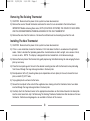
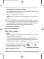
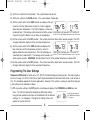
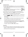
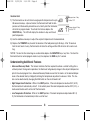
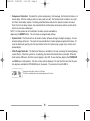
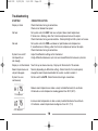
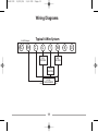
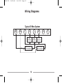
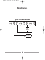
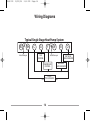
70810-IM
12/21/06
2:52 PM
Page 1
®
Model
70810
INSTALLATION AND OPERATING INSTRUCTIONS
5-2 Programmable Electronic
Thermostat Heat/Cool
70810-IM
12/21/06
2:52 PM
Page 2
Compatible with low voltage single stage gas, oil or electric heating or cooling systems and single stage heat
pumps. For use on 24VAC systems (not to exceed 30VAC) and 250mv to 750mv millivolt heating only systems.
WARNING!
• To prevent electrical shock and/or equipment damage, disconnect electric power to system at main fuse or circuit breaker box until installation is complete.
• Do not use this thermostat on applications with voltages above 30VAC. Wiring must conform to all local and
national building/electrical codes and ordinances.
• Do not short (jumper) across terminals on the gas valve or at the system control to test the installation. This
will damage the thermostat and void the warranty.
• This thermostat is equipped with automatic compressor protection to prevent damage due to short cycling.
The short cycle protection provides a 5-minute delay between heating (heat pump models) or cooling cycles to
prevent the compressor from being damaged.
• Do not switch the system to cool if the outdoor temperature is below 50 F (10 C). This may damage the cooling system and may cause personal injury. This thermostat should be used only as described in this manual.
SPECIFICATIONS
Electrical Rating:
Control:
Set Point Range:
Program:
Set Points:
Advanced Recovery:
Accuracy:
Terminations:
Power:
24 Volt AC (18-30 VAC)
1 Amp Maximum per Terminal
2 Amps Total Load
1 Heat / 1Cool Single Stage Heat Pump
45 F – 90 F (7.0 C – 32.0 C)
5 - 2 (Mon-Tue-Wed-Thur-Fri) & (Sat-Sun)
Morn, Day, Eve, Night
Yes
+/- 1 F (.5 C)
RC, RH, C, G, Y, W, B, O
24VAC
2
70810-IM
12/21/06
2:52 PM
Page 3
Removing The Existing Thermostat
1) CAUTION: Make certain the power to the system has been disconnected.
2) Remove the cover of the old thermostat and locate the wires that are connected to the terminal board.
IMPORTANT: Before removing these wires, NOTE (ON A PIECE OF PAPER) THE COLOR OF EACH WIRE
AND THE CORRESPONDING TERMINAL MARKING ON THE OLD THERMOSTAT.
3) Remove the wires from the terminals. Remove the old thermostat and mounting base from the wall.
Installing The New Thermostat
1) CAUTION: Make certain the power to the system has been disconnected.
2) If this is a new installation, locate the thermostat 4 to 5 feet above the floor in accordance with applicable
codes. Select a location that provides good airflow. Avoid locations in direct sunlight, near sources of heat,
or near air vents. NOTE: The display is designed to be best viewed from a front downward angle.
3) Remove the back plate of the thermostat by gently depressing the bottom locking tab and swinging the back
plate up and away.
4) Place the back plate against the wall in the desired mounting location with the thermostat wires protruding
from the wall through the large rectangular whole in the back plate.
5) Mark placement of the (2) mounting holes (oval shaped holes in back plate) on the wall, remove the back
plate, and drill (2) 3/16” holes.
6) Tap supplied plastic anchors into the holes.
7) Secure the back plate to the wall with the supplied screws making certain the thermostat wires have been
inserted through the large rectangular hole in the back plate.
8) Carefully attach the thermostat wires to the appropriate connections on the terminal board on the back plate.
Use the notes taken from step 2 of Removing The Existing Thermostat to determine their location on the new
thermostat. Reference wiring diagrams are available in the back of this manual.
3
70810-IM
12/21/06
2:52 PM
Page 4
9) Carefully place the thermostat body face down on a soft surface to expose the main circuit board. Gently
set the following switches in the correct position for the application.
• GAS / ELECTRIC: Configures the thermostat to either gas/oil or electric heating systems. For electric,
se the switch to HE. For gas, set the switch to HG.
• C / F: Sets the display in either Celsius or Fahrenheit.
• NORM / HP: Configures the thermostat for normal heating/cooling systems or heat pump systems (single stage).
10) Attach the thermostat body to the back plate by resting the top of the thermostat body on the two clips on
the upper portion of the back plate. Then gently press the front body into place until the bottom locking
tab snaps into place. NOTE: The terminal board pins must be properly aligned with the sockets on the
terminal board (on the back plate) in order for the front body to properly snap into place.
11) Set the system switch to the OFF position.
12) Set the fan switch to the AUTO position.
Testing The New Thermostat
WARNING!
• Do not switch the system to cool if the outdoor temperature is below 50 F (10 C). This may damage the
cooling system and may cause personal injury.
• This thermostat is equipped with automatic compressor protection to prevent damage due to short
cycling. The short cycle protection provides a 5-minute delay between heating (heat pump models) or
cooling cycles to prevent the compressor from being damaged.
1) Restore the system power. The LCD (liquid crystal display) will
alternately display the time and room temperature. The LCD will
illuminate at the touch of the red or blue arrow keys. LCD will
return to its normal state after 10 seconds.
4
Image shows display altering between time and a
room temperature of 70
70810-IM
12/21/06
2:52 PM
Page 5
2) Set the fan switch to the ON position. The system blower should start.
3) Set the fan switch to the AUTO position. The system blower should stop.
4) Set the system switch to the HEAT position and depress the red
arrow key until the temperature set point is at least 3 degrees
above the room temperature. The LCD will display a flame icon
to indicate heat. The heating system should start within several
seconds (the system blower may not come on immediately).
Image shows room temperature of 71 and Heat set
point of 75 as the display alternates every 3 seconds.
5) Set the system switch to the OFF position. The system should shut down within several seconds. The LCD
will again alternately display the time and room temperature.
6) Set the system switch to the COOL position and depress the
blue arrow key until the temperature set point is at least 3
Image shows room temperature of 76 and A/C set
degrees below the room temperature. The LCD will display a
snowflake icon to indicate A/C. The cooling system should start point of 73 as the display alternates every 3 seconds.
within several seconds. WARNING: Do not perform this test if the outdoor temperature is below 50 F.
7) Set the system switch to the OFF position. The system should shut down within several seconds. The LCD
will again alternately display the time and room temperature.
Programming The User Settings
Temperature Differential is factory set at .5 F (0.25 C) for both heating and cooling cycles. The room temperature must change .5 F (0.25 C) from the set point temperature before the thermostat will initiate a call for heat or
A/C. This should be appropriate for most applications. However, if the system is cycling on and off too frequently, the setting can be adjusted as follows.
1) With the system setting in the OFF position, simultaneously depress the PROGRAM and RUN keys two
times. The LCD will display the temperature differential setting.
Image shows temperaUsing the red and blue arrow keys set the differential to the desired
ture differential setting of
0.5 degrees.
setting of .5, 1, or 2 degrees. The higher the setting, the less frequently the system will cycle.
5
70810-IM
12/21/06
2:52 PM
Page 6
2) When the desired setting is made, release the key and the unit will automatically store the setting after 15
seconds.
Programming & Operating The New Thermostat
Setting the Time & Day
1) With the thermostat in set at either COOL, OFF, or HEAT, depress the TIME/DAY key. The hour will flash.
Using the red/blue arrow keys, set the correct hour.
2) Depress the TIME/DAY key a second time. The minutes will flash. Using the red/blue arrow keys, set the
correct minutes.
3) Depress the TIME/DAY key a third time. The day will flash. Using the red/blue arrow keys, set the correct
day. The display will stop blinking after 15 seconds and the time and day settings will be stored.
Setting the Heating & Cooling Programs
The thermostat includes a factory set program that will adjust the temperature 4 times per day (MORN, DAY,
EVE, NIGHT) Monday through Friday and Saturday/Sunday. This program can be customized using the steps
below.
Factory Set Program
Program
MORN
DAY
EVE
NIGHT
System
Heat
Cool
Heat
Cool
Heat
Cool
Heat
Cool
Weekday
6:00am - 70°F (21.0°C)
6:00am - 75°F (24.0°C)
8:00am - 62°F (16.5°C)
8:00am - 85°F (29.5°C)
6:00pm - 70°F (21.0°C)
6:00pm - 75°F (24.0°C)
10:00pm - 62°F (16.5°C)
10:00pm - 78°F (25.5°C)
6
Weekend
6:00am - 70°F (21.0°C)
6:00am - 75°F (24.0°C)
8:00am - 62°F (16.5°C)
8:00am - 85°F (29.5°C)
6:00pm - 70°F (21.0°C)
6:00pm - 75°F (24.0°C)
10:00pm - 62°F (16.5°C)
10:00pm - 78°F (25.5°C)
70810-IM
12/21/06
2:52 PM
Page 7
Customizing the Program
1) Set the System switch to the HEAT or COOL position and the Fan switch to either the AUTO or ON position. NOTE: In AUTO, the system blower will run only when the A/C or heat is running. In ON, the system
blower will operate continuously.
2) Depress the PROGRAM key. LCD will display an image similar to the following. The set
point temperature will blink and the time will be displayed.
3) Use the red/blue arrow keys to select the set point temperature for the Morning program Mon – Fri.
4) While the temperature is still blinking, press the TIME/DAY key to set the time for the Morning program.
The time in the LCD will blink. Use the red/blue arrow keys to select the correct time.
5) Set the remaining Day, Evening, and Night times and temperatures for the Mon – Fri. and Sat/Sun periods:
• Depress the PROGRAM key to select the desired period. (Each depression of this key cycles the menu
to the next period.)
• Depress the Time/Day key to switch between time settings and temperature settings at each period.
• Use the red/blue arrow keys to increase/decrease the time and temperature settings.
• The settings are automatically stored 15 seconds after the last touch of a key. NOTE: If the programming at any period is not completed and the display stops blinking, depress the PROGRAM key as necessary to cycle back to the desired period to be programmed.
• This procedure is required for both the COOL and HEAT system settings
Temporary Hold
1) Use the red/blue arrow keys to temporarily raise or lower the set point temperature at any time during normal operation. The temperature will hold at the new level UNTIL the next program period begins at which
point the thermostat will return to the program temperature.
7
70810-IM
12/21/06
2:52 PM
Page 8
Vacation Hold
1) The thermostat can be set to hold a single specific temperature for up to
30 consecutive days. Upon activation, the thermostat will hold the temperature until the duration period times out at which point the thermostat
will return to program mode. To activate this feature, depress the
VACATION key. The LCD will display the duration in days and the set
point temperature.
Image shows 1 day
hold at 73 F
Image shows 25 day
hold at 71 F.
2) Use the red/blue arrow keys to adjust the set-point temperature to the desired level.
3) Depress the TIME/DAY key to select the duration of the hold period (up to 30 days). After 10 seconds
from the last touch of a key, the thermostat will store the setting and the LCD will return to its normal setting.
NOTES: To view the time remaining on vacation hold, depress the VACATION key at any time. To return the
thermostat back to normal program mode at any time, depress the RUN key for 1 second.
Understanding Additional Features
• Advanced Recovery Mode: This feature minimizes the time required to achieve a comfort setting after a
set back period. During normal operation, the thermostat will gradually change to the set point temperature
prior to the actual program time. Advanced Recovery Mode ensures that the room is at the desired temperature at the desired time by intelligently initiating the temperature adjustment in advance. Note: This feature can be deactivated by changing the ARM switch on the circuit board to off.
• High Temperature Protection: While in the HEAT position, if the room temperature reaches 93 F (34 C),
the thermostat will automatically shut off. In the unlikely event the room temperature reaches 99 F (37 c), a
mechanical bimetal switch will shut off the thermostat.
• Low Temperature Protection: While in the HEAT position, if the room temperature drops below 40 F (4
C), the thermostat will automatically initiate a call for heat.
8
70810-IM
12/21/06
2:52 PM
Page 9
• Compressor Protection: To protect the system compressor(s) from damage, the thermostat features a 5
minute delay. After the cooling system (or heat pump turns off), the thermostat will not allow it to re-start
until the 5 minute delay expires. A blinking snowflake/flame indicates this feature has been activated.
Once the 5 minute delay expires, the snowflake/flame will illuminate continuously and the system will be
able to re-start when called upon.
NOTE: For the purpose of unit installation, this delay can be overridden by
depressing the RESET button. This will erase any programmed settings.
• System Reset: The thermostat can be reset to factory software settings including the program. All user
entered settings will be lost. The reset will also override the 5 minute compressor protection feature. To
reset the thermostat, gently press the reset button on the front panel using a paper clip or similar small
pointed object.
• Filter Change Reminder: The thermostat features a reminder for the user to change the heating/cooling
system filter(s). When the system fan is operating, the internal thermostat timer is activated. When the
timer reaches 500 hours, the filter icon will appear in the LCD. To view the time, depress the PROGRAM
and RUN keys simultaneously. The time in hours will be displayed. To reset the filter icon from this position, depress and hold the PROGRAM key for 3 seconds. The counter will reset to 000 Hr.
Image shows the filter counter at 208 hours.
The filter icon illuminates in the primary display at 500 hours.
9
70810-IM
12/21/06
2:52 PM
Page 10
Troubleshooting
SYMPTOM
CORRECTIVE ACTION
Display is blank
Check thermostat wiring & connections.
Check circuit breaker/fuse panel.
No heat
Set system switch to HEAT and raise set point above room temperature.
If flame icon is blinking, allow the 5 minute compressor lock-out to expire.
Check thermostat wiring and connections. Check pilot light or HSI system on furnace.
No cool
Set system switch to COOL and lower set point below room temperature.
If snowflake icon is blinking, allow the 5 minute compressor lock-out to expire.
Check thermostat wiring & connections.
System turns on/off
too frequently or
not enough
Adjust the differential setting on the thermostat.
A high differential decreases cycle rate and a low differential increases cycle rate.
Display is not illuminated
Touch the up or down arrow key. Display will illuminate for 10 seconds.
Room temperature and
set point disagree
Normal (depending on differential setting). Check for drafts that could quickly
change the room temperature before the system is able to correct it.
System fan runs
continuously
Set fan switch to AUTO. Check thermostat wiring & connections.
Reduce room temperature or allow a newly installed thermostat to acclimate.
HI indicates a room temperature reading greater than 90 F (32 C).
HI is displayed
Increase room temperature or allow a newly installed thermostat to acclimate.
LO indicates a room temperature reading less than 45 F (7 C).
LO is displayed
10
70810-IM
12/21/06
2:52 PM
Page 11
Wiring Diagrams
Install Jumper
RC
RH
Typical 4-Wire System
C
G
Y
FAN
CONTROL
W
HEAT
CONTROL
COOL
CONTROL
HOT
24 VAC
TRANSFORMER COM
11
B
O
70810-IM
12/21/06
2:52 PM
Page 12
Wiring Diagrams
Typical 5-Wire System
RC
RH
C
HOT
G
Y
FAN
CONTROL
COOL
CONTROL
COOL 24 VAC
TRANSFORMER
12
W
HOT
COM
B
O
HEAT
CONTROL
HEAT 24 VAC
TRANSFORMER
COM
70810-IM
12/21/06
2:52 PM
Page 13
Wiring Diagrams
Typical 2-Wire Millivolt System
RC
RH
C
G
W
Y
B
O
HEAT
CONTROL
HOT
13
24 VAC
TRANSFORMER
COM
70810-IM
12/21/06
2:52 PM
Page 14
Wiring Diagrams
Typical Single Stage Heat Pump System
RC
RH
Install Jumper
C
G
W
Y
FAN
CONTROL
B
Install Jumper
COMPRESSOR
CONTROL
HOT
24 VAC
TRANSFORMER
14
O
REV. VALVE
COOL ENERGIZED
REV. VALVE
HEAT ENERGIZED
COM
70810-IM
12/21/06
2:52 PM
Page 15
Warranty
ONE YEAR LIMITED WARRANTY
Motors & Armatures Inc. warrants each new MARS thermostat against any defects due to
non-conforming material or workmanship for a period of one year after the original date of
purchase by a professional service technician and does not include the cost of removal or
re-installation. This warranty extends to the contractor or dealer who purchased the
product from a wholesaler. For warranty claims, consumers should contact the contractor
or dealer who installed the thermostat.
This warranty and Motors & Armatures’ liability does not include damage to merchandise or
thermostat resulting from accident, alteration, neglect, misuse, improper installation, or any
other failure to follow Motors & Armatures’ installation and operating instructions. Contact
Motors & Armatures Inc. for full details on product warranty policy.
Motors & Armatures Inc.
250 Rabro Drive East
Hauppauge, NY 11788
15
70810-IM
12/21/06
2:52 PM
Page 16
INSTALLATION AND OPERATING INSTRUCTIONS
5-2 Programmable Electronic Thermostat Heat/Cool
Model
70810
®