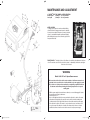
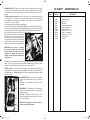
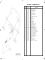
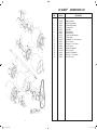
1
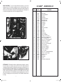
Warranty Conditions Owners Manual Australia & New Zealand Only Rover Mowers Limited warrant that this machine is free from defects in material and workmanship. This warranty is limited to making good or replacing any part which appears upon inspection by the manufacturer or his agent to be defective in material or workmanship. The engine used to power this machine is warranted by the manufacturer whose warranty statement has been included with the machine. As the warranty for the engine may differ from the warranty for the other components, you are advised to read the engine manufacturer’s warranty carefully For other items this warranty shall apply for a period of 12 months from the date of purchase except for products used commercially where the warranty is limited to 90 days. This warranty does not obligate the manufacturer, his agents or dealers to bear the transport costs incurred in the repair or replacement of any defective part. This warranty excludes fair wear and tear, or any damage caused by misuse or abuse. Parts such as blades, blade bolts, v-belts and spark plugs, which can be subjected to use beyond their normal intended working capacity are also excluded. This warranty is void if parts other than genuine have been used or if repairs or alterations have been made without the manufacturer’s written authority. The above warranty does not exclude any condition or warranty implied by the Trade Practices Act 1974 or any other relevant legislation which implies any condition which cannot be excluded. REMEMBER: PROOF OF PURCHASE IS THE RESPONSIBILITY OF THE OWNER AND IS NECESSARY PRIOR TO WARRANTY WORK BEING UNDERTAKEN. REPAIRS MUST BE CARRIED OUT BY AN AUTHORISED ROVER DEALER /SERVICE AGENT AND GENUINE SPARE PARTS MUST BE USED OR YOUR WARRANTY WILL BE VOID. QUEEN TM 30” REEL MOWER Online Warranty Registration - www.rovermovers.com.au For your record: Dealer’s Name:.............................................................................................................. Dealer’s Address:........................................................................................................... Dealer’s Phone No:........................................................................................................ Product Model No:........................................................................................................ Product Serial No:.......................................................................................................... Date of Purchase:........................................................................................................... Rover Mowers Limited reserves the right to make changes of and add improvements upon its product at any time without notice or obligation. The Company also reserves the right to discontinue manufacture of any product at its discretion at any time. ISO 9001 Lic 10168 Standards Australia A.B.N. 11 000 257 303 Rover Mowers Australia PO Box 1235 Eagle Farm. Qld 4009 Australia. S1943676 Rev. C. 3676 Queen 30 Reel Mower.indd 1 RECYCLED PAPER This Rover Owners Manual has been printed on 100% Australian recycled paper as a sign of Rover Mowers’ commitment to Greening Australia and New Zealand. GWAIL GROUP PRINTED IN AUSTRALIA Rover Mowers New Zealand East Tamaki, Auckland. New Zealand. TM © Copyright 11/2005 22/11/2005 4:27:30 PM SAFETY INSTRUCTIONS * A mower user must be in good physical condition and mental health and not under the influence of any drug or alcohol which might impair vision, co-ordination or judgement. * When starting, do not wrap the starter rope around your hand. Do not allow the starter cord to snap back. Return the starter grip slowly to allow the cord to rewind properly. * Strictly follow the operator instructions before attempting to start engine. * Do not use a mower when tired or fatigued. Lack of alertness may cause serious injury. * Never leave wind-up starters in a wound position. * Know your controls. Read and Understand Owner’s Manual before operating mower. Learn how to stop the mower in an emergency. Refer to Operator’s Instructions. * Never mow where machine could tip or slip. * On slopes or wet grass be extra careful of your footing. * Never cut grass by pulling mower towards you. * Do not lend or sell the mower without the Owner’s Manual. * Be extremely careful when using a mower on slopes. Stay alert for holes in the terrain and other hidden hazards. * Be sure that anyone using the mower reads and fully understands how to safely operate the mower. * Stop the engine before pushing the mower across gravel drives, walks or roads. * Never mow whilst bystanders or pets are present in the mowing area. * Never over-speed the engine or alter the governor settings. Excessive speed is dangerous and shortens mower life. * Never mow while barefoot or wearing open sandals or thongs. Wear long trousers and heavy non-slip shoes. * Stop the engine whenever you leave the mower even for a moment. * It is advisable to wear suitable eye protection when operating a mower. * Stop the engine and disconnect the spark plug wire and inspect mower if: (a) The mower begins to vibrate abnormally; or * Before using, always visually inspect to see that the blades, blade bolts and cutter assembly are not worn or damaged. Replace worn or damaged blades and bolts in sets to preserve balance. (b) After striking a foreign object. Repair any damage before continuing further operation of the mower. * Damaged blades and worn bolts are major hazards. * Stop the engine and disconnect the spark plug wire before clearing blockages, checking or working on the mower. * Replace worn or faulty silencers. * Never pick-up or carry a mower when it is operating. * Make sure the area to be moved is cleared of sticks, stones, bones, wire and debris. They could be thrown by the blades. * Where fitted, turn fuel tap off at the conclusion of the mowing. * Store fuel in a cool place in a container specifically designed for the purpose. In general, plastic containers are unsuitable. Handle fuel carefully. It is highly flammable. * When transporting in a vehicle, secure the mower to prevent movement, roll-over, fuel spillage, and mower damage. * Keep all nuts, bolts and screws tight to be sure the equipment is in a safe working condition. * Refuel outdoors only. Do not smoke when refuelling engine. Add fuel before starting engine. Never remove the cap from the fuel tank or add petrol while engine is running. Allow engine to cool for several minutes before refuelling if engine is hot. If petrol is spilled, do not attempt to start the engine, but move the mower away from the area of the spill and avoid creating any source of ignition until the petrol vapours have dissipated. * Never modify the mower in any way. Use only replacement parts made and guaranteed by the original manufacturer of your mower. * Keep all safety devices (guards and switches) in place and working. ITEM 1 2 3 4 5 6 7 8 9 10 11 12 13 14 15 16 17 18 19 20 21 22 23 24 25 26 27 28 29 30 31 32 33 34 PART No. 1674306 1661253 306405 655517 655525 655509 A20202 A20203 A20201 1661245 A20200 1551265 1661775 303124 305373 A20212 306333 306368 509819 301648 A02050 A02163 2061886 A02216 A02193 A02110 A02033 A02220 A02278 2062724 A02107 A02209 A02235 655533 DESCRIPTION Electric motor Plug- WIP 410B male Conduit Plug mounting bracket Plug insulating mount Mount cap Earth wire Earth wire Electrical wire- red Socket- WIP 0410 female Electrical wire- black Plastic conduit- flexible Cable clamp Conduit clip Conduit Switch Motor cover Cable gland Decal- Scott Bonnar Decal- warning Nut- 3/16” square pressed Screw- 3/16” x 1/2” mush.head M/T. Screw- 3/16” x 1/2” cheese head M/T. Washer- 3/16” x 1/2” x 20g.flat Nyloc nut- 3/16” unc.thin Setscrew- 3/8” x 1” unf.HT. Washer- 3/8” x 3/4” x 16g.flat Nyloc nut- 3/8” unf.hex. Bolt- 3/8” x 3-3/4” unf.HT. Screw- 3/16” x 1” cheese head M/T. Screw- 1/4” x 1/2” unc.Slotted Mush.head Washer- 1/4” x 5/8” x 18g.flat Nyloc nut- 1/4” unc. Reset cover * Keep the engine free of grass, leaves or excessive grease – these can be a fire hazard. * Remove the fuel cap slowly to relieve fuel tank pressure. * Store the mower in a well ventilated room away from naked flames such as may be found in hot water heaters. * Check for fuel leaks while refuelling or using the mower. If fuel leak is found, do not start or run the engine until the leak is fixed and spilled fuel is wiped away. * Walk, Never Run. * Take care not to get fuel on your clothing. If this occurs, change your clothing immediately. To emphasise special information the words WARNING and CAUTION are used. * Do not operate mower in confined space where exhaust fumes (carbon monoxide) can collect. WARNING: The safety of the user and others is involves. Personal injury may result should this information be disregarded. CAUTION: Follow these instructions carefully to avoid mower damage and loss of warranty. * Mow only in good daylight. * Start the engine carefully with feet well away from the blades. * Disengage all blade and drive clutches before starting. 1 3676 Queen 30 Reel Mower.indd 2 30” QUEENTM - SPARE PARTS LIST 26 22/11/2005 4:27:30 PM MAINTENANCE AND ADJUSTMENT 30” QUEENTM ELECTRIC MOWER 2 SPEED OPERATION Normal Speed _ 4.9km/p.h 127 cuts per metre. Low Speed _ 3.2km/p.h 183 cuts per metre. SPEED CONTROL To change speed, stop motor and move ribbed sliding sleeve (A) inwards to engage normal speed or outwards for low speed as required. It may be necessary to twist the sleeve or countershaft backwards and forwards slightly whilst sliding the sleeve position to allow the gear teeth to line up and mesh fully. FRONT ROLLER – The height of the cut of the Mower is controlled by the adjustment of the front roller. The machine cuts lower if the front roller is raised, or alternatively, the machine cuts higher if the front roller is lowered. WARNING Model 300433 415 volt 3 phase QueenTM mower Before use the rotation of the electric motor mounted on the QueenTM mower has to be checked for the correct direction of rotation with the local power supply to be used. This is at the onus of the purchaser and must be completed by a qualified electrician. Use extreme caution when performing the following inspection due to exposed rotating parts. 1. 2. 3. 4. With the power supply disconnected remove the motor cover and disengage all clutches. Connect the power supply to the mower. Switch the power on. Move to the right hand side of the mower and note the direction of rotation of the motor pulley when looking directly at the end of the motor shaft. It should be rotating in the clockwise direction (left to right). Switch the motor off and disconnect the power supply. 5. If the direction of rotation of the motor is correct replace the motor cover and proceed to use the mower. If the direction of rotation of the mower shaft is incorrect contact a qualified electrician to have the motor rotation reversed to suit your power supply. 25 3676 Queen 30 Reel Mower.indd 3 2 22/11/2005 4:27:31 PM HEIGHT ADJUSTMENT – To cut lower, slacken quadrant clamp bolt nuts (1), also the lower adjusting screw nut (2). Then tighten top adjusting screw nut (3) until desired height of cut is obtained. To cut higher, reverse procedure. Re-tighten all nuts after desired setting is obtained. The indicator marks on the quadrant are an indication of the cutting height, but to set the height of cut accurately the setting gauge must be used. Refer setting gauge instructions. 30” QUEENTM - SPARE PARTS LIST ITEM PART No. 1 2 3 4 5 6 7 8 9 10 11 12 13 14 15 16 17 18 19 20 21 22 23 24 25 26 27 28 29 30 31 32 33 34 35 36 A80084 305584 1661150 1661775 1551265 A20207 A20206 306368 1661235 303124 A20211 306341 305373 A20209 A20208 301649 509819 318228 2062724 A02050 2061886 A02216 A02193 A02163 A02023 A02039 2072711 A02044 232116 A02017 A02209 A02235 655533 A20044 A20210 A20213 DESCRIPTION Electric motor Plug mounting bracket Plug- male Cable clamp Plastic conduit- flexible Electrical wire- red Electrical wire- black Cable gland Plug- female Conduit clip Switch Motor cover assembly Conduit Earth wire Earth wire Decal- warning Decal- Scott Bonnar Setscrew- 1/4” x 3/4” unf.HT. Screw- 3/16” x 1” cheese head M/T. Nut- 3/16” square pressed Screw- 3/16” x 1/2” cheese head M/T. Washer- 3/16” x 1/2” x 20g.flat Nyloc nut- 3/16” unc.thin Screw- 3/16” x 1/2” mush.head M/T. Nut- 5/32” unc.hex. Washer- 5/32” shakeproof Screw- 5/32” x 1” bsw.csk. Washer- 1/4” shakeproof Nut- 1/4” unf.hex. Screw- 1/4” x 1/2” unc.Slotted Mush.head. Washer- 1/4” x 5/8” x 18g.flat Nyloc nut- 1/4” unc. Reset cover Reset switch Trip wire Electrical wire- red reset switch SETTING GAUGE – This illustrates the method of setting the gauge to the height of cut, where in this instance height of cut is a twenty cent piece and a five cent coin. The distance between the setting gauge bar and the underside of the adjustable screw head represents the height of cut. Lock the screw in the desired position with the wing nut. To use the setting gauge, rest it against the underside of the front and rear rollers, as illustrated, and by adjusting the front roller, the desired height of cut will be obtained when the underside of the screw head lightly touches the top cutting edge of the bottom blade across its full width. When using the setting gauge, take care not to force the head of the adjusting screw onto the bottom blade, as this could distort the blade and affect the setting. 3 3676 Queen 30 Reel Mower.indd 4 24 22/11/2005 4:27:33 PM TO CHECK THE MOWER FOR ALIGNMENT – Your mower is designed to produce the perfectly flat cut that is required for a top quality green. Ridging or stepping between cuts means that the height of cut is unevenly set or more likely, that the mower is “out of square” – That is, the rear roller is not perfectly in line with the cutting edge of the bottom blade. This condition can be brought about by transport of the mower or undue stress caused by bumping while moving from the equipment shed onto the green. Re-alignment can be achieved by different means but the recommended procedure is – Lay the mower back on the handle. Chalk the thin front edge of the bottom blade about 6” of is length at both ends. With the front roller remaining in approximately its normal height setting, “sight” the bottom of the front roller relative to the chalked cutting edge of the blade. Adjust the front roller into exact alignment with the cutting edge, continually sighting while adjustment proceeds. Lock the roller and recheck. Now use your height setting bar as an aligning tool by placing the bar against the front roller and the rear roller on the extreme LEFT HAND SIDE. (Chain Cover Side) Adjust the setting bar screw so that it just contacts the bottom blade cutting edge. Test the right hand side of the rollers with the same setting, and adjust the rear roller up or down until the same screw contact is achieved on the blade. As the movement of the rear drum could affect the original L.H.S. setting slightly, reset the screw at the L.H.S. and recheck the R.H.S. All elements of your machine will not be in perfect alignment. After tightening all adjustments a final check should be made. The required height of cut can now be checked and set in the normal manner. While the procedure may seem complicated it is in fact very simple to perform and can be carried out in less than 15 minutes. The sighting is easy and accurate because it is done from the front roller which is nearest to the operator. A machine that is “true” will pay dividends by precision cutting of your green. CUTTER – To adjust the cutter setting, slacken cutter hanger clamp bolts (4) at each side of the machine, and proceed as follows: Adjustment – Slacken the top nuts (5) on adjusting screws. Then by tightening the bottom nuts (6), the cutter is lowered on to the bottom blade. To raise the cutter, loosen the bottom nuts and tighten the top nuts. Re-tighten cutter hanger clamp bolt nuts. Always adjust cutter to bear very lightly on bottom blade. If the cutter rubs harshly on the bottom blade, there will be excessive wear of both cutter blades and bottom blade, and an unnecessarily heavy load on the power unit. A grass trough is incorporated that can be adjusted closely to the rear drum so that grass and dirt build-up is scraped from the drum and caught in the trough. TO EMPTY – Remove the cover plate from the trough opening in the side frame. The cover unclips by pivotting it upward. Withdraw the trough, as illustrated. When replacing, the end of the trough could come into contact with its adjusting screw, when half way in. A twisting action will allow the bottom edge of the trough to clear the screw and to push right in. Replace the cover plate. NOTE – The trough can be withdrawn more easily if the deflector clamp bolts are loosened and the deflector lowered to allow extra clearance. ADJUSTMENT – The adjusting screw can only be operated when the trough is removed as it is located under the centre of the trough. To adjust trough closer to roller, release lock-nut and lower screw slightly – to move it away, raise screw slightly. Replace trough and check clearance from the drum. If satisfactory withdraw trough and tighten lock-nut. 23 3676 Queen 30 Reel Mower.indd 5 4 22/11/2005 4:27:34 PM REVERSING CUTTER – A feature of this machine is that the cylinder may be easily removed, reversed end for end and replaced. This provides a new keen cutting edge. If the bottom blade is badly worn, this should be replaced at the same time that the cutting cylinder is reversed or replaced. To withdraw cutter from machine, first remove cutter chain (7), sprocket (8) and grass deflector (9), refer illus. Page 1. The sprocket is removed by inserting tommy bar in hole in sprocket and giving tommy bar a sharp tap with a hammer. NOTE – The sprocket has a left – hand thread, to unscrew, turn in a clockwise direction. Remove the grass deflector and deflector supporting bar. Remove the cutter hanger caps by undoing the holding bolts (10) at each side of the machine. Then the cutter may be taken from the machine by lifting and moving to the chain side of the machine. The opposite side will then clear side frame. Continue with a diagonal lift to complete removal. Remove the nut from the end of the cutter (it has a left-hand thread). Reposition this nut at the other end of the cutter. Turn the cutter end for end and replace in the machine. Then reverse operations used to remove cutter from machine. Replace all bolts and tighten firmly. After reversing cutter it will be necessary to adjust same. Also see detail on chain adjustment. 30” QUEENTM - SPARE PARTS LIST ITEM PART No. 1 2 3 4 5 6 7 8 9 10 11 302640 164275 164267 300847 303028 509819 3172749 A02044 A02169 2531160 302658 DESCRIPTION Grassbox assembly Rubber pad Pad mount Grassbox screen assembly Height cut setting bar Decal- Scott Bonnar Setscrew- 1/4” x 1” unc.HT. Washer- 1/4” shakeproof Setscrew- 1/4” x 1” unc.hex. Wingnut- 1/4” unc. Grass box IMPORTANT: When reversing or replacing the cutter do not remove the cutter bearing hangers. Remove the bearing caps only as instruction. The bearing caps must not be changed over, each cap must be replaced in its original location. CLUTCH – To be certain that the clutch is fully engaged without possibility of slip, there should be approx. 11/2” of free movement (at the clutch operating lever knob) before the resistance of clutch operation is felt. This adjustment is made by means of the self-locking nut “E”. CHAINS – Adjustment – Loosen chain adjustor locking bolt (14) and slide the chain adjustor in the desired direction. A chain should never be adjusted tightly. It is advisable to leave the cutter chain with a little slackness so that slight adjustment of the cutter can be made without having to re-adjust this chain each time. GRASS DEFLECTOR – The grass deflector is adjustable to permit grass to be thrown into the box at the desired angle. Adjustment – Loosen clamping screws and raise or lower as required. V-BELT DRIVE – The V-Belt tension is correct when there is about 1/2” up and down movement of the belt midway between the pulleys. Adjustment – To tighten belt, remove motor cover, loosen four nuts holding down the motor, and force the motor to rear. Then re-tighten nuts. NOTE: V-Belts are designed to run dry, and under no condition is belt dressing required. 5 3676 Queen 30 Reel Mower.indd 6 22 22/11/2005 4:27:35 PM LUBRICATION – Pre-lubricate, sealed ball races are fitted to the cutter, drum shaft, countershaft and front roller. No further lubrication is necessary to these 8 races. Drums are fitted with special self-lubricating bushes and do not require lubrication. Driving Chains – grease or medium oil used sparingly. Gear Box – use medium oil at points B, C and D. Use grease sparingly on gear teeth. FRONT ROLLER SCRAPER – Loosen clamp bolt each end, adjust scraper to just clear the roller and re-tighten clamps. CLEANING – This mower is constructed of first-class materials, and will give longer and more efficient service if kept clean. After cutting and before putting machine away, wipe blades down with an oily rag. Occasionally check nuts and bolts for tightness. WARNING – State Electricity Authority regulations provide that it is always necessary to disconnect power supply before effecting any adjustments to the machine. ELECTRIC MOTOR MODEL 300361 1.5 HP 240V SINGLE PHASE 7.3 AMPS. MODEL 300433 1.5 HP 415V THREE PHASE 2.6 AMPS. NOTE: Model No: 300361 QueenTM mower is fitted with a manual reset overload switch. The reset button is located on the mains power switch mounted on the right hand side of the handles. FITTING INSTRUCTIONS 30” TEASING RAKE 1. Remove front roller quadrant bolts and nuts (A and B), and also roller adjusting rod nut (C) at both sides of the mower. 5. The quadrant bolt “A”, must enter the square hole in the rake supporting plate “B”, before re-assembly to the mower. 21 3676 Queen 30 Reel Mower.indd 7 2. This allows front roller assembly, complete with bottom spacer tube to be removed clear of machine. 3. Remove spacer tube from roller assembly by tapping off quadrant from the roller ball race. 4. Replace bottom spacer tube with teasing rake assembly with rake sections facing frontwards. 7. Adjust teasing rake depth so that it is just able to tease up the runners. Adjustment is effected by loosening bolt 6. Re-adjust front roller to “A” each side and adjusting the rake height as required. To desired height of cut (as raise, unscrew nut “B” and take up with slack “C”. Retighten described in the mower “A”. Reverse procedure to lower rake. instruction manual). 6 22/11/2005 4:27:38 PM 30” QUEENTM - SPARE PARTS LIST ITEM 1 2 3 4 5 6 7 8 9 10 11 12 13 14 15 16 17 18 19 20 7 3676 Queen 30 Reel Mower.indd 8 PART No. DESCRIPTION 305390 305445 173024 163029 305496 305470 301970 A03285 305437 A12106 A01080 A02060 A02110 A02034 2501116 2501054 A02030 2531120 A02049 A02223 Handle assembly Cord carrier assembly Cord grip Cord grip ring Clutch control rod Clutch lever Chain cover case Chain cover knob Cord carrier bar Decal- warning Spring pin Nut- 3/8” unf.hex. Setscrew- 3/8” x 1” unf.HT. Washer- 3/8” shakeproof Starlock- 3/8” 7301/0012 Avdel Starlock- 8mm Avdel Washer- 5/16” x 5/8” 18g.flat Wing nut- 3/16” unc. Metal thread- 3/16” x 3/4” mush.head Nyloc nut- 5/16” unc. 20 22/11/2005 4:27:39 PM 30” QUEENTM - SPARE PARTS LIST 19 3676 Queen 30 Reel Mower.indd 9 ITEM PART No. 1 2 3 4 5 6 7 8 9 10 11 12 13 14 15 16 17 18 19 20 21 22 23 24 25 26 27 28 29 30 31 32 33 305795 305779 302148 A03285 301428 302033 302156 302172 305971 305621 1661775 305630 305656 A12106 A02110 A02034 A02060 318228 A02044 232116 3182102 A02031 A02166 A02163 A02050 A02088 A02075 302130 305963 305980 1204347 A02008 A02033 DESCRIPTION Side frame assembly- LH Side frame assembly- RH Clutch housing cover Knob Main stay tube assembly Cover case mount stud Plate Cover holding bracket assembly Shaft cover Grassbox pivot stud Clip Top spacer bar Deflector adjuster Decal- Warning “Setscrew- 3/8”” x 1”” unf.HT.” “Washer- 3/8”” shakeproof” “Nut- 3/8”” unf.hex.” “Setscrew- 1/4”” x 3/4”” unf.HT.” “Washer- 1/4”” shakeproof” “Nut- 1/4”” unf.hex.” “Setscrew- 5/16”” x 5/8”” unf.HT.” “Washer- 5/16”” shakeproof” “Setscrew- 3/8”” x 1-1/4”” unf.HT.” “Screw- 3/16”” x 1/2”” mush.head MT.” “Nut- 3/16”” square pressed” “Bolt- 5/16”” x 1-1/4”” unc.hex” Rivets- 73 AS 5-5 blind Clutch housing cover assembly Shaft cover assembly Felt strip “Bolt- 3/8”” x 1-3/4”” unc.” “Nyloc nut- 3/8”” unc.” “Washer- 3/8”” x 3/4”” x 16g.flat” 8 22/11/2005 4:27:40 PM 30” QUEENTM - SPARE PARTS LIST 9 3676 Queen 30 Reel Mower.indd 10 ITEM PART No. 1 2 3 4 5 6 7 8 9 10 11 12 13 14 15 16 17 18 305648 301065 305664 305701 305920 302076 302084 305728 305752 2051907 A02001 A02146 A02060 A02034 2321182 A02031 A02085 A02004 DESCRIPTION Deflector assembly Deflector strip assembly Scraper trough assembly Trough pivot bar Motor table Table seat block Seat block clamp Trough cover plate assembly Trough support Metal thread- 1/4” x 1/2” round head Nut- 1/4” unc.hex. Setscrew- 1/4” x 3/4” unc.hex. Nut- 3/8” unf.hex. Washer- 3/8” shakeproof Nut- 5/16” unf.hex. Washer- 5/16” shakeproof Bolt- 5/16” x 1” unc.cuphead Nut- 5/16” unc.hex. 18 22/11/2005 4:27:41 PM 30” QUEENTM - SPARE PARTS LIST 17 3676 Queen 30 Reel Mower.indd 11 ITEM PART No. 1 2 3 4 5 6 7 8 9 10 11 12 13 14 15 16 17 18 19 20 21 22 23 24 25 26 27 28 29 30 31 32 33 34 301217 303992 304012 301188 3111255 301807 301196 333024 301840 1502474 1122422 301815 301858 304400 304434 301583 161461 161453 2986543 301866 A05086 304469 1212769 A02031 2321182 A02083 351102 A02060 A02034 3162322 A02007 A02080 A02004 171660 DESCRIPTION Drum shaft Drum outer assembly Drum inner assembly Ratchet box assembly Bush Drum shaft sleeve Pawl retainer Drum pawls Drum shaft collar- LH. Drum bearing circlip Drum shaft bearing Drum bearing housing- LH Drum shaft collar Drum bearing- RH. Drum adjustment screw assembly Drum adjustment screw purchase block Chain adjuster bolt assembly Chain adjuster Drum chain Drum sprocket assembly Woodruff key Adjustment screw pivot sleeve Setscrew- 5/16” X 1” unf.HT. Washer- 5/16” shakeproof Nut- 5/16” unf.hex. Setscrew- 5/16” x 3/4” unc.hex. Setscrew- 1/4” x 5/8” unc.hex. Nut- 3/8” unf.hex. Washer- 3/8” shakeproof Setscrew- 3/8” x 3/4” square head Nut- 3/8” unc.hex. Grubscrew- 5/16” x 1/2” unc.socket Nut- 5/16” unc.hex Locknut- 5/8” unf.hex. 10 22/11/2005 4:27:42 PM 30” QUEENTM - SPARE PARTS LIST ITEM 1 2 3 4 5 6 7 8 9 10 11 12 13 14 15 16 17 18 19 20 21 22 23 24 25 26 27 28 29 30 31 32 33 34 35 36 37 38 39 40 11 3676 Queen 30 Reel Mower.indd 12 PART No. 302869 301962 1502474 1122422 301815 1501052 302383 2721210 302201 301276 301954 A01080 301823 3802747 A05086 3421166 302391 302404 305525 A02224 3111030 302412 302420 302308 302316 A02076 302324 302121 A20205 302092 A20204 302068 302375 302084 302076 302340 302359 305509 1501122 306114 DESCRIPTION Countershaft Countershaft sprocket Circlip Countershaft bearing Countershaft bearing housing- LH. Circlip Countershaft gear Countershaft gear seal Clutch housing side cover Clutch plate lining Countershaft pulley Spring pin Countershaft bearing housing- RH. Woodruff key- pulley Woodruff key- countershaft Countershaft locating ball- 1/4” Spring Countershaft gear key Motor pulley Circlip Bush Inter cluster gear Intermediate gear shaft Clutch release yoke Clutch yoke pillar Yoke pin Trunnion pivot screw Clutch shaft support bracket Rubber seal Clutch housing body assembly Rubber seal Clutch housing side Clutch ramp spring Seat block clamp Housing side seat block Clutch ramp- fixed Clutch ramp- stop Clutch ramp- adjustable Circlip Release thrust washer ITEM PART No. 41 42 43 44 45 46 47 48 49 50 51 52 53 54 55 56 57 58 59 60 61 62 63 64 65 66 67 68 69 70 71 72 73 74 75 76 77 306106 3534040 306093 302236 306325 657598 3111271 301268 302210 302244 302228 302279 1111164 3601289 3531018 171660 1212769 A02031 2321182 A02049 A02004 A02082 A02001 A04005 2641238 A02035 A02054 A04052 A02060 A02033 A02045 A02063 A02046 2061886 A02234 1215863 DESCRIPTION Clutch release trunnion Clutch release thrust race Clutch plate Clutch spring stud Drum cluch gear Bush- drum clutch gear Clutch plate bush Clutch plate - sprocket side Felt oil strip Clutch spring Drum clutch sprocket- 14 tooth Drum clutch shaft Ball oiler Vee belt Clutch shaft thrust race Locknut- 5/8” unf.hex. Bolt- 5/16” x 1” unf.HT. Washer- 5/16” shakeproof Nut- 5/16” unf.hex. Screw- 3/16” x 3/4” m/head slotted Nut- 5/16” unc.hex. Setscrew- 5/16” x 3/4” unc.chcp. Nut- 1/4” unc.hex. Setscrew- 1/4” x 1” unc.chcp. Nyloc nut- 7/16” unf.hex. Washer- 7/16” x 7/8” x 16g.flat Washer- 5/8” x 1-1/4” x 14g.flat Self tapping screw- 10 x 5/8” pan.p/h Nut- 3/8” unf.hex Washer- 3/8” x 3/4” x 16g.flat Nyloc nut- 1/4” unf.hex. Washer- 1/2” x 1” x 16g.flat Nut- 1/2” unf.hex. Metal thread- 3/16” x 1/2” c/head Washer- 3/16” shakeproof Bolt- 1/4” x 3” unf.HT. 16 22/11/2005 4:27:44 PM 30” QUEENTM - SPARE PARTS LIST 15 3676 Queen 30 Reel Mower.indd 13 ITEM PART No. 1 1 2 3 4 5 6 7 8 9 10 11 12 13 14 15 16 17 18 19 20 21 22 23 24 25 26 27 28 29 30 31 32 306122 10168 393000 301735 301647 301698 2986519 165340 301680 163432 A07744 163440 301727 301719 161461 161453 1213325 2641238 A04069 A02007 A02063 A02046 2321182 A02060 A02034 2671289 1185887 2071924 A02060 2211047 A02035 A04033 A04112 DESCRIPTION Blade cutter assembly- 10 blades Blade cutter assembly- 16 blades Bottom blade- low cut Sole plate Cutter bearing housing assembly- LH Cutter bearing housing assembly- RH Chain- countershaft to cutter Cutter sprocket Hanger cap bolt spacer Bearing cover washer Cutter bearing Bearing housing pivot bolt Cutter adj.screw purchase block Cutter adjustment screw Chain adjuster bolt assembly Chain adjuster Bolt- 7/16” x 1-1/4” unf.HT. Nyloc nut- 7/16” unf. Bolt- 3/8” x 1-1/4” unc.cuphead Nut- 3/8” unc.Hex Washer- 1/2” x 1” x 16g.flat Nut- 1/2” unf.hex. Nut- 5/16” unf.hex. Nut- 3/8” unf.hex. Washer- 3/8” shakeproof Locknut- 3/4” unf.left hand Bolt- 5/16” x 3” unc. Screw- 5/16” x 1/2” csk.M/T. Nut- 3/8” unf.hex. Roll pin- 3/16” x 1/2” Washer- 7/16” x 7/8” x 16g.flat Washer- 3/8” x 3/4” x16g.flat Washer- 3/8” spring 12 22/11/2005 4:27:45 PM 30” QUEENTM - SPARE PARTS LIST 13 3676 Queen 30 Reel Mower.indd 14 ITEM PART No. DESCRIPTION 1 2 3 4 5 6 7 8 9 10 11 12 13 14 15 16 17 18 19 20 21 22 23 24 25 26 27 28 29 30 31 32 33 34 301516 304506 304514 166246 304522 304485 303423 303440 303490 303503 303431 301583 301559 301049 301030 301057 303407 2211047 1122327 2491162 A02060 A02031 2321182 A02034 A04144K A02007 232116 A07769 A02034 A02169 A02030 3182102 1841057 2501108 Front roller assembly Clamping channel Clamping tyne guide Rake tynes- 32 per set Clamping rubber Rake bar assembly Rake bar mounting bracket Front roller scrape bar assembly Scraper clamp plate Scraper bolt assembly Mounting bracket support Adjusting rod purchase block Front roller adjusting rod assembly Front roller bracket- RH Front roller bracket- LH Bearing seal washer Height adjusting stud Roll pin- 3/16” x 1/2” Front roller bearing Nut- 1/4” sq.pressed w/series AF.445 Nut- 3/8” unf.hex. Washer- 5/16” shakeproof Nut- 5/16” unf.hex Washer- 3/8” shakeproof Setscrew- 3/8” x 1” unf.HT. Grade 8 Nut- 3/8” unc.hex. Nut- 1/4” unf.hex Bolt- 3/8” x 1-1/2” unc.cuphead Washer- 3/8” shakeproof Setscrew- 1/4” x 1” unc. Washer- 5/16” x 5/8” x 18g.flat Setscrew- 5/16” x 1” unf.HT. Pin- 1/2” x No:10 Starlock- 7301/0008 1/4” Advel 14 22/11/2005 4:27:46 PM 30” QUEENTM - SPARE PARTS LIST 13 3676 Queen 30 Reel Mower.indd 14 ITEM PART No. DESCRIPTION 1 2 3 4 5 6 7 8 9 10 11 12 13 14 15 16 17 18 19 20 21 22 23 24 25 26 27 28 29 30 31 32 33 34 301516 304506 304514 166246 304522 304485 303423 303440 303490 303503 303431 301583 301559 301049 301030 301057 303407 2211047 1122327 2491162 A02060 A02031 2321182 A02034 A04144K A02007 232116 A07769 A02034 A02169 A02030 3182102 1841057 2501108 Front roller assembly Clamping channel Clamping tyne guide Rake tynes- 32 per set Clamping rubber Rake bar assembly Rake bar mounting bracket Front roller scrape bar assembly Scraper clamp plate Scraper bolt assembly Mounting bracket support Adjusting rod purchase block Front roller adjusting rod assembly Front roller bracket- RH Front roller bracket- LH Bearing seal washer Height adjusting stud Roll pin- 3/16” x 1/2” Front roller bearing Nut- 1/4” sq.pressed w/series AF.445 Nut- 3/8” unf.hex. Washer- 5/16” shakeproof Nut- 5/16” unf.hex Washer- 3/8” shakeproof Setscrew- 3/8” x 1” unf.HT. Grade 8 Nut- 3/8” unc.hex. Nut- 1/4” unf.hex Bolt- 3/8” x 1-1/2” unc.cuphead Washer- 3/8” shakeproof Setscrew- 1/4” x 1” unc. Washer- 5/16” x 5/8” x 18g.flat Setscrew- 5/16” x 1” unf.HT. Pin- 1/2” x No:10 Starlock- 7301/0008 1/4” Advel 14 22/11/2005 4:27:46 PM 30” QUEENTM - SPARE PARTS LIST 15 3676 Queen 30 Reel Mower.indd 13 ITEM PART No. 1 1 2 3 4 5 6 7 8 9 10 11 12 13 14 15 16 17 18 19 20 21 22 23 24 25 26 27 28 29 30 31 32 306122 10168 393000 301735 301647 301698 2986519 165340 301680 163432 A07744 163440 301727 301719 161461 161453 1213325 2641238 A04069 A02007 A02063 A02046 2321182 A02060 A02034 2671289 1185887 2071924 A02060 2211047 A02035 A04033 A04112 DESCRIPTION Blade cutter assembly- 10 blades Blade cutter assembly- 16 blades Bottom blade- low cut Sole plate Cutter bearing housing assembly- LH Cutter bearing housing assembly- RH Chain- countershaft to cutter Cutter sprocket Hanger cap bolt spacer Bearing cover washer Cutter bearing Bearing housing pivot bolt Cutter adj.screw purchase block Cutter adjustment screw Chain adjuster bolt assembly Chain adjuster Bolt- 7/16” x 1-1/4” unf.HT. Nyloc nut- 7/16” unf. Bolt- 3/8” x 1-1/4” unc.cuphead Nut- 3/8” unc.Hex Washer- 1/2” x 1” x 16g.flat Nut- 1/2” unf.hex. Nut- 5/16” unf.hex. Nut- 3/8” unf.hex. Washer- 3/8” shakeproof Locknut- 3/4” unf.left hand Bolt- 5/16” x 3” unc. Screw- 5/16” x 1/2” csk.M/T. Nut- 3/8” unf.hex. Roll pin- 3/16” x 1/2” Washer- 7/16” x 7/8” x 16g.flat Washer- 3/8” x 3/4” x16g.flat Washer- 3/8” spring 12 22/11/2005 4:27:45 PM 30” QUEENTM - SPARE PARTS LIST ITEM 1 2 3 4 5 6 7 8 9 10 11 12 13 14 15 16 17 18 19 20 21 22 23 24 25 26 27 28 29 30 31 32 33 34 35 36 37 38 39 40 11 3676 Queen 30 Reel Mower.indd 12 PART No. 302869 301962 1502474 1122422 301815 1501052 302383 2721210 302201 301276 301954 A01080 301823 3802747 A05086 3421166 302391 302404 305525 A02224 3111030 302412 302420 302308 302316 A02076 302324 302121 A20205 302092 A20204 302068 302375 302084 302076 302340 302359 305509 1501122 306114 DESCRIPTION Countershaft Countershaft sprocket Circlip Countershaft bearing Countershaft bearing housing- LH. Circlip Countershaft gear Countershaft gear seal Clutch housing side cover Clutch plate lining Countershaft pulley Spring pin Countershaft bearing housing- RH. Woodruff key- pulley Woodruff key- countershaft Countershaft locating ball- 1/4” Spring Countershaft gear key Motor pulley Circlip Bush Inter cluster gear Intermediate gear shaft Clutch release yoke Clutch yoke pillar Yoke pin Trunnion pivot screw Clutch shaft support bracket Rubber seal Clutch housing body assembly Rubber seal Clutch housing side Clutch ramp spring Seat block clamp Housing side seat block Clutch ramp- fixed Clutch ramp- stop Clutch ramp- adjustable Circlip Release thrust washer ITEM PART No. 41 42 43 44 45 46 47 48 49 50 51 52 53 54 55 56 57 58 59 60 61 62 63 64 65 66 67 68 69 70 71 72 73 74 75 76 77 306106 3534040 306093 302236 306325 657598 3111271 301268 302210 302244 302228 302279 1111164 3601289 3531018 171660 1212769 A02031 2321182 A02049 A02004 A02082 A02001 A04005 2641238 A02035 A02054 A04052 A02060 A02033 A02045 A02063 A02046 2061886 A02234 1215863 DESCRIPTION Clutch release trunnion Clutch release thrust race Clutch plate Clutch spring stud Drum cluch gear Bush- drum clutch gear Clutch plate bush Clutch plate - sprocket side Felt oil strip Clutch spring Drum clutch sprocket- 14 tooth Drum clutch shaft Ball oiler Vee belt Clutch shaft thrust race Locknut- 5/8” unf.hex. Bolt- 5/16” x 1” unf.HT. Washer- 5/16” shakeproof Nut- 5/16” unf.hex. Screw- 3/16” x 3/4” m/head slotted Nut- 5/16” unc.hex. Setscrew- 5/16” x 3/4” unc.chcp. Nut- 1/4” unc.hex. Setscrew- 1/4” x 1” unc.chcp. Nyloc nut- 7/16” unf.hex. Washer- 7/16” x 7/8” x 16g.flat Washer- 5/8” x 1-1/4” x 14g.flat Self tapping screw- 10 x 5/8” pan.p/h Nut- 3/8” unf.hex Washer- 3/8” x 3/4” x 16g.flat Nyloc nut- 1/4” unf.hex. Washer- 1/2” x 1” x 16g.flat Nut- 1/2” unf.hex. Metal thread- 3/16” x 1/2” c/head Washer- 3/16” shakeproof Bolt- 1/4” x 3” unf.HT. 16 22/11/2005 4:27:44 PM 30” QUEENTM - SPARE PARTS LIST 17 3676 Queen 30 Reel Mower.indd 11 ITEM PART No. 1 2 3 4 5 6 7 8 9 10 11 12 13 14 15 16 17 18 19 20 21 22 23 24 25 26 27 28 29 30 31 32 33 34 301217 303992 304012 301188 3111255 301807 301196 333024 301840 1502474 1122422 301815 301858 304400 304434 301583 161461 161453 2986543 301866 A05086 304469 1212769 A02031 2321182 A02083 351102 A02060 A02034 3162322 A02007 A02080 A02004 171660 DESCRIPTION Drum shaft Drum outer assembly Drum inner assembly Ratchet box assembly Bush Drum shaft sleeve Pawl retainer Drum pawls Drum shaft collar- LH. Drum bearing circlip Drum shaft bearing Drum bearing housing- LH Drum shaft collar Drum bearing- RH. Drum adjustment screw assembly Drum adjustment screw purchase block Chain adjuster bolt assembly Chain adjuster Drum chain Drum sprocket assembly Woodruff key Adjustment screw pivot sleeve Setscrew- 5/16” X 1” unf.HT. Washer- 5/16” shakeproof Nut- 5/16” unf.hex. Setscrew- 5/16” x 3/4” unc.hex. Setscrew- 1/4” x 5/8” unc.hex. Nut- 3/8” unf.hex. Washer- 3/8” shakeproof Setscrew- 3/8” x 3/4” square head Nut- 3/8” unc.hex. Grubscrew- 5/16” x 1/2” unc.socket Nut- 5/16” unc.hex Locknut- 5/8” unf.hex. 10 22/11/2005 4:27:42 PM 30” QUEENTM - SPARE PARTS LIST 9 3676 Queen 30 Reel Mower.indd 10 ITEM PART No. 1 2 3 4 5 6 7 8 9 10 11 12 13 14 15 16 17 18 305648 301065 305664 305701 305920 302076 302084 305728 305752 2051907 A02001 A02146 A02060 A02034 2321182 A02031 A02085 A02004 DESCRIPTION Deflector assembly Deflector strip assembly Scraper trough assembly Trough pivot bar Motor table Table seat block Seat block clamp Trough cover plate assembly Trough support Metal thread- 1/4” x 1/2” round head Nut- 1/4” unc.hex. Setscrew- 1/4” x 3/4” unc.hex. Nut- 3/8” unf.hex. Washer- 3/8” shakeproof Nut- 5/16” unf.hex. Washer- 5/16” shakeproof Bolt- 5/16” x 1” unc.cuphead Nut- 5/16” unc.hex. 18 22/11/2005 4:27:41 PM 30” QUEENTM - SPARE PARTS LIST 19 3676 Queen 30 Reel Mower.indd 9 ITEM PART No. 1 2 3 4 5 6 7 8 9 10 11 12 13 14 15 16 17 18 19 20 21 22 23 24 25 26 27 28 29 30 31 32 33 305795 305779 302148 A03285 301428 302033 302156 302172 305971 305621 1661775 305630 305656 A12106 A02110 A02034 A02060 318228 A02044 232116 3182102 A02031 A02166 A02163 A02050 A02088 A02075 302130 305963 305980 1204347 A02008 A02033 DESCRIPTION Side frame assembly- LH Side frame assembly- RH Clutch housing cover Knob Main stay tube assembly Cover case mount stud Plate Cover holding bracket assembly Shaft cover Grassbox pivot stud Clip Top spacer bar Deflector adjuster Decal- Warning “Setscrew- 3/8”” x 1”” unf.HT.” “Washer- 3/8”” shakeproof” “Nut- 3/8”” unf.hex.” “Setscrew- 1/4”” x 3/4”” unf.HT.” “Washer- 1/4”” shakeproof” “Nut- 1/4”” unf.hex.” “Setscrew- 5/16”” x 5/8”” unf.HT.” “Washer- 5/16”” shakeproof” “Setscrew- 3/8”” x 1-1/4”” unf.HT.” “Screw- 3/16”” x 1/2”” mush.head MT.” “Nut- 3/16”” square pressed” “Bolt- 5/16”” x 1-1/4”” unc.hex” Rivets- 73 AS 5-5 blind Clutch housing cover assembly Shaft cover assembly Felt strip “Bolt- 3/8”” x 1-3/4”” unc.” “Nyloc nut- 3/8”” unc.” “Washer- 3/8”” x 3/4”” x 16g.flat” 8 22/11/2005 4:27:40 PM 30” QUEENTM - SPARE PARTS LIST ITEM 1 2 3 4 5 6 7 8 9 10 11 12 13 14 15 16 17 18 19 20 7 3676 Queen 30 Reel Mower.indd 8 PART No. DESCRIPTION 305390 305445 173024 163029 305496 305470 301970 A03285 305437 A12106 A01080 A02060 A02110 A02034 2501116 2501054 A02030 2531120 A02049 A02223 Handle assembly Cord carrier assembly Cord grip Cord grip ring Clutch control rod Clutch lever Chain cover case Chain cover knob Cord carrier bar Decal- warning Spring pin Nut- 3/8” unf.hex. Setscrew- 3/8” x 1” unf.HT. Washer- 3/8” shakeproof Starlock- 3/8” 7301/0012 Avdel Starlock- 8mm Avdel Washer- 5/16” x 5/8” 18g.flat Wing nut- 3/16” unc. Metal thread- 3/16” x 3/4” mush.head Nyloc nut- 5/16” unc. 20 22/11/2005 4:27:39 PM LUBRICATION – Pre-lubricate, sealed ball races are fitted to the cutter, drum shaft, countershaft and front roller. No further lubrication is necessary to these 8 races. Drums are fitted with special self-lubricating bushes and do not require lubrication. Driving Chains – grease or medium oil used sparingly. Gear Box – use medium oil at points B, C and D. Use grease sparingly on gear teeth. FRONT ROLLER SCRAPER – Loosen clamp bolt each end, adjust scraper to just clear the roller and re-tighten clamps. CLEANING – This mower is constructed of first-class materials, and will give longer and more efficient service if kept clean. After cutting and before putting machine away, wipe blades down with an oily rag. Occasionally check nuts and bolts for tightness. WARNING – State Electricity Authority regulations provide that it is always necessary to disconnect power supply before effecting any adjustments to the machine. ELECTRIC MOTOR MODEL 300361 1.5 HP 240V SINGLE PHASE 7.3 AMPS. MODEL 300433 1.5 HP 415V THREE PHASE 2.6 AMPS. NOTE: Model No: 300361 QueenTM mower is fitted with a manual reset overload switch. The reset button is located on the mains power switch mounted on the right hand side of the handles. FITTING INSTRUCTIONS 30” TEASING RAKE 1. Remove front roller quadrant bolts and nuts (A and B), and also roller adjusting rod nut (C) at both sides of the mower. 5. The quadrant bolt “A”, must enter the square hole in the rake supporting plate “B”, before re-assembly to the mower. 21 3676 Queen 30 Reel Mower.indd 7 2. This allows front roller assembly, complete with bottom spacer tube to be removed clear of machine. 3. Remove spacer tube from roller assembly by tapping off quadrant from the roller ball race. 4. Replace bottom spacer tube with teasing rake assembly with rake sections facing frontwards. 7. Adjust teasing rake depth so that it is just able to tease up the runners. Adjustment is effected by loosening bolt 6. Re-adjust front roller to “A” each side and adjusting the rake height as required. To desired height of cut (as raise, unscrew nut “B” and take up with slack “C”. Retighten described in the mower “A”. Reverse procedure to lower rake. instruction manual). 6 22/11/2005 4:27:38 PM REVERSING CUTTER – A feature of this machine is that the cylinder may be easily removed, reversed end for end and replaced. This provides a new keen cutting edge. If the bottom blade is badly worn, this should be replaced at the same time that the cutting cylinder is reversed or replaced. To withdraw cutter from machine, first remove cutter chain (7), sprocket (8) and grass deflector (9), refer illus. Page 1. The sprocket is removed by inserting tommy bar in hole in sprocket and giving tommy bar a sharp tap with a hammer. NOTE – The sprocket has a left – hand thread, to unscrew, turn in a clockwise direction. Remove the grass deflector and deflector supporting bar. Remove the cutter hanger caps by undoing the holding bolts (10) at each side of the machine. Then the cutter may be taken from the machine by lifting and moving to the chain side of the machine. The opposite side will then clear side frame. Continue with a diagonal lift to complete removal. Remove the nut from the end of the cutter (it has a left-hand thread). Reposition this nut at the other end of the cutter. Turn the cutter end for end and replace in the machine. Then reverse operations used to remove cutter from machine. Replace all bolts and tighten firmly. After reversing cutter it will be necessary to adjust same. Also see detail on chain adjustment. 30” QUEENTM - SPARE PARTS LIST ITEM PART No. 1 2 3 4 5 6 7 8 9 10 11 302640 164275 164267 300847 303028 509819 3172749 A02044 A02169 2531160 302658 DESCRIPTION Grassbox assembly Rubber pad Pad mount Grassbox screen assembly Height cut setting bar Decal- Scott Bonnar Setscrew- 1/4” x 1” unc.HT. Washer- 1/4” shakeproof Setscrew- 1/4” x 1” unc.hex. Wingnut- 1/4” unc. Grass box IMPORTANT: When reversing or replacing the cutter do not remove the cutter bearing hangers. Remove the bearing caps only as instruction. The bearing caps must not be changed over, each cap must be replaced in its original location. CLUTCH – To be certain that the clutch is fully engaged without possibility of slip, there should be approx. 11/2” of free movement (at the clutch operating lever knob) before the resistance of clutch operation is felt. This adjustment is made by means of the self-locking nut “E”. CHAINS – Adjustment – Loosen chain adjustor locking bolt (14) and slide the chain adjustor in the desired direction. A chain should never be adjusted tightly. It is advisable to leave the cutter chain with a little slackness so that slight adjustment of the cutter can be made without having to re-adjust this chain each time. GRASS DEFLECTOR – The grass deflector is adjustable to permit grass to be thrown into the box at the desired angle. Adjustment – Loosen clamping screws and raise or lower as required. V-BELT DRIVE – The V-Belt tension is correct when there is about 1/2” up and down movement of the belt midway between the pulleys. Adjustment – To tighten belt, remove motor cover, loosen four nuts holding down the motor, and force the motor to rear. Then re-tighten nuts. NOTE: V-Belts are designed to run dry, and under no condition is belt dressing required. 5 3676 Queen 30 Reel Mower.indd 6 22 22/11/2005 4:27:35 PM TO CHECK THE MOWER FOR ALIGNMENT – Your mower is designed to produce the perfectly flat cut that is required for a top quality green. Ridging or stepping between cuts means that the height of cut is unevenly set or more likely, that the mower is “out of square” – That is, the rear roller is not perfectly in line with the cutting edge of the bottom blade. This condition can be brought about by transport of the mower or undue stress caused by bumping while moving from the equipment shed onto the green. Re-alignment can be achieved by different means but the recommended procedure is – Lay the mower back on the handle. Chalk the thin front edge of the bottom blade about 6” of is length at both ends. With the front roller remaining in approximately its normal height setting, “sight” the bottom of the front roller relative to the chalked cutting edge of the blade. Adjust the front roller into exact alignment with the cutting edge, continually sighting while adjustment proceeds. Lock the roller and recheck. Now use your height setting bar as an aligning tool by placing the bar against the front roller and the rear roller on the extreme LEFT HAND SIDE. (Chain Cover Side) Adjust the setting bar screw so that it just contacts the bottom blade cutting edge. Test the right hand side of the rollers with the same setting, and adjust the rear roller up or down until the same screw contact is achieved on the blade. As the movement of the rear drum could affect the original L.H.S. setting slightly, reset the screw at the L.H.S. and recheck the R.H.S. All elements of your machine will not be in perfect alignment. After tightening all adjustments a final check should be made. The required height of cut can now be checked and set in the normal manner. While the procedure may seem complicated it is in fact very simple to perform and can be carried out in less than 15 minutes. The sighting is easy and accurate because it is done from the front roller which is nearest to the operator. A machine that is “true” will pay dividends by precision cutting of your green. CUTTER – To adjust the cutter setting, slacken cutter hanger clamp bolts (4) at each side of the machine, and proceed as follows: Adjustment – Slacken the top nuts (5) on adjusting screws. Then by tightening the bottom nuts (6), the cutter is lowered on to the bottom blade. To raise the cutter, loosen the bottom nuts and tighten the top nuts. Re-tighten cutter hanger clamp bolt nuts. Always adjust cutter to bear very lightly on bottom blade. If the cutter rubs harshly on the bottom blade, there will be excessive wear of both cutter blades and bottom blade, and an unnecessarily heavy load on the power unit. A grass trough is incorporated that can be adjusted closely to the rear drum so that grass and dirt build-up is scraped from the drum and caught in the trough. TO EMPTY – Remove the cover plate from the trough opening in the side frame. The cover unclips by pivotting it upward. Withdraw the trough, as illustrated. When replacing, the end of the trough could come into contact with its adjusting screw, when half way in. A twisting action will allow the bottom edge of the trough to clear the screw and to push right in. Replace the cover plate. NOTE – The trough can be withdrawn more easily if the deflector clamp bolts are loosened and the deflector lowered to allow extra clearance. ADJUSTMENT – The adjusting screw can only be operated when the trough is removed as it is located under the centre of the trough. To adjust trough closer to roller, release lock-nut and lower screw slightly – to move it away, raise screw slightly. Replace trough and check clearance from the drum. If satisfactory withdraw trough and tighten lock-nut. 23 3676 Queen 30 Reel Mower.indd 5 4 22/11/2005 4:27:34 PM HEIGHT ADJUSTMENT – To cut lower, slacken quadrant clamp bolt nuts (1), also the lower adjusting screw nut (2). Then tighten top adjusting screw nut (3) until desired height of cut is obtained. To cut higher, reverse procedure. Re-tighten all nuts after desired setting is obtained. The indicator marks on the quadrant are an indication of the cutting height, but to set the height of cut accurately the setting gauge must be used. Refer setting gauge instructions. 30” QUEENTM - SPARE PARTS LIST ITEM PART No. 1 2 3 4 5 6 7 8 9 10 11 12 13 14 15 16 17 18 19 20 21 22 23 24 25 26 27 28 29 30 31 32 33 34 35 36 A80084 305584 1661150 1661775 1551265 A20207 A20206 306368 1661235 303124 A20211 306341 305373 A20209 A20208 301649 509819 318228 2062724 A02050 2061886 A02216 A02193 A02163 A02023 A02039 2072711 A02044 232116 A02017 A02209 A02235 655533 A20044 A20210 A20213 DESCRIPTION Electric motor Plug mounting bracket Plug- male Cable clamp Plastic conduit- flexible Electrical wire- red Electrical wire- black Cable gland Plug- female Conduit clip Switch Motor cover assembly Conduit Earth wire Earth wire Decal- warning Decal- Scott Bonnar Setscrew- 1/4” x 3/4” unf.HT. Screw- 3/16” x 1” cheese head M/T. Nut- 3/16” square pressed Screw- 3/16” x 1/2” cheese head M/T. Washer- 3/16” x 1/2” x 20g.flat Nyloc nut- 3/16” unc.thin Screw- 3/16” x 1/2” mush.head M/T. Nut- 5/32” unc.hex. Washer- 5/32” shakeproof Screw- 5/32” x 1” bsw.csk. Washer- 1/4” shakeproof Nut- 1/4” unf.hex. Screw- 1/4” x 1/2” unc.Slotted Mush.head. Washer- 1/4” x 5/8” x 18g.flat Nyloc nut- 1/4” unc. Reset cover Reset switch Trip wire Electrical wire- red reset switch SETTING GAUGE – This illustrates the method of setting the gauge to the height of cut, where in this instance height of cut is a twenty cent piece and a five cent coin. The distance between the setting gauge bar and the underside of the adjustable screw head represents the height of cut. Lock the screw in the desired position with the wing nut. To use the setting gauge, rest it against the underside of the front and rear rollers, as illustrated, and by adjusting the front roller, the desired height of cut will be obtained when the underside of the screw head lightly touches the top cutting edge of the bottom blade across its full width. When using the setting gauge, take care not to force the head of the adjusting screw onto the bottom blade, as this could distort the blade and affect the setting. 3 3676 Queen 30 Reel Mower.indd 4 24 22/11/2005 4:27:33 PM MAINTENANCE AND ADJUSTMENT 30” QUEENTM ELECTRIC MOWER 2 SPEED OPERATION Normal Speed _ 4.9km/p.h 127 cuts per metre. Low Speed _ 3.2km/p.h 183 cuts per metre. SPEED CONTROL To change speed, stop motor and move ribbed sliding sleeve (A) inwards to engage normal speed or outwards for low speed as required. It may be necessary to twist the sleeve or countershaft backwards and forwards slightly whilst sliding the sleeve position to allow the gear teeth to line up and mesh fully. FRONT ROLLER – The height of the cut of the Mower is controlled by the adjustment of the front roller. The machine cuts lower if the front roller is raised, or alternatively, the machine cuts higher if the front roller is lowered. WARNING Model 300433 415 volt 3 phase QueenTM mower Before use the rotation of the electric motor mounted on the QueenTM mower has to be checked for the correct direction of rotation with the local power supply to be used. This is at the onus of the purchaser and must be completed by a qualified electrician. Use extreme caution when performing the following inspection due to exposed rotating parts. 1. 2. 3. 4. With the power supply disconnected remove the motor cover and disengage all clutches. Connect the power supply to the mower. Switch the power on. Move to the right hand side of the mower and note the direction of rotation of the motor pulley when looking directly at the end of the motor shaft. It should be rotating in the clockwise direction (left to right). Switch the motor off and disconnect the power supply. 5. If the direction of rotation of the motor is correct replace the motor cover and proceed to use the mower. If the direction of rotation of the mower shaft is incorrect contact a qualified electrician to have the motor rotation reversed to suit your power supply. 25 3676 Queen 30 Reel Mower.indd 3 2 22/11/2005 4:27:31 PM SAFETY INSTRUCTIONS * A mower user must be in good physical condition and mental health and not under the influence of any drug or alcohol which might impair vision, co-ordination or judgement. * When starting, do not wrap the starter rope around your hand. Do not allow the starter cord to snap back. Return the starter grip slowly to allow the cord to rewind properly. * Strictly follow the operator instructions before attempting to start engine. * Do not use a mower when tired or fatigued. Lack of alertness may cause serious injury. * Never leave wind-up starters in a wound position. * Know your controls. Read and Understand Owner’s Manual before operating mower. Learn how to stop the mower in an emergency. Refer to Operator’s Instructions. * Never mow where machine could tip or slip. * On slopes or wet grass be extra careful of your footing. * Never cut grass by pulling mower towards you. * Do not lend or sell the mower without the Owner’s Manual. * Be extremely careful when using a mower on slopes. Stay alert for holes in the terrain and other hidden hazards. * Be sure that anyone using the mower reads and fully understands how to safely operate the mower. * Stop the engine before pushing the mower across gravel drives, walks or roads. * Never mow whilst bystanders or pets are present in the mowing area. * Never over-speed the engine or alter the governor settings. Excessive speed is dangerous and shortens mower life. * Never mow while barefoot or wearing open sandals or thongs. Wear long trousers and heavy non-slip shoes. * Stop the engine whenever you leave the mower even for a moment. * It is advisable to wear suitable eye protection when operating a mower. * Stop the engine and disconnect the spark plug wire and inspect mower if: (a) The mower begins to vibrate abnormally; or * Before using, always visually inspect to see that the blades, blade bolts and cutter assembly are not worn or damaged. Replace worn or damaged blades and bolts in sets to preserve balance. (b) After striking a foreign object. Repair any damage before continuing further operation of the mower. * Damaged blades and worn bolts are major hazards. * Stop the engine and disconnect the spark plug wire before clearing blockages, checking or working on the mower. * Replace worn or faulty silencers. * Never pick-up or carry a mower when it is operating. * Make sure the area to be moved is cleared of sticks, stones, bones, wire and debris. They could be thrown by the blades. * Where fitted, turn fuel tap off at the conclusion of the mowing. * Store fuel in a cool place in a container specifically designed for the purpose. In general, plastic containers are unsuitable. Handle fuel carefully. It is highly flammable. * When transporting in a vehicle, secure the mower to prevent movement, roll-over, fuel spillage, and mower damage. * Keep all nuts, bolts and screws tight to be sure the equipment is in a safe working condition. * Refuel outdoors only. Do not smoke when refuelling engine. Add fuel before starting engine. Never remove the cap from the fuel tank or add petrol while engine is running. Allow engine to cool for several minutes before refuelling if engine is hot. If petrol is spilled, do not attempt to start the engine, but move the mower away from the area of the spill and avoid creating any source of ignition until the petrol vapours have dissipated. * Never modify the mower in any way. Use only replacement parts made and guaranteed by the original manufacturer of your mower. * Keep all safety devices (guards and switches) in place and working. ITEM 1 2 3 4 5 6 7 8 9 10 11 12 13 14 15 16 17 18 19 20 21 22 23 24 25 26 27 28 29 30 31 32 33 34 PART No. 1674306 1661253 306405 655517 655525 655509 A20202 A20203 A20201 1661245 A20200 1551265 1661775 303124 305373 A20212 306333 306368 509819 301648 A02050 A02163 2061886 A02216 A02193 A02110 A02033 A02220 A02278 2062724 A02107 A02209 A02235 655533 DESCRIPTION Electric motor Plug- WIP 410B male Conduit Plug mounting bracket Plug insulating mount Mount cap Earth wire Earth wire Electrical wire- red Socket- WIP 0410 female Electrical wire- black Plastic conduit- flexible Cable clamp Conduit clip Conduit Switch Motor cover Cable gland Decal- Scott Bonnar Decal- warning Nut- 3/16” square pressed Screw- 3/16” x 1/2” mush.head M/T. Screw- 3/16” x 1/2” cheese head M/T. Washer- 3/16” x 1/2” x 20g.flat Nyloc nut- 3/16” unc.thin Setscrew- 3/8” x 1” unf.HT. Washer- 3/8” x 3/4” x 16g.flat Nyloc nut- 3/8” unf.hex. Bolt- 3/8” x 3-3/4” unf.HT. Screw- 3/16” x 1” cheese head M/T. Screw- 1/4” x 1/2” unc.Slotted Mush.head Washer- 1/4” x 5/8” x 18g.flat Nyloc nut- 1/4” unc. Reset cover * Keep the engine free of grass, leaves or excessive grease – these can be a fire hazard. * Remove the fuel cap slowly to relieve fuel tank pressure. * Store the mower in a well ventilated room away from naked flames such as may be found in hot water heaters. * Check for fuel leaks while refuelling or using the mower. If fuel leak is found, do not start or run the engine until the leak is fixed and spilled fuel is wiped away. * Walk, Never Run. * Take care not to get fuel on your clothing. If this occurs, change your clothing immediately. To emphasise special information the words WARNING and CAUTION are used. * Do not operate mower in confined space where exhaust fumes (carbon monoxide) can collect. WARNING: The safety of the user and others is involves. Personal injury may result should this information be disregarded. CAUTION: Follow these instructions carefully to avoid mower damage and loss of warranty. * Mow only in good daylight. * Start the engine carefully with feet well away from the blades. * Disengage all blade and drive clutches before starting. 1 3676 Queen 30 Reel Mower.indd 2 30” QUEENTM - SPARE PARTS LIST 26 22/11/2005 4:27:30 PM Warranty Conditions Owners Manual Australia & New Zealand Only Rover Mowers Limited warrant that this machine is free from defects in material and workmanship. This warranty is limited to making good or replacing any part which appears upon inspection by the manufacturer or his agent to be defective in material or workmanship. The engine used to power this machine is warranted by the manufacturer whose warranty statement has been included with the machine. As the warranty for the engine may differ from the warranty for the other components, you are advised to read the engine manufacturer’s warranty carefully For other items this warranty shall apply for a period of 12 months from the date of purchase except for products used commercially where the warranty is limited to 90 days. This warranty does not obligate the manufacturer, his agents or dealers to bear the transport costs incurred in the repair or replacement of any defective part. This warranty excludes fair wear and tear, or any damage caused by misuse or abuse. Parts such as blades, blade bolts, v-belts and spark plugs, which can be subjected to use beyond their normal intended working capacity are also excluded. This warranty is void if parts other than genuine have been used or if repairs or alterations have been made without the manufacturer’s written authority. The above warranty does not exclude any condition or warranty implied by the Trade Practices Act 1974 or any other relevant legislation which implies any condition which cannot be excluded. REMEMBER: PROOF OF PURCHASE IS THE RESPONSIBILITY OF THE OWNER AND IS NECESSARY PRIOR TO WARRANTY WORK BEING UNDERTAKEN. REPAIRS MUST BE CARRIED OUT BY AN AUTHORISED ROVER DEALER /SERVICE AGENT AND GENUINE SPARE PARTS MUST BE USED OR YOUR WARRANTY WILL BE VOID. QUEEN TM 30” REEL MOWER Online Warranty Registration - www.rovermovers.com.au For your record: Dealer’s Name:.............................................................................................................. Dealer’s Address:........................................................................................................... Dealer’s Phone No:........................................................................................................ Product Model No:........................................................................................................ Product Serial No:.......................................................................................................... Date of Purchase:........................................................................................................... Rover Mowers Limited reserves the right to make changes of and add improvements upon its product at any time without notice or obligation. The Company also reserves the right to discontinue manufacture of any product at its discretion at any time. ISO 9001 Lic 10168 Standards Australia A.B.N. 11 000 257 303 Rover Mowers Australia PO Box 1235 Eagle Farm. Qld 4009 Australia. S1943676 Rev. C. 3676 Queen 30 Reel Mower.indd 1 RECYCLED PAPER This Rover Owners Manual has been printed on 100% Australian recycled paper as a sign of Rover Mowers’ commitment to Greening Australia and New Zealand. GWAIL GROUP PRINTED IN AUSTRALIA Rover Mowers New Zealand East Tamaki, Auckland. New Zealand. TM © Copyright 11/2005 22/11/2005 4:27:30 PM