1
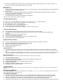
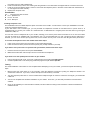
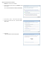
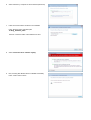
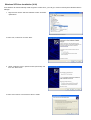
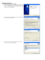
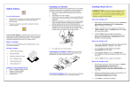
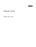
Quick Installation
Reference Card
Zling HCF Modem
PCI PnP Fax Modem
With Voice Speakerphone Functions
þ
þ
þ
þ
þ
þ
þ
Software Upgradeable
56,000* bps Data Modem (DUAL MODE) Supporting both V.92 and
V.90
14,400 bps Send & Receive Fax
Supports speeds up to 115,200 bps
Full Featured Voice Messaging
Speakerphone Functions
V.42 Error Correction and
V.42bis 4-to-1 Data Compression
Capable of receiving at up to 56kbps, and send at up to 31.2 kbps. Due to FCC regulations on power output, receiving speeds
limited to 53kbps. Actual speed vary. Requires compatible phone line and server equipment. Complies with both the v.90 56k
standard and K56Flex technology protocols
Version V1.1
If you have never installed an add-in board in your computer before, please follow the instructions in this section carefully. You
may also want to refer to the Installation Chapter in your manual.
What is V.92*?
l Modem on-hold
It allows you to take incoming call while you are online by putting the modem on hold. This feature requires a call waiting service
to be provided by your local phone company.
l Quick Connect
When the modem is dialing the repeated number, the “handshaking” time will greatly be reduced to less than 15 seconds.
Traditional V.90 modems would need more th an 20 seconds.
l Increased PCM upstream up to 48Kbps.
Faster upload speed means faster email attachment sending time.
* Require internet service provider to support V.92 protocol
Technical Specifications:
l
l
l
l
l
l
Data: ITU-T V.92/V.90, K56Flex, V.34, V.32bis, V.32, V.22bis, V.22, V.21, V.23, Bell 212A/103
Fax: ITU-T V.17, V.27ter, V.29, V.21 Channel 2, Group 3, EIA Class 1
Data Compression: ITU-T V.42 LAPM, MNP 5
Error Correction: ITU-T V.42 LAPM, MNP class 2-4
AT and extended AT command set compatible
H.324, V.80 for video conferencing over Internet and point to point connection
Fax/Voice Mail Features:
l
l
l
l
l
l
Automatically detects and routes incoming voice, fax, and data call to the proper module
Fax speed ups to 14,400bps·Sends and receives faxes to or from any group 3 fax machine, Printer-quality faxing,
forwarding
Schedules fax transmission and multiple recipients
Convenient voice storage and playback
Easy voice message retrieval through sound card, or from remote locations
Password protection for up to 999 mail boxes
Speaker Phone Features:
l
l
l
l
l
Turns your computer into a full-functioned speaker phone (active speakers and microphone required)
Places and answers telephone calls directly from your computer
Features mute, redial, hold, pause and clear functions
Phonebook with speed dialing access
Software volume control
Safety Precautions
1.
2.
3.
Turn OFF the computer before you begin. Also, turn OFF any external devices that are connected to your computer, such as printers.
Handle the board gently by the edges. Some of the component leads under the board have very sharp edges and may cause serious
injury.
To prevent electrostatic discharge damage to the components on your modem, do not remove the modem from the static-shielded bag
until you have discharged any static electricity from your body by touching any unpainted surface on the case of your computer.
Necessary Equipment
Make sure that you have all necessary equipment at hand before you begin. You should have:
l
l
l
l
l
l
l
The Z-Cyber Zling HCF Board
A Pentium III - 300 or faster compatible computer with an available PCI expansion slot
A modular telephone outlet and cable
A small, flat-blade screwdriver and a small pair of pliers or tweezers
A telephone set (Optional)
Shielded PC speakers or headset (required for speaker phone)
Microphone (required for speaker phone)
Installation Steps
The steps to install your modem are shown in order in this section. For some steps, you may need to refer to your computer’s User’s
Manual.
Selecting the COM Port
The Z-Cyber Zling HCF is PnP and can use COM ports 1 to 4 and IRQ's 2, 3, 4, 5, 10, 11, 12 & 15. This is selected automatically. There
are no hardware jumpers or dip switches to set.
Inserting the Fax/Modem
1.
2.
3.
4.
5.
Turn off the power to the computer. Also, turn off any external devices that are attached, such as a printer and monitor.
Take out the mounting screws on the back of you computer. Refer to your computer manual if you cannot locate them.
Remove the computer cover. Refer to your computer manual if you cannot determine how to remove the cover.
Select an empty PCI slot. You may need to remove the metal slot cover first, using a small screwdriver.
Discharge any static electricity in your body by touching any bare metal surface on the chassis of the computer and remove
6.
7.
8.
the modem from the static-shielded bag.
Press the board firmly into the slot ensuring that the gold tabs on the fax/modem are aligned with the connectors in the slot.
Insert the screw and tighten slightly. Check to ensure that the telephone jacks in the back of the modem are unobstructed. If
so, then tighten the screw securely.
Replace the computer cover.
Connection:
JP1 — Internal sound card connector
l Pin 1 : Speaker Out
l Pin 2-3 : Ground
l Pin 4 : MIC Input
Installing Telephone Lines
The Fax/Modem has two modular telephone jacks on the back of the modem. You will need to connect your Fax/Modem to the wall
outlet via a modular telephone cord.
If your wall outlet is not a modular type, you can purchase an inexpensive converter at most electronics or phone stores. It is
suggested that you connect your modem to a "dedicated line". A dedicated line is a regular phone line that does not go through a
switchboard, PBX, etc.
You can also connect a telephone set to your modem, enabling you to use the phone when the modem is not in use. The modem
can also be used as an autodialer with your telephone set. It is recommended that you use a single line phone outlet (RJ11).
However, you can use a two-line (RJ14) phone line, but the modem will only work on the first line using the center pair of wires.
To connect the telephone lines to the modem follow these steps:
1.
2.
Insert one end of the phone line into the jack on the modem labeled Line.
Insert the other end of the phone line into the phone jack, (usually located on your wall).
If you wish to use a phone set in conjunction with your modem, Please follow these steps:
1.
2.
Insert the line from the phone into the jack labeled Phone.
Make sure that the other end of the phone line is connected to the telephone.
If you wish to use the speakerphone function of your modem:
1.
2.
Using a microphone with a 1/8” mono plug, install the plug into the jack labeled Microphone.
Connect speakers with a 1/8” stereo plug, install the plug into the jack labeled Speaker.
Testing
The actual installation of the modem is now complete. Before attempting to use your modem, you should complete the following
steps:
1.
Before turning the power back on to the computer, check the telephone connection by lifting the telephone handset. You
should hear a dial tone. If you don’t, check that all phone cords are firmly connected.
2.
Turn the computer power back on. Lift the handset of the telephone again to check for a dial tone. Once again, you should hear
a dial tone.
3.
You’ve now completed the hardware installation of your modem. From here, you are ready to install the communications
software.
4.
Once you’ve installed your communications software, test the modem according to the instructions in either the hardware or
software manual.
Windows Vista (32-bit) driver Installation
1.
REMOVE any CD driver from the CDROM
2.
Windows Vista automatically detects a new MODEM is inserted
into the system.
Select “Locate and install driver software (recommended)”
3.
Click “Continue”
button in “User Account Control” window
4.
Windows want to search driver online,
search online”
please select “Don’t
5. Please select
“I don’t have the disc. Show me other options”
6.
Select “Browse my computer for driver software (advanced)
7.
Insert the Communication CD driver in the CDROM
Press “Browse” button and select path
“d:\Zling_HCF\Vista_32bit”
where d: is the driver letter of the CD/DVD rom drive
8.
Select “Install this driver software anyway”
9.
Now, the Zling HCF Modem driver is installed successfully.
Press “Close” button to finish
Windows XP Driver Installation (V.90)
Since Windows XP will automatically install the generic modem driver, you must go to Control Panel>System>Hardware>Device
Manager.
1. Right click the “Generic 56k HCF Data/Fax modem” and select
update driver
2. Select “No, not this time” and click “Next”
3. Select “Install from a list or specific location (Advanced)” and
then click “Next” button
4. Select “Don’t search. I will choose the driver to install”
5.
You will find the generic driver on the list. Click “Have Disk…”
to find the driver from the CD-ROM. Then click “Next” button
6.
Click “Browse”. Search driver from your CD-ROM drive and
select D:\Zling_HCF\V.90\Win2K_XP to open the
“cxt1056k.INF” file. (Note: Replace D: with the drive letter of
your CD-ROM drive if necessary.)
7.
Select “Z-Cyber Zling HCF Modem” and click “Next”. Then,
click “Continue Anyway” to install.
8.
Click “Finish” to complete the installation, and click “Yes” to
restart your computer.
Windows 95 / 98 / 98SE / ME / 2000 / XP 64-bit / Vista 64-bit Driver Installation
All steps are much easier than Windows XP Driver Installation.
computer detects a new hardware:
Choose specific locations for the drivers as follows once your
For V.90
Windows 95 / 98/98SE
Windows ME
Windows 2000/XP (32-bit)
Windows XP (64-bit)
Vista (32-bit)
Vista (64-bit)
D:\Zling_HCF \V.90\Win95_98
D:\Zling_HCF \V.90\Win_Me
D:\Zling_HCF \V.90\Win2k_XP
D:\Zling_HCF \V.90\XP_64bit
D:\Zling_HCF \V.90\Vista_32bit
D:\Zling_HCF \V.90\Vista_64bit
(Note: Replace D: with the drive letter of your CD-ROM drive if necessary.)
NetWaiting Installation
(Call Waiting feature only works under V.92)
1. Search CD-ROM from your CD-ROM drive and select D:\
Zling_HCF \Netwaiting1.05 (Note: Replace D: with the drive
letter of your CD-ROM drive if necessary.). Run the
“Setup.exe” to start the installation.
2.
Click “Yes” for License Agreement. Under “Choose Destination
Location”, click “Next” to continue.
3.
Click “Next” button under “Select Program Folder”, and then
click “Finish” to complete the installation.
Common Problems and Their Solutions
Problem: Modem answers incoming calls and then returns to the on-hook condition, disconnecting the caller.
This occurs most often when connecting to a UNIX system. In most case, the host does not prefer to see any result or command echo
codes. If this is the case, the codes can be disabled by adding E0 Q1 to the modem configuration string.
Problem: No echo from modem
This is normally caused by an I/O address or IRQ conflict.
necessary use another COM Port or I/O address setting.
Verify that the COM Port is not in use by any other serial device and if
Problem: The modem dials and appears to complete the connection, but the communications software does not enter the correct
mode. (The screen remains blank.) There may be an I/O conflict (See the solution for the previous problem, "No echo from modem").
The Result Codes may have been disabled by the software configuration set up.
If so, change it to Q0.
Check if Q1 is in the configuration or initialization string.
Your software may require numeric result codes rather than verbal result codes. Use either V0
for numeric result codes or V1 for verbal result codes in your initialization or configuration string. Some software require full extended result
codes (ie. CONNECT 33600 instead of CONNECT). This can be controlled by the Xn command. X0 sends a summarized code
(CONNECT) and X4 sends a full extended code (CONNECT 33600).
Problem: The modem does not auto answer.
The auto answer mode is determined by the S0 register. If S0 has been set to 0, the modem will not answer. Assign another value to S0
by entering the following command S0=n, where n=the number of rings to occur before the call is answered (ATS0=2, the modem answers
after two rings).
Problem: The modem always answers the phone
Set the S0 register to 0. ATS0=0
Problem: The communications software displays, "No Dialtone".
Make sure that your phone cable is working properly and that it is firmly seated to the phone socket at your phone jack and in the rear
panel of the modem.
Problem: A high pitched squeal is emitted from the external speakers..
This phenomenon is “feedback” and occurs when the microphone is pointed at the external speaker or is close enough to pick up the
speaker output. This may be remedied by using a unidirectional microphone, making sure that it is pointed away and as far from the
speaker as functionally possible. Another option is to use a headset with an attached microphone.
On-line Technical Support
If you have access to the World Wide Web be sure to visit the Z-Cyber home page at:
http://www.z-cyber.net/support