1
OPERATOR'S
MANUAL
II:RRFTSMRN'I
PLUNGE ROUTER
DOUBLE INSULATED
Model No.
315.175170
_k
WARNING: To reduce the dsk of in._u_,
the user must read and understand the
operator's manual before using this product.
Customer
Help Line: 1-B00-932-3188
Sears, Roebuck and Co., 3333 Beverly Rd., Hoffman Estates, IL 60179 USA
Visit the Craftsman web page: www.seara.com/craftsman
983000-497
6-9-06 [REV:02)
Save this manual
for future
reference
• Warranty ..........................................................................................................................................................................
2
•
2
Introduction .....................................................................................................................................................................
• General Safety Rules....................................................................................................................................................
• Specific Safety Rules......................................................................
3-4
:................................................................................
• Symbols........................................................................................................................................................................
4
5-6
• Electrical ..........................................................................................................................................................................
7
• Features........................................................................................................................................................................
8-9
• Assembly.......................................................................................................................................................................
10
• Operation ..................................................................................................................................................................
11-21
•
Maintenance .............................................................................................................................................................
22-23
•
Exploded Viewand Parts List...................................................................................................................................
•
Parts OrdednoJServica.....................................................................................................................................
24-25
Back Page
ONE YEAR FULL WARRANTY ON CRAFTSMAN TOOL
If this Craftsman tool fails to give complete satisfaction w(thin one year from date of purchase, RETURN IT TO THE
NEAREST SEARS STORE OR SEARS PARTS & REPAIR CENTER IN THE UNITED STATES, and Sears will repair it,
free of charge.
If this Craftsman too( is used for commemla] or rental purposes, this warranty applies for only 90 days from the date of
purchase.
This warranty gives you spec(f(c legal rights, and you may also have other rightswhich vary from state to state.
Sears, Roebuck and Co., Dept. 817WA, Hoffman.Estates, IL 60179
This tool has many features for making its use more pleasant and enjoyable. Safety, performance, and dependability
have been given top priority in the design of this product making it easy to maintain and operate.
A
=m, WARNING: Read and understand all instructions.
Failure to follow all instructionslisted below, may
result in electric shock, fire and/or serious personal
injury.
•
Avoid occidental starting, Be sure switch Is off before
plugging in. Carryingtools w(th yourfinger on the switch
or ptuggingin toolsthat have the switchon invites
acckients.
•
Remove adjusting keys or wrenches before turning
the tool on. A wrench or a kay that is left attached to a
rotatingpart of the toot may result in personal injury.
Do not oveweach. Keep proper footing and balance
at all _
Proper footing and betanca enables better
control of the tool (nunexpected s(tuat(ons.
Usa safety equipment. Always wear eye pretection.
Dust mask, nonskidsafety shoes, hard hat, or hearing
protection must be used for appropriate conditions.
Do not wasr loose clothing or Jewelry. Contain long
hair. Loose clothes,jewelry, or long hair can be drawn
into air vents.
SAVE THESE INSTRUCTIONS
WORK AREA
•
• Keep your work area clean and well IlL Cluttered
benches and dark areas invite accidents.
•
• Do not operate power fools in explosive
atmosphere_ such as in the pre_)nce of flammable
liquids, gases, or dust. Power tools create sparks
which may ignite the dust or fumes.
•
• Keep bystander_ children, and visitors awaywhile
operating a power tooL Distractionscan cause you to
lose control.
ELECTRICAL
•
SAFETY
• Double insulated tools are equipped with a
polarized plug (one blade is wider than the other).
This plug will fit In a palarlzed outlet only one way,
If the plug does not fit fully in the outlet, reverse
the plug. If It still does not fi_ cord_acte qusiitied
alactflcla_ to install a polarized outlet. Do not
change the plug in any way. Double insulation[]
eliminates the need for the three-wire grounded power
cord and grounded power supply system.
Do not usa on a ladder or unstable support. Stable
footing on a solid surface enables better control of the
tool in unexpected situations.
"FOOL USE AND CARE
•
•
•
• Avoid body contact with grounded surfaces such as
pipes, radiators, ranges, and refdgeratom. There isan
increased risk of electricshock if your body is grounded.
• Don't expose power tools to rein or wet condltlo,s.
Water entering a power tool will increase the risk of
electric shook.
•
• Do not abuse the cord. Never use the cord to carry
the tools or pull the plug Item an outlet. Keep cord
away from heat, o11,sharp edge_ or moving parts.
Replace damaged cords Iremedletaly. Damaged
cords increase the n'skof etactdc shock.
•
• When operating a power tool outside, use an outdoor
exlen(don cord marked 'q/+f.A"or _1". These cords
are rated for outdoor use and reducethe rlsk of electdc
shock,
•
Maintain tools with care. Keep cuffing tools sharp
and ck_an. Properly maintained tools with sharp
cutting edges are less likelyto bind and are eesiar to
contto(.
•
Check for mlssiIgnment or binding of moving parts,
breakage of parts, and any other condition that
may affect the tool's operation. If damaged, have
the toot serviced be_ra using. Many accldems are
caused by poorlymaintained tools.
•
Usa onlyaccaesodee that are recommended bythe
manufacturer for your model. Accessodes that may
be suitable for one tool, may become hazardouswhen
used on another tool.
•
Keep the tool and Its handle dry, clean and free
horn _l and grease. Always use • clean cloth when
cleaning. Never use brake fluids, gasoline, petroleumbased products, or any strong solvents to clean your
tool. Following this rulewill reduce the dsl( of loss of
control and deteriorationof the enclosure plastic.
PE RSONAL SAFETY
• Stay alert, watch what you are doing and use
common seuss when operating a power tool. Do
not use tool while tired or under the influence
of drugs, alcohol, or medfcaflon. A moment of
inattention while operating power tools may result in
sar(ouspersona( (n(u_,
• Dress properly. Do not wesr loose clothing or
jewelry. Contain long hair. Keep your heir, clothfng,
and gloves away from movlug parts. Loose clothes,
jewelry, or long hair can be caught In moving parts.
3
Use clamps or other practical way to secure and
support the workpiece to a stable platform. Holding
the work by hand or against your body is unstable and
may lead to loss of control.
Do not force tool. Usa the correct tool for your
application. The correct tool will do the job better and
safer at the rate for which R is designed.
Do not use tool if awltch does not turn it on or off.
Any tool that cannotbe controlled with the switch Ls
dangerous and must be repaired.
Disconnect the plug from power source before
making any adjustments, changing accessories,
or storing the tool. Such preventive safety meesui_s
reduce the Askof starting the tool accidentally.
Store idle tools out of the reach of children and
other untrained persomk Tools are dangerous in the
hands of untrained users.
SERVICE
• When servicing a tool, use only Identical
replacement parts. Fottow instructions(n the
Maintenance section of this manual. Use of
unauthodzed parts or failure to follow Maintenance
Instructions may create a risk of electric shock or
injur/.
• Tool service must be performed only by qualified
repair personnel, Service or maintenance performed
by unqualified personnel could result in a risk of injury.
•
Sits coast after router has been tomed off.
•
Hold tool by Insulated gripping surfaces when
performing an opemtlon where the cutting tool
may contact hidden wlrlng or Its own cord. Contact
with a "live" wire will make exposed metal parts of the
cutting tool "live" and shook the operator.
•
Know your power tool. Read operators manual
corefu#y. Learn its appScatJons and Iknn_tations,a_
well as the speoWJopotential hazards related to this
tooL Fo)lowlng Lhisrule will reduce the risk o_electric
shock, fire, or serious injury.
• Check damaged parts. Before further use of the
toot, a guard or other part that Is damaged should
be carefully checked to determine that it will
opereto prope_j and perform its Intended tonctlen.
Check for alignment of moving parts, binding of
moving parts, breakage of parts, mounting, and
any other conditions _at may affect its operation.
A guard or outer part that Is damaged should be
properly repaired or replaced by an authorized
service center. Following this mrs wit_reduce the risk
of shock, fire, or serious injury.
• Make sure your extension cord Is In good condition.
When using an extension cord, be sure to use one
heavy enough to carry the current your product
will draw. A wire gauge size (A.W.G,) of at least
14 is recommended for an extension cord 50 feet
or less In length.
A cord exceeding 50 feet b not
recommended. If In doubt, use the next heavier
gangs. The smaller the gauge number, the heavier
the cord. An undersized cord will cause a drop in line
voltage resulting In loss of power and overheating.
• Inspect for and remove all nails from lumber before
using this tool. Following this rule will reduce the dsk
of serious personal injury.
• Save those Instruciform. Refer to them frequently
and use them to instruct others who may use this
tool. If you loan someone this tool, loan them these
instructionsalso.
• Always wear safety glasses. Everyday eyeglasses
have only Impact-resistant lenses; they are NOT
safety g_a6ses. Following this rulewill redoce the r_sk
of serious personal injury.
• Protect your lungs. Wear s Pace or dust mask if the
operation is dusty. FoX,wing this rusewil_reduce the
risk of serious personal iniury.
• Protect your hearing. Wear hearing protection
during extended periods of operation. Fo_lowingthis
rule will reduce the risk of serious personal injury.
• Inspect tool cords periodically end, if damaged,
have repaired at your nearest Sears or other
qualJf'_d service center. Constantly stay aware of
cord Iocalden. Following this ru_ewitl reduce the risk of
electric shock or fire.
_k
WARNING: Some dust created by power sanding, sawing, grinding, drilSng,and other construction activities
contains chemicals known to cause cancer, birth defects or other reproductive harm. Some examples of these
chemicals am:
• lead from lead-baaed paints,
• crystallinesilica from bricks and cement and other masonry products, and
• arsenic and chromium from chemically-treated lumber.
Your risk from these exposures varies, depending on how often you do this type of work. To reduce your exposure
to these chemicals:work in a well ventilated area, and work with approved safety equipment, such as those dust
masks that are specialtydesigned to filter out microscopic particles.
4
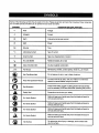
Someofthefollowing
symbols
maybeusedonthistool Please
studythemandlearntheirmeaning.
Properinterpretationofthesesymbols
willallowyouto operate
thetoolbetterandsafer.
SYMBOL
NAME
DESIGNATION/EXPLANATION
V
Volts
Voltage
A
Amperes
Current
Hz
Hertz
Frequency (cycles per second)
W
Watt
Power
min
Minutes
Time
"_
Alternating Current
Type of current
,=
Direct Current
Type or a characteristic of current
no
No Load Speed
Rotatlonatspeed, at no load
[]
Class II Construction
Double-insulated construction
.../rain
Per Minute •
Revolutions, strokes, surface speed, orbits etc., per minute
_)
Wet Conditions Alert
Do not
Read The Operator's Manual
operator's
manual
before
product.
To
reduce the
risk of
injury,using
user this
must
read and understand
Eye
A
_)
Protection
expose
to rain or use In damp locations.
Always
safetygoggles
safety glasseswith
side shields
and, as wear
necessary,a
full faceorshieldwhen
operatingthis
product.
Safety Alert
Precautions that involve your
No Hands Symbol
serious
personal
Injury.
Failureto
keep your
hands away from the blade will result in
No Hands Symbol
Failure to keep your hands away from the blade will result in
serious personal injury.
No Hands Symbol
Failure
keep your
hands away from the blade will result in
seriousto
personal
injury.
No Hands Symbol
Failure to keep your hands away from the blade will result in
serious personal Injury.
Hot Surface
To
the risk of injuryor damage, avoid contact with
anyreduce
hot surface.
5
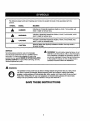
safety.
Thefollowing
signal words and meanings are Intended to explain the levels of risk associated with this
product.
SYMBOL
SIGNAL
MEANING
DANGER:
Indicates an imminently hazardous situation, which, If not avoided, will
result in death or serious injury.
WARNING:
Indicates a potentially hazardous situation, which, if not avoided, could
result in death or serious injury.
CAUTION:
Indicates a potentially hazardous situation, which, if not avoided, may
resultin minor or moderate injury.
CAUTION:
(WithoutSafety Alert Symbol) Indicates a situation that may result in
property damage.
SERVICE
A
Servicing requires extreme care and knowledge
and should be performed only by a qualified service
technician. For service we suggestyou return the
product to your nearest SEARS OR OTHER QUALIFIED
SERVICE CENTER for repair. When servicing, use only
identical replacement parts.
&
WARNING: To avoid serious personal injury, do not
attempt to use this product until you read thoroughly
and understand completely the operator's manual. If
you do not understand the warnings and instructions
in the operators manual, do not use this product.
Call Sears customer service for assistance.
WARNING:
The operation of any power tool can result in foreignobjects being thrown into your eyes, which
can resuit in severe eye damage. Before beglnn)ng power tool operation, a_wayswear safety
goggles or safety glasses with side shields and, when needed, a full face shield. We recommend
Wide Vision Safety Mask for use over eyeglasses or standard safety glasses with side shields.
Always use eye protection which is marked to comply with ANSI Z87.1.
SAVE THESE INSTRUCTIONS
6
DOUBLEINSULATION
Doubleinsulation is a concept in safety in electric
power
tools, which eliminates the need for the usual three-wire
grounded power cord. A)I exposed metal parts are
isolated from the internal metal motor components with
protecting insulation. Double insulated tools do not need
to be grounded.
_.
WARNING: The double insulated system is
intended to protect the user from shock resulting
from a break in the tool's internal insulation.Observe
all normal safety precautionsto avoid electdcal
shock.
NOTE: Servicing of a tool with double insulationrequires
extreme care and knowledge of the system and should
be performed only by e qualified service technician. For
service, we suggest you return the toot to your nearest
Sears or other qualified service center for repair. Always
usa odginal factory replacement parts when servicing.
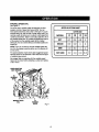
ELECTRICAL
EXTENSION
When using a power tool at e considerable distance from
a power source, be sure to use an extensioncord that has
the capacity to handle the current the tool will draw. An
undersizedcord will cause a drop in line voltage, resulting
in overheating and loss of power. Use the chart to
determine the minimum wire size required in an extension
cord. Only roundJacketed cords listed by Underwnter's
Laboratories(UL) should be used.
When working outdoors with a too(, use an extension
cord that is designed for outside use. This type of cord is
designated with "WA" on the cord'sjacket.
Before using any extension cord, inspect it for !oose or
exposed wires and cut or worn insulation.
-Ampamrating(ontoo]fimepJate}
0-2.0 2.1-3.4 3.5-5.0
Cord Length
5.t-7.0
7.1-12.0
12.1-16.0
Wire Size {A,W.G.)
25'
16
16
16
16
t4
14
50'
16
16
16
14
14
12
100'
16
16
14
12
10
--
CONNECTION
This tool has a preo{slon-bu(It electr{o motor. It should be
connected to a power supply that is 120 volts, 60 Hz,
AC only {normal household current). Do not operate
this tool on direct current (DC). A substantial vo}tage drop
will cause a loss of power and the motor will overheat. If
your tool does not operate when plugged into an outlet,
double-check the power supply.
CORDS
**Us_ on 12gauge. 20 amp ¢Jrcult
NOTE:AWQ_ AmericanWire Gauge
_1= WARNING: Keep the extension cord clear of the
working area.. Positionthe cord so that it will not get
caught on lumber, tools or other obstructionswhile
you are working with a power tool. Failure to do so
can resultin serious personal injury.
_
WARNING:
Check extension cords b_fore each
use. If damaged replace immediately. Never use tool
with a damaged cord since touching the damaged
area could cause electrical shock resulting in serious
injury.
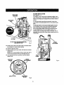
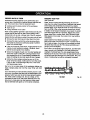
PRODUCTSPECIFICATIONS
PlungeDepth
............................................................
0-2 in.
Ge])et...................................................... 1/4 in. and 1/2 in.
Adaptor.....................................................................
No Load Speed ................................... t5,000-25,000(min.
Input .............................. 120 '4, 60 Hz, AC only, 10.0 Amps
Net Weight ............................................................... 8.5 Ibs.
114 In.
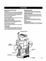
FRONTVIEWOFROUTER
VARf,
A6LE
SPEEDDIAL
SPEEDSELECTION
81GHTWINDOW
DIGITALDEPTH
READOUT
PLUNGE
DEPTHKNOB
.\
OI',)/OFF
SWITCH
DEPTHSTOP
LOCKKNOB
HANDLE
DEPTH
STOPKNOB
STOPBAR
1.
DUSTSHIELD
SPINDLELOCK
DUSTCONTROL
ADAPTOR
1/4 In. ADAPTDR
Fig. 1
8
KNOWYOURPLUNGEROUTER
ERGONOMIC DESIGN
The design of this tool provides easy handlingwhen
operating in different positionsand at differentangles.
gee Figures f - 2.
The safe use of this product requ#as an understanding of
the Information on the tool and in this operator's manual
as well as a knowledge of the project you are attempting,
Before use of this product, familiarize yourself with all
operating features and safety rules.
PLUNGE LOCK LEVER
Your muter has a _rungelock lever that allows for free
plunging.This feature is very useful for table mounted
operations on UL listed muter tables when used with the
plunge depth knob.
DEPTH STOP KNOB
The depth stop knob worl<swith the stop bar for accurate
depth of plunge when muting.
SPINDLE LOCK
A spindle look secures the spindle so that only one
wrench is needed to toossn the collar nut and change
cutters.
DIGITAL DEPTH READOUT
Easilyview your depth of cut adjustments using the
digital depth readout which shows changes of depth in
increments of 1/64 in. and 1110 mm.
VARIABLE
SPEED
The variable speed dial allows the router to develop a no
load speed that can be adjusted from 15,000 to 25,000/mln.
DUST CONTROL ADAPTOR
The dust control adaptor attaches to the router base for
dust-free muting.
DUST SHIELD
A clear p}astic dust shield is installedon the front of the
muter for protection against flying dust and chips. The
shield is designed to fit the opening of the muter base.
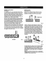
REARVIEWOFROUTER
PLUNGE
DUSTCHUTE
COLLETI_
ROUTERBASE
BUBBASE
9
Fig. 2
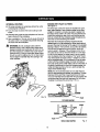
UNPACKING
This product has been shipped comprately assembled.
INSTALLING DIGITAL DEPTH READOUT
See Figures 3.
BATTERY
• Carefully remove the tool and any accessoriesfrom the
box. Make sure that all items listed in the packing list
are included.
= Unplug the router.
• Inspect the tool carefully to make sure no breakage or
damage occurred dudng shfpping,
• Replace the battery cover end secure with screw.
•
•
Remove screw from the battery cover.
Insert the 3V battery provided with the tool.
• Do not discard the packing matadal until you have
carefully inspected and satisfactorily operated the tool
• If any parts ere damaged or missing, please cell
1-800-932-3188 for assistance.
PACKING
LIST
Plunge Router
Dust Control Adaptor
Collar
Plunge Depth Knob Assembly
Screws (2)
1/4 in. Adaptor
3V Battery
15/16 in. Wrench
Operator's Manual
_1= WARNING: If any parts are damaged or missing
do not operate this tool until the parts are replaced,
Failure to heed this warning could resultIn serious
personal injury.
i
_l=
A
A
SCREW
BATI'ERYCOVER
BATI'ERY
Fig. 3
WARNING: Do not attempt to modify this tool
or create accessories not recommended for use
with this tool, Any such alterationor modification is
misuse and could result in a hazardous condition
leading to possible sadous personal injury,
WARNING: Do not connect to power supply unttl
assembly is complete. Failureto comply could result
in accidental starting and possiblesedous Injury,
10
_"
WARNING:
Do not allOWfamiliaritywith tools
•
NOTE: When using the spindle lock button for any
application, make sure the button goes aHthe way in.
If the button is depressed and does not go all the way
In, turn the collet until the spindle lock button locks Into
place.
to make you careless. Remember that a careless
fraction of a second is sufficient to inflictserious
inlury.
• k WARNING: Always wear eafsty goggles or safety
glasses with slde shields when operating power
tools. Failureto do so could resultin objects being
thrown into your eyes resulting in possible serious
injury.
_
WARNING, Do not use any attachments or
aecessodea not recommended by the manufacturer
of this tool. The use of attachments or accessories
not recommended can result in serious personal
in}ury.
• Place the wrench provided through front of router base
onto cetlet nut and turn counterclockwiseto loosen.
WARNING: If you are changing a cutter
immediately after use, be careful not to touch the
cutter or toilet with your hands or fingers. They will
get burned because of heat buildup from cutting.
Always use the wrench provided.
• Install cutter once collet nut is loose. If changing
cutters, cutter will easily slip from colfet after loosening
cotter nut.
_1= WARNING: Keep a finn grip on router with both
hands at all times. Failureto do so could result in
loss of control feeding to possible serious personal
injury.
NOTE: The collet is machined to precision tolerances
to fit cutters with 1/2 in. diameter shanks.To use
cutters with 1/4 in. diameter shanks, insert the 1/4 in.
adaptor into the 1/2 in. collar.
• Insert shank (non-cuttingend) of cutter until shank
bottoms out, then pull it out 1/16 in. to allow for
expansionwhen the cutter gets hoL
• Tfghten the toilet nut securely by turning clockwise
with the wrench.
APPLICATIONS
You may"use this tool for the purposes listed below:
• Routing grooves, shaping edges, freehand designs,
etc., In wood
• Chamfering, rabbeting, dadoing, and dovetailing in
wood
•
_lh
Depress spindle lock.
• Release spindle lock,
Routing edges on ]amlnatas
• Replaoe chip shield.
WARNING: Before performing any adjustment,
make sure the tool is unplugged from the power
supply and the switch Is in the OFF position.Failure
to heed this warning could result in sedous personal
injury.
_1= WARNING:
Bit continues to rotate after the router
SPINDLE
LOCK
has been turned off. To avoid injury, wait until the bit
has come to a complete stop before removing router
from the workplace.
CAUTION" To prevent damage to the spindle
or spindle lock, always allow motor to come to a
complete stop before engaging the spindle lock.
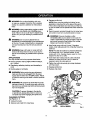
CHANGING CuI"rERS
See Figures 4 - 5.
• Unplug the router.
• Remove dust shield from router base.
CUTTER
11
15/18Ja,WRENCH
Fig. 4
COLLET
NUT
TO ADJUST DEPTH OF CUT
See Figures 6 - 8.
• Unplug the muter.
COLLET
NUT
. COLLET
•Ra]se cutter by un]ockingplunge lock lever.
• Adjust hex nuts on threaded post until cutteris inside
router subbase.
•
Piece router on a fiat surface,
• Lower muter until tip of cutter barely touches fiat
surface.
• Lock plunge lock lever to position cutter at zero depth
of cuL
CUTT'ER
Wffff "If4b.
SHANKDIAMETER
_k
• Adjust he>(nuts until they come in contact with stop
flange, This will provide a posit_onstop at zero dap_.hof
cut,
1/'4In.ADAPTOR
Fig. 5
• Make sure the hex nuts are securelytightened against
each other.
WARNING: Ifthe co|In Is not s_mty tig_ened,
the cutter may detach dudng use causing serious
personal injury.
_1= WARNING:
Do not use cutters with undersized
shanl_s.Undersized shanks will not tighten properly
and could be thrown from the tool causing serious
personal Injury.
_k
TO LOCK
WARNING: Do not use cutters that are targer in
diameter than the opening in muter base. Use of
such cutters will come in contact with the muter
base and damage both the cutter and the muter
base. This situation could also cause possibleloss
of control or create other hazardous conditions that
could cause possible serious personal injury.
TOUNLOCK
PLUNGE
LOCKLEVER
SELECTING DEPTH OF CUT
Proper depth of out depends on several factom: the
horsepower of the muter motor, the type of cutter,and
the type of wood. A lighlweight, low horsepower muter
is designed for making shallow cuts; a muter with higher
horsepower is dsslgned for deeper cuts. Smafl gutters,
such as veiningcutters with 1/16 in. gutting diameters,
are designed to remove only small amounts of wood.
Large cutters, such as straight-flute cutters, remove larger
amounts of wood and make deeper cuts in soft woods,
such as white pine,
INSIDESUBBASE
Fig. 6
•
Rotate depth stop lock knob counterclockwiseto
unlock depth stop knob.
• Rotate depth stop knob until stop bar touches muter
base,
• Turn on digital depth readout by pushing on/off/zero
button. Push the mm/ln button for desired unitof
Choose a depth of cut that will not place excessive strain
on the muter motor. If you need extra tome or the motor
speed slows down considerably,turn off the router and
reduce the depth of cut. Then make the cut In two or more
passes.
When muting a groove that is too deep to safely cut in
one pass, make the cut in several passes. We recommend
that cuts be made at a depth not exceeding lIB In. and
that several passes be made to reach deeper cuts.
mQasure.
NOTE: Push the backllght button to illuminate the
digital depth readout..
• Rotate depth stop knob to position stop bar at desired
depth of cut.
• Turn depth stop lock knob clockwise to lock stop bar
In place.
12
PLUNGE DEPTH KNOB
See Figures 9.10.
DEPTHSTOP
LOCKKNOB
The weight of the router plus the awkward position It is in
when mounted to a router table make {tve_ difficultto set
depth of cut simply by turning t_e hex nut with a 15116 in.
wrench.
DEPTHSTOP
KNOB
It is recommended using the plunge depth knob when
your muter is mounted upside down on a UL listed muter
table.
The plunge depth knob Is spring loaded against the hex
nut to prevent router motor from accidently separating
from router base, If plunge depth knob is turned too
far up plunge depth shaft, the spdng wi))cause the rod
to pop off before hex nut. Do not remove hex nut. It
should remain on plunge depth shaft at all times. This is
especially important when using router upside down on a
router table.
TIP OFCUTI'ERTOUCHINGWORKPIECE
=
ZF.,RO
DEPTHOFCUT
PLUNGE
0EPT.
Fig, 7
• Pos]tion the router so that the cutter can extend below
the subbase for desired depth setting.
•
•
Unlock plunge lock lever.
Grasp handles and lower router untilstop bar contacts
router base.
NOTE: Do not use excessive force to touch slop bar to
router base. Excess{ve force can damage stop bar.
• Lock plunge lock lever to position cutter at desired
depth of cut,
BACKLIGHT
BUTTON
mm/In. BUTt'ON
FLANGE
DIGITAL
DEPTHREADOUT
ON/OFF/ZERO
BUR'ON
Fig. 9
Fig. 8
13
TO INSTALL PLUNGE DEPTH KNOB
• Unplug the router.
• Remove upper hex nut from plunge depth shaft.
NOTE: This is the only time you should remove the
hex nut from the muter. Also, if you remove the plunge
depth knob for any reason, you must reinstattthe hex
nut before reusing the router.
•
Turn remaining hex nut counterclockwiseuntil 1/4 in.
of thread is remaining at the top of the plunge depth
shalL
• Place compression springon top of bex nut.
• Place plunge depth knob on top of compression spdng
and a|i0n tabs on knob with flats on hex nut.
• Compress spring by carefully pushing down on top of
plunge depth knob,
• Thread plunge depth knob clockwise onto plunge
depth shaft.
WARNING: Replacing plunge depth knob without
compression sprtn0 could result in plunge depth
knob and hex nut vibrating off plunge depth shaft.
This situation coutd cause motor to separate from
router base, resulting in possible serious personal
injury,
TO ADJUST DEPTH OF CUT USING PLUNGE
DEPTH KNOB
• Unplug the router.
• Rotate depth stop lock knob counterclockwiseto
unlock depth stop knob.
• Rotate depth stop knob to raise stop bar.
• Unlock plunge look lever and raise cutter to {ts
uppermost posft[on.
• Plunge router until cutter reaches theapproximate
desired depth of cut.
• Lock plunge lock lever,ternporer[ry looking cutter at
desired depth of cut.
•
Turn plunge depth knob c{ockw(seuntil box nut s(ts
against stop flange. Do not overtkJhten.
• Unlock plungelock lever.A]waysunlockplunge lock
lever beforesetting depth of cut with plungedepth knob.
• Turn plunge depth knob until cutter reaches desired
decth of cut.
• Lock plunge lever.Always lock cutter in place before
muting.
• Rotate depth stop lock knob counterclockwiseto
unlock depth stop knob,
• Rotate depth stop knob until stop bar touches router
base.
• Tighten depth stop lock knob securely.
PLUNGEDEPTHKNOB
SPRING
:OMPRESSION
HEXN%_
STOPFLANGE
PLUNGE
DEPTHSHAFT
PLUNGELOCKLEVER
Fig. 10
14
VARIABLESPEEDDIAL
See Ftgure 1!.
The router has e variable speed dial designed to allow
operator control of speed and torque IIraits, You can
make speed selections best suited to the type of cut, the
material being cut, and the size of cutter being used. The
variable speed dial allows you to adjust router speed from
15,000 to 25,000/rain. There is a six-step scale CAto F/on
the variable speed diei. To increase the speed and torque
of the router, turn the vadable speed dial to a higher
setting (F). Turn to a lower setting to decrease speed and
torque (A).
SPEEDSELECTIONCHART
CUTrER SIZE
MATERIAL
NOTE; If you do not want to use the vadable speed dieT,
turn it to the highest possible setting, and the feature w[U
not be active.
The speed selection chart shown gives suggested speed
settings based on the diaraeter of the cutter and the type
of material being routed.
We suggest that you practice wfth the variable speed
feature of the router before Installing a cutter and making
cuts in wood.
SPEEDSELECTION
SIGHTWINDOW
TO
DECREASE
SPEED
\
VARIABLE
_PEED
DIAL
TO
INCREASE
SPEED
Fig, 11
15
1/4
3/8
1/2
3/4
SOFT
E-F'
O-E
A-B
A
MEDIUM
D-E
C-D
A
A
HARD
C-D
B-C
A
A
VERYHARD
D-E
C-D
C-D
B-C
TURNING THE ROUTER
See F_jure !2.
ON/OFF
USING DUST CONTROL ADAPTOR
See Figure13.
To turn router ON, push switch to the ON (I) position.To
turn router OFF, push switch to the OFF (O) posft_on.
CAUTION: Practice with the router before installing
a cutter and making cuts in wood.
The dust control adaptor is used wlth the dust chute and e
vacuum hose for dust-free routing.
To installthe dust control adaptor:
• Remove the dust shJeJdand dust chute.
•
Locate the two screw holes in the adaptor. One screw
hole will have a pin hole next to it.
• Align the screw ho(e and pin hole of the adaptor with
the screw honeand pin on the router base. Push into
place.
ON/OFFSw]'rCH
• Insert screws provided into each hole and screw into
place.
• Replace dust shield and dust chute.
For dust-free routing, attach a vacuum hose to dust chute.
Turn vacuum on and begin routingoperation.
SCREW_
Fig. 12
BO'I'I'OMVIEW
DUSTCONTROL
ADAPTOR
PiN HOLE
16
Fig. 13
EDGE ROUTING
WARNING:Cutter
continues to rotate after the
router has been turned off. To avoid in{ury,wait until
the cutter has come to a complete stop before removing router from the workplace.
OPERATING THE ROUTER
See Figures 14- 16.
When routing straight cuts across stocK,clamp e straight
edge to the workpiece to use as a guide. Position the
straight edge parallel to the fine of cut and offset the
distance between the cutting edge of the CUtterand the
edge of the muter base. Hold the reuter base against the
straight edge and rout the groove.
•
Place the muter on the edge of the workpiece without
the cutter contacting the workpiece.
•
•
Turn muter on and let the motor build to full speed.
Graduallyfeed the cutter into the workplace.
•
Upon completion of the cut, turn the muter off and let
the cutter come to a complete stop besom removing
the reuter _om theworkpiece.
When muting s groovewider then the diameter of the cuttar, clamp a straight edge on both sides of the cut fines.
Position both guides parallel to the desired rlneof cut and
spaced equal distances from the desired edges of the
groove. Rout along one guide, then reverse direction and
rout along the other guide. Clean out any remainingwaste
in the center of the groove.
CLAMP
STRAIGHT
EDGE
WORt(PIECE
CUTTEREXTENDED
BELOWSOBBASE
Fig. 14
17
Fig. 15
INTERNALROUTING
• Tilt router and place on workpFecawithout the cutter
contacting the workplace.
• Turn the muter on and let the motor build up to full
speed.
• Gradually feed cutter into theworkplece until the subbase is level with the workplace.
•
A
Upon completion of the cut, turn the muter off and let
the cutter come to a complete stop before removing
the reut_from the wcrkpiece.
WARNING: Do not use large router cutter for
freehand routing. Use of large muter cutters when
freehand muting could cause loss of control or oreate other hazardous conditionsthat could result in
personal injury. If using a router table, large cutters
should be used for edging only. Do not use cutters
that are larger In diameter than the opening In the
router subbase.
EDGING WITH PILOT CUTTERS
See F/gum 17.
The arbor-type cutters with pilots ere excaJient for quick,
easy, edge shaping of any wo_plase edge that Is either
straight or curved at a curvature as great or greater than
the radius of the cutter to be used. The pilot prevents the
cutter from making too deep s cut; and holdingthe pilot
firmly in contact with the workplace edge throughout prevents the cut from becoming too shallow.
Whenever the workpiece thickness together with the
desired depth of cut (as adjusted by router depth setting)
are such that only the top part of the edge Is to be shaped
(leaving at leasta 1/16 inch thick uncut portion at bottom),
the pilot can dde against the uncutportion, which will
serve to guide it. However, if the workplace is too thin or
the cutter set too low so that there will be no uncut edge
toridethepilot
against,
an extnlboar_toactas e guide
must be ptacad under the workpieca. This "guide" board
must have exactly the same contour--straight or curved-as the workp'feceedge. if it is posR'=oned
so that its edge
Is flush with the workplace edge, the cutter will make a
full cut (in as far as the cutter radius).On the other hand, if
the guide is positionedout from the workplace edge, the
cutter will make less than a full cut--which w_;Ialter the
shape of the finished edge.
NOTE: Any of the piloted cutters can be used without a
pilot for edge shapingwith guides, as preceding. The size
(diameter) of the pilot that is used determines the maximum cut wldth that can be made with the prrotagainst the
workpiece edge (the small pilot exposes all of the cutter;,
the large one reduces this amount by IJ16in.).
WORK
ROUTER
PILOT
TOPEDGESHAPING
PILOT
WHOLEEDGESHAPING
18
Fig.17
DIRECTIONOFFEED
AND THRUST
See Ftgures 18- !9.
The muter motor and cutter revolvein a clockwise direction. This gives the tool a alight tendency to lwist In a
counterclockwise direction, especially when the motor
revs up.
Feed the router into the workpiece from left to right.When
fed from left to right, the rotationof the cutter pulls the
router against the workpieca. If fed in the opposite direction, the rotation of the spinning cutter will tend to throw
the router away from the workplace causing kickback.
This could cause you to lose control of the muter.
Because of the high speed of cutter rotationduring a
proper feeding operation, there is very little kickback
under normal conditions. However, if the cutter stdkes a
knot, hard grain, or foreign object that affects the normal
progress of the cutting action, there will be a slight kickback. The direction of kickback is always in the direction
opposite cutter rotation. This will affect the trueness of
your cut.
To guard against kickback, plan your setup and direction of feed so that you will alwaysbe thrusting the tool in
the same direction that the leading edge of the cutter is
moving. The thrust should be in a direction that keeps the
sharp edges of the cutter continuouslybiting straight into
new (uncut}wood.
When routinga groove, your travel should be in a direction that places the guide you are using at the right-hand
side. When the guide is pos'_'+onedas shown in the "guide
inside" illustration,tool travel should be from left to right
and counterclockwisearound curves.When the guide
is positionedas shown in the "guide outside" illustration, tool travel should be from right to left and clockwise
around curves. If there is a choice, the first setup is generally the easier to use. In either case, the sideways thrust
you use is against the guide.
GUIDEINSIDE
)THRUST
FEED
GUIDEOUTSIDE
ROTATION("_
i+
I
|
!
P
NOTE: For best results, make sure to take enough tlme to
set up for cutting. While cutting, make sure to use the proper
rate of feed.
Ie
,
ROTATION___.___,i
FEED
+l
I
L
PROPER
Cum,o
/
GUIDE
Fig. 19
12
I ,I'
Fig. 18
19
PROPER RATE OF FEED
FEEDING TOO FAST
See Figure 20.
Professionalrouting depends upon careful setup and
proper rate of feed which is learned through prectica and
use. The proper rate of feed Is dependent upon:
Clean, smooth routing and edge shaping can be done
only when the cutter Is revolving at e relatively high speed
and is taking very sm_.((bites to produce tiny, cleanly
severed chips, if you force the router to move forward too
fast, the RPM of the cutter becomes slower than normat
In relation to Its forward movement. As a result, the cutter
must take bigger bites as it revolves.Bigger bites mean
bigger chips and a rougher finish. Also, because bigger
bites require more power, the muter motor may become
overtoaded.
• hardness and moisture content of the workpiece
• depth of cut
• cutting diameter of the cutter
When cutting shallow grooves in soft woods such as pins,
a faster rate of feed can be used.When making cuts in
hardwoods such as oak, a slower r,_teof feed is required.
Severa! factors will help you select the proper rate of feed.
• Choose the rate that does not slow down the motor.
Under extreme force-feeding conditions, the relative
RPM of the cutter can become so slow--and the bites it
has to take so large--that chipswill be partially knocked
off (rather than fully out off). This causes splintering and
gouging of the workpieca.
• Choose the rate at which the cutter advances firmly
end surely to produce a continuous spkral of uniform
chips or a smooth edge.
• Listen to the sound of the motor. A high-pitched sound
means you are feeding too slowly.A strained, lower
pitched sound signals force feeding.
The router is an extremely high-speed tool, and will make
clean, smooth cuts if allowed to run freely without the
ovedoad of a forced feed. You can always detect rome
feeding by the sound of the motor. Its high-pitched whine
wi1_sound lower and strongeras it loses speed. Also, the
strain of holding the tool will be noticeably increased.
• Check the progress of each cut. Too slow feeding can
cause the router to take off in a wrong direction from
the intended line of cut. Force feeding increases the
strain of holding the too( and resultsin loss of speed.
• Notice the chips being produced as you cut. If the
router [s fed too slowly, it will scorch or burn the wood.
If fed too fast, it will take large chips out of the wood
end leave gouge marks.
Test a cut on a scrap piece of the workplece before you
begin. Always grasp and hold the router firmly with both
hands.
If you are making a small diameter, shaTlowgroove in soft,
dry wood, the proper feed rate may be determined by the
speed at which you can travel the router along the guide
line. If the cutter is a large one, the cut is deep, or the
workpiece is herd to cut, the proper feed may be a very
slow one. A crees grain cut may requirea slower pace
than an identical w(th grain cut in the same workpieca.
TOOFAS'r
20
Fig. 20
FEEDINGTOOSLOWLY
DEPTH OF CUT
,SeeFigure#22- 23.
See Figure 21.
It is possible to spoil a cut by moving the router forward
too slowly. When you advance the router Into the work too
slowly, the revolving cutter does not dig into new wood
fast enough to take a bite; instead, it merely scrapes sway
sawdust-like particles. Scraping producas heat, which
can glaze, burn, or mar the cut and In extreme cases, can
overheat the cutter, dastroy'mg its hardness.
Depth of cut is importantbecause it affects the rate of
feed that, In turn, affects the quality of the out and the
possibilityof damage to the tool's motor and cutter.
DEPTH
0FCUT
WIDTHOFCUT
When the cutter is scraping instead of cutting, controlling
the router is more difficult. With practically no load on the
motor, the cutter revolvesat close to top RPM, and has
a much greater than normal tendency to bounce off the
sides of the cut (especially if the wood has a pronounced
grain with hard and soft areas). As a result, the cut produced may have rippled, instead of straight, sides.
Fig. 22
Feeding too slowly can also cause the router to take off in a
wrong direction from the intended [(neof cut. A(ways grasp
and hold the muter firmly with both hands when routing.
A deep out requiresa slower feed than a shallow one. A
cut that is too deep will slow the feed so that the cutter
is scraping ratherthan cutting. A too deep out can cause
sma((ercutters to be broken off. Cutters that are 1/16 (n.
in diameter are easily broken off when subjected to too
much side thrust. A largeenough cutter is not likely to
break, but attempting a out that Is too deep may result
in s rough cut, and it may be difficultto guide and control the cutter as desired. It is recommended that you do
not exceed 1/8 in. depth of cut in a single pass, regardlessof the cutter size or the softness or condition of the
workpiece.
2ND
PASS
18T
2ND
PASS
PASS
You can demot when you are feeding the router too slowly by
the runaway, high-pitched sound of the motor or by feeling
the wiggle of the cutter in the cut.
TOOSLOW
Fig. 21
Fig. 23
To make deeper cuts, make as many successive passes
as needed, lowering the cutter 1/8 in. for each new pass.
To save time, perform all the cutting necessary at one
depth setting before lowering t'necutter for the next pass.
Thiswill Insure a uniformdepth when you complete the
final pass.
NOTE; Do not remove more than 1/8 in. in a single pass.
Excessive depth of cut can result in loss of controland the
possibilityof sedous personalInjury.
21
&
CUTTERS
WARNING: When servicing, use only identical
Craftsman replacement parts. Use of any other parts
may create a hazard or cause product damage.
J_
WARNING: A_vays wear safety goggles or safely
glasses with side shields during power tool operation
or when blowing dust. If operation is dusty, also wear
a dust mask.
A
WARNING: Before performing any adjustmerrt,
make sure the tool is unplugged from the power
supply and the switch is In the OFF (O) position.
Failure to heed this warning could result in sedous
personal injury.
GENERAL
Get faster and more accurate cutting results by keeping
cutters clean and sharp. Remove all ancumulated pitch and
gum from cutters after each use.
When sharpening cutters, sharpen only the inside of the
cutting edge. Never grind the outside diameter. Be sure
when sharpening the end of a cutter to grind the clearance
angle to the same angle as odginaUyground.
COLLET
Dust and chips may collect on the coltat from time to time,
making it necessary to clean the collet. To do so, remove
the collet assembly and wipe it with a clean dwyrag. Clean
the taper in the shaft in the same manner. Never immerse
the toilet or end of the shaft in a solvent or in water. Before
replacing the colfet asserobly, put a drop of SAE30 motor
oil on the inside of the nut, on the threads of the shaft, and
on the taper in the shaft. Replace the collar assembly onto
the shaft by hand only. Never tighten the toilet nut without
a cutter In the coilet. This action could permanentlydamage
the collet.
MAINTENANCE
Avoid us)rig solvents when cleaning plastic parts. Most
plastics are susceptible to damage from various types of
commercial solvents and may De damaged by their use.
Use clean clothsto remove dirt, dust, oil, grease, etc.
_
WARNING: Do not at any time let brake fluids,
gasoline, petroleum-based products, penetrating
oils, etc., come in contact with plast'lcparts.
Chemicals can damage, weaken or destroy plastic
which may reauRin serious personal {niury.
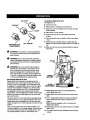
BRUSH ASSEMBLIES
See Figure24.
The muter has externally accessfble brush assemblies that
should periodically be checked for wear.
TOreplace brush assemblies;
Electdc tools used on fiberglass material, wallboard,
spackling compounds, or plaster are subject to
accelerated wear and possible premature failure because
the fiberglass chips and gdndings are highly abrasive to
bearings, brushes, commutators, etc. Consequently, we
do not recommended using this tool for extended work on
these types of materials. However, if you do work with any
of these materials, it is extremely important
to clean the
tool using compressed air.
• Unplug the router.
• Remove brush cap with a screwdriver. Brush assembly
Is springloaded and will pop cut when you remove
brushcap.
• Remove brush assembly (brush and spring}.
•
Check for wear. If worn, always replace in pairs. Do not
replace one side without replacing the other.
•
ReasserobIe using new brush assemblies. Make sure
curvature of brush matches curvature of motor and that
brush moves freely in brush tube.
Make sure brush cap is oriented correctly (straight) and
replace.
LUBRICATION
All of the bearings in this toci are tubdcated with a sufficient
amount of high grade lubricant for tile life of the unit under
normal operating conditions. Therefore, no further lubrication is required.
•
• Tighten brush cap securely. Do not over tighten.
Only the parts shown on the parts llst are intended to be
repa]red or replaced by the customer. All other parts should
be replaced at a Sears Service Center.
22
BRUSH
CAP
PLUNGE
LOCKLEVER
BRUSH
ASSEMBLY
I
BRUSH
ASSEMBLY
BRUSH
CAP
SCREW
Fig. 26
Fig. 24
PLUNGE LOCK LEVER
See Figure_ 25 - 27.
After extended use, the plunge lock may wear. )S
=this
happens, you can easily adjust the lever.
To ad)ust plunge lock lever:.
•
Unplug the muter.
•
•
•
Make sure lever is In locked position.
Remove the screw supporting the plunge lock lever.
Remove the lever.
•
Place the lever back in the odginal Cookedposition.
• Replace the screw.
• Check for free plunge with lever rotated to unlocked
position.If muter does not plunge freely, reposition
lever.
PLUNGELOCKLEVERSHOWN
AFTEREXTENDED
WEAR
PLUNGELOCKLEVERSHOWN
IN ORIGINALLOCKEDPOSITION
Fig. 25
23
Fig. 27
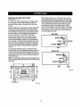
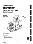
.....
CRAFTSMAN
PLUNGE
ROUTER
MODEL
NO. _,15.175"_70
SEENOTE
!
14
15
16
t
!
i
i
mlllll
ii
i
ii
i
i
ii
i
Ill
I
|11
II
Im
I
NOTE: The assemb/y shown represents an important part of the dccabbinsulated system. To avoid the
poss_i/1ty of sftaratfonor damage to the system, service should be pe,'formad by your n_,_restSears
raper center. Contact your nearest Sears ret_]l store for service center information.
I, ............
ii
i
IH
2¢
ii
i i
a
CRAFTSMAN
r
[
PLUNGE
ROUTER
MODEL
NO. 315.175170
The model number will be found on a plate attached to the motor housing. Always mention the modeT
number in all correspondence regarding your ROUTER or when ordering repair parts.
SEE BACK PAGE FOR PARTS ORDERING
1
INSTRUCTIONS
PARTS LIST
Key
No.
1
Part
Number
660325001
2
630005001
3
670342001
4
690141001
5
690002002
8
513640001
7
860221005
B
9¢0114137
9
550853001
10
200233002
11
940115119
12
13
660163002
670341001
14
860284003
15
550849002
18
660427001
17
18
Description
Qty.
" Screw (#8-24 x 7/16 in.) ..................................................................................
2
Cover Piate .................................................. _................................................... 1
Shaft Lock Pin ................................................................ ,................................ 1
Spring..............................................................................................................
Washer ............................................................................................................
1
1
Battery Cover .......................... :.......................................................................
* Screw ..............................................................................................................
1
1
Logo Label ......................................................................................................
Brush Cap .......................................................................................................
1
2
Brush Set Assembly ........................................................................................
Data Label .......................................................................................................
I
1
Hex Nut ...........................................................................................................
3
Plunge Depth Shaft .........................................................................................
I
" Screw (#6-32 x 1/4 in.) ....................................................................................
Plunge Lock Lever ...........................................................................................
1
1
512817001
Screw (MS x 1.25)............................................................................................
Dust Chute ......................................................................................................
1
1
670345001
1/2 in. Collet ....................................................................................................
1
1/4 in, Coffer Adaptor ......................................................................................
Subbase ..........................................................................................................
1
1
19
670344002
20
512816001
21
660136001
22
551014001
" Scrty_ {#10-32 x 1/4 in.) ..................................................................................
Dust Shield ......................................................................................................
3
I
23
514017001
Dust Control Adaptor ......................................................................................
1
24
25
300617010
971137001
Plunge Depth Knob Assembly ........................................................................
1
26
670346001
Spr_ng..............................................................................................................
15/16 In. Wrench .............................................................................................
1
1
27
750288001
28
671295001
3V Battery ........................................................................................................
Brush Tube ......................................................................................................
1
2
983000497
Operator's Manual (Not Shown)
" Standard Hardware Item - May Be Purchased Locally
25
For repair-in your home-of all major brand appliances,
lawn and garden equipment, or heating and cooling systems,
no matter who made it, no matter who sold it!
For the replacement parts, accessories and
owner's manuals that you need to do-it-yourself.
For Sears professional installation of home appliances
and items like garage door openers and water heaters.
1-8004-MY-HOME
®
(l..soo..4es-4ss3)
Calt anytime, day or night (U,S.A. and Canada)
www.sear_
com
www.sears.ca
Our Home
For repair of carry-in items like vacuums, lawn equipment,
and electronics, call or go on-line for the location of your nearest
Sears Parts & Repair Center,
1-800488-t
222
Call anytime, day or night (U.S,A, only)
w1Nw.$ears.corlt
To purchase a protection agreement (U.S.A.)
or maintenance agreement (Canada) on a product serviced by Sears:
1-800.827-6655
II
(U.S.A.)
1-800-36t-6665
(Canada)
Para pedir servicio de mmparaci6n
a dornicilio, y para ordenar piezas:
1-888-SU-HOGAR
_
Au Canada pour service en fran_:ais:
(1-888-784-642"/)
WWW.Se_r_oc_
....
...........
I"800-LE'FOYER
"c
(%800-533-6937}
Sears
® RegisteredTrademark I TM Trademark/ m SeMele It_ of _urs, Roetx_k and Co.
® Mama Reg]stradaI _ Mama de Fabdca/ m Mama de Sewiclo de Seam, Roebuckand Co.
t4o
MD
Mat'quede €ommome I
Marque d6pos6ede Seam. Roebuckand Co.
® _>_=r,J,R_ e:z_-._and Co.