1
555970
CONVENTIONAL
ROUTING OPERATIONS
WITH THE OVERARM
ROUTER
The Shopsmith Overarm Pin Router is also
well suited for more ordinary routing
operations . . . functioning in a very similar
fashion to more conventional under-table
router set-ups. There are a few differences:
• With the Overarm Router, your rotating
bit is almost always in plain view, providing an added measure of accuracy.
• Changing your depth-of cut (and seeing
your change as you make it) is a much
simpler matter with an Overarm Router.
For maximum efficiency, under-table routing requires a special router lifting device.
Such devices often expensive, adding a
couple of hundred dollars to the cost of a
router table.
• The improved visibility of your work-inprocess also makes forming stopped cuts
(such as travel slots, grooves, dadoes and
mortises) much easier and safer with an
Overarm Router.
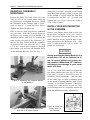
MARK V – MOUNTED OVERARM PIN ROUTER
rative cuts with non-piloted profile Bits.
Here’s the step-by-step process.
1. Set up your Overarm Router, following
the “General guidelines for overarm
routing” on page 18 in the front section
of this Manual.
2. Once you get started, always set your
depth-of-cut to make your first pass
very shallow. Doing so will give you far
better control over the accuracy of your
cut, since the rotating bit is much less
likely to grab or pull your workpiece off
your planned profile when your cuts are
shallow.
NOTE
In some cases, your lateral depth-of-cut
must also be adjusted to produce the profile you desire. With straight-edged workpieces, this can be accomplished by sliding your guiding Fence in or out. With irregular-shaped edges, just change the size
of the Guide Pin you’re using.
ROUTING AGAINST A TABLE PIN
3. Screw the appropriate sized Guide Pin
into the threaded hole in the center of
the Pin Routing Table Insert and tighten
it securely.
Against-the-Guide-Pin routing is usually
performed with a non-piloted router bit – on
a workpiece with irregular or rounded edges
that cannot be guided by the Fences. That’s
because the job of the pilots (solid or bearing-types) on piloted Bits are to control your
lateral depth-of-cut . . . and the profile they’re
making.
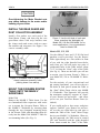
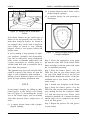
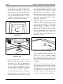
4. Position the Table Insert as shown in
Figure 23 and screw the 1/4" Starter Pin
into the threaded hole just to the left of
the center hole in the Plate. Tighten securely. When installing the Table Insert, the Starter Pin must always be positioned in the Insert so it is to the left
of the Guide Pin.
Since non-piloted Bits have no pilots to control their lateral depths-of-cut, you must rely
on Guide Pins to control this for you. Some
typical against-the-Pin operations include
creating special rabbet cuts (usually with
straight bits or slot cutters) and making deco-
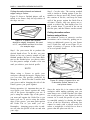
5. Prepare to make your cut. Lower the
Router into the position and lock it securely. Turn on your Router motor. Resting the edge of your workpiece against
the Starter Pin, ease it gradually into the
rotating bit to start your cut. Continue
30