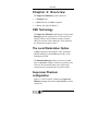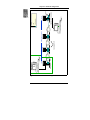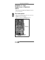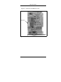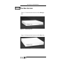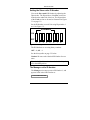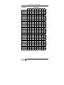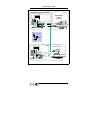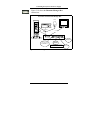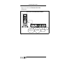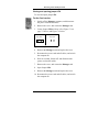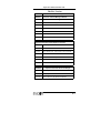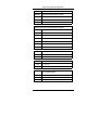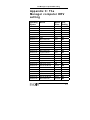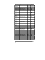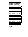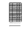
1
Welcome to your Supervisor Phantom System
The Supervisor Phantom System is produced by Minicom
Advanced Systems Limited, and includes new features that are
described later in this User’s Guide, Version 10400.
Technical precautions
This equipment generates radio frequency energy and if not
installed in accordance with the manufacturer’s instructions,
may cause radio frequency interference.
This equipment complies with Part 15; Subpart J of the FCC
rules for a Class A computing device. This equipment also
complies with the Class A limits for radio noise emission from
digital apparatus set out in the Radio Interference Regulation of
the Canadian Department of Communications. These above
rules are designed to provide reasonable protection against
such interference when operating the equipment in a
commercial environment. If operation of this equipment in a
residential area causes radio frequency interference, the user,
and not Minicom Advanced Systems Limited, will be
responsible.
Changes or modifications made to this equipment not expressly
approved by Minicom Advanced Systems Limited could void
the user’s authority to operate the equipment.
Minicom Advanced Systems Limited assumes no responsibility
for any errors that appear in this document. Information in this
document is subject to change without notice.
No part of this document may be reproduced or transmitted in
any form or by any means, electronic or mechanical, for any
purpose, without the express written permission of Minicom
Advanced Systems Limited.
© 2000 Minicom Advanced Systems Limited. All rights
reserved.
Trademarks
AT and PS are registered trademarks of International Business
Machines Corporation. All other trademarks and registered
trademarks are the property of their respective owners.
5UM20044 Version 10400
Table of Contents
Table of Contents
CHAPTER 1: INTRODUCTION
1-1
The Supervisor Phantom Versions
1-1
Icons
1-1
The system
1-2
CHAPTER 2: OVERVIEW
2-1
OSD Technology
2-1
The Local Workstation Option
2-1
Supervisor Phantom configuration
2-1
CHAPTER 3: THE SUPERVISOR PHANTOM UNITS
3-1
The Card version
3-1
The Box Version
3-3
Setting the Slave unit’s ID Number
3-4
The Manager unit’s ID Number
3-4
CHAPTER 4: INSTALLING THE CARD VERSION OF THE
SUPERVISOR PHANTOM
4-1
CHAPTER 5: CONNECTING THE SYSTEM
5-1
Connecting the Supervisor Phantom Manager Unit
5-1
Connecting to an AT type computer
5-3
Connecting the System cable
5-3
Keyboard/Mouse In/Out cable for PS type computers
5-4
Connecting the Screen In/Out cable
5-6
Connecting the Supervisor Phantom Slave Unit
5-7
Local Workstation
5-7
Connecting the Slave Unit
5-7
Keyboard/Mouse cable for PS
5-9
Connecting the Slave Screen cable
5-10
Connecting the System Cable
5-11
Connecting the Slave Unit with a Local Workstation
5-12
Connecting the System cable
5-12
Connecting the Keyboard/Mouse In/Out Cable
5-13
Connecting the Slave Screen In/Out cable
5-14
Connecting the Supervisor Phantom Units to an AT type computer 5-15
Adapter cables for the Slave Unit
5UM20044 Version 10400
5-15
i
Table of Contents
Connecting the Mouse adapter cable
5-16
Connecting the keyboard In adapter cable
5-16
Adapter cables for the Manager or the Slave Unit with a Local
Workstation
5-16
Connecting the Mouse adapter cable
5-17
Connecting the Keyboard In adapter cable
5-17
Connecting the Keyboard Out adapter cable
5-17
CHAPTER 6: THE OSD FUNCTIONS
6-1
Displaying the OSD
6-1
The Name section
6-1
The Stations section
6-2
Line Color codes
6-2
Selecting a Computer
6-2
Image Adjusting
6-3
The Edit Mode window
6-3
Navigating between sections
6-4
Editing options
6-5
Editing the Name section
6-5
Editing the Stations section
6-5
Editing a group of lines in the Stations section
6-6
Saving changes
6-6
The Setup window
6-6
Changing the SCAN and DISP time spans
6-7
Navigating between the SCAN and DISP columns
6-8
Changing the time span of a group of computers
6-8
Removing a computer from the scanning sequence
6-8
Constantly displaying a Slave computer
6-9
Changing the KB column
6-9
The DRV column
6-9
The Manager computer setting
6-9
The Slave computer setting
6-10
Changing the setting in DRV column
6-10
The MOUSE column
6-10
Changing the OSD Display Hot-key
6-10
Changing the Keyboard Language
6-11
Skipping out unconnected or switched off computers
6-11
ii
5UM20044 Version 10400
Table of Contents
Scanning Computers
6-12
The Help Menu window
6-12
Closing the OSD
6-13
Reverting to the factory set OSD
6-13
For the Card version
6-13
For the Box version
6-15
CHAPTER 7: PASSWORD PROTECTING THE OSD
7-1
Administrator Status
7-1
Supervisor Status
7-1
User Status
7-1
Enabling password protection
7-2
For the Card version
7-2
For the Box version
7-3
Entering a password
7-3
Setting up a password
7-4
Changing a password
7-5
Reverting to the default password
7-5
Closing and opening jumper JP4
7-6
For the Card version
7-6
For the Box version
7-7
CHAPTER 8: UPGRADING THE SUPERVISOR PHANTOM
FIRMWARE
8-1
System Requirements for the Phantom Update software
8-1
Connecting the Communication cable
8-2
Installing the software
8-3
Starting and Configuring Phantom Update
8-3
The F10 Upgrade Hot-key
8-5
Verifying the Version Numbers
8-5
The OSD Version Number
8-5
The Phantom Manager version number
8-6
Verifying the Slave Version Number
8-6
Updating the Firmware
8-7
Troubleshooting Tips
8-9
The Manager unit
8-9
Electricity failure
8-9
The Slave unit
8-11
5UM20044 Version 10400
iii
Table of Contents
Electricity failure or rattling noise
8-11
APPENDIX A: TECHNICAL SPECIFICATIONS
A-1
APPENDIX B: SUPERVISOR PHANTOM PRODUCT LINE
B-1
APPENDIX C: THE MANAGER COMPUTER DRV SETTING
C-1
APPENDIX D: THE SLAVE COMPUTER DRV SETTING
D-1
INDEX
iv
I
5UM20044 Version 10400
Introduction
Chapter 1: Introduction
The Supervisor Phantom is a keyboard, video, and
mouse (KVM) distribution switch. With the
Supervisor Phantom, you can connect up to 32
computers in one system.
The Supervisor Phantom
Versions
The Supervisor Phantom comes in two versions. The
internal PCI Card version, and the external Box
version.
This User’s Guide describes the installation and
operation of both versions.
Icons
Chapters or paragraphs that apply to one particular
version, are clearly marked throughout the Guide with
one of the following icons:
For the Card version -
For the Box version The two versions of the Supervisor Phantom are
fully compatible with each other.
1-1
The system
The system
The Supervisor Phantom system is linked in a daisychain pattern by 100 Base-T4 CAT5 FTP cables.
The Supervisor Phantom is compatible with:
•
IBM compatible AT, PS, or Mixed Type computers.
Silicon Graphics or Unix computers.
•
VGA, SVGA, or XGA video standards.
•
All major computer and server manufacturers.
•
IntelliMouse™, Logitech WheelMouse and IBM
Trackpoint.
•
Microsoft, DOS, Windows 3.1, 95, 98 and 2000. Novel,
UNIX, Linux, SGI and BeOS.
The Supervisor Phantom gives you:
•
Control and monitoring capabilities over 31 Slave
computers from one Manager unit.
•
The option to connect a Keyboard, Video and Mouse –
referred to as a Local Workstation - to any Slave
computer.
•
A transmission range of up to 110m/360ft.
•
Matrix configurations of up to 6 x 31.
1-2
5UM20044 Version 10400
Overview
Chapter 2: Overview
The Supervisor Phantom system consists of:
•
A Manager unit.
•
A Slave unit for each Slave computer.
•
Cabling - described in chapter 5.
OSD Technology
The Supervisor Phantom superimposes a menu on the
Manager position computer screen. This On-ScreenDisplay (OSD) consists of three sections. From the
OSD, you activate various functions. These functions
are discussed in chapters 6 and 7.
The Local Workstation Option
A Slave computer with keyboard, video, and mouse
(KVM) attached is called a Slave unit with a Local
Workstation (LWS).
The Phantom Manager and the local user can both
work on the Slave computer with a one second AccessTimeout. This means that when one of them stops
working for one second the other can take control.
Supervisor Phantom
configuration
Figures 2-1 and 2-2 below, illustrate the Supervisor
Phantom configuration for the Card and Box versions
respectively.
2-1
2-2
CPU 1
Manager Computer
OSD
MENU
MANAGER POSITION
PS or AT
Slave Computers PS or AT
Maximum Distance 110 m/360 ft
Manager
CPU 32
Terminator
Slave Computer with Local workstation
RJ45F System Port
Slave
Supervisor Phantom configuration
Figure 2-1 The Card Version Configuration
5UM20044 Version 10400
Overview
Manager Box
KB/M SCREEN I/O
Computer
SYSTEM OUT RS 232 ON
OFF POWER
System Cable
OUT
IN
Computer
KB/M
SCREEN I/O
SYSTEM
ON
OFF POWER
ON
OFF POWER
Slave
Box
System Cable
OUT
KB/M
SCREEN I/O
IN
SYSTEM
Slave
Box
Computer
Terminator
Figure 2-2 The Box Version Configuration
2-3
The Supervisor Phantom units
Chapter 3: The
Supervisor Phantom
units
Both versions of the Supervisor Phantom incorporate
the same technology.
The Card version
There are two different types of PCI cards. One for the
Manager, and one for the Slave.
Figure 3-1, illustrates the Manager PCI card.
Slots onto
Motherboard
Bracket
Figure 3-1 The Manager card
3-1
The Card version
Figure 3-2 illustrates the Slave PCI card.
Dipswitches
Figure 3-2 The Slave card
3-2
5UM20044 Version 10400
The Supervisor Phantom units
The Box Version
Figure 3-3 illustrates the front view of the Manager
box.
Figure 3-3 The Manager box
Figure 3-4 illustrates the front view of the Slave box.
Figure 3-4 The Slave box
3-3
The Box Version
Setting the Slave unit’s ID Number
You set the Slave unit’s ID Number by adjusting the
Dipswitches. The Dipswitches of the Box version are
located on the underside of the box. The Dipswitches
of the Card version are located as illustrated in Figure
3-2 on page 3-2.
Set the ID Number on each Unit using Dipswitches 1
to 6. See Figure 3-5.
ID NUMBER
ON
OFF
1
2
3
4
5
6
7
8
Figure 3-5 Setting the ID Number
The ID Numbers are set using binary numbers.
OFF = 0, ON = 1.
See the binary table on page 3-5 below.
Caution! Do not set the identical ID Number for two
units.
Dipswitches 7 and 8 are inactive and should always be
set to the OFF position.
The Manager unit’s ID Number
The Manager unit comes preset to ID Number 1, and
appears listed in the OSD window as:
1 PHANTOM MANAGER
3-4
5UM20044 Version 10400
The Supervisor Phantom units
Slave No.
2
3
4
5
6
7
8
9
10
11
12
13
14
15
16
17
18
19
20
21
22
23
24
25
26
27
28
29
30
31
32
ID Numbers
1
2
3
4
5
6
7
8
0
1
0
1
0
1
0
1
0
1
0
1
0
1
0
1
0
1
0
1
0
1
0
1
0
1
0
1
0
1
0
1
1
0
0
1
1
0
0
1
1
0
0
1
1
0
0
1
1
0
0
1
1
0
0
1
1
0
0
1
1
0
0
0
1
1
1
1
0
0
0
0
1
1
1
1
0
0
0
0
1
1
1
1
0
0
0
0
1
1
1
1
0
0
0
0
0
0
0
1
1
1
1
1
1
1
1
0
0
0
0
0
0
0
0
1
1
1
1
1
1
1
1
0
0
0
0
0
0
0
0
0
0
0
0
0
0
0
1
1
1
1
1
1
1
1
1
1
1
1
1
1
1
1
0
0
0
0
0
0
0
0
0
0
0
0
0
0
0
0
0
0
0
0
0
0
0
0
0
0
0
0
0
0
0
1
0
0
0
0
0
0
0
0
0
0
0
0
0
0
0
0
0
0
0
0
0
0
0
0
0
0
0
0
0
0
0
0
0
0
0
0
0
0
0
0
0
0
0
0
0
0
0
0
0
0
0
0
0
0
0
0
0
0
0
0
0
0
3-5
Installing the Card version of the Supervisor Phantom
Chapter 4: Installing the
Card version of the
Supervisor Phantom
Prior to installing the Card:
•
Switch off all computers.
•
Disconnect all power cords.
•
In order to avoid electrostatic damage to the Card;
discharge any static electricity you may be carrying.
You can do this by touching any grounded object.
To install the Supervisor Phantom Card:
1.
Remove computer covers.
2.
Insert the Manager unit into any available PCI
slot of one computer.
3.
Insert the Slave units into any available PCI slot
of the other computers.
4.
Replace computer covers.
4-1
Connecting the System
Chapter 5: Connecting
the System
Before connecting the Supervisor Phantom system:
•
Switch off all computers.
•
Place cables away from fluorescent lights, air
conditioners, and machines that are likely to generate
electrical noise.
•
Ensure that the total cable length between the
Manager unit and the last Slave unit, does not
exceed 110 m / 360 ft.
Connecting the Supervisor
Phantom Manager Unit
Figure 5-1 below illustrates the ports on the Card
version Manager unit.
Keyboard/Mouse
In/Out
Screen In/Out
System Out
Communication
Figure 5-1 The Card version Manager unit
5-1
Connecting the Supervisor Phantom Manager Unit
Figure 5-2 illustrates the ports on the Box version
Manager unit.
Screen
In/Out
System
Out
Keyboard/Mouse
In/Out
On/Off
Switch
Power
LED
Power
Connector
Communication
Figure 5-2 The Box version Manager unit
Both versions of the Manager Unit use the following
four cables:
•
System cable.
•
Communication cable.
•
Keyboard/Mouse In/Out cable for PS type CPUs.
•
Screen In/Out cable.
The latter two cables are longer for the Box version
than for the Card version.
Only the Box Version of the Manager unit uses the
following:
•
Power Adapter.
•
Power Cord.
5-2
5UM20044 Version 10400
Connecting the System
Connecting to an AT type computer
There are special Adapter cables to connect the
Supervisor Phantom Manager to an AT type CPU.
These Adapter cables are in addition to the above
mentioned cables. See page 5-15 for further details.
Connecting the System cable
The System cable consists of a single 4-pair 100 BaseT4 CAT5 FTP (Foiled Twisted Pair) cable with RJ45M connectors attached at each end. Figure 5-3
illustrates the FTP cable.
RJ-45M
Figure 5-3 The FTP System Cable
Figure 5-4 illustrates the RJ-45M pinout and wire
diagram.
1 - Orange
2 - Orange/White
3 - Blue
4 - Green/White
5 - Green
6 - Blue/White
7 - Brown
8 - Brown/White
78
56
34
12
Figure 5-4 The RJ-45M Connector
5-3
Connecting the Supervisor Phantom Manager Unit
To connect the System cable to the Phantom
Manager:
1. Connect one of the System Cable’s RJ45M
connectors to the Phantom Manager’s System
Out port.
2. Connect the other System Cable’s RJ45M
connector to a Phantom Slave’s System In port.
Keyboard/Mouse In/Out cable for PS
type computers
Figure 5-5 below illustrates the Keyboard/Mouse
In/Out cable.
To connect the Keyboard/Mouse In/Out cable to the
Phantom Manager:
1. Connect the cable’s MiniDIN8M connector to the
Manager’s Keyboard/Mouse In/Out port.
2. Connect the MiniDIN6F Mouse Out connector to
the mouse’s MiniDIN6M connector.
3. Connect the MiniDIN6M Mouse In connector to the
mouse port on the CPU’s rear panel.
4. Connect the MiniDIN6F Keyboard Out connector to
the keyboard’s MiniDIN6M connector.
5. Connect the MiniDIN6M Keyboard In connector to
the Keyboard port on the CPU’s rear panel.
5-4
5UM20044 Version 10400
Connecting the System
MiniDIN8M to
Phantom
MiniDIN6F
to Mouse
MiniDIN6F
to Keyboard
MiniDIN6M to
CPU’s Mouse
port
MiniDIN6M to
CPU’s
Keyboard port
Figure 5-5 The Manager K/M In/Out Cable for PS
5-5
Connecting the Screen In/Out cable
C
h
a
p
t
e
r
5
:
Connecting the Screen In/Out cable
Figure 5-6 below illustrates the Screen In/Out cable.
To connect the Screen In/Out cable to the Phantom
Manager:
1. Connect the cable’s connector #(1) to the
Manager’s Screen In/Out port.
2. Connect the monitor’s Screen cable to the cable’s
connector #(2).
3. Connect the cable’s connector #(3) to the Screen
port on the CPU’s rear panel.
(3)
HDD15M to CPU’s
Screen port
(2)
HDD15F to Screen
HDD15F to
Phantom
(1)
Figure 5-6 The Manager Screen In/Out Cable
5-6
5UM20044 Version 10400
Connecting the System
C
h
a
p
t
e
r
5
:
Connecting the Supervisor
Phantom Slave Unit
The Supervisor Phantom Slave unit is compatible
with the following computer types:
•
AT.
•
PS.
•
Mixed Type, combining PS and AT computers in
the same system.
Local Workstation
You have the option to connect a Local Workstation to
one or all of the Slave computers. You can then work
with the Slave computer locally.
Connecting the Slave Unit
Figure 5-7 illustrates the ports on the Card version
Slave unit.
Keyboard/Mouse
In/Out
Screen In/Out
Power
LED
System Out
System In
Figure 5-7 The Card version Slave unit
5-7
Connecting the Supervisor Phantom Slave Unit
Figure 5-8 illustrates the ports on the Box version of the
Slave unit.
Screen
System Out
System In
Keyboard/Mouse
Power
LED
Power
Connector
ON/Off Switch
Figure 5-8 The Box version Slave unit
Both versions of the Phantom Slave use the following
3 cables:
•
System cable.
•
Keyboard/Mouse cable for PS.
•
Screen cable.
The latter two cables are longer for the Box version
than for the Card version.
Only the Box Version of the Slave unit uses the
following:
•
Power Adapter.
•
Power Cord.
5-8
5UM20044 Version 10400
Connecting the System
Keyboard/Mouse cable for PS
Figure 5-9 illustrates the Keyboard/Mouse cable for PS.
To connect the Keyboard/Mouse cable for PS type
computers to the Phantom Slave:
1. Connect the cable’s MiniDin8M connector to the
Slave’s MiniDin8F port.
2. Connect the MiniDin6M mouse connector to the
Mouse port on the CPU’s rear panel.
3. Connect the MiniDin6M Keyboard connector to the
Keyboard port on the CPU’s rear panel.
MiniDIN6M to
CPU’s Keyboard
port
MiniDIN6M to
CPU’s Mouse port
MiniDIN8M to
Phantom
Figure 5-9 The Slave KB/Mouse Cable for PS
5-9
Connecting the Slave Screen cable
C
h
a
p
t
e
r
5
:
Connecting the Slave Screen cable
Figure 5-10 illustrates the Screen cable.
To connect the Screen cable to the Phantom Slave:
1.
Connect the cable’s HDD15F connector to the
Slave’s HDD15M Screen port.
2.
Connect the cable’s HDD15M connector to the
HDD15F screen port on the CPU’s rear panel.
HDD15F to
Phantom
HDD15M to CPU’s
screen port
Figure 5-10 The Slave Screen cable
5-10
5UM20044 Version 10400
Connecting the System Cable
C
h
a
p
t
e
r
5
:
Connecting the System Cable
The System cable links the Supervisor Phantom
Manager and Slaves in a daisy-chain pattern, see
Figure 5-11.
To connect the System cable to each Slave unit:
1.
Connect one RJ45M connector to the first
Slave’s RJ45F System Out port.
2.
Connect the other RJ45M connector to the next
Slave’s RJ45F System In port.
Connect all the Slaves in this way.
Connect a Terminator to the RJ45F System Out port of
the last Slave in the series.
PHANTOM MANAGER
SLAVE 1
SLAVE 2……. SLAVE 31
IN
IN
IN
OUT
OUT
OUT
OUT
TERMINATOR
Figure 5-11 The System cable connections
You can also connect each unit to the unit that is
physically closest to it. For example, you can connect
the Supervisor Phantom Manager to Slave #4, and
Slave #4 to Slave #2.
Before installing the System cable, we recommend that
you work out how to connect all the units using the
shortest possible length of cable. A shorter cable length
increases video quality, and reduces noise.
5-11
Connecting the Slave Unit with a Local Workstation
Connecting the Slave Unit with a Local
Workstation
When a Phantom Slave has a Local Workstation
attached, you connect the following cables to that
Slave unit:
Both versions of the Phantom Slave use the following
3 cables:
•
System cable.
•
Keyboard/Mouse In/Out cable for PS.
•
Screen In/Out cable.
The latter two cables are longer for the Box version
than for the Card version.
Only the Box Version of the Slave unit uses the
following:
•
Power Adapter.
•
Power Cord.
Connecting the System cable
To connect the System cable, see page 5-11.
5-12
5UM20044 Version 10400
Connecting the System Cable
Connecting the Keyboard/Mouse In/Out
Cable for PS type computers
Figure 5-12 illustrates the Keyboard/Mouse In/Out
cable.
To connect the Keyboard/Mouse In/Out cable to the
Phantom Slave:
1. Connect the cable’s MiniDin8M connector to the
Slave’s MiniDin8F port.
2. Connect the MiniDIN6F Mouse Out connector to
the mouse’s MiniDIN6M connector.
3. Connect the MiniDIN6M Mouse In connector to the
mouse port on the CPU’s rear panel.
4. Connect the MiniDIN6F Keyboard Out connector to
the keyboard’s MiniDIN6M connector.
5. Connect the MiniDIN6M Keyboard In connector to
the Keyboard port on the CPU’s rear panel.
MiniDIN8M to
Phantom
MiniDIN6F
to Mouse
MiniDIN6F
to Keyboard
MiniDIN6M to
CPU’s Mouse
port
MiniDIN6M to
CPU’s
Keyboard port
Figure 5-12 The Slave LWS K/M In/Out Cable
5-13
Connecting the Mouse adapter cable
C
h
a
p
t
e
r
5
:
Connecting the Slave Screen In/Out cable
Figure 5-13 illustrates the Slave Screen In/Out cable
To Connect the Screen In/Out cable to the Phantom
Slave:
1.
Connect the cable’s connector #(1) – see Figure
5-13 below - to the Slave Unit’s Screen In/Out
port.
2.
Connect the monitor’s screen cable to the cable’s
connector #(2).
3.
Connect the cable’s connector #(3) to the screen
port on the CPU’s rear panel.
(3)
HDD15M to CPU’s
Screen port
(2)
HDD15F to Screen
HDD15F to
Phantom
(1)
Figure 5-13 The Slave LWS Screen In/Out cable
5-14
5UM20044 Version 10400
Connecting the System
Connecting the Supervisor Phantom
Units to an AT type computer
You can connect all the units of both the Card and
Box versions of the Supervisor Phantom, to an AT
type computer.
There are two adapter cables for the Phantom Slave,
and three for the Manager or Slave with a LWS.
Note! You must always use a PS type mouse.
Adapter cables for the Slave Unit
The two cables are:
•
Mouse adapter cable. See Figure 5-14.
•
Keyboard In adapter cable. See Figure 5-15.
Both cables connect to the Slave Keyboard/Mouse
cable. See Figure 5-9 on page 5-9.
DB9F to CPU’s Serial
Mouse port
MiniDIN6F to
MiniDIN6M MOUSE
IN Connector
Figure 5-14 The Mouse adapter cable
DIN5M to CPU’s
Keyboard port
MiniDIN6F to
MiniDIN6M
KEYBOARD IN
Connector
Figure 5-15 The Keyboard In adapter cable
5-15
Connecting the Mouse adapter cable
Connecting the Mouse adapter cable
Connect the Mouse adapter cable’s:
1.
MiniDIN6F to the Keyboard/Mouse MiniDIN6M
MOUSE IN connector.
2.
DB9F to the CPU’s Serial Mouse port.
Connecting the keyboard In adapter cable
Connect the Keyboard In adapter cable’s:
1.
MiniDIN6F to the Keyboard/Mouse MiniDIN6M
KEYBOARD IN connector.
2.
DIN5M to the CPU’s Keyboard port.
Adapter cables for the Manager or the Slave
Unit with a Local Workstation
The three cables are:
•
Mouse adapter cable. See Figure 5-14 above.
•
Keyboard In adapter cable. See Figure 5-15 above.
•
Keyboard Out adapter cable. See Figure 5-16 below.
DIN5F to
Keyboard
MiniDIN6M to
MiniDIN6F
KEYBOARD
OUT
Connector
Figure 5-16 The Keyboard Out adapter cable
5-16
5UM20044 Version 10400
Connecting the System
All three cables connect to the Manager or Slave
Keyboard/Mouse In/Out cable. See Figures 5-5 and 512 on pages 5-5 and 5-13 respectively.
Connecting the Mouse adapter cable
Connect the Mouse adapter cable’s:
1.
MiniDIN6F to the Keyboard/Mouse In/Out
MiniDIN6M MOUSE IN connector.
2.
DB9F to the CPU’s Serial Mouse port.
Connecting the Keyboard In adapter cable
Connect the Keyboard In adapter cable’s:
1.
MiniDIN6F to the Keyboard/Mouse In/Out
MiniDIN6M KEYBOARD IN connector.
2.
DIN5M CPU’s Keyboard port.
Connecting the Keyboard Out adapter cable
Connect The Keyboard Out adapter cable’s:
1.
MiniDIN6M to the Keyboard/Mouse In/Out
cable’s MiniDIN6F KEYBOARD OUT
connector.
2.
DIN5F to the Keyboard.
5-17
Connecting the System to the Power Supply
C
h
a
p
t
e
r
5
:
Connecting the System to the Power Supply
The Card version
The Manager and Slave units draw their power via
the computer’s motherboard.
The Box version
The Manager and Slave units draw their power from
the electricity supply via a Power adapter and Power
cord.
Connecting the Power Adapter and Power Cord
1.
Connect the Power Adapter’s DIN4M connector
to the Slave’s Power connector.
2.
Connect the Power Adapter’s Power connector
to the Power cord.
3.
Connect the Power cord to the wall socket.
The Supervisor Phantom
configuration
Figure 5-17 below shows the Supervisor Phantom
Card system connections in detail.
5-18
5UM20044 Version 10400
Connecting the System
MiniDin6M to Keyboard port
HDD15M to Screen port
DB9F to Com. port
MANAGEMENT
POSITION
Computer 1
Plug
OSD
MENU
RJ45M
OUT
HDD15F
MiniDin8M
Management Computer PS/2
MiniDin6M to Mouse port
OSD
MENU
Management PS/2
Computer 1
Slave PS/2
Computer 2
with optional
KVM
MiniDin6M to Keyboard port
HDD15M to Screen port
Slave Computer 2
RJ45M
IN
To RJ45F System In port
of Slave Computer 3
OUT
HDD15F
MiniDin8M
Slave Computer PS/2 with Optional KVM
MiniDin6M to Mouse port
Figure 5-17 The Supervisor Phantom Card system connections
5-19
Connecting the System to the Power Supply
Figure 5–18 shows the Phantom Manager Box
connections.
Connection of the Phantom Manager Box.
Mouse
Monitor
Keyboard
5CB10379
5CB10378
KB/M
SCREEN I/O
SYSTEM OUT
RS 232 ON
OFF
POWER
Computer
Connect Power
supply
Connect FTP
system cable between this
connector and IN connector on
Slave unit.
Connect Serial
RS232 cable for
Download feature
This cable is optional and not needed for
regular operation of the Phantom
ON/OFF switch
Figure 5–18 The Manager Box connections
5-20
5UM20044 Version 10400
Connecting the System
Figure 5–19 shows the Phantom Slave Box
connections.
Connection of the Phantom Slave Box.
5CB10376
5CB10377
OUT
KB/M
SCREEN I/O
IN
SYSTEM
ON
OFF POWER
Computer
Connect Power
supply
Connect FTP
system cable to the next
Phantom Slave unit in the
chain
Connect FTP
system cable to the
previous Phantom Slave
unit in the chain
ON/OFF switch
Figure 5–19 The Slave Box connections
5-21
The OSD functions
Chapter 6: The OSD
functions
You control and monitor the Slave computers in the
Supervisor Phantom system through an On-ScreenDisplay (OSD) on the Manager screen. The OSD
contains a number of windows which are accessed using
Hot-keys. Each window has its own special functions.
Displaying the OSD
To display the OSD:
Press Shift, Shift. The Main window appears. See Figure
6-1. You access all the other windows from the Main
window
The OSD is divided into three sections. These are:
•
Name.
•
Stations.
•
Instructions and Hot-keys (discussed later).
Name
Stations
Type CPU
number here
Instructions
And
Hot-keys
Figure 6-1 The Main window
The Name section
The Name section displays the name as illustrated in
Figure 6-1.
6-1
The Stations section
The Stations section
The Stations section displays the computers in groups of
eight (1 - 8, 9 - 16, 17 - 24, and 25 - 32).
To navigate between the groups:
Use the Up and Down Arrow keys.
Line Color codes
Each computer line can be one of three colors. The
meaning of these colors is as follows:
Yellow
Connected and switched on computer.
Black
Connected and switched on computer with a
Local Workstation attached and presently
being used locally. After remaining idle for 30
seconds, it changes to yellow.
Blue
Unconnected or switched off computer.
Selecting a Computer
You monitor or control a Slave computer from the Main
window.
To select a computer:
1.
Navigate to the desired computer with the Up and
Down Arrow keys.
Or
In the “SELECT COMPUTER” line, type the
computer number. See Figure 6-1.
2.
6-2
Press Enter. The selected Slave’s screen replaces the
Manager’s screen. A Confirmation tag appears
showing which Slave computer is accessed. See
Figure 6-2.
5UM20044 Version 10400
The OSD functions
Figure 6-2 The Confirmation tag
To return to the Manager screen:
Press Shift, Shift.
Image Adjusting
You can adjust the image of any Slave computer screen
from the Main window.
To adjust the screen image:
1.
Navigate to the Slave computer you wish to adjust.
2.
Press F5. The screen image of the selected computer
appears, together with the Image Adjusting tag. See
Figure 6-3.
Figure 6-3 The Image Adjusting tag
3.
Adjust the image by using the Right and Left Arrow
keys.
4.
Press Esc.
Note! Picture quality is relative to distance. The further
away a Slave computer is from the Manager position, the
lower the image quality.
The Edit Mode window
You edit data in the Edit Mode window.
To display the Edit Mode window:
Press F2. The words “EDIT MODE” and the relevant
instructions appear, see Figure 6-4.
6-3
The Edit Mode window
Name
Stations
Instructions
Figure 6-4 The Edit Mode window
Navigating between sections
You can edit the text in both the Name and Stations
sections.
To navigate between the Name and Station sections, use
the Up and Down Arrow keys.
6-4
5UM20044 Version 10400
The OSD functions
Editing options
The editing options below apply to all OSD windows in
which you can edit characters.
You can either overwrite or erase a character.
To overwrite a character:
1.
Navigate to it using the Arrow keys.
2.
Type the new character.
To erase a character:
1.
Navigate to it using the Arrow keys.
2.
Press the Space bar. The character disappears. A
blank space replaces the erased character.
To erase a sequence of characters:
1.
Navigate to the first character in the sequence.
2.
Press and hold the Space bar down until you erase
the sequence.
Editing the Name section
You can substitute the text in the Name section with up to
30 characters in each of the two lines. A space constitutes
a character.
Editing the Stations section
The numbering at the start of each line is fixed, and
cannot be edited.
You can substitute the data that appears after the number
with up to 20 characters per line.
6-5
The Setup window
Editing a group of lines in the Stations section
You can edit a group of lines with the same data change.
To edit a group:
1.
Navigate to the first line you want to change.
2.
Type the desired change.
3.
Press End, End. The rest of the column downwards
takes on the same change.
Saving changes
To save changes in all OSD windows and return to the
Main window:
Press Esc.
The Setup window
You set parameters, and configure settings, in the Setup
window.
To display the Setup window:
Press F3. The Setup window with the relevant
instructions and Hot-keys appears. See Figure 6-5.
Figure 6-5 The Setup window
6-6
5UM20044 Version 10400
The OSD functions
The Setup window contains 6 columns, as follows:
Column
Function
Numbers
Computer numbers in groups of 8
SCAN
Scanning time period in seconds
DISP
Confirmation tag display time in seconds
KB
The keyboard mode, either PS or Unix
DRV
The mouse driver type
MOUSE
The mouse type
In the DISP column, you determine the amount of time
the Manager screen displays the Confirmation tag - see
Figure 6-2 - showing which Slave computer is being
accessed.
Changing the SCAN and DISP time spans
The SCAN and DISP time spans are preset to 030
seconds. You can adjust these times to suit your needs.
To change the time span:
1.
Navigate with the Arrow keys to the time span you
want to change.
2.
Type the desired time span.
3.
Press Esc.
When typing over a group of three digits, the cursor
automatically reverts to the first digit once you edit the
third digit.
6-7
The Setup window
Navigating between the SCAN and DISP columns
To move horizontally, between the first digit in the SCAN
column and the first digit in the DISP column:
Press Tab.
Or;
The Right and Left Arrow keys.
Changing the time span of a group of
computers
You can change the time spans of the SCAN and DISP
columns from a particular computer downwards.
To change the time span:
1.
Navigate to the time span of the first computer you
wish to change.
2.
Type the desired change.
3.
Press End, End. The remainder of the column takes
on the same change.
4.
Press Esc.
Removing a computer from the scanning
sequence
To remove a computer from the scanning sequence:
1.
Type 000 in the SCAN column.
2.
Press Esc.
6-8
5UM20044 Version 10400
The OSD functions
Constantly displaying a Slave computer
To constantly display a Slave computer:
1.
Type 999 in the SCAN column.
2.
Press Esc.
Changing the KB column
You need to set the KB mode to UN when working on a
UNIX computer. Otherwise, set the KB column to PS.
To change the KB column from PS to UN or vice versa:
1.
Place the cursor on the first character.
2.
Press the Spacebar. The display interchanges
between PS and UN.
3.
Press Esc.
The DRV column
The Supervisor Phantom system can function with
computers that have different operating systems, and
different mouse types. Each mouse type has it own
particular Mouse driver.
The Manager computer always has a mouse attached.
This is not necessarily the case with the Slave computer.
The Manager computer setting
Determine the setting for the Manager computer in the
DRV column by matching the computer’s operating
system and mouse type. See Appendix C.
6-9
The Setup window
The Slave computer setting
Determine the setting for the Slave computer in the DRV
column by matching the operating system and mouse type
of each computer in the table. See Appendix D.
Changing the setting in DRV column
To change the setting in DRV column:
1.
Place the cursor on the first character.
2.
Press the Spacebar. The display interchanges
between the different possible settings. Continue
pressing until you reach the required setting.
3.
Press Esc.
Note! When you don’t know which mouse driver is
installed, set the listing in the DRV column to PS.
The MOUSE column
The Mouse column and the DRV column are interrelated.
When you change the setting in the DRV column, the
listing in the Mouse column will automatically change to
match the DRV column.
Changing the OSD Display Hot-key
The default Hot-key to display the OSD, is Shift, Shift.
You can replace this Hot-key with any of the following:
• Ctrl, Ctrl.
• Ctrl, F11.
• Ctrl, F12.
6-10
5UM20044 Version 10400
The OSD functions
With a choice of four different Hot-keys, you can operate
up to four OSDs from one KVM position. Each OSD will
then have a different display Hot-key. This is useful for
cascading systems of for example, the Supervisor MU,
Pro, and Phantom.
To change the Hot-key:
1.
Press F9. The Hot-key changes from Shift, Shift to
Ctrl, Ctrl. Continue pressing until you reach the
required Hot-key.
2.
Press Esc.
Changing the Keyboard Language
The keyboard language is preset to US English. You can
change it to German, or French.
To Change the Keyboard Language:
1.
Press F8 until you reach the desired language.
2.
Press Esc.
Skipping out unconnected or switched off
computers
When navigating through the list of computers, you can
skip out the unconnected or switched off computers. You
do this with Autoskip. By default, Autoskip is activated.
To activate or deactivate Autoskip:
Press F6.
Note! Autoskip will also skip any active computer set to
000 in the SCAN column.
When Autoskip is inactive and the computer being
scanned is switched off, then the Manager screen appears
dark.
6-11
Scanning Computers
Scanning Computers
You scan computers from the Main window.
To start scanning:
Press F4. During scanning a Confirmation tag appears,
showing which Slave computer is presently displayed.
See Figure 6-6.
Figure 6-6 The Scan Confirmation tag
To stop scanning, press:
F4.
Or;
Shift, Shift.
The Help Menu window
For a list of the Hot-keys and their functions, you can
access the Help Menu window.
To access the Help menu window:
Press F1. The Help menu appears. See Figure 6-7.
Figure 6-7 The HELP menu
Press Esc to exit the Help menu.
6-12
5UM20044 Version 10400
The OSD functions
Closing the OSD
You close the OSD from the Main window.
To close the OSD:
Press Esc or Enter.
Reverting to the factory set OSD
The Administrator can revert to the factory set OSD. This
involves closing and opening jumper JP3 on the PCI
Manager card.
To close and open jumper JP3:
For the Card version
1.
Switch off the Manager computer, and disconnect
the power cord and all cables.
2.
Remove the cover, and extract the Manager card.
3.
Locate Jumper JP3 and close it. See Figure 6-8, and
Figure 6-9.
Jumpers
JP2, JP3,
and JP4
Figure 6-8 The Manager card
6-13
Reverting to the factory set OSD
Jumper - Closed
Jumper - Open
Figure 6-9 Jumper closed and open
4.
Reinsert the Manager card and replace the cover.
5.
Reconnect the power cord and all cables, and switch
on.
6.
Wait ten seconds. Switch off, and disconnect the
power cord and all cables.
7.
Remove the cover, and extract the Manager card.
8.
Open Jumper JP3.
9.
Reinsert the Manager card and replace the cover.
10. Reconnect the power cord and all cables, and switch
on.
6-14
5UM20044 Version 10400
The OSD functions
For the Box version
1.
Switch off the Manager box and computer.
2.
Disconnect the power cord and all other cables from
the Manager box.
3.
Unscrew the back of the Manager box.
4.
Locate Jumper JP3 and close it. See Figure 6-8, and
Figure 6-9 above.
5.
Replace the back of the Manager box.
6.
Reconnect the power cord and all cables, and switch
on.
7.
Wait ten seconds. Switch off, and disconnect the
power cord and all cables.
8.
Unscrew the back of the Manager box.
9.
Open Jumper JP3.
10. Reinsert the Manager card and replace the back of
the Box.
11. Reconnect the power cord and all cables, and switch
on.
Once you adjust jumper JP3 the OSD appears as in
Figure 6-1 on page 6-1.
6-15
Password protecting the OSD
Chapter 7: Passw ord
protecting the OSD
When you need to limit server access to specific
individuals you can password protect the OSD.
There are three levels of password protection. Each level
has its own particular security status. These levels are as
follows:
Administrator (Status A) - Highest
The Administrator can:
•
Access all Passwords and Hot-keys.
•
Monitor and work on any Slave computer.
•
Modify any Password and its status.
Supervisor (Status S) - Middle
The Supervisor can:
•
Access all Hot-keys except the Password Hot-key.
•
Monitor and work on any Slave computer.
User (Status U) - Lowest
The User can:
•
Access all Hot-keys except the Password Hot-key.
•
Monitor, but not work on any Slave computer.
You can have up to eight passwords, divided among the
three security levels.
7-1
Enabling password protection
Enabling password protection
By default, password protection is disabled. Enabling
password protection involves opening a jumper on the
PCI Manager card.
To enable password protection:
For the Card version
1.
Switch off the Manager computer; disconnect the
power cord and all other cables. Remove the cover.
2.
Extract the Manager card.
3.
Locate Jumper JP2 and open it. See Figure 7-1 and
Figure 7-2.
Jumpers
JP2, JP3,
and JP4
Figure 7-1 The Manager card
Closed - Password
disabled
JP2
Open - Password
enabled
JP2
Figure 7-2 Jumper JP2
7-2
5UM20044 Version 10400
Password protecting the OSD
4.
Replace the Manager card and the computer’s cover.
5.
Reconnect the power cord and all cables, and switch
the computer on. Password protection is now
enabled.
For the Box version
1.
Switch off the Manager box and computer.
2.
Disconnect the power cord and all other cables from
the Manager box.
3.
Unscrew the back of the Manager box.
4.
Locate Jumper JP2 and open it. See Figure 7-1 and
Figure 7-2 above.
5.
Replace the back of the Manager box.
6.
Reconnect the power cord and all cables, and switch
on. Password protection is now enabled.
Entering a password
Once password protection is enabled, you can only access
the OSD by entering the appropriate password.
The default Administrator’s password is “ADMIN”. The
passwords of the other two security statuses are set by the
Administrator – see the paragraph below.
To access the OSD:
1. Press Shift, Shift. The Enter Password box appears.
See Figure 7-3.
Figure 7-3 The Enter Password box
2.
Type in the appropriate password.
3.
Press Enter.
7-3
Setting up a password
Setting up a password
Once the Administrator enters his password, the Main
window of the OSD appears. In the instructions and Hotkey section “F7 PASSWORD” appears. See Figure 7-4.
Figure 7-4 The OSD window with the F7 Hot-key
1.
Press F7. The Password Set Up window appears.
See Figure 7-5. The Administrator sets up passwords
in this window.
Figure 7-5 The Password Set Up window
Note! Password characters are not case sensitive, and a
space can be a password character.
7-4
5UM20044 Version 10400
Password protecting the OSD
To set up a password:
1.
Navigate to the desired line number.
2.
Type:
(i). Login name in the Name column.
(ii).
Password in the Password column – between 1
and 8 characters.
(iii). Status in the Status column - A for
Administrator, S for Supervisor and U for
User.
3.
Press Esc.
Changing a password
The Administrator can change any Name, Password or
Status, from the Password Set Up window.
To change a password:
1.
Navigate to the desired line number.
2.
Type the desired change.
3.
Press Esc.
Reverting to the default password
It may happen that the Administrator forgets the password,
if so, he can revert to the default password. This involves
closing and opening jumper JP4 on the PCI Manager
card. Once you do this, the system will recognize the
default password.
7-5
Reverting to the default password
Closing and opening jumper JP4
To close and open jumper JP4:
For the Card version
1.
Switch off the Manager computer, and disconnect
the power cord and all cables.
2.
Remove the cover, and extract the Manager card.
3.
Locate Jumper JP4 and close it. See Figure 7-1 on
page 7-2 above, and Figure 7-6 below.
Jumper - Closed
Jumper - Open
Figure 7-6 Jumper closed and open
4.
Reinsert the Manager card and replace the cover.
5.
Reconnect the power cord and all cables, and switch
the computer on.
6.
Wait ten seconds. Switch off, and disconnect the
power cord and all cables.
7.
Remove the cover, and extract the Manager card.
8.
Open Jumper JP4.
9.
Reinsert the Manager card and replace the cover.
10. Reconnect the power cord and all cables, and switch
the computer on.
7-6
5UM20044 Version 10400
Password protecting the OSD
For the Box version
1.
Switch off the computer and Manager box.
2.
Disconnect the power cord and all other cables from
the Manager box.
3.
Remove the cover of the Manager box.
4.
Locate Jumper JP4 and close it. See Figure 7-1 on
page 7-2 above, and Figure 7-6 above.
5.
Replace the cover of the Manager box.
6.
Reconnect the power cord and all cables, and switch
the Manager unit on.
7.
Wait ten seconds. Switch off, and disconnect the
power cord and all cables.
8.
Unscrew the cover of the Manager box.
9.
Open Jumper JP4.
10. Replace the cover of the Manager Box.
11. Reconnect the power cord and all cables, and switch
on.
Note! If the system fails to recognize the default
password, check that Jumper JP4 is open.
7-7
Upgrading the Supervisor Phantom firmware
Chapter 8: Upgrading the
Supervisor Phantom
firmw are
Keep pace with Minicom’s constantly developing
technology with Phantom Update. Phantom Update is a
software program you can use to access Minicom’s
firmware banks. With Phantom Update software,
upgrade the firmware for the:
• OSD.
• Manager.
• Slave.
Phantom Update enables you to add new features, and
fix bugs, in a quick and efficient manner.
You can install Phantom Update on the Manager or
Slave computer. You can also install the software on any
other computer, even one not part of the Supervisor
Phantom system.
You can obtain the Phantom Update software from our
Technical Support Department.
System Requirements for the Phantom Update
software
• Pentium 100 or higher with 8 MB RAM and 4 MB
free Hard Drive space.
• Free Serial port.
• Windows 95, 98, 2000 or Windows NT 4.0 sp.
(service pack) 3 or later.
8-1
Connecting the Communication cable
Connecting the Communication cable
To download firmware, you need to connect the
Communication cable. See Figure 8-1.
To connect the Communication cable:
1.
Connect the Communication cable’s Stereo plug to
the Phantom Manager’s Communication port.
2.
Connect the Communication cable’s DB9F connector
to the DB9M Serial port on the CPU’s rear panel.
Stereo plug to
Phantom
DB9F to CPU’s
Serial port
Figure 8-1 The Communication cable
Note! The length of the Communication cable determines
the distance between the Phantom Manager and the
computer on which you install the Phantom Update.
8-2
5UM20044 Version 10400
Upgrading the Supervisor Phantom firmware
Installing the software
To install the Phantom Update software:
From a CD
1.
Insert the Phantom Update CD. The Phantom
Update software runs automatically.
2.
Follow the on screen instructions.
From two diskettes
1. Insert diskette 1 in the floppy drive.
2.
From the Start menu, choose Run.
The Run dialog box appears.
3.
Type a:\setup and click OK.
4.
Follow the on screen instructions.
Starting and Configuring Phantom Update
1.
From the Start menu, choose Programs/Phantom
Update/Phantom Update. The Phantom Update
window appears. See Figure 8-2.
Manager
box
Slave
computers
Status
box
Figure 8-2 The Phantom Update window
8-3
Starting and Configuring Phantom Update
The table below explains the functions of the buttons and
boxes in the Phantom Update window.
Button or Box
Function
Selects all Slave computers
Unselects selected Slave computers
Starts firmware download
Displays the firmware version number
Displays the hardware version
number
Cancels selected function
System time
Displays download status
Name of Update file
2.
From the Options menu choose Com Port. The Com
Port Option box appears. See Figure 8-3.
Figure 8-3 The Com Port Option box
3.
Choose an available Com Port and click OK.
Note! The Communication cable must be connected to the
selected Serial port.
8-4
5UM20044 Version 10400
Upgrading the Supervisor Phantom firmware
The F10 Upgrade Hot-key
Whenever you use Phantom Update, you must first
activate the Firmware Upgrade mode on the Phantom
Manager OSD.
To activate the Firmware Upgrade mode:
1.
Display the OSD on the Manager position computer.
The default Display Hot-key is Shift, Shift.
2.
Press F10. The Firmware Upgrade mode activates.
The Firmware Upgrade tag appears. See Figure 8-4.
Figure 8-4 The Firmware Upgrade tag
Verifying the Version Numbers
Before downloading, you must first verify which
firmware and hardware versions you have.
The OSD Version Number
To verify the OSD version number:
1.
Open the Phantom Update program.
2.
Activate the Firmware Upgrade mode on the
Manager OSD.
3.
In the Manager box, check the OSD option. See
Figure 8-5 below.
4.
Click the F/W Version button. The version number
appears in the Manager box.
8-5
Verifying the Slave Version Number
Figure 8-5 The OSD Manager option
The H/W Version button is grayed out, as there is no
hardware relevant to the OSD.
The Phantom Manager version number
To verify the Phantom Manager version number:
1.
Open the Phantom Update program.
2.
Activate the Firmware Upgrade mode on the
Manager OSD.
3.
In the Manager box, check the Phantom Manager
option.
4.
Click the F/W Version button. The firmware version
number appears in the Manager box.
5.
Click the H/W Version button. The hardware version
number appears in the Manager box.
Verifying the Slave Version Number
Before you can check a Slave computer, you must
uncheck the Manager box options.
To verify the Slave version number:
1.
Open the Phantom Update program.
2.
Activate the Firmware Upgrade mode on the
Manager OSD.
8-6
5UM20044 Version 10400
Upgrading the Supervisor Phantom firmware
3.
Check one or more of the Slave computers.
4.
Click the F/W Version button. The firmware version
number appears after the computer number.
5.
Click the H/W Version button. The hardware version
number appears after the computer number.
When “Not responding” appears, there is no computer
connected, or it is switched off.
Inform Minicom’s Technical Support Department of the
firmware and hardware versions that you presently have.
They will send you the latest firmware update.
Updating the Firmware
Warning!
Never switch off any computer connected to the
Supervisor Phantom system during the updating process.
To update the firmware:
1.
Open the Phantom Update program.
2.
Activate the Firmware Upgrade mode on the
Manager OSD.
3.
In the Phantom Update window, check the
appropriate option in the Manager box or the desired
Slave computer or computers.
4.
From the File menu, choose Open. The Open box
appears. See Figure 8-6.
5.
Navigate to the folder that contains the firmware
update file. You may only see the files that match the
file selection mask.
8-7
Updating the Firmware
The mask name e.g. Ph_slv-v21230100_943A_E.hex
contains the following information:
• Ph_slv - Slave mask.
• v21 - Version 2.1.
• 230100 - Date 23rd January 2000.
A mask for the Manager begins with - Ph_mst.
A mask for the OSD begins with - Ph_osd.
Figure 8-6 The Mask for a Slave computer
6.
Open the file.
7.
Click Start. The Phantom Update downloads the
firmware.
8.
Check that the updated version number is displayed.
Phantom Update generates one log file per session that
displays a chronological list of actions. You can read the
log file in any ASCII text editor.
The log file is located in the Phantom Update
installation folder.
8-8
5UM20044 Version 10400
Upgrading the Supervisor Phantom firmware
Troubleshooting Tips
When using Phantom Update software you may
sometimes get a Communication Error message.
The Manager unit
When updating the Manager unit and a Communication
Error message appears, do the following:
1.
Check that the Communication cable’s Stereo plug is
connected to the Manager’s Communication port.
2.
Check that the Communication cable’s DB9F
connector is connected to the DB9M Serial port on
the CPU’s rear panel.
3.
Restart the download process from page 8-3, and
make sure the Firmware Upgrade mode is activated.
Electricity failure
When the electricity fails while updating the Phantom
Manager or OSD firmware, do the following:
1.
Switch off the Phantom Manager computer and
disconnect the power cord.
2.
Open the cover, extract the Phantom Manager card
and Close Jumper JP7. See Figure 8-7.
8-9
The Manager unit
Jumper
JP7
Figure 8-7 Jumper JP7
3.
Reinsert the Manager card, close the cover, and
reconnect the power cord.
4.
Switch on the computer. Damage to the Phantom
firmware prevents you from displaying the OSD.
5.
Start the Phantom Update program, and carry out
the download process again. Where you were
updating the OSD AND the Manager firmware, you
must first update the OSD.
Since Jumper JP7 is closed the Phantom Update
program does not show the firmware version number
after completing the download.
6.
Switch off the Phantom Manager computer and
disconnect the power cord.
7.
Open the cover, extract the Phantom Manager card
and open Jumper JP7.
8.
Reinsert the Manager card, close the cover, and
reconnect the power cord.
9.
Check the OSD and make sure the system functions
properly.
8-10
5UM20044 Version 10400
Upgrading the Supervisor Phantom firmware
10. In the Phantom Update program, check that the
firmware version number appears.
Contact our Technical Support department, if the OSD
will not display, or the firmware version number fails to
appear.
The Slave unit
When updating a Slave unit and a Communication Error
message appears, do the following:
1.
Check that the Communication cable’s Stereo plug is
connected to the Manager’s Communication port.
2.
Check that the Communication cable’s DB9F
connector is connected to the DB9M Serial port on
the CPU’s rear panel.
3.
Check that the System cable, is connected.
4.
Restart the download process from page 8-3, AND
make sure the Firmware Upgrade mode is activated.
Electricity failure or a rattling noise
When the electricity fails while updating the Slave
firmware, or if you hear a rattling noise from the relay on
the Slave cards, do the following:
1.
Switch off and disconnect the Slave computer from
the power supply.
2.
Open the cover of the Slave computer extract the
Slave card and close Jumper JP9. See Figure 8-8.
8-11
The Slave unit
Jumper
JP9
Figure 8-8 Jumper JP9
3.
Reinsert the Slave card, close the cover, reconnect
the power cord, and switch on the computer.
4.
Start the Phantom Update program, and carry out
the download process again for all the Slave
computers.
Since Jumper JP9 is closed the Phantom Update
program does not show the firmware version number
after completing the download.
5.
Switch off the Slave computer and disconnect the
power cord.
6.
Open the cover, extract the Slave Card and open
Jumper JP9.
7.
Reinsert the Slave card, close the cover, and
reconnect the power cord.
8.
Check that the system functions properly.
8-12
5UM20044 Version 10400
Upgrading the Supervisor Phantom firmware
9.
In the Phantom Update program, check that the
firmware version number appears.
Contact our Technical Support department, if the system
fails to function properly, or the firmware version number
fails to appear.
8-13
Technical Specifications
Appendix A: Technical
Specifications
Resolution
Up to 1280 x 1024 pixels
Refresh rate
75 Hertz
Transmission distance
From Manager computer to last Slave computer in the chain:
up to 110m/360ft
System requirements
CPUs
Video
IBM AT, PS, and their 100% compatibles
SVGA, VGA, or XGA
PCI Card dimensions
Manager
Slave
167.64 mm x 106.68 mm
131.19 mm x 102.24 mm
Supervisor Phantom Box
Manager
Slave
Dimensions
Weight
173mm x 183mm x 25mm
800 grams
173mm x 146mm x 25mm
600 grams
Power
Manager
+ 5 Volts / 250 mA
- 12 Volts / 120 mA
Slave
+ 5 Volts / 250 mA
- 12 Volts / 100 mA
System cable specification
RJ-45M/RJ-45M Connector
Ethernet 100 base-T4 CAT5 FTP Cable
A-1
Supervisor Phantom Product Line
Appendix B: Supervisor
Phantom Product Line
The Card Version
Order Code
0SU42003
Details & Description
Supervisor Phantom Starter Kit PS
1 Manager Unit + 3 Slave Units
0SU42001
Supervisor Phantom Manager Card PS
1SU42001
Supervisor Phantom Manager Unit
5CB10353
VGA I/O Cable
5CB10382
PS I/O KB/M Cable
5CB20363
Phantom Terminator
5AC00160
In Line Coupler
5CB10061
Communication Cable
0SU41003 Supervisor Phantom Manager/LWS AT Kit
1SU41002
Mouse Adapter Cable
5CB10119
KB IN Adapter Cable DIN5M-MiniDIN6F
5CB10243
KB OUT Adapter Cable DIN5F-MiniDIN6M
0SU41001 Supervisor Phantom Slave Card PS
1SU41001
Supervisor Phantom Slave Unit
5CB40349
VGA I/O Cable
5CB10381
PS KB/M IN Cable
0SU41005 Supervisor Phantom Slave AT Kit
1SU41002
Mouse Adapter Cable
5CB10119
KB IN Adapter Cable DIN5M-MiniDIN6F
B-1
Supervisor Phantom Product Line
0SU41002
Supervisor Phantom Card PS Local Workstation
Kit
5CB10353
VGA I/O Cable
5CB10382
PS I/O KB/M Cable
B-2
5UM20044 Version 10400
Supervisor Phantom Product Line
The Box Version
Order Code
Details and Description
0SU52001
Supervisor Phantom Manager 220V PS
0SU52002
Supervisor Phantom Manager 110V PS
1SU52001
Supervisor Phantom Manager Unit
5CB10378
VGA I/O Cable
5CB10379
PS I/O KB/M Cable
5CB20363
Phantom Terminator
5AC00160
In Line Coupler
5CB10061
Communication Cable
Supervisor Phantom Power Adapter Connectors
5PS20017
Power Adapter 110V – USA
5CB60304
Power Cord 110V – USA
5PS10016
Power Adapter 230V - Israel, Europe, UK, Switzerland
5CB60023
Power Cord 230V – Israel
5CB60022
Power Cord 230V – Europe
5CB60337
Power Cord 230V – UK
5CB60312
Power Cord 230V– Switzerland
0SU41003
Supervisor Phantom AT Kit for Manager
1SU41002
Mouse Adapter Cable
5CB10119
KB IN Adapter Cable DIN5M-MiniDIN6F
5CB10243
KB OUT Adapter Cable DIN5F-MiniDIN6M
B-3
Supervisor Phantom Product Line
0SU51001
Supervisor Phantom Slave 220V PS
0SU51002
Supervisor Phantom Slave 110V PS
1SU51001
Supervisor Phantom Slave Unit
5CB10377
VGA I/O Cable
5CB10376
PS KB/M IN Cable
Supervisor Phantom Power Adapter Connectors
5PS20017
Power Adapter 110V– USA
5CB60304
Power Cord 110V – USA
5PS10016
Power Adapter 230V – Israel, Europe, UK, Switzerland
5CB60023
Power Cord 230V – Israel
5CB60022
Power Cord 230V – Europe
5CB60337
Power Cord 230V – UK
5CB60312
Power Cord 230V– Switzerland
0SU41005
Supervisor Phantom AT Kit for Slave
1SU41002
Mouse Adapter Cable
5CB10119
KB IN Adapter Cable DIN5M-MiniDIN6F
0SU41002
Supervisor Phantom Local Workstation Kit PS
5CB10378
VGA I/O Cable
5CB10379
PS I/O KB/M Cable
0SU41005 Supervisor Phantom AT Kit for Slave
with Local Workstation
1SU41002
Mouse Adapter Cable
5CB10119
KB IN Adapter Cable DIN5M-MiniDIN6F
5CB10243
KB OUT Adapter Cable DIN5F-MiniDIN6M
B-4
5UM20044 Version 10400
The Manager computer DRV setting
Appendix C: The
Manager computer DRV
setting
Operating
System
Mouse
Mouse
Driver
DRV
Setting
MS DOS
PS/2
PS/2
PS
MS DOS
MS Intellimouse
PS/2
PS
MS DOS
Logitech Wheel
PS/2
PS
MS DOS
IBM Scroll mouse
PS/2
PS
MS DOS
Genius Net Mouse
PS/2
PS
Windows 3.1
PS/2
PS/2
PS
Windows 3.1
MS Intellimouse
PS/2
PS
Windows 3.1
Logitech Wheel
PS/2
PS
Windows 3.1
IBM Scroll mouse
PS/2
PS
Windows 3.1
Genius Net Mouse
PS/2
PS
Windows 95
PS/2
PS/2
PS
Windows 95
MS Intellimouse
PS/2
PS
Windows 95
Logitech Wheel
PS/2
PS
Windows 95
IBM Scroll mouse
PS/2
PS
Windows 95
Genius Net Mouse
PS/2
PS
Windows 95
MS Intellimouse
MS Intelli
MS
Windows 95
Logitech Wheel
Logitech
LG
Windows 95
IBM Scroll mouse
IBM
IB
Windows 95
Genius Net Mouse
Genius
GN
Windows 98
PS/2
Built-in
PS
Windows 98
MS Intellimouse
Built-in
MS
Windows 98
Logitech Wheel
Built-in
MS
Windows 98
IBM Scroll mouse
Built-in
PS
Windows 98
Genius Net Mouse
Built-in
PS
Windows 98
MS Intellimouse
MS Intelli
MS
C-1
Operating
System
Mouse
Mouse
Driver
DRV
Setting
Windows 98
Logitech Wheel
Logitech
LG
Windows 98
IBM Scroll mouse
IBM
IB
Windows 98
Genius Net Mouse
Genius
GN
Windows
2000
PS/2
Built-in
PS
Windows
2000
MS Intellimouse
Built-in
MS
Windows
2000
Logitech Wheel
Built-in
MS
Windows
2000
IBM Scroll mouse
Built-in
PS
Windows
2000
Genius Net Mouse
Built-in
PS
Windows
2000
MS Intellimouse
MS Intelli
MS
Windows
2000
Logitech Wheel
Logitech
LG
Windows
2000
IBM Scroll mouse
IBM
IB
Windows
2000
Genius Net Mouse
Genius
N/A
Windows NT4
PS/2
Built-in
PS
Windows NT4
Windows NT4
MS Intellimouse
Logitech Wheel
Built-in
Built-in
PS
Windows NT4
IBM Scroll mouse
Built-in
PS
Windows NT4
Genius Net Mouse
Built-in
PS
Windows NT4
MS Intellimouse
MS Intelli
MS
PS*
Windows NT4
Logitech Wheel
Logitech
LG
Windows NT4
IBM Scroll mouse
IBM
IB
Windows NT4
Genius Net Mouse
Genius
GN
UNIX, LINUX
PS/2
Built-in
PS
UNIX, LINUX
MS Intellimouse
Built-in
PS
UNIX, LINUX
Logitech Wheel
Built-in
PS
C-2
5UM20044 Version 10400
The Manager computer DRV setting
Operating
System
Mouse
Mouse
Driver
DRV
Setting
UNIX, LINUX
IBM Scroll mouse
Built-in
PS
UNIX, LINUX
Genius Net Mouse
Built-in
PS
MAC with
MAC Adapter
Only PS/2 mouse supported
SUN with
SUN Adapter
Only PS/2 mouse supported
PC Adapter
Only PS/2 mouse supported
* - Depends on the type of the mouse installed with
Windows NT4.
N/A – No driver was available at the time of writing.
C-3
The Slave computer DRV setting
Appendix D: The Slave
computer DRV setting
Operating
System
Local Mouse
type
Mouse
Driver
DRV
Setting
DOS
Not connected
Built-in
PS
Windows 3.1
Not connected
Built-in
PS
Windows 95
Not connected
Built-in
PS
Windows 98
Not connected
Built-in
MS
Windows NT4
Not connected
Built-in
PS, MS*
Windows
2000
Not connected
Built-in
MS
UNIX, LINUX
Not connected
Built-in
PS
MAC with
MAC Adapter
Not connected
Built-in
PS
SUN with
SUN Adapter
Not connected
Built-in
PS
PC Adapter
Not connected
Built-in
PS
DOS
PS/2 mouse
Built-in
PS
Windows 3.1
PS/2 mouse
Built-in
PS
Windows 95
PS/2 mouse
Built-in
PS
Windows 98
PS/2 mouse
Built-in
PS
Windows NT4
PS/2 mouse
Built-in
PS
Windows
2000
PS/2 mouse
Built-in
PS
UNIX, LINUX
PS/2 mouse
Built-in
PS
MAC with
MAC Adapter
PS/2 mouse
Built-in
PS
SUN with
SUN Adapter
PS/2 mouse
Built-in
PS
PC Adapter
PS/2 mouse
Built-in
PS
DOS
MS Intellimouse
Built-in
PS
Windows 3.1
MS Intellimouse
Built-in
PS
D-1
Operating
System
Local Mouse
type
Mouse
Driver
DRV
Setting
Windows 95
MS Intellimouse
Built-in
PS
Windows 98
MS Intellimouse
Built-in
MS
Windows NT4
MS Intellimouse
Built-in
PS, MS*
Windows
2000
MS Intellimouse
Built-in
MS
UNIX, LINUX
MS Intellimouse
Built-in
PS
DOS
Logitech Wheel
N/A
PS
Windows 3.1
Logitech Wheel
N/A
PS
Windows 95
Logitech Wheel
Logitech
LG
Windows 98
Logitech Wheel
Logitech
LG
Windows NT4
Logitech Wheel
Logitech
LG
Windows
2000
Logitech Wheel
Logitech
LG
DOS
IBM Scroll mouse
N/A
PS
Windows 3.1
IBM Scroll mouse
N/A
PS
Windows 95
IBM Scroll mouse
IBM
IB
Windows 98
IBM Scroll mouse
IBM
IB
Windows NT4
IBM Scroll mouse
IBM
IB
Windows
2000
IBM Scroll mouse
IBM
IB
DOS
Genius Net Mouse
Genius
PS
Windows 3.1
Genius Net Mouse
Genius
PS
Windows 95
Genius Net Mouse
Genius
GN
Windows 98
Genius Net Mouse
Genius
GN
Windows NT4
Genius Net Mouse
Genius
GN
Windows
2000
Genius Net Mouse
Genius
GN
* - Depends on the type of the mouse installed with
Windows NT4.
N/A – No driver was available at the time of writing.
D-2
5UM20044 Version 10400
Index
Index
C
Cable
Communication, 8-2
Keyboard/Mouse for PS, 5-8
Keyboard/Mouse In/Out
cable for PS, 5-13
Keyboard/Mouse In/Out for
PS, 5-2
Screen, 5-8
Screen In/Out, 5-2, 5-10, 514
System, 5-3, 5-11, A-1
System In, 5-8
System pinout, 5-3
Communication cable, 8-2
Compatibility, 1-1
Configuration, 2-1
Connecting the System, 5-1
D
DRV column, 6-9
DRV setting
Manager computer, C-1
Slave computer, D-1
F
F10 Upgrade Hot-key, 8-5
I
ID Numbers, 3-4
Installing the Card version, 4-1
K
KB column, 6-9
L
Local Workstation, 1-2, 2-1, 512
M
Mixed Type, 5-7
MOUSE column, 6-10
O
OSD, 2-1
Administrator Password, 7-1
Changing Administrator's
Password, 7-4
Changing the Keyboard
Language, 6-11
Changinging the Hot-key, 610
Closing the window, 6-13
Color codes, 6-2
Displaying, 6-1
Edit Mode, 6-3
Enabling password
protection, 7-2
Functions, 6-1
Help, 6-12
Image Tuning, 6-3
Loading Default Settings, 613
Passwords, 7-1
Selecting a Computer, 6-2
Setting a Password, 7-5
Stations section, 6-2
Supervisor Password, 7-1
The Administrator's
Password, 7-3
The Setup window, 6-6
User Password, 7-1
Using the Autoskip, 6-11
I
Index
P
Phantom Update, 8-1
Power, A-1
Product Line, B-1
S
Scan settings, 6-8
Scanning, 6-12
T
Technical Specifications, A-1
Transmission Distance, 1-2, 5-1,
A-1
U
Upgrading the firmware, 8-1
II
5UM20044 Version 10400