1
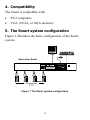
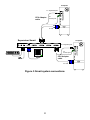
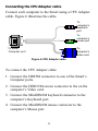
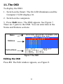
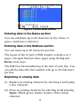
Supervisor Smart
4, 8 and 16 Port
User Guide
International HQ
North American HQ
European HQ
Italy
Jerusalem, Israel
Linden, New Jersey
Zurich, Switzerland
Rome
Tel: + 972 2 535 9666
Tel: + 1 908 4862100
Tel: + 41 1 455 6220
Tel: + 39 06 8209 7902
[email protected]
[email protected]
[email protected]
[email protected]
www.minicom.com
Customer support - [email protected]
5UM20111 V1 4/03
Table of Contents
1.
2.
3.
4.
5.
6.
7.
8.
9.
10.
11.
12.
13.
14.
15.
16.
17.
18.
19.
20.
21.
22.
23.
24.
Welcome
Introduction
Features
Compatibility
The Smart system configuration
The Smart models
Pre-installation guidelines
Connecting the Smart system
Connecting the CPU Adapter cable
Connecting the KVM console
Connecting the system to the power supply
Order of switching on
The OSD
Editing the OSD
Entering data in the Name section
Entering data in the Stations section
Replacing or erasing data
Configuring the Scan Setup window
Changing the Hotkey from Shift to Ctrl
Changing the Keyboard language
Setting Autoskip
Using the OSD HELP
Operating the Smart system
Operating the system with the OSD
Selecting a computer
Scanning computers
Closing the OSD
Operating the system with the front panel touch pads
Accessing the next computer
Accessing the previous computer
Setting the scan time
1
3
4
4
5
5
6
7
7
9
10
10
10
11
11
12
12
12
13
15
15
16
16
17
17
18
18
19
19
19
19
20
25. Scanning
26. End scanning
27. Settings mode
Making advanced adjustments
Replacing a computer
Keyboard settings when replacing a computer
Mouse driver settings when replacing a computer
Viewing the settings
Exiting the Settings mode
28. Technical specifications
2
20
20
21
21
21
22
22
23
23
24
1. Welcome
The Supervisor Smart system is produced by Minicom Advanced
Systems Limited.
Technical precautions
This equipment generates radio frequency energy and if not installed in
accordance with the manufacturer’s instructions, may cause radio
frequency interference.
This equipment complies with Part 15, Subpart J of the FCC rules for a
Class A computing device. This equipment also complies with the Class
A limits for radio noise emission from digital apparatus set out in the
Radio Interference Regulation of the Canadian Department of
Communications. These above rules are designed to provide reasonable
protection against such interference when operating the equipment in a
commercial environment. If operation of this equipment in a residential
area causes radio frequency interference, the user, and not Minicom
Advanced Systems Limited, will be responsible.
Changes or modifications made to this equipment not expressly
approved by Minicom Advanced Systems Limited could void the user’s
authority to operate the equipment.
Minicom Advanced Systems Limited assumes no responsibility for any
errors that appear in this document. Information in this document is
subject to change without notice.
No part of this document may be reproduced or transmitted in any form
or by any means, electronic or mechanical, for any purpose, without the
express written permission of Minicom Advanced Systems Limited.
© 2003 Minicom Advanced Systems Limited. All rights reserved.
Trademarks
PS/2 is a registered trademark of International Business Machines
Corporation. All other trademarks and registered trademarks are the
property of their respective owners.
3
2. Introduction
Access and control multiple computers from one Keyboard
Video Mouse (KVM) console with the Supervisor Smart
(Smart) system. The Smart comes in 4, 8 and 16 port
models. Connect up to 4 computers to the 4 port model, 8
to the 8 port model and 16 to the 16 port model.
3. Features
•
Hot-Swap - disconnect and reconnect computers
without rebooting
•
Scan-mode operation with variable time interval
•
Rack mountable for standard 19" racks
•
Operate the system using an On Screen Display (OSD)
or the front panel touch pads
•
Create multi-level cascade arrangements. For example
by cascading the Smart 16 Port model, connect up to
up to 256 computers in the system
•
The computers and the KVM console can be placed up
to 4.5m/14.8ft from the Smart
4
4. Compatibility
The Smart is compatible with:
•
PS/2 computers
•
VGA, SVGA, or XGA monitors
5. The Smart system configuration
Figure 1 illustrates the basic configuration of the Smart
system.
P110
SD
Supervisor Smart
Computer
On
Setting
Scan
Scan
STATION 1
STATION 2
STATION 3
STATION 4
Supervisor SMART
MINIC
M
Quattro
Computers
1-16
Figure 1 The Smart system configuration
5
1
0
6. The Smart models
Figure 2 illustrates the front panel of all Smart models.
Computer
On
Setting
Scan
Supervisor SMART
MINIC
Scan
M
1
0
Figure 2 Smart front panel
The Figures below illustrate the rear panels of the Smart 8
and 16 port units respectively.
SERIAL MOUSE
KB
POWER
PS/2 MOUSE
SCREEN
COMPUTER 5
COMPUTER 6
COMPUTER 7
COMPUTER 8
COMPUTER 1
COMPUTER 2
COMPUTER 3
COMPUTER 4
Figure 3 Smart 8 port rear panel
SERIAL MOUSE
POWER
KB
PS/2 MOUSE
SCREEN
COMPUTER 13
COMPUTER 14
COMPUTER 15
COMPUTER 16
COMPUTER 9
COMPUTER 10
COMPUTER 11
COMPUTER 12
COMPUTER 5
COMPUTER 6
COMPUTER 7
COMPUTER 8
COMPUTER 1
COMPUTER 2
COMPUTER 3
COMPUTER 4
Figure 4 Smart 16 port rear panel
6
7. Pre-installation guidelines
•
Switch off all computers, and Smart units
•
Place cables away from fluorescent lights, air
conditioners, and machines that are likely to generate
electrical noise.
•
Ensure that the distances between the computers and
the Smart, and between the KVM console and the
Smart, do not exceed 4.5m/14.8ft.
8. Connecting the Smart system
Connect the Smart system using CPU Adapter cables.
Figure 5 illustrates the Smart system connections.
7
Computer
To keyboard port
CPU Adapter
cable
To
mouse port
To Video card
Supervisor Smart
SERIAL MOUSE
POWER
KB
PS/2 MOUSE
SCREEN
Computer
COMPUTER 5
COMPUTER 6
COMPUTER 7
COMPUTER 8
COMPUTER 1
COMPUTER 2
COMPUTER 3
COMPUTER 4
P110
To keyboard port
SD
To
mouse port
CPU Adapter
cable
To Video card
Figure 5 Smart system connections
8
Connecting the CPU Adapter cable
Connect each computer to the Smart using a CPU Adapter
cable. Figure 6 illustrates the cable.
To
computer’s
keyboard
port
To
computer’s
mouse port
To Smart
‘Computer’ port
To
computer’s
Video card
Figure 6 CPU Adapter cable
To connect the CPU Adapter cable:
1. Connect the DB25M connector to one of the Smart’s
Computer ports.
2. Connect the HDD15M screen connector to the on the
computer’s Video card.
3. Connect the MiniDIN6M keyboard connector to the
computer’s Keyboard port.
4. Connect the MiniDIN6M mouse connector to the
computer’s Mouse port.
9
Connecting the KVM console
To connect the Smart to a KVM console:
1. Connect the monitor’s connector to the Smart’s Monitor
port.
2. Connect the keyboard’s connector to the Smart’s
keyboard port.
3. Connect the mouse’s connector to the Smart’s Mouse
PS/2 port.
9. Connecting the system to the power
supply
Connect the system to the power supply using the Power
adapter and cable provided.
10. Order of switching on
1. Switch on the Smart unit. The Computer # indicator
displays 01.
2. Switch on the computers.
Always switch on the Smart BEFORE switching on the
computers.
10
11. The OSD
To display the OSD:
1. Switch on the Smart. The On LED illuminates and the
Computer # LED displays 01.
2. Switch on the computers.
3. Press Shift twice. The OSD appears. See Figure 7.
There are 3 parts to the OSD. You can enter data in the
Name and Stations sections.
Nam e
Stations
Instructions
Figure 7 The OSD
Editing the OSD
Press F2. The Edit window appears, see Figure 8.
11
Figure 8 The Edit Mode window
Entering data in the Name section
You can substitute up to 60 characters in the 2 lines. A
space constitutes a character.
Entering data in the Stations section
You can insert up to 20 characters per line.
The layout of the 16 port’s OSD window extends over 2
pages. Navigate between these pages using the Up and
Down arrow keys.
The OSD has fixed numbering at the start of each line. You
can edit the data after this number with up to 20 characters
per line.
Replacing or erasing data
(i). Replace an existing character by selecting it and typing
a new character.
(ii). Erase an existing character by selecting it and pressing
Space. Blank spaces remain in place of the erased
character.
12
(iii).Erase a line of existing characters by navigating with
the cursor to the beginning of that line and pressing
Space. Keep Space depressed until the line is erased.
12. Configuring the Scan Setup window
Configure the scan function in the Scan Setup window as
follows:
1. Press F3. The Scan Setup window appears.
See Figure 9.
Figure 9 The Scan Setup window
Change the scanning period in the SCAN / SEC column.
Change the display period of a computer’s screen with the
OSD summary in the DISP/SEC column.
To set the above periods:
1. Place the cursor over one of the 3 digits and type a new
number.
13
Enter a leading zero where necessary. For example, type
040 for 40 seconds.
Typing 999 in column 3 gives you a display for a
continuous period of time.
2. Press Esc to save the changes and exit from the Scan
Setup window.
Note:
(i). Move within the Scan Setup window vertically, using
the Up and Down arrow keys.
(ii). When retyping a group of 3 digits, once you reach the
third digit of that group, the cursor automatically
reverts to the first digit.
(iii).Press Tab to move horizontally, on any line between
the first digit in the SCAN / SEC column and the first
digit in the DISP / SEC column.
(iv).You cannot use the Home or the End keys.
14
13. Changing the Hotkey from Shift to Ctrl
By pressing Shift twice, the OSD appears. You can replace
Shift with Ctrl.
To do so:
1. Press Shift twice. The OSD appears.
2. Press F3. The Scan Setup window appears displaying
the F9 hotkey definition as Shift Shift.
3. Press F9. The displayed definition of hotkey F9,
changes from Shift Shift to Ctrl Ctrl. The hotkey is
now Ctrl.
4. Press Esc or Enter. The OSD disappears. To display
the OSD in future press Ctrl twice.
To revert to the Shift key, repeat the above, substituting
Shift for Ctrl, and Ctrl for Shift.
14. Changing the Keyboard language
The keyboard is preset to US English, but you can
interchange between three languages - US English,
German, and French, as follows:
1. From the Scan Setup window, press F8. The KB
language changes from US English to German.
The displayed definition of hotkey F8, changes
from US to DE.
15
2. Pressing F8 twice changes the KB language from
US English to French. The displayed definition of
hotkey F8, changes from US to FR.
3. Press Esc or Enter. The OSD window disappears.
15. Setting Autoskip
To activate Autoskip:
1. Press Shift. The OSD window appears.
2. Press F3 key. The Scan Setup window appears
displaying F6 Autoskip as Off.
3. Press F6. The displayed definition of Autoskip F6,
changes from Off to On. Autoskip is now On.
16. Using the OSD HELP
To access the HELP window
Press F1. The HELP window appears, see Figure 10.
16
Figure 10 The HELP window
17. Operating the Smart system
You operate the Smart system through the OSD or using
the front panel touch pads.
18. Operating the system with the OSD
Press Shift twice. The OSD appears. See Figure 7 above.
The OSD’s operating functions include:
•
•
Selecting a computer
Activating and deactivating the Scan
17
Selecting a computer
To select a computer:
1. Press the Up or Down arrow keys.
2. Press Enter. The OSD window disappears, and the
selected computer’s screen appears. An OSD tag
appears on the screen showing which computer is
accessed. When the selected computer is switched off,
the screen appears dark.
(i). When Autoskip is On, all the active computers appear
in yellow letters. The arrow keys access only the active
computers.
(ii). When Autoskip is Off, The arrow keys access both
active and inactive computers.
(iii).Autoskip On is the default.
19. Scanning computers
After configuring the Scan Setup window, as explained
above, you can scan the computers.
To activate scanning:
•
•
Press Shift twice. The OSD appears.
Press F4. Your screen displays each active computer
sequentially, with the Scan label appearing in the top
left corner.
To deactivate scanning:
18
•
Press F4.
Or
•
Press Shift twice. The scan deactivates.
20. Closing the OSD
To close the OSD
Press Esc. The OSD closes.
21. Operating the system with the front
panel touch pads
The following operations can be carried out using the front
panel touch pads (as well as through the OSD).
22. Accessing the next computer
To access the next computer in the system:
Press
.
The next computer in the system is accessed.
23. Accessing the previous computer
To access the previous computer in the system:
. The previous computer in the system is
Press
accessed.
19
24. Setting the scan time
To set the scan time:
Scan
1. Press
. The current scan time is displayed on the
front panel.
2. Press
Press
to increase the scan-time.
to decrease the scan-time.
With the touch pads you can increase or decrease the scantime by 15, 30, 45, 60, 75, 90 seconds, and 2, 3, 4, and 5
minutes.
25. Scanning
To start scanning:
Scan
Press
. The Scan light on the front panel illuminates
and the scanning activates.
26. End scanning
To end scanning:
Press
Scan
. Scanning ends.
20
27. Settings mode
Enter the Settings mode to:
•
Make advanced adjustments
•
View settings
To enter the Settings mode:
Press Shift then, F2. Release Shift before pressing F2.
Making advanced adjustments
The Smart operates with:
•
Windows, Linux, Novell or UNIX systems
•
2 or 3 or 5 button PS/2 mouse, Intellimouse or
Wheel mouse
When connected and switched on as set out above, the
Smart automatically operates with the computer and mouse
types connected to it.
Replacing a computer
When a computer is replaced with a different computer
type while the Smart is in use, we recommend turning the
new computer off before connecting it to the Smart.
When turning the computers off is inconvenient, do the
following:
21
In the Settings mode adjust the Smart keyboard and mouse
modes to be compatible with the new computer. See the
tables below.
Keyboard settings when replacing a computer
For
Type the letters
PC (Windows, Linux, Novell)
PC
UNIX console mode
UC
UNIX graphics mode
UG
Set the keyboard mode setting to:
•
PC when operating Intel based computers.
•
UC when operating UNIX computers in console
mode.
•
UG when operating UNIX computers in graphics
mode.
Mouse driver settings when replacing a computer
For
Type the letters
Wheel mouse or Intellimouse
IN
2 or 3 button mouse
PS
5-button mouse
EP
22
Set the mouse setting to IN when the computer has an
operating system that supports Wheel mouse functionality:
(Windows 98 and Linux*).
Set the mouse setting to PS when the computer has an
operating system that does not support Wheel mouse
functionality: (Windows 95, NT4, DOS, Linux*, UNIX
and Novell).
*Depending on the version.
Set the mouse setting to EP when the computer has an
operating system that supports Explorer mouse
functionality: (Windows – ME, 2000, and XP).
Viewing the settings
View the settings and firmware revision in any text editor.
To view the settings:
1. Before entering to the Settings mode switch the
keyboard layout to English.
2. Open any text editor, e.g. Notepad.
3. Press Shift, followed by F2 to enter the Settings mode.
4. Press F. The settings appear in the text editor.
Exiting the Settings mode
To save changes and exit the Settings mode:
Press Esc.
23
28. Technical specifications
Video
Interface
Resolution
Transmission
distances
Video
Signal
Analog signal Red Green
Blue 0.7Vp-p/75 Ω positive
Sync
TTL compatible
Horizontal
Sync. positive/negative
Vertical
Sync. positive/negative
Monitor
Up to 1280 x 1024 pixels
Horizontal
frequency
30-100 KHz
Vertical
frequency
43-100 Hz
From KVM to Smart 4.5m/14.8ft
From computer to Smart 4.5m/14.8ft
Dimensions
Smart 8 port
44.5mm x 430 mm x 180 mm
1.8 " x 16.9 " x 7.1 "
Smart 16 port
81mm x 430 mm x 180 mm
3.20 " x 16.9 " x 7.1 "
Power supply
Smart 8 port
AC adapter: 220/9V 2A; 110/9V 2A
Smart 16 port
AC adapter 100-240V 0.4A
24
Operating
temperature
0ºC to 40ºC/32ºF to 104ºF
Storage
temperature
-40ºC to 70ºC/-40ºF to 158ºF
Humidity
80% non-condensing relative humidity
25
26