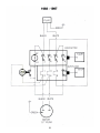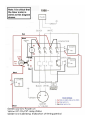
1
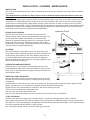
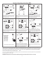
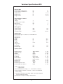
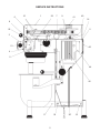
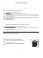
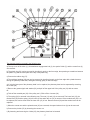
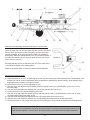
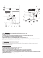
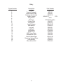
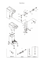
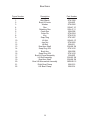
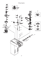
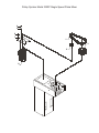
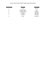
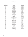
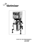
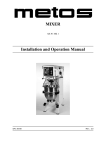
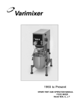
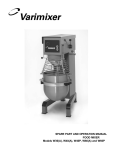
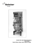
FOOD MIXER
SPARE PART AND OPERATION MANUAL
June 2012
Form 103
Model W20 A, J, F
1993 to Present
Caution
-READ BEFORE OPERATING-
Caution
Varimixer recommends that mixer operators be at least 18 years of age and be thoroughly trained
on the use of the mixer.
Varimixer recommends that the following precautions be adopted to help make the mixer operation
safer and more efficient.
........- All operators should be at least 18 years of age.
- All operators should be thoroughly trained before being allowed to operate the mixer.
- NEVER reach into the bowl when the mixer is running.
- Do not wear loose clothing or rings while operating the mixer.
- Stop the mixer and lower the bowl before adding ingredients, scraping the bowl, removing the
............agitator, or removing the product.
- Stop the mixer before removing or installing attachments into the drive hub.
- Do not attempt to assemble or disassemble attachments while mounted into the drive hub.
- Always use the pusher plate with the slicer/meat grinder attachments.
- NEVER bypass the safety mechanisms supplied on the mixer. Doing so can cause injury and
............is the responsibility of the user to insure these safety mechanisms are operating properly.
LIMITED WARRANTY
Varimixer warrants its commercial mixers to the original purchaser against defects in material or manufacture for a period of one
year from the date of original purchase, subject to the following exclusions and limitations. The warranties provided by Varimixer
do not apply in the following instances:
EXCLUSIONS
1. In the event that the equipment is improperly installed. Proper installation is the responsibility of the installer, proper installation
procedures are covered in the Varimixer Spare Parts and Operations Manual.
2. In the event that the equipment is improperly maintained. Proper maintenance is the responsibility of the user. Proper maintenance procedures are covered in the Varimixer Spare Parts and Operations Manual.
3. In the event that failure or malfunction of the appliance or any part thereof is caused by abnormal use or is otherwise not attributable to a defect in material or manufacture.
4. In the event that the appliance , by whatever cause, has been materially altered from the condition in which it left the factory.
5. In the event that the rating plate has been altered or removed.
6. On parts which would normally be worn or replaced under normal conditions.
7. With regard to adjustments and/or calibrations. Checking of and changes in adjustments and calibrations are the responsibility of
the installer, Proper installation is the responsibility of the installer, proper installation procedures are covered in the Varimixer
Spare Parts and Operations Manual.
If any oral statements have been made regarding the appliance, such statements do not constitute warranties and are not part of the
contract of sale. This Limited Warranty constitutes the complete, final and exclusive statement with regard to warranties.
..THIS LIMITED WARRANTY IS EXCLUSIVE AND IS IN LIEU OF ALL OTHER WARRANTIES WHETHER..
WRITTEN, ORAL OR IMPLIED, INCLUDING, BUT NOT LIMITED TO, ANY WARRANTY OF..MERCHANTABILITY
OR FITNESS FOR PARTICULAR PURPOSE OR WARRANTY AGAINST LATENT...DEFECTS.
LIMITATIONS OF LIABILITY
In the event of warranty claim or otherwise, the sole obligation of Varimixer shall be the repair and/or replacement at the option of
Varimixer, of the appliance or component or part thereof Such repair or replacement shall be the expense of Varimixer except that
travel over 100 miles or two hours, overtime, and holiday charges shall be,, the expense of the purchaser. Any repair or replacement
under this warranty does not constitute an extension of the origin, warranty for any period for the appliance or for any component
part thereof. Parts to be replaced under this warranty will be repaired or replaced at the option of Varimixer with new or functionally
operative parts. The liability of Varimixer on any claim of any kind, including claims based on warranty, expressed or implied, contract, negligence, strict liability or any other theories shall be solely and exclusively the repair or replacement of the product as stated
herein, an such liability shall not include, and purchaser specifically renounces any rights to recover, special, incidental, consequential or other damages of any kind whatsoever, including, but not limited to, injuries to persons or damage to property, loss of profits
or anticipated profits, or loss of use of the product.
TO SECURE WARRANTY SERVICE
If you claim a defect covered by this Limited Warranty, first direct your claim to the local Authorized Service Agency, giving model,
serial and code numbers, voltage, a description of the problem and your sales slip. If this procedure fails to be satisfactory to you,
you may write to the Varimixer National Service Manager, 14240 South Lakes Drive, Charlotte, NC 28273; you should include the
information listed above.
TABLE OF CONTENTS
Installation Instructions...................................................................................................2
Cleaning Instructions.....................................................................................................2
Operating Instructions....................................................................................................3
Specifications......................................................................................................4
Service Instructions.........................................................................................................5
Main Body.....................................................................................................................11
Bowl Arms.....................................................................................................................13
Pulley System................................................................................................... ..........15
Planetary Head.............................................................................................................17
Attachment Drive..........................................................................................................19
Front Control Panel/ Electrical Components.................................................................21
Bowl Screen..................................................................................................................25
Tools and Bowls............................................................................................................27
Electrical Diagrams.......................................................................................................29
1
INSTALLATION - CLEANING - MAINTENANCE
INSTALLATION:
The mixer can be placed directly on the floor. Foundation bolts in the floor are necessary only under special conditions,
e.g. in ships.
If the 20-quart mixer is placed on a bench stand, it must be fastened with the bolts that fasten the unit to the
shipping pallet.
Ensure that the voltage, phase and hertz printed on the identification plate of the mixer are the same as that at the place
of installation. The identification plate is located at the top of the right side of the mixer. Be sure the mixer is properly
connected to the incoming power supply and the ground or earth connection is made. The arrow on the front of the
planetary head (see drawing 2, page 1), indicates the direction of rotation of the planetary head. On three-phase motors
the direction of rotation can be changed by interchanging two phases of the connecting cable or the motor. Electrical
connections must be made in accordance with local regulations.
DOUGH HOOK CLEANING:
Special care should be given to cleaning the dough hook. The
Varimixer dough hook is manufactured of stainless steel and we recommend that it be cleaned and sanitized in a commercial dish
machine. An alternate cleaning procedure is to vigorously scrub the
dough hook with a hot water and detergent solution. Use a heavy
bristled brush. After cleaning, sanitize the dough hook by rinsing with
a 50 ppm solution of sodium hypochlorite.
Lubrication Points
CLEANING:
The mixer should be cleaned daily or after use. Wash with a soft
brush and pure water. Synthetic detergents should be used with care
as they destroy the lubricants of the mixer. Washing with a hose is
not recommended. Bowls and mixing tools should be washed in
detergents which do not attack aluminum. Detergent suppliers will be
able to recommend the right type.
LUBRICATION AND MAINTENANCE:
When the mixer is used regularly, the varispeed system must be
lubricated approximately once each month. When the mixer is extensively used, or used often without changes in speed, lubrication intervals should be shorter.
DIRECTIONS FOR LUBRICATION:
Start the mixer and increase the speed to approximately 50%. Stop
the mixer and remove the top cover by removing the two screws (2),
see page 2-3.
A grease nipple is located at the top of each of the pulley sets. Press the grease through the grease nipples until the
grease gun feels hard, or until grease is pressed out between the shaft and the pulleys.
Replace the top cover and remember to replace the two screws securing the cover.
The lid must be mounted before starting the mixer.
Start the mixer and set the speed back to low.
Stop the mixer and fill the grease gun with new grease to be prepared for the next lubrication.
TYPES OF GREASE:
Grease for the shafts of the pulley sets: Lubriplate 1200-2, or another ball bearing grease: NLGI1 or NLGI 2.
When repairing the planetary head (which is greased for life) the grease (PN 868VH) should be used in the gear wheel,
gear wheel rim. The needle bearings of the planetary head should be greased with PN Sapphire 2 The needle bearings
must not be greased with the PN 868 VH type of grease.
Use only this type grease and do not mix with other types of grease.
2
Varimixer Operating Instructions W20
Place the bowl in the bowl arms. Be sure
that the bowl is placed correctly and the
bowl clamps are used.
Place the mixing tool in the bayonet shaft.
The pin of the tool must be turned into the
bayonet hole.
Set the time required by turning the timer to Start the mixer by pressing the green start
the right. The mixer will stop automatically button. The mixer will only start with the
when the time runs out.
timer on and the bowl screen closed.
Raise the bowl to working position by pulling the handle forward. Ensure that the
bowl is placed correctly while the bowl is
lifted. Close the bowl screen.
Push the speed selector lever to obtain
the required speed. The speed must be
changed only when the mixer is running.
Dough Hook
100 R.P.M.
Flat Beater
250 R.P.M
Wire Whip
400 R.P.M.
Recommended maximum speeds
Before the mixer is stopped, the speed
selector lever should be moved to the lowest speed. The mixer must not be started
when loaded in high speed position.
Stop the mixer by pressing the red stop
button.
OVERLOADING: Do not overload the mixer. Tough and heavy doughs might reduce the working capacity of the mixer by 75%. The
capacity will be further reduced if the speed of the tool is increased beyond what is recommended, or if a wrong tool is used. Big
lumps of grease or cooled ingredients must be divided into fine particles before being placed into the bowl. A long period of overloading will cause the thermal overload relay to stop the mixer. Let the mixer rest for approximately three minutes and press the RED
STOP button BEFORE pressing the GREEN START
button.
If the mixer is stopped in high speed when loaded, the bowl is to be removed from the mixer and the speed set to low speed before
the bowl is placed in the mixer again.
WARNING: Bodily harm could result from placing hands into the bowl while the mixer is running.
3
Varimixer Specifications W20
Dimesion Data
Level Capacity of large bowl
Level Capacity of small bowl
Width Overall
Depth Overall
Height Overall
Qt.
Qt.
In.
In.
In
Electrical Data for Motor**
60HZ / 1 Phase
Voltage*
Feed Wires incl. Ground
Motor Power
Amperes,full load
V115
No.
3
HP
1
A
12
Mixing Speed
Agitator Speed
Agitator Speed
Attachment Hub
Min.
Max.
R.P.M.
2 1
1 3
17 7/8
26 1/2
34 7/8
100
400
90-420
Shipping Data
Basic Machine plus 1 s/s bowl,1 set of standard tools
Measurement
Shipping Box
Width
In.
28 ½
Depth
In.
30 ½
Height
In.
46 ½
Volume
Cu.Ft.23.4
Weight Data
Net Weight
Lbs.
196
Gross Weight
Lbs.
233
Capacity Chart
Mashed Potatoes
Whipped Cream
Muffins
Layer Cake
Pie Dough
Pancake Batter
Cookie Dough
Donuts,Yeast
Donuts,Cake
Bread Dough (65% AR)
Pizza Dough (50% AR)***
Whip or Beater
Whip
Beater
Beater
Pastry Knife
Whip or Beater
Beater or Hook
Hook
Beater
Hook
Hook
%AR= weight of water
weight of flour
*On the nominal motor voltage + or – 10% tolerance is allowed.
**Also available in 220/60/1 , 220/50/1 , 110/50/1. Not submitted
for UL listing.
***Varimixer also features our Model W20P , specifically designed
for pizza and pretzel dough.
Specifications are subject to change without notice.
4
17
4
24
23
21
9
14
20
23
25
12
lbs.
Qts.
lbs.
lbs.
lbs.
Qts.
lbs.
lbs.
lbs.
lbs.
lbs.
SERVICE INSTRUCTIONS
6
10
22
1
7
9
40
41
16
8
2
55
3
21
43
4
5
44
42
18
17
5
20
19
SERVICE INSTRUCTIONS
(1) Remove the top cover of the mixer (1) and the plastic cover (43) by removing the 2 screws
(3) The attachment engagement hub is taken out by removing the plastic cover (4) and the 4 bolts (5).
(6) The control box is taken off by removing the 2 screws (55).
(7) The special V-belt is replaced in the following way:
a) Remove the top cover of the mixer (1) and the plastic cover (43).
b) Press the speed selector lever (8) back toward the back of the mixer so that the special V-belt is loosened,
and take off the special V-belt.
c) The special V-belt is mounted by first placing it on the rear pulley set (9) (the motor pulley set) and opening
the pulleys by pulling the special V-belt.
d) Turn the speed selector lever (8) back toward the back of the mixer (high speed) and mount the special
V-belt on the front pulley set (10).
e) Adjust the speed (see page 8).
(9) The motor pulley set is taken off in the following way:
a) Remove the top cover of the mixer (1), the plastic cover (43), the special V-belt (7)
b) The motor pulley set can now be taken off by loosening the~ 2 screws (40).
The upper half of the pulley set can be taken off by removing the circlip (41).
(21) Relay and thermal overload relay are taken out in the following way:
a) Remove the top cover of the mixer (1), the plastic cover (43), the special V-belt (7), and the control panel
(6).
b) Loosen the screws (22).
c) If the relay is to be replaced, the screw (57) is removed.
Before relay and thermal overload relay are taken out, the mixer must (for safety reasons) be disconnected on the
main switch or the connecting cable disconnected.
The indicator (23) on the side of the thermal overload relay is adjusted to the rated current of the motor + 10%.
(42) The motor is removed in the following way:
a) Switch off the voltage to the mixer or disconnect the connecting cable.
b) Remove the top cover of the mixer (1), the plastic .....
.cover (43), the special V-belt (7), and the motor pulley set (9).
c) Remove the motor cable from the connecting box (44) of the
motor.
d) Place the mixer on its back.
e) Remove the legs of the mixer (17) and the bottom plate (19).
f) The motor can be pulled out backwards by removing the 4
bolts (16)
6
57
22
23
The planetary head is removed in the following way:
a) The top cover of the mixer (1), the attachment engagement hub (3), the special V-belt (7), and the control box (6)
are removed.
b) The plastic ring (26) can be removed by knocking it gently on the front edge, then pressing a screwdriver between
the plastic ring and the metal plate at the top of the plastic ring.
c) Remove the rubber ring (27).
d) The stainless headcap (28) can now be removed by knocking it gently on the front edge with a plastic hammer,
turning the planetary head 1800, and again knocking gently on the front edge.
e) If only the lower part of the planetary head is to be repaired, the planetary head can be separated by removing
the 3 bolts (29).
f) Remove the grease nipple and washer (30), and pull off the upper half of the pulley set (31) with an extractor.
g) Take off the movable part (32) of the pulley set. h) Take off the 4 screws (33).
h) The spring (34) is removed in the following way: The nuts (11) and (12) are removed. The lower fork (15), the
toothed rack (35) and the spring (34) will come up also when the nut (12) is removed. If the toothed rack (35) is to
be replaced, this can be done when the lower fork (15) is free. Remove the bolt (38) and the toothed rack can be
replaced.
i) When the counter nut and the pointed screw (36) are removed, the speed selector lever (8) can be removed.
k) Remove the pin bolt (37) by loosening the counter nut.
I) By loosening and removing the 4 bolts (25), the planetary head can be lowered.
7
9
B
C
See Drawing
A
16
8
39
35
32
15
34
7
11
Mounting of the planetary head should be done in reverse order.
12
When the lower fork (15) and the spring (34) are mounted, the speed
selector lever (8) is turned counter clockwise, so that it points horizontally backward, at the same time as the lower fork is pressed
down gently. When the speed selector lever (8) is turned clockwise, it
will catch the toothed rack (35) and pull down the lower fork. Screw
on the nuts (11) and (12).
Drawing A
38
Be aware that the pin (39) on the lower part (32) of the pulley set is
to be placed as shown in the drawing above.
When all parts have been mounted, the speed must be adjusted.
14
15
13
Adjustment of speed and belt
a) Adjust the distance (8) 12.6", by loosening the 4 bolts (16) and moving the motor back and forth. The tolerance of the
.....distance (B) can be used in cases where there are problems in adjusting the speed correctly, as the distance (B) is
.....dependent on the tolerance of the special V-belt.
b) Loosen the lock nut (11) and the adjusting nut (12).
c) Start the mixer and adjust the lowest speed so that the special V-belt (7) is approximately 1/16 to 1/8" (C) from
.....the pulley edge.
d) Stop the mixer and tighten the adjusting nut (12) loosely and then the lock nut (11)
e) Loosen the lock nut (13) and the adjusting screw (14).
f) Start the mixer and adjust the highest speed so that the special V-belt (7) is approximately 1/16 to 1/8" (C) from
the pulley edge of the motor pulley set (9).
g) Stop the mixer and tighten the adjusting screw (14) loosely and then the lock nut (13).
h) Start the mixer and control the measure (C) on both pulley sets at high and low speed, respectively.
i) Be aware that the pin (39) on the lower part (32) of the pulley set is to be placed as shown on the drawing above.
Tolerances in the transmission can cause the special V-belt (7) to hit the pins of the pulley sets when the
speed has been adjusted. In these cases, the distance (B) is to be reduced and the speed readjusted.
8
50
52
51
50
53
54
D
47
56
46
48
45
49
45
17
18
20
19
(45) The bowl arms are to be replaced in the following way:
a) Disconnect the mixer on the main switch or disconnect the connecting cable.
b) Lower the bowl arms.
c) Place the mixer on its back and remove the legs of the mixer (17) by removing the screws (18).
d) The bottom plate (19) is removed by removing the nuts (20).
e) Remove the cotter pin (51), securing the lifting bolt (46) and the lifting nut (47).
f) Remove the lifting bolt (46) and the lifting nut (47).
g) Remove the 2 circlips (48) from the 2 bowl arm guide rods (49); then the bowl arm guide rods (49) can be knocked
back so that the bowl arms are free and can be removed.
(50) The lifting lever is replaced in the following way:
a) Begin as described above from a) to f) inclusive.
g) Remove the crank shaft (52) by removing the circlip (56). h) Ensure that the key (53) has also been removed.
i) Remove the lifting lever (50).
Adjustment of bowl height
a) Lower the bowl arms.
b) Loosen the counter nut (54) and remove the cotter pin (51).
c) Remove the lifting bolt (46) and the lifting nut (47).
d) Adjust the bowl height by turning the lifting nut (47) either out or in, on the lifting bolt (46).
e) Mount the lifting bolt with the lifting nut and the cotter pin, and tighten the counter nut (54).
f) Ensure that the measure (0) 5" is correct when the bowl is raised to normal working position, and repeat the procedure
if the measure is not correct.
g) Ensure that all mixing tools are fitting in the bowl.
9
Notes:
10
Body
11
Body
Figure Number
1.
2.
3.
4.
5.
6.
7.
8.
9.
10.
11.
12.
13.
14.
15.
16.
17.
18.
19.
20.
21.
Description
Screw
Top Lid (Painted)
Rear Access Plate
Bushing (Lift Handle)
Upper Column
Plug Button
Bushings
Column Seal
Plug Button
Lower Column
Bolt M8X20
Leg Left
Leg Right
Plug Button
Rubber Foot
NSF Cover Plate
Suspension Hook
Column Base Plate
Retaining Spring f/Plate
Lock Nut M6
Mixer Mount Bolt
12
Part Number
STA 5233
20D-21
20N-291
STA 2515
20N-22.17
STA
6561
STA 2514 (each)
20N-207
STA 6511
20N-22.30
STA 5631
20N-25.1
20N-25.2
STA 6560
20N-218
20N-304
20N-302
20N-22.35
20N-310
STA 5831
STA 5441
Bowl Arms
M
Bowl Arms
Figure Number
1.
2.
3.
4.
5.
6.
7.
8.
9.
10.
11.
12.
13.
14.
15.
16.
17.
18.
19.
20.
21.
22.
Description
Part Number
Ball (Black)
Bowl Lift Lever
Washer
Disc
Retaining Disc
Crank Arm
Cotter Pin
Key
Snap Ring
Lift Nut
Jam Nut
Lift Bolt
Bowl Arm Shaft
Snap Ring 25U
Bowl Arm
Snap Ring 25U
Bowl Lift Lever Assembly
Lift Bolt Assembly
Bowl Arm Shaft
Bowl Lift Microswitch Assembly
Right Bowl Clamp
Left Bowl Clamp
STA 3306
20N-62Z
STA 6066
20N-47.10
20N-47.11
20N-63M
STA 6204
STA 2019
STA 3407
20N-65.1Z
STA 5825
20N-83.1
20N-68.1M
STA 3410
20N-23M
STA 3410
20N-62Z
20N-65.1M
20N-68.1M
56RN20-15
20N-23.5
20N-23.4
14
Pulley System
8
9
16
39
13
33
2
14
6
19
24
27
29
12
18
25
7
27
32
1
12
31
5
3
10
34
23
20
4
30
21
40
22
27
28
35
26
38
15
37
36
Pulley System
Figure Number
1.
2.
3.
4.
5.
6.
7.
8.
9.
10.
11
12.
13.
14.
15.
16.
17.
18.
19.
20.
21.
22.
23.
24.
25.
26.
27.
28.
29.
30.
31.
32.
33.
34.
35.
36.
37.
38.
39.
40.
Description
Part Number
Belt
Grease Nipple
Bolt M6x16
Motor Mount Plate
Bolt 3/8-16 X 3/4
Washer
Motor Pulley Pin
Grease Nipple
Snap Ring
Set Screw
-----------Bushing
Rubber Ring
Spring
-----------Spring Holder
-----------Pulley Pin
Motor Sliding Vari-Pulley
Bearing
Fork Ring
Motor 115v1 1HP
Snap Ring
Bolt
Bolt
Set Screw
Nut
Nut
Washer
Pin Bolt
Fronk Fork
Fork Tension Spring
Upper Pulley Assembly
Lower Pulley Assembly
Speed Lever
Thrust Spring
Thrust Pad
Thrust Washer
Motor Pulley Assembly
Tooth Rack
20-91
STA 3220
STA 5432
20N-61
STA 5442
STA 6018
60-285
STA 3220
STA 3410
STA 5604
-----------STA 2505
20N-228
20N-275
-----------20N-227
-----------20-285
20N-15M
15-103
15-17
20N-85.63
STA 3407
STA 5451
STA 5452
STA 5601
STA 5812
STA 5819
STA 6028
20N-305
20N-16.1
20N-16.5
20N-38M
20N-39M
20N-47M
20N-400
20N-47.20
20N-47.10
20N-13M
20N-46
16
Pulley System Model W20P Single Speed Pizza Mixer
4
5
6
7
1
3
2
8
Pulley System Model W20P Single Speed Pizza Mixer
Figure Number
Description
Part Number
1.
2.
3.
4.
5.
6.
7.
8.
Belt
Motor Pulley
Planetary Pulley
Bolt 3/8-16X3/4
Washer
Bolt M6X16
Washer
Motor
20P-91
6J19
6J60
STA 5442
STA 6009
STA 5432
STA 6008
20N-85.63
Planetary Head
1
2
3
4
5
6
7
8
12
13
9
14
15
10
16
20
17
11
21
18
22
19
23
24
25
26
27
28
29
30
31
32
20N-2.1Z
20N-3
20N-2
20N-2.1M
33
34
35
20-36
20N-30
20-33
20N-101
17
Planetary Head
18
Figure Number
Description
Part Number
1.
2.
3.
4.
5.
6.
7.
8.
9.
10.
11.
12.
13.
14.
15.
16.
17.
18.
19.
20.
21.
22.
23.
24.
25.
26.
27.
28.
29.
30.
31.
32.
33.
34.
35.
Snap Ring
Bearing 6206
Snap Ring
Bolt M6X16
Main Bearing Head
Snap Ring
Bearing 6206
Distance Piece
Gear Wheel Rim
Bolt M8X30
Main Shaft
Snap Ring
Eccentric Disc
Bearing 6006
Snap Ring
Snap Ring
Seal
Needle Bearing Race
Groove Pin
Needle Bearing set
Disc
Upper Rim Pinion
Lower Rim Pinion
Eccentric Head
Needle Bearing
Bolt
Distance Piece
Bearing 6205
Distance Piece
Snap Ring
Key
Bayonet Shaft
Stainless Cover
Black Cover
Rubber Ring
STA 3414
20-98
STA 3518
STA 5432
20N-3
STA 3518
20-98
20-37
20N-1
STA 5626
20N-30
STA 3470
20-36
20-100
STA 3515
STA 3414
20N-108R
See item 25
STA 6460
20-96
20-235
20-31
20-32
20N-2
20N-101
STA 5641
20-34
20-97
20-34
STA 3514
STA 2008
20-33
20-272
20++-272.1
20-209
Attachment Drive
9
ixer
R
VaBrim
EA
OP
ST
T
AR
ST
1
2
3
4
5
6
7
10, 10A
8, 8A
16
11,11A
9
17
12
15
13
14
2î
2” I.D.
I.D.
1 ½”
Ω ì I.D.
I.D.
20N-10.5M
#17 Hub
20N-10.6M
#12 Hub
19
Attachment Drive
Figure Number
1.
2.
3.
4.
5.
6.
7.
8.
8A
9.
10.
10A.
11.
11A.
12.
13.
14.
15.
15A
16.
17.
Description
Part Number
Snap Ring
Wormwheel
Snap Ring
Bearing
Distance Piece
Bearing
Key
Shaft F/ #17 Hub
Shaft F/ #12 Hub
O-ring
Hub F/ #17 (2” I.D.)
Hub F/ #12 (1 1/2” I.D.)
Thumb Screw F/ #17 M10 x1.5
Thumb Screw F/ #12 M8 x 1.5
Hub Ring
Lock Washer
Bolt
Cover F/ #17
Cover F/ #12
Snap Ring
Hub Pin
STA 3410
20N-9
STA 3512
15-105
20N-37
15-105
STA 2031
20N-50
20J-50
STA 3127
20N-8
20J-8
STA 5561
4R-125
20N-211
STA 6038
STA 5631
15-214
312C
STA 3512
STA 6316
20
Electrical Components 1993-mid 1997
21
Electrical Components 1993-mid 1997
Figure Number
Description
Part Number
1.
2.
3.
3A
4.
5.
6.
7.
8.
9.
10.
11.
12.
13.
14.
15.
16.
17.
Front Panel No Hub
Front Panel w/Hub
Front Foil No Hub
Front Foil w/ Hub
Stop Button Complete
Start Button Complete
Timer Assembly 115V
Timer Knob
Timer Screw(s)
Timer Scale
Screw
C Plate for Switch
Screw for Bracket
Screw
Thermal Overload 11-16
Auxiliary Switch
Contactor 110V 16 A
Contactor Bracket
No Longer Available*
No Longer Available**
No Longer Available
No Longer Available
30-175
30-174
20-188.15M
30-189
STA 5121
30-190
STA 5230
20N-176.5
STA 5230
STA 5230
20-88.24
20-88.45
100-88.4
20N-151
* Unit must be retrofitted with new style Front panel assembly (PN 20N-650.3M
No Hub)and contactor bracket (PN 20N-151.2)
** Unit must be retrofitted with new style Front panel assembly (PN 20N650.8M w/Hub)and contactor bracket (PN 20N-151.2)
22
Electrical Components 1998-Present
3, 3A
23
Electrical Components 1998-Present
Figure Number
1.
2.
3
3A.
4.
5.
6.
6A.
7
7A.
8.
9.
10.
11.
12.
13.
14.
15.
16.
17.
18.
19.
Description
Start Switch Assembly
Stop Switch Assembly
Timer Assembly 115V
Internal Timer 3-3000 Sec 110V
(for McDonald's)
Timer Knob
Timer Scale
Front Panel Assembly No Hub
Front Panel Assembly Hub
Front Foil w/ Hub
Front Foil w/o Hub
Motor Cable Grommet
Tension Relief
Screw
Screw
Contactor Bracket
Auxiliary Switch
Contactor 110V 16 A
Thermal Overload 11-16
Screw
Motor Mount Plate
Bolt
Washer
24
Part Number
31-174.2
31-174.3
20-188.15M
WN20-188.1
30-189
30-190
20N-650.3M
20N-650.8M
20N-149.1.2
20N-149.1.1
STA 3000
STA 3002
STA 5851
STA 5232
20N-151.2
20-88.47
100-88.4
20-88.24
STA 5232
20N-61
STA 5432
STA 6008
Bowl Screen
2
3
4
10
8
11
6
5
9
56SN20-30
7
12
13
1
14
15
16
18
17
25
Bowl Screen
Figure Number
Description
Part Number
1.
2.
3.
4.
5.
6.
7.
8.
9.
10.
11.
12.
13.
14.
15.
16.
17.
18.
Bowl Screen Kit
Bushing
Cam
Set Screw
Screw
Microswitch
Set Screw
Cam
Spacer
Bolt
Nut
Bushing
Bracket Assembly
Nut
Bolt
Rear Screen
Front Screen
Chute
225/20N
56SN20-21.1
56SN20-21
STA 5664
STA 5251
56SN20-30
STA 5664
56SN20-22.1
56SN20-24
STA 5850
STA 5816
56SN20-21.1
56SN30-13
STA 5850
STA 5360
225/20NR
225/20NF
56G20-280
26
Tools and Attachments
27
Tools and Attachments
Figure Number
Description
Part Number
1.
2.
3.
4.
5.
6.
7.
8.
12.
13.
16.
19.
20.
21.
21A
22.
22A
23.
23A
24.
25.
26.
S/S Bowl 20Qt
S/S Bowl 12Qt.
S/S Bowl 25Qt.
S/S Hook 20Qt.
S/S Hook 12Qt.
Flat Beater 20Qt.
Flat Beater 12Qt.
S/S Flat Beater 20 Qt.
Wire Whip 20 Qt.
Wire Whip 12 Qt.
S/S Wing Whip 20 Qt.
Pin
Rack
Bowl Scraper 20 Qt.
Bowl Scraper 12 Qt.
Arm W / Blade 20 Qt.
Arm W / Blade 12 Qt.
Nylon Blade 20 Qt.
Nylon Blade 12 Qt.
Scraper Holder
Bolt
Washer
203/20N
203/12N
203/20C
213/20A
213/12N
205/20A
205/12N
204/20A
207/20A
207/12N
209/20A
STA 6259
222
224/20A
224/12N
42R20-102
42RN12-102
42R20-204
42RN12-204
42R20-101M
STA 5648
STA 6020
28
29
30
Notes:
14240 South Lakes Drive
Charlotte, NC 28273
(800) 222-1138
www.varimixer.com