1
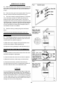
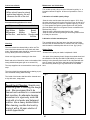
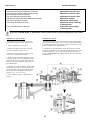
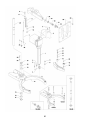
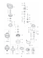
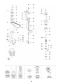
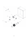
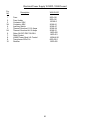
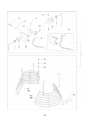
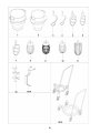
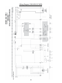
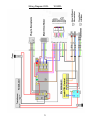
SPARE PART AND OPERATION MANUAL
Form 109 (09/10)
FOOD MIXER
Model W150PL
1993 to Present
TABLE OF CONTENTS
W150PL
Installation Instructions.................................................................................................43
Operating Instructions...................................................................................................44
Cleaning-Maintenance..................................................................................................45
Belt Adjustments and Removal.....................................................................................46
Adjusting the Bowl Clamping........................................................................................47
Capacity Chart................................................................................................................9
Machine Column......................................................................................................48-49
Bowl Arms/Microswitches........................................................................................50-53
Planetary Head........................................................................................................54-55
Transmission...........................................................................................................56-57
Speed Lever Assembly............................................................................................58-59
Instrument Panel/Power Supply...............................................................................60-63
Bowl Screen.............................................................................................................64-65
Accessories.............................................................................................................66-67
Electrical Diagrams..................................................................................................68-71
42
Read this page entirely BEFORE beginning installation.
VARIMIXER INSTALLATION INSTRUCTIONS
UNDER NO CIRCUMSTANCES ARE THE SPEED LEVER, BOWL LIFT LEVER, OR THE BOWL
ARMS TO BE USED TO MOVE THE MIXER INTO PLACE. DAMAGE WILL RESULT TO THE UNIT.
IT IS RECOMMENDED THAT THE TOP LID BE REMOVED BEFORE MOVING THE UNIT.
The mixer must be mounted with the rubber feet, which neutralize both shaking and rusting. Spacers
can be inserted under the mixer’s feet if the floor is uneven. The mixer can be bolted to the floor if d
esired.
Before the mixer is connected to power, it should be checked that the voltage and frequency on the
rating plate is correct in relation to the place of installation. A unit labeled 220V 3 Phase will operate
from 208V to 240V 3 phase safely. The rating plate is located on the rear right side of the mixer. The
electrical connection box is located at the top rear of the mixer.
WARNING
Electrical and grounding connections must comply with applicable portions of the National Electrical
Code and/or other local electrical codes................................................................ire
Wire Color Codes
White-Phase 1
Red -Phase 2
Black-Phase 3
Green-Ground
No Neutral is used in the United States and Canada
1. Lower the bowl using the bowl lift lever or the
bowl lift switch on the front panel.
4. Close bowl screen and raise
the bowl arms into the up
position.
2. Open the bowl screen. 3. Remove the bowl
and tools.
5. Turn timer to 10 minutes and
push “start” .
43
6. Insure cover is rotating in
the correct direction.
OPERATION OF THE MIXER:
A) Open the bowl screen and place the bowl in the bowl
arms. Note: The bowl arms must be in lowest position and
the bowl must be pushed all the way into the bowl arms.
(Fig.3).
B) Place the mixing tool in the bayonet shaft. The pin on
the tool must be turned into the bayonet hole (fig.2).
C) The bowl is raised to working position by a clockwise
turn of the button for bowl lift. Ensure that the bowl is
placed correctly. Close the bowl screen. If the mixer is
equipped with a timer, set the mixing time required by turning the timer (fig 1) clockwise. The mixer will stop automatically, when the time runs out. When the mixer has timed
out, the "procedure for starting after emergency stop" is
used before the mixer is re-started.
D) Start the mixer by pressing the green start button
(fig.1)
The mixer will only start when the bowl is in the "up"
position, the bowl screen is "closed", and the timer is set to
"time" or "hold".
E) Turn the speed selector lever (fig. 4) to the rear until
the required speed has been obtained, (notice the recommended maximum speeds on page 3).
F) Before the mixer is stopped, the speed selector lever
must be moved back to lowest speed (fig.4).
G) Stop the mixer by pressing the red stop button (fig.1)
PROCEDURE FOR STARTING AFTER EMERGENCY
STOP:
1) This procedure must be used in cases where the mixer
has been interrupted in high speed.
2) Lower the bowl and remove the tool from the bayonet.
3) Raise the bowl arms, either empty or with the bowl.
4) Close the bowl screen, start the mixer and move
the speed selector lever back to lowest speed. Switch off
the mixer. Now the mixer can be started as usual.
OVERLOAD
Do not overload the mixer. Sticky and heavy doughs may
reduce the capacity of the bowl by 75%. The capacity is
further reduced if the speed of the mixing tool is increased
beyond recommended values or if an incorrect mixing tool
is used. Large lumps of fat or cooled ingredients MUST be
cut into small parts before they are placed into the bowl or
damage can occur to the mixing tool(s).
44
Correct use of tools:
Maintenance and Lubrication:
Whips should never be struck
against hard objects, this will
decrease the life of the tool.
Recommended applications for tools:
Whip
Cream
Egg Whites
Mayonnaise
and the like.
Beater
Cakes
Waffles
Muffins
and the like.
Hook
Pizza
Bread
Donut
Doughs and
the like.
Cleaning:
The variable speed pulleys must be lubricated regularly, i.e. a
lubrication interval of approx. 60 hours of operation or once a
week.
Lubrication of variable speed pulleys:
-Start the mixer and increase the speed to approx. 50%. Stop
the mixer and open the lid on the top of the mixer. On the top of
each of the two pulley set shafts is a grease nipple (fig. 5 point
1). Press grease through the grease nipples until the grease
gun feels hard to press or until grease comes out between the
shaft and the pulleys.
-Start the mixer, and set the speed back to low ..speed.
-Stop the mixer and fill the grease gun with new grease so that
it is ready for next time.
Lubrication of other movable parts:
The movable parts of the bowl arms, the shaft and the lifting
rod must also be lubricated with oil. Remove the rear covering
and lubricate the marked points with an oil can. (fig.5 pkt.2)
The mixer should be cleaned daily or after use.The
Grease Types:
mixer should be cleaned with a soft cloth and clean
water. Sulphonated soaps should be used with caution
-Grease for the pulley set shafts: Lubriplate # 1200-2
as they destroy the mixer's lubricants.
-On repair of the planetary head: Grease the toothed wheel and
the toothed rim with Nye Gel 868VH,(PN 868VH), the needle
Bowls and tools of aluminium must not be washed with bearings in the planetary head must not be lubricated with this
type of grease, they should be lubricated with PN Sapphire 2.
strong alkaline detergents (pH not to exceed 9.0).
Do not use any another type of grease than the one stated
The soap suppliers can recommend the correct type of here.
soap.
Never use high pressure cleaning for the mixer.
The mixer should be unplugged before cleaning to prevent accidental starting while cleaning.
Fig.5
The inside of the beater shaft should be cleaned once
a day with warm, soapy water.
Dough hook Cleaning: Special care
should be given to cleaning the dough
hook. We recommend that it be
cleaned and sanitized in a commercial
dish machine. An alternate cleaning
procedure is to vigorously scrub the
hook with a hot.water and detergent
solution. Use a heavy bristled brush.
After cleaning, sanitize the hook by
rinsing it with a 50 ppm solution of
sodium hypochlorite.
45
List of Errors
Possible Solutions
A rattling sound from the closed part of the mixer.
Adjustment of special v-belt
The mixer starts “striking” when kneading dough
Adjustment of special v-belt
which normally causes no problems.
The mixer changes its speed by itself.
Adjustment of special v-belt
The minimum and the maximum speeds are changing.
Adjustment of speed.
The bowl is too tight or too loose.
Adjustment of bowl fixing
The tool hits the sides of the bowl.
Adjustment of bowl centering
...................................................................................................................................or damaged tool.
The tool hits the bottom of the bowl.
Adjustment of bowl height
...................................................................................................................................or damaged tool.
Prior to a possible repair or adjustment, switch off the mixer by disconnecting the power cable.
Adjustment of special v-belt:
Adjustment of speed:
The distance (X) is only indicative as it depends on the tolerance of the special V-belt
.
1. Start by tightening the v-belts (*).
1. The stop screws (J) on the speed lever should be adjusted so
that the measurement (H) is 1/8" on the front and the rear pulley,
at low and high speed, respectively. Tighten the counter nuts (K)
when the speed is correctly adjusted.
2. Tighten the special V-belt (A) by moving
one or two washers from (V) to (T).
2. Tolerances in the transmission might cause that the special
V-belt (A) is hitting the pins of the pulley sets (Z) when the speed
has been adjusted. In such cases the distance (X) must be reduced, see “Adjustment of special v-belt”, and the speed must
be readjusted.
3. Start the mixer and leave it running while
the nut (U) is tightened completely.
4. On the front pulley set the stud (E) on the
varispeed collar (F) must be placed inside the
lower fork (G) and on the rear pulley set outside the fork for belt tightener (B), (both must
point backwards).
5. Tolerances in the transmission might cause
the special V-belt (A) to hit the pins (Z) of the
pulley sets when the speed has been adjusted. In such cases the distance (X) must be
reduced. (+ or - 1/8" of 12 1/4")
6. Then follow the section: “Adjustment of
speed”
46
47
48
Machine Column W150PL
Fig.
No.
1.
2.
3.
4.
5.
6.
7.
8.
9.
10.
11.
12.
13.
14.
15.
16.
17.
W150PL
Description
Column
Top Lid
Rear Access Panel
Threaded Bushing Top Lid
Screw Top Lid
Screw Rear Access Plate
Indicator Arrow
Plug Button (non bowl screen only)
Knee Pad
Intermediate Pad 3mm
Intermediate Pad 6mm
Foot Pad
Bushings Bowl Arm Shaft
Upper NSF Plate
Lower NSF Plate
Nut for NSF Plate
Washer
140-22MO
150N-21
150N-22.7
STA 6580
STA 5017
STA 5080
15-245
STA 6519
80-212
80N-214.3
80N-214.6
80N-213
STA 2530
140-270
140-274
STA 5834
STA 6027
49
50
Fig.
No.
1.
1A.
1B.
1C.
2.
3.
4.
5.
6.
7.
8.
9.
10.
11.
12.
13.
14.
15.
16.
17.
18.
19.
20.
21.
22.
23.
24.
25.
26.
27.
28.
29.
30.
31.
32.
33.
34.
35.
36.
37.
Bowl Arms W150PL
W150PL
Description
Bowl Lift Motor Magnetik 24VDC
Bowl Lift Motor Magnetik 220VAC
Bowl Lift Motor Magnetik 115VAC
Control Box for 24VDC (Not shown)
Bracket Lower Bowl Lift Motor
Bolt
Pin f/lower bowl lift motor
Cotterpin
Washer
Pneumatic Spring
Bracket f/Pneumatic Spring
Upper Bolt f/Pneumatic Spring
Bolt
Nut
Lockwasher
Bowl Arms
Bowl Arm Roller Threaded Shaft
Bowl Arm Front Roller
Tapered Roller for Bowl Arms
Bushing for Tapered Roller
Bushing MB5030DU W150 Bowlarm
Bushing MB5040 W150 Bowlarm
Screw M8x16mm Bowl Arm Roller
Socket Head Bolt M10x50 F/Roller
Washer
Plug Button Bowl Arm Bolt
Nut
Bolt
Bowl Arm Shaft
Snap Ring
Bowl Arm Guide Plate
Screw f/Guide Plate W150PL
Sold with assembly 140-69M only
Sold with assembly 140-69M only
Snap Ring
Nut M30x2/Bowl Arm Adjuster
Lock Plate / Bowl Arm Adjuster
Washer
Ball Mounting M8 for Pnu Sprng
Fastening Ball 013 for Pnu Spg
140-86.15
140-86.5
140-86.6
140-87
140-116
STA 5454
100-67
STA 6205
STA 6058
140-121M
140-119
140-120
STA 5454
STA 5815
STA 6058
see diagram
31-127
31-128
140-127
140-128
STA 2527
STA 2530
STA 5088
STA 5678
STA 6010
STA 6518
STA 5825
STA 5345
140-68
STA 3464
140-71.1
STA 5620
see diagram
see diagram
STA 3467
140-170
140-69.1
STA 6020
140-121.1
140-121.2
51
52
Bowl Lift Microswitches W150PL
Fig.
No.
Description
1.
2.
3.
4.
5.
Bowl Arm Microswitch
Cable Inlet
Microswitch Mounting Screws
Bolt Bowl Lift Bracket
Lockwasher
W150PL
81-173
STA 3002
STA 5274
STA 5312
STA 6053
53
54
Planetary Head W150PL
Fig.
No.
1.
V-Belt (Must be changed as a set)
2.
3.
4.
5.
6.
7.
8.
9.
10.
11.
12.
13.
14.
15.
16.
17.
18.
19.
20.
21.
22.
23.
24.
25.
26.
27.
28.
29.
30.
31.
32.
33.
34.
35.
36.
37.
38.
39.
40.
41.
42.
42A
43.
Snap Ring
Washer
Snap Ring
Planetary Pulley
Ball Bearing
Snap Ring
Bolt
Lockwasher
Main Bearing Casting
Distance Tube
Gear Wheel
Screw
Shroud
Spacer
Snap Ring
Snap Ring
Eccentric Disc
Ball Bearing
Snap Ring
Needle Bearing w/ Race
Washer
Key
Upper Rim Pinion
Main Shaft
Lower Rim Pinion
Race for Needle Bearing
Pin
Lower Planetary Head Casting
Lockwasher
Bolt
Seal
Needle Bearing w/Race
Spacer
Ball Bearing
Snap Ring
Key
Key
Stainless Steel Cover
Rubber Ring
Lockwasher
Bolt (Allen Head-under cover)
Bolt (Hex Head S/S-over cover)
Bayonet Shaft
W150PL
Description
100N-90.2
Order qty 4
STA 3419
STA 6048
STA 3419
100N-129A
100-99
STA 3532
STA 5346
STA 6057
100-3
100-141
100-1
STA 5044
100-22.9P
100-37
STA 3530
STA 3478
100-36
100-100
STA 3530
100-96
100-235
STA 2030
100-31
100N-30
100N-32N
100-101RACE
STA 6460
100-2
STA 6057
STA 5644
100-108R
100-101
100-37
100-97
STA 3532
STA 2034
STA 2039
100-272
100-209
STA 6057
STA 5650
STA 5652
150N-33
55
56
Transmission W150PL
Fig.
No.
Description
1.
2.
3.
4.
5.
6.
7.
8.
9.
10.
11.
12.
13.
14.
14A.
15.
16.
17.
18.
19.
20.
21.
22.
23.
24.
25.
26.
27.
28.
29.
30.
31.
32.
33.
34.
35.
36.
37.
38.
39.
40.
41.
42.
43.
44.
45.
46.
47.
48.
49.
50.
50A.
Grease Zerk
Washer
Clamping Ring w/screw
Screw f/clamping ring
Vari Speed Collar
Ball Bearing
Movable Pulley
Bushing
Vari Speed Belt
Reducer
Drive Pin
Motor Pulley Bottom Half Assembly
Set Screw
Key (no attachment drive)
Key (f/units with attachment drive)
Slotted Screw f/motor mount plate
Motor Mount Plate
Label
Mounting Bolt f/speed mechanism
Washer
Bolt f/motor mount plate
Washer
Nut f/rack
Washers for spring fork
Upper Fork
Jam Nut f/ low speed stop
Bolt f/high speed stop
Jam Nut f/ high speed stop
Flanged Nut f/low speed stop
Vari Spring
Trestle
Pin Bolt f/low speed stop
Washers for spring fork
Flanged Nut f/low speed stop
Lower Fork
Snap ring f/rack
Rack
Bearing for Rack
Washer
Upper Pedestal Pulley
Snap Ring
Pedestal Shaft
Key f/Pedestal Shaft
Pulley f/Pedestal Shaft
Ball Bearing
Snap Ring
Bolt
Washer
Pedestal Arm
Snap Ring
Motor 220V 3 Phase
Motor 480V 3 Phase
W150PL
STA 3220
STA 6018
27-227
STA 5612
15-17
15-103
60-15.1M
NA
60-91
15-156
60-285
150N-13.1M
NA
STA 2011
NA
STA 5018
60-61
N/A
STA 5345
STA 6010
STA 5433
STA 6026
STA 5815
STA 6040
20-19
STA 5810
STA 5446
STA 5810
STA 5895
40P-275
20-26
30N-305
STA 6040
STA 5895
27-16
STA 3407
15-46
15-18
STA 6018
60-13M
STA 3410
100N-41
STA 2022
100N-128 (4V)
27-102
STA 3514
STA 5348
STA 6026
100N-6
STA 3410
150N-85.50
150N-85.10
57
58
Speed Lever System W150PL
Fig.
No.
1.
2.
3.
4.
5.
6.
W150PL
Description
150N-47M
30N-47.10
30N-47.20
STA 3306
STA 3414
STA 5247
Speed Lever
Disc w/ arrow
White Clamp
Black Knob
Snap Ring
Screw
59
60
Electrical Control Panel W150PL 1998-Present
Fig.
No.
1.
2.
3.
4.
5.
6.
7.
8.
10.
11.
12.
12A.
13.
14.
15.
16.
16A.
17.
18.
19.
20.
W80-W100
Description
Power Bowl Lift Switch (if applicable)
Start Button complete
Stop Button complete
Timer (220v)
Timer Scale 15 minute
Nut
Cable Inlet f/14/2 cable
Cable Inlet f/14/4 cable
Nut
Nut
Thermal Overload 220v*
Thermal Overload 480v*
Auxiliary Switch*
Screw
Press Screw
Contactor 220v*
Contactor 480v*
Screw
Ground Clamp
Plastic Electrical Box
Front Control Plate w/o Power Bowl Lift
*On versions produced from 2005 to
present, these components are located in
the rear power supply box, behind the
rear access panel on the mixer frame.
Refer to the following diagram.
61
60-86.1
31-174.2
31-174.3
30-188.15
30-190
STA 5987
STA 6483
STA 3017
STA 3038
STA 3010
20-88.24
20-88.21
20-88.47
STA 5097
STA 6483
100-88.5
20-88.91
STA 5232
31-457
31-152
31-149
62
Electrical Power Supply W150PL 1998-Present
Fig.
No.
Description
W80-W100
1.
2.
3.
3A.
4.
5
5A.
6.
7.
8.
9.
10.
Fuse
Fuse Holder
Contactor 220V
Contactor 480V
Auxiliary Switch
Thermal Overload 11-16 Amps
Thermal Overload 4-6.2 Amps
Relay 24VDC IDEC RH1B-U
Relay Socket
LINAK Power Bowl Lift Control
Transformer 220v/31v
Rectifier
20E-418
20E-416
100-88.5
20-88.91
20-88.47
20-88.24
20-88.21
140E-420
140E-421
100N-86.01
60E-430.1
150E-425
63
64
Bowl Screen W150PL
Fig.
No.
Description
W150PL
1.
2.
3.
4.
5.
6.
7.
8.
9.
10.
11.
12.
13.
14.
15.
16.
17.
18.
19.
Bowl Screen Kit W150PL
Screw
Nut
Bowl Screen Cam notched
Set Screw f/cam
Set Screw f/keeper
Bushing
Nut f/ bushing
Cam
Screw f/microswitch
Microswitch
Bracket f/ microswitch
Microswitch bracket assembly
Nut
Lockwasher
Nut f/bowl screen adjustment
Rear bowl screen W150PL
Front bowl screen W150PL
Ingredient Chute
225/150N
STA 5250
STA 5819
56SN30-22
STA 5665
STA 5665
56SN30-21
56SN30-24
56SN30-23
STA 5251
56SN20-30
56SN30-13
56P30-15
STA 5810
STA 6056
56G30-26
225/150NR
225/150NF
227
65
66
Accessories W150PL
Fig.
No.
1.
2.
3.
4.
5.
6.
7.
8.
9.
10.
11.
12.
13.
14.
18.
19.
W150PL
Description
S/S Bowl 150 Qt.
S/S Bowl 80 Qt.
Dough Hook 150 Qt.
Dough Hook 80 Qt.
Flat Beater 150 Qt.
Flat Beater 80 Qt.
S/S Flat Beater 150 Qt.
Wire Whip 150 Qt.
Reinforced Wire Whip 150 Qt.
Wire Whip 80 Qt.
S/S Wing Whip 150 Qt.
Powder Mixing Tool 150 Qt.
Bowl Scaper 150 Qt.
Bowl Scraper 80 Qt .
Bowl Truck f/80 Qt. Bowl
Bowl Truck f/150 Qt. Bowl (Dual castors)
67
203/150
203/80BN
213/150N
213/80BN
205/150N
205/80BN
204/150N
207/150N
221/150N
207/80BN
210/150N
220/150N
224/150N
224/80BN
215/80BN
215/150N
Wiring Diagram 1993-2004 W150PL
68
This page intentionally left blank.
69
W150PL Wiring Diagram 2005-
70
W150PL
Wiring Diagram 2005-
71
W150PL
5489 Campus Drive
Shreveport LA 71129
(800) 222-1138
(318) 635-3131 Fax
www.varimixer.com