1
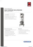
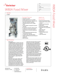
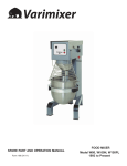
SPARE PART AND OPERATION MANUAL
FOOD MIXER
Model W20D
Caution
-READ BEFORE OPERATING-
Caution
Varimixer recommends that mixer operators be at least 18 years of age and be thoroughly trained
on the use of the mixer.
Varimixer recommends that the following precautions be adopted to help make the mixer operation
safer and more efficient.
........- All operators should be at least 18 years of age.
- All operators should be thoroughly trained before being allowed to operate the mixer.
- NEVER reach into the bowl when the mixer is running.
- Do not wear loose clothing or rings while operating the mixer.
- Stop the mixer and lower the bowl before adding ingredients, scraping the bowl, removing the
............agitator, or removing the product.
- Stop the mixer before removing or installing attachments into the drive hub.
- Do not attempt to assemble or disassemble attachments while mounted into the drive hub.
- Always use the pusher plate with the slicer/meat grinder attachments.
- NEVER bypass the safety mechanisms supplied on the mixer. Doing so can cause injury and
the responsibility of the user to insure these safety mechanisms are operating properly.
............is
Mixer Capacity Chart
Cookie, Dough
Muffins
Mashed Potatoes
Pancakes, Waffles
Whipped Cream
Cake, Layer
Eggs & Sugar
Icing , Fondant
Egg Whites
Cake, Cup
Cookies, Sugar
14 Lbs.
24 Lbs.
17 Lbs.
9 Qts.
4 Qts.
23 Lbs.
9 Lbs.
14 Lbs.
1 Qt.
25 dz.
40 dz.
LIMITED WARRANTY
Varimixer warrants its commercial mixers to the original purchaser against defects in material or manufacture for a period of one
year from the date of original purchase, subject to the following exclusions and limitations. The warranties provided by Varimixer do
not apply in the following instances:
EXCLUSIONS
1. In the event that the equipment is improperly installed. Proper installation is the responsibility of the installer, proper installation
procedures are covered in the Varimixer Spare Parts and Operations Manual.
.
2. In the event that the equipment is improperly maintained. Proper maintenance is the responsibility of the user. Proper maintenance
procedures are covered in the Varimixer Spare Parts and Operations Manual.
3. In the event that failure or malfunction of the appliance or any part thereof is caused by abnormal use or is otherwise not attributable to a defect in material or manufacture.
.
4. In the event that the appliance , by whatever cause, has been materially altered from the condition in which it left the factory.
5. In the event that the rating plate has been altered or removed.
6. On parts which would normally be worn or replaced under normal conditions.
.
7. With regard to adjustments and/or calibrations. Checking of and changes in adjustments and calibrations are the responsibility of
the installer, Proper installation is the responsibility of the installer, proper installation procedures are covered in the Varimixer Spare
Parts and Operations Manual.
.
If any oral statements have been made regarding the appliance, such statements do not constitute warranties and are not part of the
contract of sale. This Limited Warranty constitutes the complete, final and exclusive statement with regard to warranties.
..THIS LIMITED WARRANTY IS EXCLUSIVE AND IS IN LIEU OF ALL OTHER WARRANTIES WHETHER ..
..WRITTEN, ORAL OR IMPLIED, INCLUDING, BUT NOT LIMITED TO, ANY WARRANTY OF..
..MERCHANTABILITY OR FITNESS FOR PARTICULAR PURPOSE OR WARRANTY AGAINST LATENT..
..DEFECTS.
LIMITATIONS OF LIABILITY
In the event of warranty claim or otherwise, the sole obligation of Varimixer shall be the repair and/or replacement at the option of
Varimixer, of the appliance or component or part thereof Such repair or replacement shall be the expense of Varimixer except that
travel over 100 miles or two hours, overtime, and holiday charges shall be,, the expense of the purchaser. Any repair or replacement
under this warranty does not constitute an extension of the origin, warranty for any period for the appliance or for any component
part thereof. Parts to be replaced under this warranty will be repaired or replaced at the option of Varimixer with new or functionally
operative parts. The liability of Varimixer on any claim of any kind, including claims based on warranty, expressed or implied, contract, negligence, strict liability or any other theories shall be solely and exclusively the repair or replacement of the product as stated
herein, an such liability shall not include, and purchaser specifically renounces any rights to recover, special, incidental, consequential or other damages of any kind whatsoever, including, but not limited to, injuries to persons or damage to property, loss of profits
or anticipated profits, or loss of use of the product.
TO SECURE WARRANTY SERVICE
If you claim a defect covered by this Limited Warranty, first direct your claim to the local Authorized Service Agency, giving model,
serial and code numbers, voltage, a description of the problem and your sales slip. If this procedure fails to be satisfactory to you,
you may write to the Varimixer National Service Manager, 5489 Campus Dr, Shreveport, Louisiana 71129; you should include the
information listed above.
TABLE OF CONTENTS
Installation Instructions...................................................................................................2
Cleaning Instructions.....................................................................................................2
Operating Instructions....................................................................................................3
Front Panel Controls......................................................................................................4
Main Body.......................................................................................................................5
Bowl Arms.....................................................................................................................7
Pulley System.................................................................................................................9
Planetary Head.............................................................................................................11
Attachment Drive..........................................................................................................13
Computer Display Panel...............................................................................................15
Bowl Screen..................................................................................................................17
Tools and Bowls............................................................................................................19
Electrical Diagrams.......................................................................................................21
Adjusting the Bowl Height.............................................................................................22
Planetary Head Removal..............................................................................................23
1
Read this page entirely BEFORE beginning installation.
VARIMIXER INSTALLATION INSTRUCTIONS
The mixer must be mounted with the rubber feet, which neutralize both shaking and rusting. If the
unit is to be installed on top of a table, the unit must be bolted down with the two bolts supplied from
the shipping pallet.
Before the mixer is connected to power, it should be checked that the voltage and frequency on the
rating plate is correct in relation to the place of installation. The rating plate is located on the rear
right side of the mixer.
WARNING
Electrical and grounding connections must comply with applicable portions of the National Electrical
Code and/or other local electrical codes................................................................ire
CLEANING
The mixer should be cleaned daily or after use.The mixer should be cleaned with a soft cloth and
clean water. Sulphonated soaps should be used with caution as they destroy the mixer's lubricants.
Never use high pressure cleaning for the mixer.
Bowls and tools of aluminium must not be washed with strong alkaline detergents (pH not bigger
than 9.0).
The soap suppliers can recommend the correct type of soap.
The mixer should be unplugged before cleaning to prevent accidental starting while cleaning.
The inside of the beater shaft should be cleaned once a day with warm, soapy water.
DOUGH HOOK CLEANING
Special care should be given to cleaning the dough hook. We recommend that it be
cleaned and sanitized in a commercial dish machine. An alternate cleaning procedure
is to vigorously scrub the hook with a hot.water and detergent solution. Use a heavy
bristled brush. After cleaning, sanitize the hook by rinsing it with a 50 ppm solution of
sodium hypochlorite.
2
Operation of the Mixer.
Power Up and Default:
1. Turn power on Mixer. (Plug in 115AC)
- 1:00 Appears on the display.
- The slow speed LED lights. (Left LED)
2. Press the bar arrow between the slow and fast LEDs.
- 2:00 Appears on the display.
- The fast speed LED lights. (Right LED)
3. Press the bar arrows between the slow and fast LEDs.
Note: These are the factory default times for slow and fast speed.
The computer will go to factory or stored times on every power up.
Setting The Slow Speed Time:
1. With the computer's Slow speed LED on. (Left LED)
2. Enter the desired time for slow speed.(minutes and seconds)
- Press the time up keys under the display.
- 99:59 is the Maximum time that can be entered.
Setting The Fast Speed Time:
1. Press the bar arrows between the slow and fast LEDs.
2. Enter the desired time for fast speed.(minutes and seconds)
- Press the time up keys under the display.
- 99:59 is the Maximum time that can be entered.
Storing Set Times:
1. With the desired slow and fast speed times entered Press and hold the bar arrow between the LEDs until
“stor” appears on the display. The time stored will be the default time on power up.
Start and Stop:
1. With the desired time for slow and fast speed entered. Press the GREEN Start button.
a. The computer will start the mixer in slow speed counting down from the entered time.
b. The slow speed LED will flash until the slow speed counter counts down.
c. If no time is entered in the slow speed counter the computer will default to a 5 sec. slow speed count down.
d. At the end of slow speed count down the computer will automatically Start the fast speed timer; which will
count down from the entered time and will stop when the counter times out.
e. The fast speed LED will flash until the fast speed counter counts down.
f. Entering 0:00 as the fast speed time will only allow you to run in slow speed.
When the slow speed timer counts down the mixer will stop.
2. The Mixer can also be Stopped by Pressing the RED Stop button.
a. The computer will return to the time entered.
Fixed Mode Operating Procedure
Getting to Fixed mode:
1. With the mixer off (unplugged) Press and hold the four time up keys located under the display.
2. Turn the power on the mixer (plug in 115AC)
3. Release the time up keys when Set appears in the display.
- - - - - appears on the display
b. The time stored from the normal mode will be the fixed time until it is changed.
3
Operation of the Mixer.
Change Time in Fixed mode:
1. Press and hold the bar arrow key for 5 sec. and release.
2. The fixed time for the slow speed will appear in the display.
- The LED for slow speed lights. (Left LED)
3. Press the time up keys under the display to enter the desired time for slow speed.
4. Press the bar arrow key.
5. The fixed time for the fast speed will appear in the display.
- The LED for fast speed lights.(Right LED)
6. Press the time up keys under the display to enter the desired time for fast speed.
7. Press and hold the bar arrow key until stor appears in the display.
- - - - - will appear in the display
8.Press the start button to run fixed times.
Bar Arrows
Slow Speed Indicator
High Speed Indicator
Time Display
Time Keys
Start Button
Stop Button
4
Body
1
2
3
4
5
6
7
8
9
10
14
13
15
11
12
16
17
18
19
20
21
5
Body
Figure Number
1.
2.
3.
4.
5.
6.
7.
8.
9.
10.
11.
12.
13.
14.
15.
16.
17.
18.
19.
20.
21.
Description
Screw
Top Lid (Painted)
Rear Access Plate
Bushing (Lift Handle)
Upper Column
Plug Button
Bushings
Column Seal
Plug Button
Lower Column
Bolt M8X20
Leg Left
Leg Right
Plug Button
Rubber Foot
NSF Cover Plate
Suspension Hook
Column Base Plate
Retaining Spring f/Plate
Lock Nut M6
Mixer Mount Bolt
6
Part Number
STA 5233
20D-21
20N-291
STA 2515
20N-22.17
STA 6561
STA 2514 (each)
20N-207
STA 6511
20N-22.30
STA 5631
20N-25.1
20N-25.2
STA 6560
20N-218
20N-304
20N-302
20N-22.35
20N-310
STA 5831
STA 5441
Bowl Arms
1
7
6
2
3
10
5
4
8
11
9
12
13
14
15
16
19
17
18
20N-62Z
7
20N-65.1Z
20N-65.1M
Bowl Arms
Figure Number
Description
Part Number
1.
2.
3.
4.
5.
6.
7.
8.
9.
10.
11.
12.
13.
14.
15.
16.
17.
18.
19.
Ball (Black)
Bowl Lift Lever
Washer
Disc With Arrow
Retaining Disc
Crank Arm
Cotter Pin
Key
Snap Ring
Lift Nut
Jam Nut
Lift Bolt
Bowl Arm Shaft
Snap Ring 25U
Bowl Arm
Snap Ring 25U
Bowl Lift Lever Assembly
Lift Bolt Assembly
Bowl Arm Shaft Assembly
STA 3306
20N-62Z
STA 6066
20N47.10
20N-47.11
20N-63M
STA 6204
STA 2019
STA 3407
20N-65.1Z
STA 5825
20N-83.1
20N-68.1M
STA 3410
20N-23
STA 3410
20N-62Z
20N-65.1M
20N-68.1M
8
Pulley System
4
5
6
7
1
3
2
8
9
Pulley System
Figure Number
Description
Part Number
1.
2.
3.
4.
5.
6.
7.
8.
Belt
Motor Pulley
Planetary Pulley
Bolt 3/8-16X3/4
Washer
Bolt M6X16
Washer
Motor
20P-91
6J19
6J60
Local Purchase Item
STA 6009
STA 5432
STA 6008
20D-85.64
10
Planetary Head
1
2
3
4
5
6
7
8
12
13
9
14
15
10
16
20
17
11
21
18
22
19
23
24
25
26
27
28
29
30
31
32
20N-2.1Z
20N-3
20N-2
20N-2.1Z
33
34
35
20-36
20N-30
20-33
20N-101
11
Planetary Head
Figure Number
Description
Part Number
1.
2.
3.
4.
5.
6.
7.
8.
9.
10.
11.
12.
13.
14.
15.
16.
17.
18.
19.
20.
21.
22.
23.
24.
25.
26.
27.
28.
29.
30.
31.
32.
33.
34.
35.
Snap Ring
Bearing 6206
Snap Ring
Bolt M6X16
Main Bearing Head
Snap Ring
Bearing 6206
Distance Piece
Gear Wheel Rim
Bolt M8X30
Main Shaft
Snap Ring
Eccentric Disc
Bearing 6006
Snap Ring
Snap Ring
Seal
Needle Bearing Race
Groove Pin
Needle Bearing set
Disc
Upper Rim Pinion
Lower Rim Pinion
Eccentric Head
Needle Bearing
Bolt
Distance Piece
Bearing 6205
Distance Piece
Snap Ring
Key
Bayonet Shaft
Stainless Cover
Black Cover
Rubber Ring
STA 3414
20-98
STA 3518
STA 5432
20N-3
STA 3518
20-98
20-37
20N-1
STA 5626
20N-30
STA 3470
20-36
20-100
STA 3515
STA 3414
20N-108R
See item 25
STA 6460
20-96
20-235
20-31
20-32
20N-2
20N-101
STA 5641
20-34
20-97
20-34
STA 3514
STA 2008
20-33
20-272
20-272.1
20-209
12
Attachment Drive
1
2
3
4
5
6
7
8
9
11
10
12
13
14
15
1 1/2”
I.D.
2” I.D.
20N-10.6M
20N-10.5M
#17 Hub
20N-10.6M
#12 Hub
13
Attachment Drive
Figure Number
1.
2.
3.
4.
5.
6.
7.
8.
8A.
9.
10.
10A.
11.
11A.
12.
13.
14.
15.
15A.
Description
Part Number
Snap Ring
Wormwheel
Snap Ring
Bearing
Distance Piece
Bearing
Key
Shaft F/ #17 Hub
Shaft F/ #12 Hub
O-ring
Hub F/ #17 (2” I.D.)
Hub F/ #12 (1 1/2” I.D.)
Thumb Screw F/ #17
Thumb Screw F/ #12
Gasket
Lock Washer
Bolt
Cover F/ #17
Cover F/ #12
STA 3410
20N-9
STA 3512
15-105
20N-37
15-105
STA 2031
20N-50
20J-50
STA 3127
20N-8
20J-8
STA 5561
4R-125
20N-211
STA 6038
STA 5631
15-214
312C
14
Computer Display Control
2
6
1
3
4
7
5
15
Computer Display Control
Figure Number
Description
Part Number
1.
Control Panel Assembly
with start/stop buttons
and computer display.
Start Button Assembly
Stop Button Assembly
Screw
Interface Board Assembly
Front Plate Casting
Ribbon Cable
Cube Relay
20E-605M
2.
3.
4.
5.
6.
7.
8.
16
31-174.2
31-174.3
STA 5230
20E-606
20N-650.5
8073882
8070834
Bowl Screen
2
3
4
10
8
11
6
5
9
7
12
13
1
14
15
16
18
17
17
Bowl Screen
Figure Number
Description
Part Number
1.
2.
3.
4.
5.
6.
7.
8.
9.
10.
11.
12.
13.
14.
15.
16.
17.
18.
Bowl Screen Kit
Bushing
Cam
Set Screw
Screw
Microswitch
Set Screw
Cam
Spacer
Bolt
Nut
Bushing
Bracket Assembly
Nut
Bolt
Rear Screen
Front Screen
Chute
225/20N
56SN20-21.1
56SN20-23
STA 5664
STA 5251
56SN20-30
STA 5664
56SN20-22.1
56SN20-24
STA 5850
STA 5816
56SN20-21.1
56SN30-13
STA 5850
STA 5360
225/20R
225/20F
56G20-280
18
Tools and Attachments
19
1, 2 ,3
19
19
4, 5
6, 7
8
19
19
16
12, 13
24
26
25
19
27
22, 22A
21, 21A
20
19
23, 23A
Tools and Attachments
Figure Number
1.
2.
3.
4.
5.
6.
7.
8.
12.
13.
16.
19.
20.
21.
21A
22.
22A
23.
23A
24.
25.
26.
Description
Part Number
S/S Bowl 20Qt
S/S Bowl 12Qt.
S/S Bowl 25Qt.
S/S Hook 20Qt.
S/S Hook 12Qt.
Flat Beater 20Qt.
Flat Beater 12Qt.
S/S Flat Beater 20 Qt.
Wire Whip 20 Qt.
Wire Whip 12 Qt.
S/S Wing Whip 20 Qt.
Pin
Rack
Bowl Scraper 20 Qt.
Bowl Scraper 12 Qt.
Arm W / Blade 20 Qt.
Arm W / Blade 12 Qt.
Nylon Blade 20 Qt.
Nylon Blade 12 Qt.
Scraper Holder
Bolt
Washer
203/20N
203/12N
203/20C
213/20A
213/12N
205/20A
205/12N
204/20A
207/20A
207/12N
209/20A
STA 6259
222
224/20A
224/12N
42R20-102
42RN12-102
42R20-204
42RN12-204
42R20-101M
STA 5648
STA 6020
20
Wiring Diagram
Start
.3
N.O.
.4
Stop
.1
N.C.
.2
J5
J6
115V
J7
J8
2
1
Blue
White
Green
3
2
1
6
5
4
Red
Black
Orange
Bowl Screen
Microswitch
Motor Plug
21
Black
Green
White
Bowl Height Adjustment
10
9
1
7
2
3
8
4
6
5
A) Lower the bowl arms.
B) Loosen the counter nut (2) and remove the cotter pin. (1)
C) Remove the lifting bolt (6) and the lifting nut. (8)
D) Adjust the bowl height by turning the lifting nut (8) either in or out, on the
..... lifting bolt.
E) Mount the lifting bolt with the lifting nut and the cotter pin, tighten the the
..... counter nut. (2)
D) Ensure all mixing tools fit and do not hit the bowl.
22
Planetary Head Removal
4
3
2
1
5
6
7
13
8
10
11
12
9
GREASE TYPES
.....-On repair of the planetary head: Grease the toothed wheel and the toothed rim with Nye Gel
.868VH, (PN WHITE GREASE), the needle bearings in the planetary head must not be
...........lubricated with this type of grease, they should be lubricated with Lubriplate #1200-2.
.........Do not use any other type of grease than the ones stated here.
........-On repair of the attachment drive: Fill the attachment drive with Tribol Molub 860/150-0,
...................................................................(PN 860/150-0).
23
Planetary Head Removal
1. Remove the top lid (1), attachment hub (7), the drive belt (2) and the front
....control panel (4).
2
2. The plastic ring (13) can be removed with a screwdriver by pressing it
....between the plastic ring and the frame, and then prying it down.
2
.
3. Remove the rubber ring (10) and the stainless steel cover (12) by prying it
....off with a screwdriver.
2
4. If only the lower part of the planetary head is to be repaired, the planetary
....head can be separated by removing the 3 bolts (11).
3
5. Loosen the set screw and remove the front pulley (3) . A 3 armed pulley
....puller may be required.
6. Take out the 4 screws (5).
7. By loosening and removing the 4 bolts (8), the planetary can be lowered
....and removed.
3
24
5489 Campus Drive
Shreveport LA 71129
(800) 222-1138
(318) 635-3131 Fax