1
User Manual
Starlink SL9003Q
Digital Studio Transmitter Link
Doc. 602-12016-01
Revision G
Released February 2006
Moseley SL9003Q
602-12016 Revision G
ii
WARRANTY
All equipment designed and manufactured by Moseley Associates, Inc., is
warranted against defects in workmanship and material that develop under normal use
within a period of (2) years from the date of original shipment, and is also warranted to
meet any specifications represented in writing by Moseley Associates, Inc., so long as
the purchaser is not in default under his contract of purchase and subject to the following
additional conditions and limitations:
1.
The sole responsibility of Moseley Associates, Inc., for any equipment not
conforming to this Warranty shall be, at its option:
A.
to repair or replace such equipment or otherwise cause it to meet the
represented specifications either at the purchaser's installation or upon the return thereof
f.o.b. Santa Barbara, California, as directed by Moseley Associates, Inc.; or
B.
to accept the return thereof f.o.b. Santa Barbara, California, credit the
purchaser's account for the unpaid portion, if any, of the purchase price, and refund to
the purchaser, without interest, any portion of the purchase price theretofore paid; or
C.
to demonstrate that the equipment has no defect in workmanship or
material and that it meets the represented specification, in which event all expenses
reasonably incurred by Moseley Associates, Inc., in so demonstrating, including but not
limited to costs of travel to and from the purchaser's installation, and subsistence, shall
be paid by purchaser to Moseley Associates, Inc.
2.
In case of any equipment thought to be defective, the purchaser shall
promptly notify Moseley Associates, Inc., in writing, giving full particulars as to the
defects. Upon receipt of such notice, Moseley Associates, Inc. will give instructions
respecting the shipment of the equipment or such other manner as it elects to service
this Warranty as above provided.
3.
This Warranty extends only to the original purchaser and is not
assignable or transferable, does not extend to any shipment which has been subjected
to abuse, misuse, physical damage, alteration, operation under improper conditions or
improper installation, use or maintenance, and does not extend to equipment or parts
not manufactured by Moseley Associates, Inc., and such equipment and parts are
subject to only adjustments as are available from the manufacturer thereof.
4.
NO OTHER WARRANTIES, EXPRESS OR IMPLIED, SHALL BE
APPLICABLE TO ANY EQUIPMENT SOLD BY MOSELEY ASSOCIATES, INC., AND
NO REPRESENTATIVE OR OTHER PERSON IS AUTHORIZED BY MOSELEY
ASSOCIATES, INC., TO ASSUME FOR IT ANY LIABILITY OR OBLIGATION WITH
RESPECT TO THE CONDITION OR PERFORMANCE OF ANY EQUIPMENT SOLD BY
IT, EXCEPT AS PROVIDED IN THIS WARRANTY. THIS WARRANTY PROVIDES
FOR THE SOLE RIGHT AND REMEDY OF THE PURCHASER AND MOSELEY
ASSOCIATES, INC. SHALL IN NO EVENT HAVE ANY LIABILITY FOR
CONSEQUENTIAL DAMAGES OR FOR LOSS, DAMAGE OR EXPENSE DIRECTLY
OR INDIRECTLY ARISING FROM THE USE OF EQUIPMENT PURCHASED FROM
MOSELEY ASSOCIATES, INC.
Moseley SL9003Q
602-12016 Revision G
iii
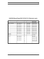
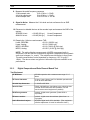
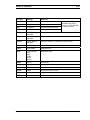
SL9003Q Manual Dwg # 602-12016-01 R: G Revision Levels:
SECTION
DWG
REV
ECO
REVISED/
RELEASED
Table of Contents
602-12016-TC1
D
DCO1065
October 2003
1
602-12016-11
D
DCO1065
October 2003
2
602-12016-21
D
DCO1065
October 2003
3
602-12016-31
D
DCO1065
October 2003
4
602-12016-41
D
DCO1065
October 2003
5
602-12016-51
D
DCO1065
October 2003
6
602-12016-61
D
DCO1065
October 2003
7
602-12016-71
D
DCO1065
October 2003
Appendix
602-12016-A1
D
DCO1065
October 2003
Figure 5.7
D
July 2004
2, 4 & 5
602-12016-01
E
May 2005
3.2.1
602-12016-01
F
November 2005
4.4.1
602-12016-01
F
November 2005
5.2
602-12016-01
F
November 2005
G
February 2006
Moseley SL9003Q
602-12016 Revision G
iv
Moseley SL9003Q
602-12016 Revision G
v
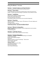
Using This Manual - Overview
Section 1 System Features and Specifications
A short discussion of the SL9003Q features and specifications.
Section 2 Quick Start
For the experienced user that wants to get the system up and running as soon as
possible. Contains typical audio settings, RF parameters, and performance checks.
Section 3 Installation
Detailed system installation information covering:
Primary power requirements (AC/DC)
Bench test details (for initial pretest)
Site installation details (environmental, rack mount and link alignment)
Section 4 Operation
Reference section for front panel controls, LED indicators, LCD screen displays and
software functions:
Front panel controls & indicators
Screen Menu Structure – menu tree & navigation techniques
Screen Summary Tables – parameters & detailed functions.
Section 5 Module Configuration
Listings of jumpers, settings and options useful for diagnosis and custom systems:
Module configuration
Troubleshooting guide
Section 6 Customer Service
Information to obtain customer assistance from the factory.
Section 7 System Information
System theory discussion for a better understanding of the SL9003Q:
System Block Diagrams
Module Details and Block Diagrams
Appendices
Additional material for reference and design. These include:
Path Evaluation Information
Audio Considerations
Glossary of Terms
Conversion Chart (microvolts to dBm)
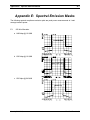
Spectral Emission Masks
Redundant Configurations
Use in Hostile Environments
Moseley SL9003Q
602-12016 Revision G
vi
Moseley SL9003Q
602-12016 Revision G
vii
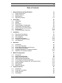
Table of Contents
1
System Features and Specifications
1.1
1.2
1.3
1.4
2
Quick Start
2.1
2.2
2.3
2.4
2.5
2.6
2.7
2.8
3
Introduction
Front Panel Operation
Screen Menu Navigation and Structure
Screen Menu Summaries
Intelligent Multiplexer PC Interface Software
NMS/CPU PC Interface Software
Module Configuration
5.1
5.2
5.3
5.4
5.5
5.6
5.7
5.8
5.9
6
Rear Panel Connections
Preliminary Bench Tests
Site Installation
Antenna/Feed System
Transmitter Antenna Testing
Link Alignment
Operation
4.1
4.2
4.3
4.4
4.5
4.6
5
Unpacking
Notices
Rack Mount
Typical System Configurations
Transmitter Power-Up Setting
Default Settings and Parameters
Performance
For More Detailed Information...
Installation
3.1
3.2
3.3
3.4
3.5
3.6
4
System Introduction
System Features
Specifications
Regulatory Notices
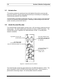
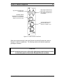
Introduction
Audio Encoder/Decoder
Digital Composite System
QAM Modulator/Demodulator
IF Card Upconverter/Downconverter
Transmit/Receiver Module (RF Up/Downconverter)
Power Amplifier
MUX Module
NMS/CPU Module
Customer Service
6.1
6.2
6.3
6.4
Introduction
Technical Consultation
Factory Service
Field Repair
Moseley SL9003Q
1-1
1-2
1-3
1-4
1-11
2-1
2-2
2-2
2-4
2-4
2-8
2-10
2-12
2-14
3-1
3-2
3-5
3-14
3-17
3-19
3-19
4-1
4-2
4-2
4-7
4-9
4-33
4-33
5-1
5-2
5-2
5-9
5-11
5-12
5-12
5-15
5-16
5-18
6-1
6-2
6-2
6-3
6-4
602-12016 Revision G
viii
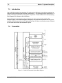
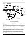
7
System Description
4.7
4.8
4.9
8
7-1
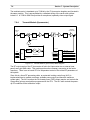
Introduction
Transmitter
Receiver
7-2
7-2
7-8
Appendices
8-1
Appendix A: Path Evaluation Information
A-1
Appendix B: Audio Considerations
B-1
Appendix C: Glossary of Terms
C-1
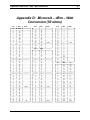
Appendix D: Microvolt – dBm – Watt Conversion (50 ohms)
D-1
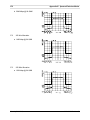
Appendix E: Spectral Emission Masks
E-1
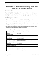
Appendix F: Redundant Backup with TP64 and TPT-2 Transfer Panels
F-1
Appendix G: Optimizing Radio Performance For Hostile Environments
G-1
Appendix H: FCC APPLICATIONS INFORMATION - FCC Form 601
H-1
Moseley SL9003Q
602-12016 Revision G
ix
List of Figures
Figure 2-1 SL9003Q Typical Rack Mount Bracket Installation......................................2-4
Figure 2-2 SL9003Q 2 or 4 Channel Digital STL Setup ................................................2-5
Figure 2-3 SL9003Q Repeater Setup ...........................................................................2-6
Figure 2-4 SL9003Q Digital Composite Setup ..............................................................2-7
Figure 2-5 Radio TX Status Performance Check ........................................................2-13
Figure 2-6 RX Modem Status Performance Check ....................................................2-14
Figure 3-1 SL9003Q AC Power Supply ........................................................................3-3
Figure 3-2 SL9003Q DC Power Supply ........................................................................3-4
Figure 3-3 SL9003Q Discrete Audio Bench Test Setup................................................3-6
Figure 3-4 SL9003Q Digital Composite Bench Test Setup ...........................................3-7
Figure 3-5 Receiver Site Installation Details ..............................................................3-15
Figure 3-6 Rack Ear Bracket Mounting Methods ........................................................3-17
Figure 3-7 Transmitter Antenna Testing .....................................................................3-18
Figure 4-1 SL9003Q Front Panel ..................................................................................4-2
Figure 4-2 Main Menu Screen.......................................................................................4-7
Figure 4-3 Radio Launch Menu Screen Navigation ......................................................4-7
Figure 4-4 Top Level Screen Menu Structure ...............................................................4-9
Figure 4-5 Factory Calibration-Radio TX Screens .....................................................4-13
Figure 4-6 Factory Calibration-Radio RX Screens ......................................................4-14
Figure 4-7 Factory Calibration-QAM Modem Screens ................................................4-14
Figure 4-8 Factory Calibration-System Screens ........................................................4-15
Figure 5-1 Audio Encoder Front Panel..........................................................................5-2
Figure 5-2 Audio Decoder Front Panel .........................................................................5-3
Figure 5-3 Audio Encoder PC Board / Switch & Jumper Settings.................................5-5
Figure 5-4 Audio Decoder PC Board / Switch & Jumper Settings.................................5-6
Figure 5-5 AES/EBU-XLR Encoder Connection............................................................5-7
Figure 5-6 SPDIF-XLR Encoder Connection.................................................................5-7
Figure 5-7 AES/EBU-XLR Decoder Connection ...........................................................5-7
Figure 5-8 SPDIF-XLR Decoder Connection ................................................................5-7
Figure 5-9 Data Channel Connector- DSUB (9-pin).....................................................5-8
Figure 5-10 Burk Remote Control Interconnection with Auxiliary Data Channel........5-10
Figure 5-11 QAM Modem Front Panel .........................................................................5-11
Figure 5-12 Up/Down Converter Front Panel..............................................................5-12
Figure 5-13 Composite MUX (4-Port) Front Panel ......................................................5-16
Figure 5-14 6-Port MUX Front Panel ..........................................................................5-17
Figure 5-15 SL9003Q NMS Card ...............................................................................5-18
Figure 5-16 NMS Card External I/O Pinout ................................................................5-19
Figure 5-17 Representative Internal Relay Wiring .....................................................5-20
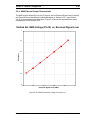
Figure 5-18 NMS External RSL Voltage Curve (Pin 10) .............................................5-25
Fiigure 7-1 SL9003Q Transmitter System Block Diagram ............................................7-2
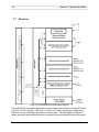
Figure 7-2 Audio Encoder Block Diagram .....................................................................7-4
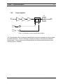
Figure 7-3 IF Upconverter Daughter Card Block Diagram ..........................................7-5
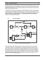
Figure 7-4 Transmit Module (Upconverter) Block Diagram.........................................7-6
Figure 7-5 SL9003Q RF Power Amplifier Block Diagram .............................................7-7
Figure 7-6 SL9003Q Receiver System Block Diagram .................................................7-8
Figure 7-7 Receiver Module Block Diagram ................................................................7-9
Figure 7-8 SL9003Q IF Downconverter Daughter Card Block Diagram .....................7-10
Figure 7-9 Audio Decoder Block Diagram...................................................................7-11
Figure 8-1 Starlink SL9003Q Transmitter Main/Standby Configuration ....................... F-4
Moseley SL9003Q
602-12016 Revision G
x
Figure 8-2 Starlink SL9003Q RX Main/Standby Connection (w/OPTIMOD)..................F-5
Figure 8-3 Receiver Audio Output Switching-External Control (Discrete or Digital Audio)
................................................................................................................................F-6
Figure 8-4 Starlink Digital Composite Transmitter Main/Standby Configuration ..........F-8
Figure 8-5 Starlink Digital Composite Receiver Main/Standby Configuration ............F-10
Figure 8-6 Starlink TX & RX NMS-Transfer I/O Connection ......................................F-12
Figure 8-7 Starlink Digital Composite with PCL Series TX Backup ............................F-13
Figure 8-8 Starlink Digital Composite RX and PCL Series RX Backup .....................F-14
Figure 8-9 Starlink QAM TX with DSP/PCL TX Backup and TPT-2 Connection .......F-17
Figure 8-10 Starlink QAM RX with DSP/PCL RX Backup and Optimod Connection .F-18
Figure 8-11 Starlink QAM RX with DSP/PCL RX Backup and Router Connection....F-20
Figure 8-12 TP64 Front Panel ...................................................................................F-21
Figure 8-13 STARLINK – TP64 Control Cable Adaptor 230-12127-01 ......................F-24
List of Tables
Table 2-1 Encoder/Decoder Typical Settings ............................................................2-10
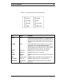
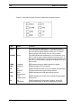
Table 4-1 LED Status Indicator Functions (Transmitter)...............................................4-4
Table 4-2 LED Status Indicator Functions (Receiver)..................................................4-5
Table 4-3 LED Status Indicator Functions (Repeater/Full Duplex Systems) ................4-6
Table 5-1 NMS External I/O Pin Descriptions ............................................................5-19
Table 8-1 Typical Antenna Gain ...................................................................................F-7
Table 8-2 Free Space Loss..........................................................................................F-7
Table 8-3 Transmission Line Loss ...............................................................................F-7
Table 8-4 Branching Losses ........................................................................................F-8
Table 8-5 Typical Received Signal Strength required for BER of 1x10E-4* .................F-8
Table 8-6 Relationship Between System Reliability & Outage Time ..........................F-12
Table 8-7 Fade Margins Required for 99.99% Reliability, Terrain Factor of 4.0, and
Climate Factor of 0.5 ............................................................................................F-12
Table 8-8 TP64 Transmitter Master/Slave Logic ........................................................F-22
Table 8-9 TP64 Receiver Master/Slave Logic ...........................................................F-22
Table 8-10 Interleave Setting vs. Delay ...................................................................... G-3
Moseley SL9003Q
602-12016 Revision G
1 System Features and
Specifications
Moseley SL9003Q
602-12016 Revision G
1-2
1.1
Section 1: System Features and Specifications
System Introduction
The Moseley STARLINK 9000 is the first all-digital, open-architecture, modular system
for CD-quality audio transmission. The versatility and power of the STARLINK 9000
comes from a complete range of “plug and play” personality modules.
The SL9003Q Digital Studio-Transmitter Link (DSTL) provides a transmitter/receiver pair
that conveys high quality digital audio, either discrete or composite audio program
information, across a microwave radio path. Typically, program material is transmitted
from a studio site to a remote transmitter site, to a repeater site, or in an intercity relay
application.
Utilizing spectrally efficient digital Quadrature Amplitude Modulation (QAM) technology,
the SL9003Q delivers either four discrete 16-bit linear audio channels with two data
channels or a 16-bit linear stereo composite channel with up to three data channels over
standard FCC Part 74 (950 MHz) STL frequency allocations.
As a discrete STL, the AES/EBU digital audio I/O, combined with a built-in variable
sample rate converter, provide seamless connection to the all-digital air chain without
compression. The system has provisions for two asynchronous auxiliary data channels
(up to 38,400 baud) that are used for communication in remote control applications.
Plug-in MPEG audio modules and a digital multiplex allow for additional program, voice,
FSK, async and sync data channels.
As a composite STL, the stereo I/O allows transparent analog-composite transmission
directly from the audio processor/stereo generator at the studio site to the FM exciter at
the transmitter site. The analog composite signal is digitized and transmitted digitally
providing both error-free RF performance and significant sonic benefit; near flawless
channel response that exceeds most generation equipment, ultimate stereo separation,
dynamic range, and virtually no low-end frequency overshoot. The digital composite
STL operates similar to a traditional analog composite STL, such as the Moseley PCL6000 and PCL-606C series, and can directly replacement an existing analog composite
STL (with special considerations for mixed analog-STL/digital-STL hot-standby
configurations – see appendix).
The high spectral efficiency of the SL9003Q is achieved by user-selectable 16, 32, 64 or
128 QAM. Powerful Reed-Solomon error correction with interleaving, coupled with 20tap adaptive equalization, provide unsurpassed error-free signal robustness in hostile RF
environments for which there is no comparable benefit in analog transmission.
Moseley SL9003Q
602-12016 Revision G
Section 1: System Features and Specifications
1.2
1-3
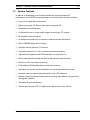
System Features
In addition to establishing a new industry standard for studio-transmitter link
performance, the SL9003Q incorporates many new and innovative features, including:
•
Linear 16 bit digital audio performance.
•
Higher system gain, 26 dB more than analog composite STL.
•
Degradation-free multiple hops.
•
Configurable for up to 4 linear audio program channels per STL system.
•
No crosstalk between channels.
•
No background chatter from co-channel or adjacent-channel interference.
•
Built-in AES/EBU digital audio interface.
•
Operation through fractional T1 networks.
•
Composite response to 0.1 Hz for improved processing loudness.
•
Highest stereo separation and SNR achievable in a composite STL.
•
Built-in data channels alleviate the need for FM subcarrier data channels.
•
Extensive LCD screen status monitoring.
•
Peak-reading LED bar graph display for all audio channels.
•
Adjustable bit error rate threshold indication for monitoring transmission quality.
•
Important status functions implemented with bi-color LED indicators.
•
Modular construction that provides excellent shielding, high reliability, easy servicing,
and upgrade capability
•
Selectable RF spectral efficiency.
•
Sample rate converter (SRC) for digital audio operation from 30 to 50 kHz.
Moseley SL9003Q
602-12016 Revision G
1-4
1.3
Section 1: System Features and Specifications
Specifications
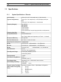
1.3.1.
System Specifications - Discrete
Audio Capacity
4 linear (32 or 44.1 kHz sample rate) + 2 data channels;
(Typical Configurations)
2 linear (44.1 kHz sample rate) + LAN (500 kbps) with 6-port
MUX
2 linear (44.1 kHz sample rate) + 1 data channel
Frequency Range(s)
160-240 MHz
330-512 MHz
800-960 MHz
1340-1520 MHz
1650-1700 MHz
(Fully Synthesized, front-panel programmable, no adjustments)
Frequency Step Size
25 kHz
Occupied Bandwidth
200/250/300/500 kHz
Note: Rate & QAM mode dependent, see Table 1-1 for details.
RF Spectral Efficiency
See Appendix
Threshold Performance
See Table 1-1 below for details.
Audio Frequency Response vs. Sample Rate:
32 kHz:
0.5 Hz-15 kHz; -3 dB bandwidth, +/- 0.2 dB flatness
44.1 kHz:
0.5 Hz-20 kHz; -3 dB bandwidth, +/- 0.2 dB flatness
48 kHz:
0.5 Hz-22.5 kHz;
Audio Distortion
<0.01%
<0.01% at 1 kHz (compressed)
Audio Dynamic Range
92 dB Digital (AES/EBU) IN/OUT
-3 dB bandwidth, +/- 0.2 dB flatness
83 dB Analog IN/OUT
Audio Crosstalk
< -80 dB
Audio Data Coding Method
Linear
ISO/MPEG (Layer II)
Audio Sample Rate
Selectable 32, 44.1, 48 kHz built-in rate converter
Audio Coding Time Delay
Linear: 0 ms
ISO/MPEG:
22 ms
Channel Coding Time Delay
Depends on Interleave Factor - QAM Modem Configuration:
(Add to Audio Coding Delay
above)
1234612 -
Moseley SL9003Q
2.6 mS
3.7 mS
5.0 mS (typical)
6.0 mS
8.0 mS
14.0 mS
602-12016 Revision G
Section 1: System Features and Specifications
1-5
Bit Error Immunity
>1X10E-4 for no subjective loss in audio quality
Async Data Channels
One for each audio pair
Aggregate Transmission
Rates
Depends on number of audio channels
Diagnostics
FWD Power, REV Power, TX Lock, Radiate, RSL, BER, RX
Lock
Status Indicators
Full Duplex: Fault, Alarm, Loopback, TX, TXD, RX, RXD,
NMS/CPU.
Transmitter: Fault, Alarm, VSWR, Radiate, Standby, AFC Lock,
Modulator Lock, NMS/CPU.
Receiver: Fault, Alarm, Attenuator, Signal, BER, AFC Lock,
Demodulator Lock, NMS/CPU.
Fault Detection and
Logging
REV Power, PA Current, LO Level, Exciter Level, RSL, BER,
Synth Level, Modem Level
Alarm Detection and
Logging
FWD Power, AFC Lock , PA Temp, MBAUD, DBAUD, DFEC
Temperature Range
Specification Performance: 0 to 50º C
Operational: -20 to 60º C
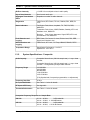
1.3.2.
System Specifications - Composite
Audio Capacity
Composite Stereo linear (128 kHz sample rate) + 1 async. data
channel;
Composite Stereo linear (145 kHz sample rate) + 1 async. data
channel + 2 configurable sync/async data channels
Frequency Range
160-240 MHz
330-512 MHz
800-960 MHz
1340-1520 MHz
1650-1700 MHz
(Fully Synthesized, front-panel programmable, no adjustments)
Frequency Step Size
25 kHz
Occupied Bandwidth
See Table 1-1 below for details.
RF Spectral Efficiency
See Appendix
Threshold Performance
See Table 1-1 below for details.
Composite Frequency Response vs. Sample Rate:
128 kHz:
0.1 Hz – 60 kHz;
-3 dB bandwidth
0.2 Hz – 53 kHz; +/- 0.02 dB flatness
145 kHz:
0.1 Hz – 68 kHz;
-3 dB bandwidth
0.2 Hz – 60 kHz; +/- 0.02 dB flatness
Moseley SL9003Q
602-12016 Revision G
1-6
Section 1: System Features and Specifications
Audio Distortion
0.035% or less, 50 Hz to 15 kHz (de-emphasized, 20 Hz – 15
kHz bandwidth, referenced to 100% modulation, unweighted).
Stereo Separation
> 65 dB, 50 Hz to 15 kHz , typically 70 dB or better (referenced
to 100% modulation = 3.5Vp-p)
> 60 dB, 50 Hz to 15 kHz for Matched Digital Composite Links in
Hot-Standby configuration
Signal-to-Noise Ratio
> 82 dB, typically better than 85 dB
(75µs De-emphasized, 100% modulation, 50 Hz to 15 kHz)
Nonlinear Crosstalk
> -80 dB, main channel to sub-channel or sub-channel to main
channel (referenced to 100% modulation).
Encoding Method
Linear, 16 bit
Composite Coding Time
Delay
0 ms
Channel Coding Time Delay
Interleave Factor - QAM Modem Configuration:
(Add to Audio Coding Delay
above)
1234612 -
Bit Error Immunity
>1x10e-4 for no subjective loss in audio quality
Async Data Channels
One 300 baud standard, up to 9600 baud, and choice of
Asynchronous: 300-38400 bps; Synchronous: 16, 24, 32, 64
kbps;
Aggregate Transmission
Rates
2048 kbps/2432 kbps depending on configuration
Diagnostics
FWD Power, REV Power, TX Lock, Radiate, RSL, BER, RX
Lock
Status Indicators
Full Duplex: Fault, Alarm, Loopback, TX, TXD, RX, RXD,
NMS/CPU.
Transmitter: Fault, Alarm, VSWR, Radiate, Standby, AFC Lock,
Modulator Lock, NMS/CPU.
Receiver: Fault, Alarm, Attenuator, Signal, BER, AFC Lock,
Demodulator Lock, NMS/CPU.
Fault Detection and
Logging
REV Power, PA Current, LO Level, Exciter Level, RSL, BER,
Synth Level, Modem Level
Alarm Detection and
Logging
FWD Power, AFC Lock , PA Temp, MBAUD, DBAUD, DFEC
Temperature Range
Specification Performance: 0 to 50º C
Operational: -20 to 60º C
Moseley SL9003Q
2.6 mS
3.7 mS
5.0 mS (typical)
6.0 mS
8.0 mS
14.0 mS
602-12016 Revision G
Section 1: System Features and Specifications
1-7
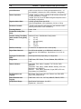
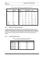
Table A- 1
Bit Rate, Threshold and Bandwidth for SL9003Q Equipment Variations
Bit Rate
10E-4 Threshold
(dBm)
Bandwidth **
(kHz)
Application
(kbps)
16
QAM
32
QAM
64
QAM
16
QAM
32
QAM
64
QAM
2-Channel Linear Audio
32 kHz Sample
& 1 data channel
1024
-93
-91
-89
300
250
200
2-Channel Linear
48 kHz Sample
& 1 Data Channel
1536
-91.5
-89.5
-87.5
450
375
300
4-Channel Linear
32 kHz Sample
& 2 Data Channels
2048
-90
-88
-86
600
500
400
2432
-
-
-85
-
-
500
Composite Stereo
Linear Channel 128 kHz
Sample
& 1 async. data channel
Composite Stereo
Linear Channel 145 kHz
Sample
& 1 async./2 sync data
chnl
** Measured using FCC 50/80 dB Digital Mask.
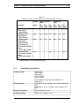
1.3.3.
Transmitter Specifications
Frequency Range
160-240 MHz
330-512 MHz
800-960 MHz
1340-1520 MHz
1650-1700 MHz
(Fully Synthesized, front-panel programmable, no
adjustments)
RF Power Output
1 Watt @ 16, 32, 64, 128 QAM, 160-240/330-512/800-960
MHz
0.5 Watt @ 16, 32, 64, 128 QAM, 1340-1520/1650-1700
MHz
RF Output Connector
Type N (female), 50 ohms
Frequency Stability
0.00001 % (0.1 PPM), 0 – 50º C
Moseley SL9003Q
602-12016 Revision G
1-8
Section 1: System Features and Specifications
Spurious and Harmonic
Emission
< -60 dBc
Type of Modulation
User Selectable: 16, 32, 64, 128 QAM
FCC Emission Type
Designation
200KD7W
250KD7W
300KD7W
500KD7W
FCC Identifier
CSU9WKSL9003Q74
Power Source
AC:
DC:
Power Consumption
70 Watts
Dimensions
17” W x 14” D x 5.2” H (3RU) [ 43.2 cm x 35.6 cm x 13.2 cm]
Weight
24 lbs. (52.8 kg)
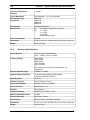
1.3.4.
Universal AC, 90-260 VAC, 47-63 Hz
+/- 12 VDC
+/- 24 VDC
+/- 48 VDC
Isolated chassis ground
Receiver Specifications
Type of Receiver
Dual conversion superheterodyne
1st IF = 70 MHz, 2nd IF = 6.4 MHz
Frequency Range
160-240 MHz
330-512 MHz
800-960 MHz
1340-1520 MHz
1650-1700 MHz
(Fully Synthesized, front-panel programmable, no
adjustments)
Receiver Dynamic Range
–35 dBm to –95 dBm
Adjacent Channel Rejection
10 dB with similar Digital SL9003Q system
or with DSP 6000/PCL 6000 link.
Image Rejection
70 dB min
Antenna Connector
Type N (female), 50 ohms
Type of Demodulation
Coherent 16, 32, 64, 128 QAM
Error Correction
Reed-Solomon, t = 8
Equalizer
20 tap adaptive
Frequency Stability
0.00001 % (0.1 PPM), 0 – 50º C
BER Threshold Mute Adjust
-95 dBm
Receiver Sensitivity
See Table 1-1 above.
Power Source
Receiver power consumption: 65 Watts
Dimensions
17” W x 14” D x 5.2” H (3RU) [ 43.2 cm x 35.6 cm x 13.2 cm]
Weight
17 lbs (37.4 kg)
Moseley SL9003Q
602-12016 Revision G
Section 1: System Features and Specifications
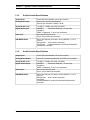
1.3.5.
1-9
Audio Encoder Specifications
Sample Rate
32/44.1/48 kHz selectable, built-in rate converter
Analog Audio Input
XLR female, electronically balanced,
600/10k ohm selectable, CMRR > 60 dB
Analog Audio Level
-10 dBu to +18 dBu, rear panel accessible
Digital Audio Input
AES/EBU:
Transformer balanced, 110 ohm input
impedance
SPDIF: Unbalanced, 75 ohm input impedance
Data Input
9-pin D male RS-232 levels
Async. 300 to 38400 bps selectable
ISO/MPEG Modes
Mono, dual channel, joint stereo, stereo (ISO/IEC 111172-3
Layer II)
Sample Rate: 32/44.1/48 kHz selectable
Output Rate:
32/48/56/64/80/96/112/128/160/192/224/256/
320/384 kHz selectable
1.3.6.
Audio Decoder Specifications
Sample Rate
32/44.1/48 kHz selectable, built-in rate converter
Analog Audio Output
XLR male, electronically balanced, low Z/600 ohm selectable
Analog Audio Level
-10 dBu to +18 dBu, rear panel accessible
Digital Audio Output
AES/EBU:
Transformer balanced, 110 ohm input
impedance
SPDIF: Unbalanced, 75 ohm input impedance
Data Output
9-pin D male RS-232 levels
Async. 300 to 38400 bps selectable
ISO/MPEG Modes
Mono, dual channel, joint stereo, stereo (ISO/IEC 111172-3
Layer II)
Sample Rate: 32/44.1/48 kHz selectable
Input Rate:
32/48/56/64/80/96/112/128/160/192/224/256/320/384 kHz
selectable
Moseley SL9003Q
602-12016 Revision G
1-10
1.3.7.
Section 1: System Features and Specifications
Composite Specifications
Input Level
3.5 Vp-p for 100% modulation; (1.8 - 4.8 Vp-p rear-panel
adjustable)
Input Type
BNC female, unbalanced, 100kohms
Output Level
3.5 Vp-p for 100% modulation; (1.8 - 4.8 Vp-p rear-panel
adjustable)
Output Type
BNC female, unbalanced, Low-Z (<5 ohms)
Output Load
75 ohms or greater, maximum load capacitance 0.047
microfarads. Maximum recommended cable length 100ft RG58A/U
Data Interface (standard)
9-pin D male, RS-232, 300 baud, 8 bit, odd parity (default)
Data Interface (optional)
2 additional channels available with choice of: Voice; Low Speed
Async Data (RS-232); High Speed Sync Data (V.35, RS-449);
15-pin D female, IBOC transport
Rates: Async data, 300-38400 bps selectable
Sync data up to 64 kbps
Voice 16, 24, 32, 64 kbps
Trunk
15-pin D female, Synchronous V.35, RS-449, EIA-530
Rates: 2048 Mbps @ 32 QAM
2432 Mbps @ 64 QAM
1.3.8.
Intelligent Multiplexer Specifications
Capacity
6 local Ports
Aggregate Rates
Up to 2.048 Mbps
Resolution
8000 bps, 768-2048 kbps; 4000 bps, 384-768 kbps; 2000 bps,
192-384 kbps, 1000 bps, 96-192 kbps; 500 bps, 48-96 kbps; 250
bps, 24-48 kbps
Clocks
Internal, Derived, External Port
Local Port Interfaces
Choice of:
UDP Stream/Ethernet
Voice; Low Speed Async Data (RS-232),
High Speed Sync Data (V.35, RS-449)
Data Rates
Low Speed 300-38400 bps;
Voice 16, 24, 32, 64 kbps;
High Speed to 2040 kbps
Trunk
V.35 or RS-449
Moseley SL9003Q
602-12016 Revision G
Section 1: System Features and Specifications
1.4
1-11
Regulatory Notices
FCC Part 15 Notice
Note: This equipment has been tested and found to comply
with the limits for a Class A digital device, pursuant to part 15
of the FCC Rules. These limits are designed to provide
reasonable protection against harmful interference when the
equipment is operated in a commercial environment. This
equipment generates, uses, and can radiate radio frequency
energy and, if not installed and used in accordance with the
instruction manual, may cause harmful interference to radio
communications. Operation of this equipment in a residential
area is likely to cause harmful interference, in which case the
user will be required to correct the interference at his own
expense.
Any external data or audio connection to this equipment must
use shielded cables.
FCC Part 74 Equipment Authorization
The SL9003Q Transmitter has been granted Equipment
Authorization under Part 74 of the FCC Rules and Regulations.
Equipment Class:
Broadcast Transmitter Base Station
Frequency Range:
944-952 MHz
Emission Bandwidth:
200 – 500 kHz
FCC Identifier:
CSU9WKSL9003Q74
Moseley SL9003Q
602-12016 Revision G
2 Quick Start
Moseley SL9003Q
602-12016 Revision G
2-2
2.1
Section 2: Quick Start
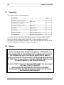
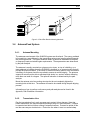
Unpacking
The following is a list of all included items.
Description
SL9003Q Transmitter (3RU)
SL9003Q Receiver (3RU)
Qty
1
(STL Link)
1
SL9003Q Transceiver (3RU)
(Repeater)
1
Rack Ears
(w/hardware)
4
Power Cord
(IEC connector)
2
Manual - CDROM
(call for printed manual)
1
Test Data Sheet
(customer documentation)
2
Be sure to retain the original boxes and packing material in case of return shipping.
Inspect all items for damage and/or loose parts. Contact the shipping company
immediately if anything appears damaged. If any of the listed parts are missing, call the
distributor or Moseley immediately to resolve the problem.
2.2
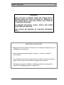
Notices
CAUTION
DO NOT OPERATE UNITS WITHOUT AN ANTENNA, ATTENUATOR, OR
LOAD CONNECTED TO THE ANTENNA PORT. DAMAGE MAY OCCUR TO
THE TRANSMITTER DUE TO EXCESSIVE REFLECTED RF ENERGY.
ALWAYS ATTENUATE THE SIGNAL INTO THE RECEIVER ANTENNA PORT
TO LESS THAN –37 dBm (3000 uV). THIS WILL PREVENT OVERLOAD AND
POSSIBLE DAMAGE TO THE RECEIVER MODULE.
DO NOT ATTEMPT TO ADJUST TRANSMITTER POWER. THIS WILL CAUSE
THE LINK TO FAIL TO OPERATE.
AVOID EXCESSIVE PRESSURE ON THE AUDIO ADJUSTMENT
POTENTIOMETERS LOCATED ON THE BACK PANELS OF THE AUDIO
ENCODER/DECODER MODULES.
Moseley SL9003Q
602-12016 Revision G
Section 2: Quick Start
2-3
WARNING
HIGH VOLTAGE IS PRESENT INSIDE THE POWER SUPPLY
MODULE WHEN THE UNIT IS PLUGGED IN. REMOVAL OF
THE POWER SUPPLY CAGE WILL EXPOSE THIS POTENTIAL
TO SERVICE PERSONNEL.
TO PREVENT ELECTRICAL SHOCK, UNPLUG THE POWER
CABLE BEFORE SERVICING.
UNIT SHOULD BE SERVICED BY QUALIFIED PERSONNEL
ONLY.
PRE-INSTALLATION NOTES
•
Always pre-test the system on the bench in its intended configuration prior to
installation at a remote site.
•
Avoid cable interconnection length in excess of 1 meter in strong RF
environments.
•
Do not allow the audio level to light the red “clip” LED on the front panel bar
graph, as this causes severe distortion (digital audio overload).
•
We highly recommend installation of lightning protectors to prevent line
surges from damaging expensive components.
Moseley SL9003Q
602-12016 Revision G
2-4
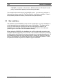
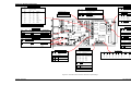
2.3
Section 2: Quick Start
Rack Mount
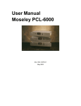
The SL9003Q is normally rack-mounted in a standard 19” cabinet. Leave space clear
above (or below) the unit for proper air ventilation of the card cage. The rack ears are
typically mounted as shown in Figure 2-1. Other mounting methods are possible, as
outlined in Section 3, Installation.
Figure 2-1 SL9003Q Typical Rack Mount Bracket Installation
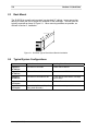
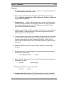
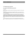
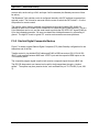
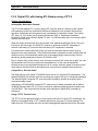
2.4
Typical System Configurations
System
Audio Channel
Auxiliary Data Channel
Digital STL
TX /RX Pair
2-Channel Linear Audio
1 data channel RS232
Digital STL
TX /RX Pair
4-Channel Linear Audio
2 data channels RS232
Digital STL
TX /RX Pair
2-Channel Linear Audio w/LAN
1 UDP Stream data channel, 544 kbps
(6-Port Mux)
Repeater
Full Duplex
No Audio Channels
No Data Channels
Repeater
Full Duplex
Up to 4 Audio Channels Drop Only
(using Audio Decoder)
1 data channel drop available
Moseley SL9003Q
602-12016 Revision G
Section 2: Quick Start
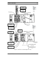
2-5
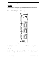
Ethernet I/O
(UDP Stream)
(RJ45-8 pin, 500 kbps typ.)
Serial Data
from Remote Control
(RS-232, 300 baud, 8 bit,
odd parity)
Optional 2nd Encoder
or 6-Port MUX
To
Antenna
950 MHz
+30 dBm
1W
SL9003Q 2 or 4 Channel
Transmitter
AC P/S
AUDIO ENC
NMS
AUDIO ENC
PWR
AMP
UP/DOWN
CONVERTER
QAM
MODEM
TRUNK
ANLG DGTL
DATA
TRUNK
N
M
S
DATA
TRUNK
110-240V, 47-63Hz
ANTENNA
TO PA
CPU
TX LOCK
TP
RESET
! CAUTION !
FOR CONTINUED PROTECTION
AGAINST RISK OF FIRE,
REPLACE WITH SAME TYPE
AND RATING OF FUSE
X
F
E
R
DISCONNECT LINE CORD
PRIOR TO MODULE REMOVAL
AES/EBU
SPDIF
12V
24V
70 MHz
IN
PA IN
LEFT
CH. 1
RIGHT
CH. 2
10V
70 MHz
OUT
MOD
LEFT
CH. 1
5V
AES/EBU
SPDIF
RIGHT
CH. 2
EXT
I /O
ID#
LIN
CMPR
TX
ID#
LIN
CMPR
RX
AES/EBU/SPDIF Digital
Audio Source
Factory default input, Zin=110
ohm, transformer balanced
LED’s are constantly
GREEN for normal
operation
Analog Audio Source
LEFT(CH.1), Right (Ch.2)
Zin = =10 kohm, active
balanced, +10dBu = O VU
From
Antenna
Optional 6 Port MUX
Ethernet I/O
(UDP Stream)
(RJ45-8 pin, 500 kbps typ.)
AC P/S
Serial Data to
Remote Control
(RS-232, 300 baud, 8
bit, odd parity)
SL9003Q 2 or 4 Channel
Receiver
AUDIO DEC
NMS
ANLG DGTL
! CAUTION !
FOR CONTINUED PROTECTION
AGAINST RISK OF FIRE,
REPLACE WITH SAME TYPE
AND RATING OF FUSE
DATA
TRUNK
110-240V, 47-63Hz
AES/EBU
SPDIF
DISCONNECT LINE CORD
PRIOR TO MODULE REMOVAL
LEFT
CH. 1
RIGHT
CH. 2
5V
10V
12V
24V
ID#
LIN
CMPR
LED constantly
GREEN for normal
operation
AES/EBU Digital Audio Out
Zin=110 ohm, transformer
balanced, 32 kHz Typical
Sample Rate
Optional 2nd Decoder
Analog Audio Source
LEFT(CH.1), Right (Ch.2)
Zout<50 ohm, active
balanced, +10dBu = O VU
LED constantly GREEN to AMBER
for normal operation (varies with
signal strength)
LED FLASHES RED when receiver
unlocked (system can take over a
minute to acquire lock from cold
start)
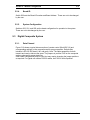
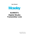
Figure 2-2 SL9003Q 2 or 4 Channel Digital STL Setup
Moseley SL9003Q
602-12016 Revision G
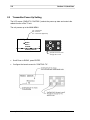
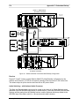
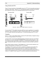
2-6
Section 2: Quick Start
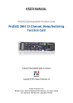
1.5 MHz Minimum
TX/RX Channel
Separation
TX
Antenna
950 MHz
+30 dBm
1W
RX
Antenna
SL9003Q Full Duplex
Repeater
Serial Data Drop (w/
Audio Decoder Option)
Ethernet Data Channel Drop
(w/ 6-port MUX Option)
AC P/S
NMS
AUDIO ENC
DEC
AUDIO
QAM
QAM
MODEM
MODEM
PWR
AMP
UP/DOWN
CONVERTER
TRUNK
ANLG DGTL
N
M
S
DATA
TRUNK
110-240V, 47-63Hz
TO PA
ANTENNA
ANTENNA
PA IN
PA IN
RX ANTENNA
CPU
TX LOCK
! CAUTION !
FOR CONTINUED PROTECTION
AGAINST RISK OF FIRE,
REPLACE WITH SAME TYPE
AND RATING OF FUSE
TP
RESET
DISCONNECT LINE CORD
PRIOR TO MODULE REMOVAL
X
F
E
R
AES/EBU
SPDIF
70
70 MHz
MHz
OUT
OUT
70 MHz
IN
MOD
MOD
LEFT
LEFT
CH. 1
RF IN
TO RX
DEMOD
RIGHT
RIGHT
CH. 2
5V
10V
12V
24V
70 MHz
IN
EXT
I /O
ID#
2 or 4 Channel Audio
Drop (w/Audio Decoder
Card Option)
LIN
CMPR
TX
RX
Demod LED constantly GREEN or
AMBER for normal operation (varies
with signal strength)
Note: FLASHES RED when receiver
unlocked (system can take over a
minute to acquire lock from cold start)
LED’s are constantly GREEN
for normal operation
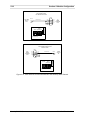
Figure 2-3 SL9003Q Repeater Setup
Moseley SL9003Q
602-12016 Revision G
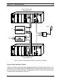
Section 2: Quick Start
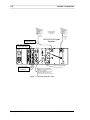
2-7
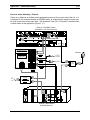
Composite from
FM Stereo
Generator/
Processor
Digital Composite
Transmitter
(BNC, 3.5 Vpp)
Serial Data from
Remote Control
LED is constantly
Amber for normal
operation
To Antenna
950 MHz
+30 dBm (1 Watt)
LED’s are constantly
GREEN for normal
operation
(RS-232, 300 baud,
8 bit, odd parity)
LED’s are constantly GREEN
for normal operation
Serial Data to
Remote Control
(RS-232, 300 baud,
8 bit, odd parity)
Composite to
FM Exciter
or Monitor
Digital Composite
Receiver
From
Antenna
Demod LED constantly GREEN or
AMBER for normal operation (varies
with signal strength)
Note: FLASHES RED when receiver
unlocked (system can take over a
minute to acquire lock from cold start)
(BNC, 3.5 Vpp)
Figure 2-4 SL9003Q Digital Composite Setup
Moseley SL9003Q
602-12016 Revision G
2-8
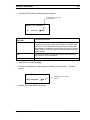
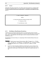
2.5
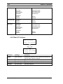
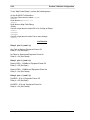
Section 2: Quick Start
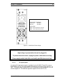
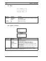
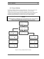
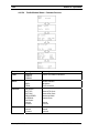
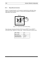
Transmitter Power-Up Setting
The LCD screen (“RADIO TX CONTROL”) selects the power-up state and controls the
radiate function of the TX unit.
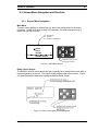
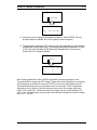
The unit powers up to the MAIN MENU:
TX = Transmitter
RX = Receiver
XC = Transceiver (Repeater)
SL9003Q TX
Main Menu
METER
RADIO
SYSTEM
v
ALARMS/FAULTS
Up/Down Arrow to scroll
through the screens
•
Scroll Down to RADIO, press ENTER.
•
Configure the launch screen for "CONTROL TX".
Moseley SL9003Q
602-12016 Revision G
Section 2: Quick Start
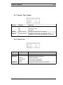
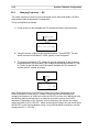
•
2-9
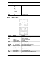
Verify the AUTO setting (default setting, as shipped).
Scroll Right/Left to choose:
AUTO/OFF/ON
Radio TX Control
TX
Radiate
RADIO TX CONTROL
SETTING
AUTO
AUTO
Functional Description
Transmitter will remain in radiate at full power unless the VSWR of
the load causes a high reverse power indication at the RFA. If this
is the case , the red VSWR LED will light and the transmitter will
cease radiating. Additionally, the transmitter will protect its RFA by
“folding back” the ALC (Automatic Level Control) under a bad load
VSWR condition.
ON
Transmitter will remain in radiate at full power under all antenna
port conditions (not recommended).
OFF
Transmitter in standby mode.
•
Press ESC to accept the setting
•
If change was made from original power-up setting, you will see the
screen:
following
Changes Made
SAVE SETTINGS?
•
NO
Scroll Right/Left to choose:
NO/YES
Choose YES, press ENTER to accept.
Moseley SL9003Q
602-12016 Revision G
2-10
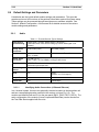
2.6
Section 2: Quick Start
Default Settings and Parameters
Listed below are the typical default module settings and parameters. This gives the
experienced user a brief rundown of the pertinent information required for system setup.
These settings may be accessed through board jumpers or software switches. See
Section 5, Module Configuration, of this manual for a detailed account of the various
module settings and parameters.
2.6.1.
Audio
Table 2-1 Encoder/Decoder Typical Settings
Audio Source
Input Switching
Digital Audio = Primary, Analog Audio = Secondary
(Automatic switch from AES to Analog Input when AES signal is not
present)
Analog Audio
Connectors
XLR female (input)
XLR male (output)
Impedance
Active balanced,
Zin = 10 kohm
Active balanced, Zout < 50 ohms
Analog Audio
Line Levels
+10 dBu = 0 VU
Note: 0 dBu = 0.7746 VRMS (1 mW @ Z=600 ohms)
Digital Audio I/O
AES/EBU: Transformer balanced, 110 ohm impedance
30-50 kHz input sample rate
Data Coding
Method
Linear (16 bit)
ISO/MPEG (Layer II)
Mode
n/a
Stereo
(ISO/IEC 111172-3 Layer II)
Sample Rate
n/a
44.1 kHz
Output Rate
n/a
256/384 kbps
2.6.1.1.
Identifying Audio Connections (4-Channel Discrete)
In a 4 channel system, there are two physically identical encoders in the transmitter unit
and two corresponding decoder modules in the receiver unit (see Fig. 2-2). The
modules are identified with an ID # on the rear panel (ENC1, ENC2, DEC1, DEC2). The
audio configuration of the module (Linear/Compressed/Data Rate) can be checked on
the Test Data Sheet supplied with the units.
Moseley SL9003Q
602-12016 Revision G
Section 2: Quick Start
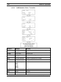
2.6.2.
2-11
Composite
The composite channel is located on the Composite MUX (4-Port) module (see Fig. 2-4).
Table 2-2 Composite MUX (4-Port) Typical Settings
2.6.3.
Input Level
3.5 Vp-p for 100% modulation
Input Type
BNC female, unbalanced, 100kohms
Output Level
3.5 Vp-p for 100% modulation
Output Type
BNC female, unbalanced, Low-Z (<5 ohms)
Output Load
75 ohms or greater, maximum load capacitance 0.047
μF. Maximum recommended cable length 100ft RG58A/U
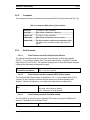
Data Channels
2.6.3.1.
Data Channels on the Encoder/Decoder Module
The normal serial data channels are located at the Encoder and Decoder (labeled
"DATA"). For 4 channel systems, ENC1 contains Data Channel 1 and ENC2 contains
Data Channel 2 (see Fig.2-2). Dip-switches located at the on Encoder/Decoder modules
configure the data channel rates and bit length.
Data Channel Encoder/Decoder Module
2.6.3.2.
9-pin D male, RS-232 levels, Asynchronous 1200 baud, 8
bits, 1 start & 1-2 stop bits.
Data Channels on the Composite MUX (4-Port) module
The Composite MUX data channel is identified by "Ch. 1" on the module (see Fig.2-4).
Jumpers on the Composite modules configure proper null-modem operation (see
Section 5, Module Configuration, for changing the data channel configuration).
Data Channel - Composite
Mux
9-pin D male, RS-232, Set for:
300 baud, 8 bit, odd parity (default)
-OR- 1200 baud, no parity (optional)
2.6.3.3.
Data Channels on the 6-Port MUX module
The 6-Port MUX is normally used in a Starlink STL system to provide an Ethernet IP
data link. The default port is labeled "Port 2".
Data Channel: 6-Port Mux
Moseley SL9003Q
Ethernet IP (UDP Stream), RJ45-8pin, 544 kbps typ.
602-12016 Revision G
2-12
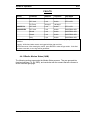
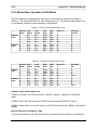
2.6.4.
Section 2: Quick Start
RF Module Parameters
The RF module parameters are optimized for the shipping configuration of the unit and
there are no user adjustments available. The following parameters are given for
reference only. The test data sheet and LCD screens will list the unit’s RF telemetry
values and will be specific to your unit.
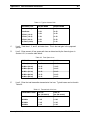
2.6.5.
Frequency (MHz)
Power Output
Average (Watts)
PA Current
(Amps)
160-240
1.0
1.5
300-512
1.0
1.5
800-960
1.0
1.5
1340 - 1520
0.5
1.5
1650-1700
0.5
1.5
QAM Modulator/Demodulator
The QAM Modulator/Demodulator module parameters are optimized for the shipping
configuration of the unit and there are no user adjustments available. The following
parameters are given for reference only. The test data sheet and LCD screens will list
the unit’s configuration and telemetry values and will be specific to your unit.
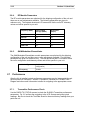
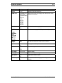
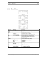
2.7
Modulation Type
16, 32, 64, 128 QAM (depends on channel
configuration)
IF Frequency
70 MHz
Performance
After the link is installed, certain performance parameters may be interrogated through
the front panel for verification. Section 4, Operations, contains an LCD Menu Flow
Diagram and other useful information to assist in navigating to the appropriate screen.
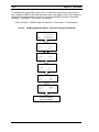
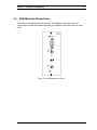
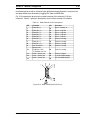
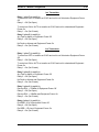
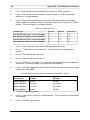
2.7.1.
Transmitter Performance Check
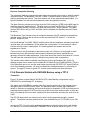
Use the RADIO TX STATUS screens to check the SL9003Q Transmitter performance
parameters. Fig. 2-5 outlines the navigation to the LCD Screens and gives typical
readings. Be sure to check the Test Data Sheet for the actual factory readings from your
particular unit.
Moseley SL9003Q
602-12016 Revision G
Section 2: Quick Start
2-13
Figure 2-5 Radio TX Status Performance Check
Moseley SL9003Q
602-12016 Revision G
2-14
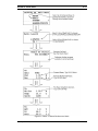
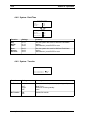
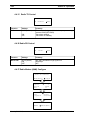
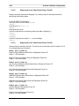
Section 2: Quick Start
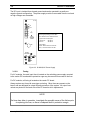
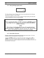
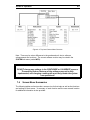
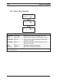
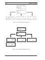
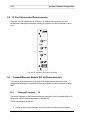
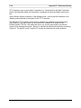
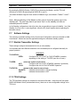
Receiver Performance Check
Use the RADIO MODEM STATUS screens to check the SL9003Q Receiver
performance parameters. Fig. 2-6 outlines the navigation to the LCD Screens and gives
typical readings. Be sure to check the Test Data Sheet for the actual factory readings
from your particular unit.
SL9003Q RX
Main Menu
METER
RADIO
v
SYSTEM
ALARMS/FAULTS
Radio Launch
STATUS
MODEM
Up/Down Arrow to make selection
and scroll through the screen
Scroll Right/Left to choose:
STATUS/CONTROL/CONFIGURE/COPY
Scroll Right/Left to choose:
TX/RX/MODEM
Received Signal Level (RSL),
Typ. -50 to -90 dBm
QAM Modem -53.3 dBm
BER Post 0.00E-00
#Bits
0.0000E+00
#Errors 0.0000E+00 v
Bit Error Rate (post-FEC),
Typ. 0.00E-00
Note: Multiple Modem Status
Screens are present, see
Section 4 (Operation) for more
details.
Figure 2-6 RX Modem Status Performance Check
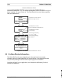
2.8
For More Detailed Information...
This “Quick Start” section was designed to give the experienced user enough
information to get the studio-transmitter link up and running. Less experienced users
may benefit by reading the manual all the way through prior to installation.
If problems still exist for your application, do not hesitate to call Moseley Technical
Services for assistance.
Moseley SL9003Q
602-12016 Revision G
3 Installation
Moseley SL9003Q
602-12016 Revision G
3-2
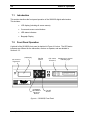
3.1
Section 3: Installation
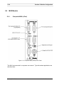
Rear Panel Connections
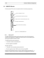
3.1.1.
Power Supply Slot
The leftmost slot in the SL9003Q card cage (as viewed from the rear of the unit) is
designated as the “PRIMARY A” power supply. This slot always contains a power
supply.
The next slot to the right is designated as “SECONDARY B”. This slot will be occupied
only if a high-power amplifier option is installed, or a redundant power supply option is
installed. The SL9003Q TX utilizes these slots to separate the PA supply lines for the
HPA option.
NOTE:
The front panel LCD screen displays the system supply voltages and the
nomenclature follows the physical location of the power supply modules.
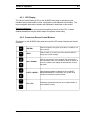
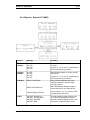
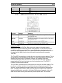
3.1.2.
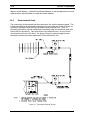
AC Power Supply
The SL9003Q TX and RX both use a high reliability, universal input switching power
supply capable. The power supply module is removable from the unit and a cage
protects service personnel from high voltage. The power supply is fan cooled to increase
reliability. The module supplies +12 V, +5 V, and +10 V for the PA (TX).
Moseley SL9003Q
602-12016 Revision G
Section 3: Installation
3-3
AC P/S
ANLG DGTL
110-240V, 47-63Hz
Universal Input: 90-260 VAC, 47-63 Hz.
! CAUTION !
FOR CONTINUED PROTECTION
AGAINST RISK OF FIRE,
REPLACE WITH SAME TYPE
AND RATING OF FUSE
DISCONNECT LINE CORD
PRIOR TO MODULE REMOVAL
5V
10V
12V
Typical Power Consumption:
Transmitter:
80 Watts
Receiver:
45 Watts
Status LED’s:
ANLG – Green Indicates +12V OK
DGTL - Green Indicates +5V OK
24V
Figure 3-1 SL9003Q AC Power Supply
CAUTION
High voltage is present when the unit is plugged in.
To prevent electrical shock, unplug the power cable before servicing.
Power supply module should be serviced by qualified personnel only.
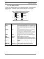
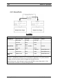
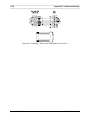
3.1.2.1.
DC Input Option
An optional DC input power supply is available for the SL9003Q TX and RX, using a
high reliability, DC-DC converter capable of operation from an input range from 20 - 72
VDC. The power supply contains two DC-DC converters; the first regulates to 12V; the
second supplies 5V. An additional regulator supplies 10V for the PA (TX).
Moseley SL9003Q
602-12016 Revision G
3-4
Section 3: Installation
The DC input is isolated from chassis ground and can be operated in a positive or
negative ground configuration. The power supply module is removable from the unit and
no high voltages are accessible.
DC P/S
ANA
DIG
RFA
PS IN
+
Nominal DC Inputs: 24 or 48 VDC
Operating Input Range: 20-72 VDC
Input Isolated from Chassis Ground
GND
INPUT
VOLTAGE
24V/48V
Typical Power Consumption:
Transmitter:
80 Watts
Receiver:
45 Watts
Status LED’s:
ANLG – Green Indicates +12V OK
DGTL - Green Indicates +5V OK
GND
OUTPUT
VOLTAGES
DIG
+5V
RFA
+10V
ANA
+12V
+12V
+24V
Figure 3-2 SL9003Q DC Power Supply
3.1.2.2.
Fusing
For AC modules, the main input fuse is located on the switching power supply mounted
to the carrier PC board and the protective cage may be removed for access to the fuse.
For DC modules, all fusing is located on the carrier PC board.
Always replace any fuse with same type and rating. Other fuses are present on the
board, and are designed for output fail-safe protection of the system. All output fuse
values are printed on the back side of the PC board to aid in replacement.
NOTE:
If a fuse does blow in operation, investigate the possible cause of the failure prior
to replacing the fuse, as there is adequate built-in protection margin.
Moseley SL9003Q
602-12016 Revision G
Section 3: Installation
3.2
3-5
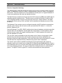
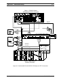
Preliminary Bench Tests
It is best to perform back-to-back tests of the entire system while the user has both
Transmitter and Receiver at the same location, prior to installation at the site. Digital
STL's have different parameters for system checks than analog STL's.
Back-to-back bench testing is a good way to familiarize the user with the SL9003Q
Discrete Audio and Composite systems. Also, the user will gain greater confidence in
the configuration and likely save a few trips to the transmitter if the actual
interconnecting equipment (such as the remote control equipment or stereo generator
for the composite system) can be tested at this time as well.
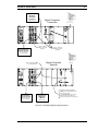
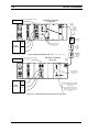
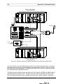
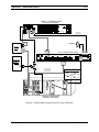
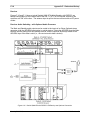
Figures 3-3 and 3-4 show a typical setup for bench testing a complete Discrete Audio
and Composite system respectively.
Caution
■ Always operate the transmitter terminated into a proper 50 ohm load.
■ Always attenuate the signal into the receiver to less than 3000 microvolts.
(Failure to observe the above precautions can cause the transmitter final
amplifier to be destroyed or the receiver preamplifier to be damaged)
■ Avoid excessive pressure on the audio adjustment potentiometers
located on the back panels of the audio encoder/decoder modules.
Moseley SL9003Q
602-12016 Revision G
3-6
Section 3: Installation
SL9003Q 2 Channel
Transmitter
RS-232, 300-9600 bps (selectable)
Serial Data I/O
AC P/S
NMS
AUDIO ENC
QAM
MODEM
950 MHz
+30 dBm
(1 W)
PWR
AMP
UP/DOWN
CONVERTER
TRUNK
ANLG DGTL
N
M
S
DATA
TRUNK
110-240V, 47-63Hz
DoubleShielded
RG142 or
Equivalent
ANTENNA
TO PA
CPU
TX LOCK
TP
RESET
! CAUTION !
FOR CONTINUED PROTECTION
AGAINST RISK OF FIRE,
REPLACE WITH SAME TYPE
AND RATING OF FUSE
X
F
E
R
DISCONNECT LINE CORD
PRIOR TO MODULE REMOVAL
AES/EBU
SPDIF
70 MHz
OUT
70 MHz
IN
MOD
PA IN
LEFT
CH. 1
RIGHT
CH. 2
5V
10V
12V
EXT
I /O
24V
TX
ID#
LIN
CMPR
RX
RF Wattmeter
(1-5W Range)
AES/
EBU
LED’s are constantly
GREEN for normal
operation
Audio
Generator
30 dB
RF Load/
Attenuator
2W
Analog
---------------------------------
Physical Separation between units > 15 ft
RS-232, 300-9600 bps (selectable)
Serial Data I/O
AC P/S
------------------------
SL9003Q 2 Channel
Receiver
RF Variable
Attenuator
(90-110 dB
combined
attenuation)
950 MHz
-57 to -77
dBm
NMS
ANLG DGTL
110-240V, 47-63Hz
! CAUTION !
FOR CONTINUED PROTECTION
AGAINST RISK OF FIRE,
REPLACE WITH SAME TYPE
AND RATING OF FUSE
DISCONNECT LINE CORD
PRIOR TO MODULE REMOVAL
LED constantly
GREEN for normal
operation
5V
10V
12V
24V
AES/
EBU
Audio
Analyzer
Analog
LED constantly GREEN to AMBER
for normal operation (varies with
signal strength)
LED FLASHES RED when receiver
unlocked (system can take over a
minute to acquire lock from cold
start)
Figure 3-3 SL9003Q Discrete Audio Bench Test Setup
Moseley SL9003Q
602-12016 Revision G
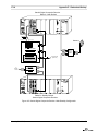
Section 3: Installation
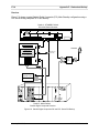
3-7
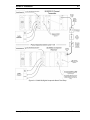
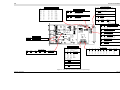
Figure 3-4 SL9003Q Digital Composite Bench Test Setup
Moseley SL9003Q
602-12016 Revision G
3-8
Section 3: Installation
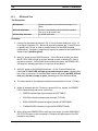
3.2.1.
RF Bench Test
Test Equipment
RF Wattmeter
950 MHz operation with a measurement range of 1–5
Watts
RF Power Attenuator
50 ohm, 5 watt “dummy load” for 950 MHz operation
with 20 to 30 dB of attenuation
Variable Step Attenuator
0–100 dB at 950 MHz
Procedure
1. Connect the equipment as shown in Fig. 3-3 for a Discrete Audio link or Fig. 3-4
for a Digital Composite STL. Be sure to physically separate the TX and RX units
by greater than 15 feet, in order to provide isolation for the BER threshold
measurement. Calculate or measure the signal level present at the SL9003Q RX
antenna input (-60 dBm typical).
2. Apply AC power to the SL9003Q receiver. On the Receiver module rear panel,
the RX LOCK LED will light up red and change to green, indicating PLL lock of
the down-converter. On the QAM Demod module rear panel, the DEMOD LED
will flash red, indicating that there is no lock yet at the demod.
3. Apply AC power to the SL9003Q transmitter. On the Transmit Module rear
panel, the TX LOCK LED will light up red and change to green, indicating PLL
lock of the up-converter. On the QAM Mod module rear panel, the MOD LED will
flash red, and then change to green, indicating lock of the QAM modulator.
4. The output power on the wattmeter should measure between 0.9 and 1.1 Watts.
5. Within 90 seconds after the TX carrier is present (30 sec. typical), the DEMOD
LED will stop blinking and turn to a solid color:
•
GREEN indicates high signal strength (ACCEPTABLE)
•
YELLOW indicates average signal strength (TYPICAL)
•
DARK ORANGE indicates low signal strength (ACCEPTABLE)
•
FLASHING RED indicates no signal (NON-OPERATIONAL)
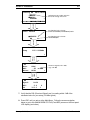
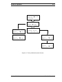
6. After verifying the DEMOD LED is within the color range, go to the QAM RADIO
RX STATUS screen on the front panel LCD display and page down to the RSL
parameter (see below).
Moseley SL9003Q
602-12016 Revision G
Section 3: Installation
3-9
SL9003Q RX
Main Menu
METER
RADIO
v
SYSTEM
ALARMS/FAULTS
Up/Down Arrow to make selection
and scroll through the screen
ENTER
Scroll Right/Left to choose:
STATUS/CONTROL/CONFIGURE/COPY
Radio Launch
Scroll Right/Left to choose:
TX/RX/MODEM
STATUS
RX
ENTER
Radio Rx Status
Freq
950.0000MHz
v
Down
Arrow
v
FORC
-60
AUTO
Rx
Synth
AFC
LO
LOCK
2.4
100.0
Received Signal Level in dBm
Typ. -60 dBm
dBm
v
Down
Arrow
Rx
Rcvr
RSL
Atten
v
V
%
7. Verify that the RSL (Received Signal Level) is reading within 2 dB of the
calculated value for your setup (-60 dBm typical).
8. Press ESC until you arrive at the Main Menu. Follow the screen navigation
below to get to the QAM MODEM STATUS (Post-BER) screen on the front panel
LCD display (see below).
Moseley SL9003Q
602-12016 Revision G
3-10
Section 3: Installation
9. With the POST-BER in the display, press ENTER. This will reset the bit counter
(# BITS) to zero. There should be no errors (# ERRORS = zero) under this
signal condition.
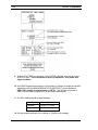
10. Verify BER threshold performance of the system as follows: Increase the variable
attenuation until the QAM MODEM STATUS (BER POST) screen displays a
BER POST reading of approximately 1.00E-06. This will take some time in
order to accumulate enough bits for an accurate measurement.
11. The RSL reading should be approximately:
2 channel:
–89 dBm (+/- 2 dBm)
4 channel:
–89 dBm (+/- 2 dBm)
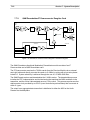
Composite:
–89 dBm (+/- 2 dBm)
12. Set the variable attenuator for a reading of -60 dBm on the display.
Moseley SL9003Q
602-12016 Revision G
Section 3: Installation
3-11
13. Reset the bit counter (press ENTER) and verify error-free operation
14. Proceed to the Audio Bench Test for further performance verification.
3.2.2.
Discrete Audio and Data Channel Bench Test
Test Equipment
RF Wattmeter
950 MHz operation with a measurement range of 1–5 Watts
RF Power Attenuator
50 ohm, 5 watt “dummy load” for 950 MHz operation with 20
to 30 dB of attenuation
Variable Step Attenuator
0–100 dB at 950 MHz
Serial I/O Data
RS232, 300-9600 bps; (equivalent to the subcarrier data port
that will be used in the site installation - use the actual
remote control equipment if possible)
Audio Distortion Analyzer
AES/EBU digital audio I/O is desirable. (Test equipment will
allow adjustment of levels for calibration check.)
Procedure
1. Connect the equipment as shown in Fig. 3-3. Be sure to physically separate the
TX and RX units by greater than 15 feet.
2. Ensure the link is RF operational as outlined in the RF Bench Test (Section
3.2.1). Adjust the attenuator for an RSL reading of –60 dBm +/- 2 dBm and
verify error-free operation.
3. Ensure that the appropriate module ID# is selected in both the Transmitter and
Receiver Units’ (in the METER LCD screen).
4. AES/EBU Digital Audio Test: Apply a 1kHz stereo tone, at a level of 0 dB (full
scale), to the Source Encoder module.
5. The front panel bar graph of the transmitter and the receiver should register a 0
dB reading for both channels.
6. Analog In/Out Audio Test: Be sure there is no AES signal at the module in
order to force the auto-switching circuitry to the analog inputs. Next, apply a 1
kHz tone, at a level of +10dBm, to the left (CH.1) channel.
7. The front panel bar graph of the transmitter and the receiver should register a 0
dB reading for Channel 1.
Moseley SL9003Q
602-12016 Revision G
3-12
Section 3: Installation
8. Measure the audio frequency response:
32 kHz sample rate:
5 Hz-15 kHz +/- 0.2 dB
44.1 kHz sample rate:
5 Hz-20 kHz +/- 0.2 dB
48 kHz sample rate:
5 Hz-22.5 kHz +/- 0.2 dB
9. Signal to Noise: Measure the 1 kHz level and set a reference for an SNR
measurement.
10. Disconnect or disable the tone at the encoder input and measure the SNR of the
system:
AES/EBU in/out:
< -90 dB (-92 typ.)
Linear/Compressed
ANALOG in/out:
< -82 dB (-84 typ.)
Linear/Compressed
11. Reapply the 1 kHz tone and measure THD:
Linear, AES/EBU:
<0.01% (.0025% typ.)
Linear, Analog:
<0.01% (.008% typ.)
MPEG, AES/EBU:
<0.01% (.003% @ 1kHz typ.)
MPEG, Analog:
<0.015% (.012% @ 1kHz typ.)
NOTE: The static distortion measurement of MPEG compressed audio is
erroneous in the fact that the compression algorithm is dependent upon dynamic
audio level changes (i.e., music). The subjective aural distortion is much lower.
The static measurement is also dependent on frequency (.007 % typ @ 712kHz). The above values are typical at 1kHz and will provide excellent on-air
performance.
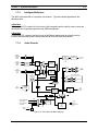
3.2.3.
Digital Composite and Data Channel Bench Test
Test Equipment
RF Wattmeter
950 MHz operation with a measurement range of 1–5
Watts
RF Power Attenuator
50 ohm, 5 watt “dummy load” for 950 MHz operation with
20 to 30 dB of attenuation
Variable Step Attenuator
0–100 dB at 950 MHz
Serial I/O Data
RS232, 300-9600 bps; (equivalent to the subcarrier data
port that will be used in the site installation, use the
actual remote control equipment if possible)
FM STereo generator
optional - digital stereo generator (Orban 8202 or
equivalent)
FM stereo monitor
optional - digital stereo demodulator (belar fmsa-1 or
equivalent)
Audio Distortion Analyzer
AES/EBU digital audio I/O is desirable. (Test equipment
will allow adjustment of levels for calibration check.)
Moseley SL9003Q
602-12016 Revision G
Section 3: Installation
3-13
Procedure
1. Connect the equipment as shown in Fig. 3-4. Be sure to physically separate the
TX and RX units by greater than 15 feet.
2. Ensure the link is RF operational as outlined in the RF Bench Test (Section
3.2.1). Adjust the attenuator for an RSL reading of –60 dBm +/- 2 dBm and
verify error-free operation.
3. Composite Test:
Apply a 400 Hz stereo tone, at a level of 0 dB (full scale),
to the left and right channels of the FM Stereo Generator for 100% modulation.
(Some digital stereo generators use –2.75 dB to represent 100% full scale,
consult your manufacturer’s information.)
4. Apply the composite signal, 100% modulation at 3.5 Vp-p to the composite input
of the transmitter. (Alternatively apply 3.5Vp-p 400 Hz tone directly from the
audio generator to check levels only).
5. The front panel bar graph of both the transmitter and the receiver should register
a -3 dB reading (YELLOW LED) for both Channel 1 and Channel 2. A slight
increase in level should indicate 0 dB reading (RED LED). ( Note: There is
exactly 2 dB of headroom above the 0 dB indication (RED LED) before the A/D
input clips).
6. Separation: Measure the 400 Hz level and set a reference for left and right
channels.
7. Disconnect the tone on the right channel to the stereo generator and measure
the level in the right channel.
Left-to-Right Separation:
> 65 dB
8. Signal to Noise: Disconnect the tone on the left channel to the stereo generator
and measure the SNR.
L/R SNR:
> 82 dB (85 typ).
9. Reapply the 400 Hz tone and measure THD.
L/R THD:
<0.035%
10. Composite Data Test: Apply the RS-232 data source to the 9-pin CHANNEL 1
connector on the Starlink transmitter and the RS-232 data receiving unit to the
Moseley SL9003Q
602-12016 Revision G
3-14
Section 3: Installation
CHANNEL 1 connector on the receiver. Default interface is 300 baud, 8 bit, odd
parity. Confirm data is properly received through the radio.
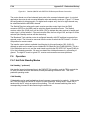
This completes the bench tests for the SL9003Q system. If you have any problems or
discrepancies, please consult the Test Data Sheet to check factory readings. If there is
still a problem, please call Moseley Technical Services (see Section 6).
3.3
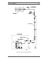
Site Installation
The installation of the SL9003Q involves several considerations. A proper installation is
usually preceded by a pre-installation site survey of the facilities. The purpose of this
survey is to familiarize the customer with the basic requirements needed for the
installation to go smoothly. The following are some considerations to be addressed
(refer to Figure 3-5 for Receiver Site Installation Details).
Before taking the SL9003Q to the installation site verify that the audio connections are
compatible with the equipment to be connected. Also, locate the information provided by
the path analysis which should have been performed prior to ordering the equipment. At
the installation site, particular care should be taken in locating the SL9003Q in an area
where it is protected from the weather and as close to the antenna as possible. Locate
the power source and verify that it is suitable for proper installation.
Moseley SL9003Q
602-12016 Revision G
Section 3: Installation
3-15
Figure 3-5 Receiver Site Installation Details
Moseley SL9003Q
602-12016 Revision G
3-16
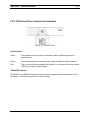
3.3.1.
Section 3: Installation
Facility Requirements
The site selected to house the SL9003Q should follow conventional microwave practice
and should be located as close to the antenna as possible. This will reduce the RF
transmission line losses, minimize possible bending and kinking of the line, and allow for
the full range potential of the radio link.
The building or room chosen for installation should be free from excessive dust and
moisture. The area should not exceed the recommended temperature range, allow for
ample air flow, and provide room for service access to cables and wiring.
3.3.2.
Power Requirements
The AC power supply uses a universal input switching supply that is adaptable to power
sources found worldwide. The line cord is IEC (USA) compatible, and the user may
need to adapt to the proper physical AC connector in use.
For DC input units, double-check the input voltage marking on the rear panel does
indeed match the voltage range provided by the facility. Verify that the power system
used at the installation site provides a proper earth ground. The DC option for the
SL9003Q have isolated inputs by default, but the user may hard-wire a negative chassis
ground inside the module, if desired.
An uninterruptible power supply backup (UPS) system is recommended for remote
locations that may have unreliable source power. Lightning protection devices are highly
recommended for the power sources and antenna feeds.
3.3.3.
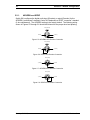
Rack Mount Installation
The SL9003Q is designed for mounting in standard 19” rack cabinets, using the rack ear
brackets included with the SL9003Q. The rack ear kit is designed to allow flush mount
or telecom-mount (front extended). See Figure 3-6 for bracket installation. Be sure to
provide adequate air space near the ventilation holes of the chassis (top, bottom, and
sides).
Moseley SL9003Q
602-12016 Revision G
Section 3: Installation
3-17
(Typical)
Figure 3-6 Rack Ear Bracket Mounting Methods
3.4
Antenna/Feed System
3.4.1.
Antenna Mounting
The antennas used as part of the SL9003Q system are directional. The energy radiated
is focused into a narrow beam by the transmitting antenna and must be aligned towards
the receiving antenna. The type of antenna used in a particular installation will depend
on frequency band and antenna gain requirements. These parameters are determined
by the path analysis.
The antenna is usually mounted on a pipe mount or tower, on top of a building, on a
tower adjacent to building where the SL9003Q is installed, or on some structure that will
provide the proper elevation. If the tower or antenna mounting mast is to be mounted on
a building, an engineer should be consulted to ensure structural integrity. The antenna
support structure must be able to withstand high winds, ice, and rain without deflecting
more than one tenth of a degree. The optimum elevation is determined by the path
analysis.
Mount the antenna onto its mounting structure but do not completely tighten the
mounting bolts at this time. The antenna will need to be rotated during the path aligning
process.
Information on how to perform a site survey and path analysis can be found in the
Appendix, Path Evaluation Information.
3.4.2.
Transmission Line
Run the transmission line in such a manner as to protect it from damage. Note that
heliax transmission line requires special handling to keep it in good condition. It should
be unreeled and laid out before running it between locations. It cannot be pulled off the
reel the same way as electrical wire. Protect the line where it must run around sharp
Moseley SL9003Q
602-12016 Revision G
3-18
Section 3: Installation
edges to avoid damage. A kinked line indicates damage, so the damaged piece must be
removed and a splice installed to couple the pieces together.
3.4.3.
Environmental Seals
The connections at the antenna and the transmission line must be weather-sealed. This
is best accomplished by completely wrapping each connection with Scotch #70 tape (or
equivalent), pulling the tape tight as you wrap to create a sealed boot. Then, for
mechanical protection over the sealed layer, completely wrap the connection again with
Scotch #88 (or equivalent). Tape ends must be cut rather than torn—a torn end will
unravel and work loose in the wind. Use plenty of tape for protection against water
penetration and the premature replacement of the transmission line.
Figure 3-7 Transmitter Antenna Testing
Moseley SL9003Q
602-12016 Revision G
Section 3: Installation
3.5
3-19
Transmitter Antenna Testing
After assuring that the SL9003Q is properly installed, attach the transmission line to the
"N" connector labeled ANTENNA on the rear of the SL9003Q. Tighten the connector by
hand until it is tight. Connect the appropriate audio and data cables to the ports on the
rear panel.
After running the transmission line and fastening it in place, connect the antenna end of
the transmission line to the antenna feed line, using a short coaxial jumper and a double
female barrel adapter. Connect the radio end of the transmission line to a wattmeter
(with appropriate frequency and power rating), using the radio feed line and another
coaxial jumper (see Figure 3-7).
Note: Standard Wattmeters are calibrated for CW (carrier) power measurement.
For QAM digital modulation, these wattmeters will indicate approx. 1/2 of the
actual power.
Apply power to the SL9003Q and check the status indications for proper initial operation.
Observe forward power, and check that reverse power is negligible. Turn off power to
the radio.
Exchange the wattmeter with the barrel adapter and coaxial jumper at the antenna end
of the transmission line. Power-up the radio.
Observe forward power to the antenna, and verify that power loss in the transmission
line is within system specifications. Verify that reflected power from the antenna is
negligible. Reflected power should be less than 5% of the forward value, and in most
cases will be significantly less. Turn off power to the radio.
Disconnect the test equipment, reconnect the antenna feed lines, and proceed to link
alignment.
3.6
Link Alignment
It is very important to aim the antennas properly; if the antennas are not aligned
accurately, the system may not operate. An approximate alignment is achieved through
careful physical aiming of the antennas toward each other. The receiver should indicate
enough signal to operate when this is achieved.
Once an approximate alignment is achieved, align the antennas accurately by accessing
the QAM RADIO MODEM STATUS (BER POST) screen and observe the RSL in dBm
(upper right corner of display). This screen also displays Bit Error Rates, which is the
primary parameter for system performance.
Turn the antenna in small increments until the maximum signal is displayed. Please
note that the signal levels should agree with the initial path calculations plus or minus 6
dBm, or there may be a problem with antenna alignment or the antenna system. The
#ERRORS display should be zero, while the #BITS is keeping a running count of the
Moseley SL9003Q
602-12016 Revision G
3-20
Section 3: Installation
data rate. By pressing ENTER while viewing the screen, the error count will reset to
zero. This is useful while making antenna adjustments, as erroneous errors can be
eliminated from the display for ease of use.
After peak alignment is achieved, tighten the bolts to hold the antenna securely. Doublecheck the RSL and BER STATUS indications. Link alignment is complete.
Moseley SL9003Q
602-12016 Revision G
4 Operation
Moseley SL9003Q
602-12016 Revision G
4-2
7.1
Section 4: Operation
Introduction
This section describes the front panel operation of the SL9003Q digital radio/modem.
This includes:
7.2
•
LCD display (including all screen menus)
•
Cursor and screen control buttons
•
LED status indicators
•
Bargraph Display
Front Panel Operation
A pictorial of the SL9003Q front panel is depicted in Figure 4-1 below. The LED status
indicators are different for the transmitter, receiver or repeater; and are detailed in
Section 4.2.3.
LCD Contrast
Adjustment
LCD Display
ENTER
Button
UP/DOWN/
LEFT/RIGHT
Navigation
Buttons
LED Status
Indicators
Peak-Reading 2 Channel
Audio Bargraph
ESCAPE
Button
Figure 4-1 SL9003Q Front Panel
Moseley SL9003Q
602-12016 Revision G
Section 4: Operation
4-3
4.2.1 LCD Display
The Liquid Crystal Display (LCD) on the SL9003Q front panel is the primary user
interface and provides status, control, configuration, and calibration functionality. The
menu navigation and various screens are explained in detail later in this section.
Contrast Adjustment:
The contrast adjustment is front panel accessible (to the left of the LCD). A small
flathead screwdriver may be used to adjust for optimum visual clarity.
4.2.2 Cursor and Screen Control Buttons
The buttons on the SL9003Q front panel are used for LCD screen interface and control
functions:
ENT
<ENTER>
Used to accept an entry (such as a value, a condition, or a
menu choice).
ESC
<ESC>
Used to “back up” a level in the menu structure without
saving any current changes.
<UP>,<DOWN>
Used in most cases to move between the menu items. If
there is another menu in the sequence when the bottom of
a menu is reached, the display will automatically scroll to
that menu.
<LEFT>,<RIGHT>
Used to select between conditions (such as ON/OFF,
ENABLED/DISABLED, LOW/HIGH, etc.) as well as to
increase or decrease numerical values.
<F1>,<F2>
Software programmable buttons (to be implemented in a
later software revision)
F1
F2
Moseley SL9003Q
602-12016 Revision G
4-4
Section 4: Operation
4.2.3 LED Status Indicators
There are eight status indicator LED's on the SL9003Q front panel. Their functions are
listed in Table 4-1 (Transmitter), Table 4-2 (Receiver) and Table 4-3 (Full Duplex
Systems).
Table 4-1 LED Status Indicator Functions (Transmitter)
FAULT
RADIATE
ALARM
STANDBY
VSWR
AFC LOCK
NMS
MOD LOCK
LED
Name
Function
FAULT
Fault
RED indicates that a parameter is out of tolerance and is
crucial to proper system operation. If the fault corrects
itself, the event will be logged, and the LED will turn off.
See the Fault Log Page in the screen menu for a list of
events.
ALARM
Alarm
YELLOW indicates that a parameter is out of tolerance,
but is NOT crucial for proper system operation
(cautionary only). If the alarm corrects itself, the event
will be logged, and the LED will turn off. See the Alarm
Log Page in the screen menu for a list of events.
VSWR
VSWR
RED indicates the reflected power at the antenna port is
too high
NMS
NMS/CPU
GREEN indicates CPU is functional.
RADIATE
Radiate
GREEN indicates the transmitter is radiating, and the RF
output (forward power) is above the factory-set threshold.
STANDBY
Standby
GREEN indicates is ready and able for radiate to be
enabled.
AFC LOCK
AFC Lock
GREEN indicates the 1st LO is phase-locked.
MOD LOCK
Modulator Lock
GREEN indicates QAM modulator is locked and
functional.
Moseley SL9003Q
602-12016 Revision G
Section 4: Operation
4-5
Table 4-2 LED Status Indicator Functions (Receiver)
LED
Name
Function
FAULT
Fault
RED indicates that a parameter is out of tolerance and is
crucial to proper system operation. If the fault corrects
itself, the event will be logged, and the LED will turn off.
See the Fault Log Page in the screen menu for a list of
events.
ALARM
Alarm
YELLOW indicates that a parameter is out of tolerance,
but is NOT crucial for proper system operation
(cautionary only). If the alarm corrects itself, the event
will be logged, and the LED will turn off. See the Alarm
Log Page in the screen menu for a list of events.
ATTEN
Attenuator
RED indicates front end attenuator is enabled.
NMS
NMS/CPU
GREEN indicates CPU is functional.
SIGNAL
Received
Signal
GREEN indicates that the received signal level is above
limit.
BER
Bit Error Rate
GREEN indicates that BER is within acceptable limits.
AFC LOCK
AFC Lock
GREEN indicates the 1st LO is phase-locked..
DEM LOCK
Demodulator
Lock
GREEN indicates QAM Demodulator is locked and
functional.
Moseley SL9003Q
602-12016 Revision G
4-6
Section 4: Operation
Table 4-3 LED Status Indicator Functions (Repeater/Full Duplex Systems)
LED
Name
Function
FAULT
Fault
RED indicates that a parameter is out of tolerance and is
crucial to proper system operation. If the fault corrects itself,
the event will be logged, and the LED will turn off. See the
Fault Log Page in the screen menu for a list of events.
ALARM
Alarm
YELLOW indicates that a parameter is out of tolerance, but is
NOT crucial for proper system operation (cautionary only). If
the alarm corrects itself, the event will be logged, and the LED
will turn off. See the Alarm Log Page in the screen menu for a
list of events.
LPBK
Loopback
RED indicates analog or digital loopback is enabled.
NMS
NMS/CPU
GREEN indicates CPU is functional.
RX
RX
Receiver
GREEN indicates that the receiver is enabled, the synthesizer
is phase-locked, and a signal is being received.
RXD
RXD
Receive Data
GREEN indicates that valid data is being received.
TXD
TXD
Transmit Data
GREEN indicates the modem clock is phase-locked and data
is being sent.
TX
TX
Transmitter
GREEN indicates the transmitter is radiating, and the RF
output (forward power) is above the factory-set threshold.
Moseley SL9003Q
602-12016 Revision G
Section 4: Operation
4-7
4.3 Screen Menu Navigation and Structure
4.3.1 Screen Menu Navigation
Main Menu
The main menu appears on system boot-up, and is the starting point for all screen
navigation. Unlike most other screens in the software, the main menu scrolls up or
down, one line item at a time.
TX = Transmitter
RX = Receiver
XC = Transceiver (Repeater)
SL9003Q TX
Main Menu
METER
RADIO
SYSTEM
v
ALARMS/FAULTS
Up/Down Arrow to scroll
through the screens
Figure 4-2 Main Menu Screen
Radio Launch Screen
The RADIO LAUNCH screen allows the user to quickly get to a particular screen within a
functional grouping in the unit. The logic is slightly different than other screens. Figure
4-3 (below) shows the details for locating the desired Radio Screen.
Figure 4-3 Radio Launch Menu Screen Navigation
Moseley SL9003Q
602-12016 Revision G
4-8
Section 4: Operation
4.3.2 Saving Settings (system-wide)
Changes Made
SAVE SETTINGS?
NO
The "Save Settings" screen will appear after the user has made some kind of change
using either a configure or control screen.
If this screen appears, and the user did not intend to change anything, then select NO
(using the RIGHT/LEFT arrows) and press ENTER.
CAUTION:
This is a system-wide choice. If "YES" is selected, and ENTER is pressed,
any settings that were changed since the last save WILL BE SAVED to
power-on memory.
NOTE:
Most settings in the Configuration Screens will cause that setting to
change immediately. HOWEVER, if the user chooses "NO" (above), then a
power reset will bring the unit back to the previous settings.
4.3.3 Screen Menu Structure
Figures 4-4 shows the top level tree structure of the screen menu system. Go to the
indicated section for the selected LCD Screen Menu.
In general, <ENTER> will take you to the next screen from a menu choice, <UP> or
<DOWN> will scroll through screens within a menu choice, and <ESC> will take you
back up one menu level. Certain configuration screens have exceptions to this rule, and
are noted later in this section.
Moseley SL9003Q
602-12016 Revision G
Section 4: Operation
4-9
Figure 4-4 Top Level Screen Menu Structure
Note: There may be minor differences in the purchased unit, due to software
enhancements and revisions. The current software revision may be noted in the
SYSTEM sub-menu (under INFO).
CAUTION
DO NOT change any settings in the CONFIGURE or CALIBRATE screens.
The security lock-out features of the software may not be fully
implemented, and changing a setting will most likely render the system
non-operational!
7.4
Screen Menu Summaries
The following tables and text provide a screen view for that topic as well as the functions
and settings of that screen. A summary of each function and the user manual location
for additional information is also provided.
Moseley SL9003Q
602-12016 Revision G
4-10
Section 4: Operation
4.4.1 Meter
Function
Settings
Summary
Bargraph
ENCDR1, 2, …
DECDR1, 2, …
NONE
Selects the desired audio source for display on the audio
level bargraph
Turns off the bargraph
Led Dsp
A
B
Used for future option
4.4.2 System: Card View
Cards Active B.Addr
RF RXA
0
1
DECDR 1
2
ENCDR 1
Cards Active B.Addr
QAM MODEM A
3
4
RF TX A
5
MUX 0
Function
Settings
Summary
Cards Active
RF RXA
QAM Receiver RF Module installed in QAM Radio “A”
slots (base address 0)
Audio Decoder #1 installed (base address 1)
Audio Encoder #1 installed (base address 2)
QAM Modem Module installed in QAM Radio “A” slots
(base address 3)
QAM Transmitter RF Module installed in QAM “A” slots
(base address 4)
Intelligent Multiplexer #0 installed (base address 5)
DECDR 1
ENCDR 1
QAM MODEM A
RF TX A
MUX
Note: The card view screen gives the user a list of all installed cards in the unit. The base
address (B. Addr) is listed for diagnostic purposes only.
Moseley SL9003Q
602-12016 Revision G
Section 4: Operation
4-11
4.4.3 System: Power Supply
Function
Settings
Summary
Indicates type of supply:
Primary
AC
DC
Universal AC input
DC Option
DIGITAL
5.20 V nominal
Voltage level of the main +5 volt supply
ANALOG
12.00 V nominal
Voltage level of the main +12 volt supply. (12V is
regulated to 10V for Power Amplifier but not monitored)
4.4.4 System: Info
Function
Settings
Summary
Unit No.
1-255
Defines Unit # for network ID
Indicates access level of security:
SECURITY
FIRMWARE
Lockout
User (default)
Factory
No control available
Limited control of parameters
Full configure and calibration
V.x.xx
Revision of front panel screen menu software
Moseley SL9003Q
602-12016 Revision G
4-12
Section 4: Operation
4.4.5 System: Basic Card Setup
Basic Card
Card
QAM Modem
RF Tx
Setup
Id
QMA
TXA
Card
RF Rx
Audio Enc
Audio Dec
Id
RXA
ENC1
DEC1
CARD ID
Mux
Chnl Cd
MUX0
CHC1
Function
Settings
Summary
QAM Modem
QMA, QMB
QAM Modem installed in QAM Radio slots A or B
RF Tx
TXA, TXB
QAM Transmitter installed in QAM Radio slots A or B
AUDIO ENC
ENC1,2,…
Audio Encoder installed and identified (affects meter
selection of bargraph)
AUDIO DEC
DEC1,2,…
Audio Decoder installed and identified (affects meter
selection of bargraph)
MUX
MUX 0,1,…
Mux Module installed and identified
Chnl Cd
CHC 1,2,…
Channel Card installed and identified
Note: These are factory settings of installed cards, used to control appropriate displays in the
CARD VIEW screens.
Moseley SL9003Q
602-12016 Revision G
Section 4: Operation
4-13
4.4.6 Factory Calibration
The Factory Calibration Screens are documented below. The user may refer to this
diagram when instructed to do so by Moseley customer service technicians.
Though the user is given access to the factory calibration menu area to allow for field
servicing and monitoring of certain measurements, be aware that changing any
parameter (pressing ENTER) may cause the units to fail to operate properly.
Caution
Changing Factory Calibration may cause the link to fail. Do not change
unless directed by Moseley Customer Services personnel
Factory Calibrate
RADIO TX
SYSTEM
RADIO RX
QAM MODEM
RADIO TX-A Cal
FWD PWR
REV PWR
FWD Pwr-A Calibr.
Pwr Adjust 112 111
Reading
1.00
0.96
Calibr Val
REV Pwr-A Calibr.
Reading
Calibr Val
0.25
0.03
ALC-A Calibr
PA LC
ALC
PA CUR
RADIO TX-A Cal
AFC LVL
LO LVL
XCTR LVL
AFC Lvl-A
Reading
Calibr Val
LO Lvl-A
AUTO
Calibr
Calibr
Reading
Calibr Val
PA Current-A Calibr
XCTR Lvl-A
Reading
Calibr Val
Reading
Calibr Val
2.40
1.91
4.50
2.36
100.00
97.09
Calibr
100.00
100.00
Figure 4-5 Factory Calibration-Radio TX Screens
Moseley SL9003Q
602-12016 Revision G
4-14
Section 4: Operation
Figure 4-6 Factory Calibration-Radio RX Screens
Factory Calibrate
RADIO TX
SYSTEM
RADIO RX
QAM MODEM
QAM Modem-A Cal
AFC LVL
OCXO
SYNTH LVL
MOD LVL
OCXO-A Cal
Freq Adj
209
Mode
MASTER
CW
OFF
Synth Lvl-A
Calibr
Reading
Calibr Val
100.00
117.02
Mod Lvl-A
Reading
Calibr Val
Calibr
100.00
150.00
AFC Lvl-A
Reading
Calibr Val
Calibr
4.50
2.36
Figure 4-7 Factory Calibration-QAM Modem Screens
Moseley SL9003Q
602-12016 Revision G
Section 4: Operation
4-15
Factory Calibrate
RADIO TX
SYSTEM
RADIO RX
QAM MODEM
System Cal
15V-RFA
BATT
+5VD
+15VA
System Cal
15V-RFA-Prim. Calibr
Reading
Calibr Val
15.00
9.64
Battery-Prim. Calibr
Reading
Calibr Val
12.50
14.06
EXTERNAL ANALOG
#1
#2
#3
#4
Extern A/D 1 Calibr
Reading
Calibr Val
12.00
0.00
Extern A/D 4 Calibr
Reading
Calibr Val
12.00
0.00
Figure 4-8 Factory Calibration-System Screens
Moseley SL9003Q
602-12016 Revision G
4-16
Section 4: Operation
4.4.7 SYSTEM: UNIT-WIDE PARAMS
Parameter
Value
Unit No.
1
Main Title TRANSCVR
Redundant
OFF
IP MSB
IP
IP
IP LSB
255
255
255
255
SNM MSB
SNM
SNM
SNM LSB
255
255
255
255
GW MSB
GW
GW
GW LSB
255
255
255
255
Calc Ber always
RMT/LOC
Moseley SL9003Q
LOC
Synth Doubler
DTV2
First Stage
Mapping
NO
NO
-1
0
High Speed
Lo/Hi change?
NO
YES
602-12016 Revision G
Section 4: Operation
4-17
Function
Settings
Summary
Unit No
1-255
Defines Unit # for network ID
MAIN TITLE
TRANSMITTER
RECEIVER
TRANSCEIVER
T1
DTV Link
NXE1
DS3 TX
DS3 RX
DS3 XC
EXP RX
EXP TX
Determines main menu display and affects screen menu
selection of modules
Redundant
OFF
ON
Chooses redundant supply option
IP MSB
IP
IP LSB
SNM MSB
SNM
SNM LSB
GW MSB
GW
GW LSB
1-255
IP address settings (w/ SNMP option installed)
Calc Ber
always
RMT
LOC
IP address settings (w/ SNMP option installed)
Synth Doubler
Yes
No
Setting for > 2 GHz operation
DTV2
YES
NO
EXP
Option setting
First Stage
-xxx to +xxx
Option setting
Mapping
0-3
External I/O Option setting
High Speed
Yes
No
High Speed Modem Option
Lo/Hi Change?
Yes
No
Locks out user from changing the Low/High-side LO
setting
Moseley SL9003Q
602-12016 Revision G
4-18
Section 4: Operation
4.4.8 System: Date/Time
System
Day
Month
Year
Date
29
06
98
System
Hour
Minutes
Seconds
Time
15
35
48
Function
Settings
Summary
Day
Month
Year
01-31
01-12
00-99
Sets the system date used for NMS and Fault/Alarm
logging
After selection, press ENTER to save
Hour
Minutes
Seconds
00-23
00-59
00-59
Sets the system time used for NMS and Fault/Alarm
logging
After selection, press ENTER to save
4.4.9 System: Transfer
Transfer
Tx Transfer
Rx Transfer
Function
Settings
Summary
For external transfer panel setups (see Appendix)
Tx Transfer
Rx Transfer
HOT
ON
HOT
COLD
OFF
-Both TX on
-Shuts PA off during standby
-none
ON
OFF
enables RX transfer
Moseley SL9003Q
602-12016 Revision G
Section 4: Operation
4-19
4.4.10 System: External I/O (NMS)
Function
Settings
Summary
Ext A/D
Readings:
#1- 0.00
#2- 0.00
#3- 0.00
#4- 0.00
Monitors analog inputs #1, #2, #3, and #4
dc levels.
#1- OFF
#2- OFF
#3- OFF
#4- OFF
Monitors digital inputs #1, #2, #3, and #4
logic levels.
RELAY CONTROLS
Relay Controls: Manually force relay
contacts closures for external relays
#1,#2, #3, and #4.
Ext Status
Readings:
Ext Relays
Ext D/A
(on pins 14, 13, 12, and 11, respectively of
Ext I/O high-density connector).
(on pins 18, 17, 16, and 15, respectively of
Ext I/O high-density connector).
MAP FAULTS-RELAYS
Map Faults-Relays: Maps fault logic to
contact closures for ext. relays #1-#4.
-Map to Relays? OFF/ON
(on pin pairs 8-7, 6-5, 4-3, and 2-1 of Ext
I/O high-density connector).
OUTPUT *RX SIG LVL
OUTPUT *TX FWD PWR
OUTPUT *Rev PWR
OUTPUT *BER
Controls monitoring output source of pin
10 on Ext I/O high-density connector.
Receiver: Received Signal Level 0-5 Vdc
Transmitter: Transmit Power 0-5 Vdc
Moseley SL9003Q
602-12016 Revision G
4-20
Section 4: Operation
4.4.11 Alarms/Faults
ALARMS
Module
Parameter
Nominal
Trip Value
LED Status
QAM RF TX
Reverse Power
0.05 Watt
> 0.25 Watt
VSWR
PA Current
1.8 Amp
> 3.0 Amp
LO Level
100%
< 50%
Exciter Level
100%
< 50%
RSL
-30 to –90 dBm
LO Level
100%
< 50%
BER
-
>1.00E-04
MOD/DEM LOCK
Synth Level
100%
< 50%
MOD/DEM LOCK
Modem Level
100%
< 50%
MOD/DEM LOCK
QAM RF RX
QAM MODEM
Modulator
only
SIGNAL
Alarm definition: A specific parameter is out of tolerance, but is NOT crucial for proper system
operation. ALARMS are cautionary only, and indicates a degradation in a system parameter.
Logging: All fault and alarm events are logged with the date and time.
Alarm screen reset: After viewing the screen, press ENTER to clear all logs entries. If the
alarm has been corrected, no new logs will be generated.
Moseley SL9003Q
602-12016 Revision G
Section 4: Operation
4-21
FAULTS
Module
Parameter
Nominal
Trip Value
LED Status
QAM RF TX
Forward Power
1.0 Watt
< 0.5 Watt
RADIATE
AFC Lock
Lock
Unlock
AFC LOCK
PA Temp
40 deg C
>80 deg C
QAM RF RX
AFC Lock
Lock
Unlock
AFC LOCK
QAM MODEM
AFC Lock
Lock
Unlock
MOD/DEM LOCK
Mbaud
Lock
Unlock
MOD/DEM LOCK
Dbaud
Lock
Unlock
MOD/DEM LOCK
Dfec
Lock
Unlock
MOD/DEM LOCK
Fault definition: A specific parameter is out of tolerance and is crucial for proper system
operation.
Logging: All fault and alarm events are logged with the date and time.
Fault screen reset: After viewing the screen, press ENTER to clear all logs entries. If the fault
has been corrected, no new logs will be generated.
4.4.12 Radio: Modem Status (QAM)
The following sections summarize the Modem Status screens. They are grouped into
functional sections (TX, RX, BER), and concludes with the screens that are common to
all the functional groupings.
Moseley SL9003Q
602-12016 Revision G
4-22
Section 4: Operation
4.4.12.1
QAM Modulator Status - Transmitter
Function
Settings
Summary
BAUD
LOCK (default)
UNLOCK
Indicates modulator PLL is locked to incoming data
clock
IFMOD
100% NOM
Modulator level
SYNTH
LOCK (default)
UNLOCK
Confirms 70 MHz IF synthesizer is phase locked
AFC
1.8 VDC (nominal)
70 MHz IF synthesizer AFC voltage
IFOUT
100% (nominal)
IF output level
Mode
16Q (nominal)
32Q
64Q
128Q
256Q
QPSK
Modulation mode
BAUD
xxx.x k
Symbol rate
DRT
xxxx k
Data rate
ENC
DVB
Encoding mode
Moseley SL9003Q
602-12016 Revision G
Section 4: Operation
4-23
SPCTR
NRML
Spectrum Normal or Invert
FLTR
xx %
Nyquist filter
INTRL
x
Interleave Depth
4.4.12.2
QAM Demodulator Status - Receiver BER Screens
Function
Settings
Summary
BER Post
0.00E-00
Post-FEC (Forward Error Correction) Bit Error Rate since
last “ENTER” reset
BER Pre
0.00E-00
Pre-FEC (Forward Error Correction) Bit Error Rate since
last “ENTER” reset
# Bits
0.0000E+00
# of Bits counted since last “ENTER” reset
# Errors
0.0000E+00
# of Errors counted since last “ENTER” reset
Interpreting BER
BER (Bit-Error-Rate or Bit-Error-Ratio) is a useful measure of reception quality,
analogous to signal-to-noise ratio used in analog systems. It is the ratio of error bits
received to data bits transmitted. This is an averaged value calculated as the total
number of uncorrectable received errors (#Errors) divided by the total number of errorfree received bits (#Bits) from the time the counters were last reset by pressing
<ENTER>.
The "Post-BER" provides the error-ratio after error correction has been applied. This is
the operational error performance of the radio. An error displayed here is one that the
audience may see or hear. Perceptually a listener will not detect single error
occurrences at a post error rate of 1e-10, or about one error per hour. Typically a
properly aligned link should anticipate error free link performance ("Post-BER" of
0.00E+00) under normal conditions.
The "Pre-BER" provides the error-count before error correction has been applied. This
provides a secondary indication for trouble-shooting and alignment purposes. The
effects of various impairments normally repaired by error-correction will be seen here.
Note: “Pre-BER” may indicate a static (non-zero) error rate under normal operation,
depending QAM mode, especially in the higher QAM modes of operation such as 32
QAM and 64 QAM resulting from transmitter power amplifier IMD. This is normal.
Moseley SL9003Q
602-12016 Revision G
4-24
Section 4: Operation
To determine the rate at which errors occur, or how many errors occur in any period of
time, multiply the BER by the Data Rate and scale by the amount of time. For instance to
calculate the average number of errors in an hour period, BER (errors/bit)* Data Rate
(bits/sec) * 60 secs/min * 60 min/hour, for example:
1.46E-10 errs/bit * 2.048E+06 bps* 60 secs/min * 60 min/hour = 1.08 errors/hour
4.4.12.3
QAM Demodulator Status - Receiver Screens (Continued)
SLOSS
ES
SES
UNAS
1.0000E+00
3.2000E+01
3.2000E+01
2.1209E+01
Qmdm DEMOD
Baud
Fec
LOCK
LOCK
Qmdm
Synth
AFC
LOCK
1.8 V
Qmdm
IFOUT
Mode
95
64Q
Qmdm DEMOD
280.5 k
Baud
DRT
1535 k
DVB
Enc
Qmdm DEMOD
NRML
Spctr
Fltr
18
Intrl
3
%
See Radio Modem Status
“Common Screens”
later in this Section
Moseley SL9003Q
602-12016 Revision G
Section 4: Operation
4-25
Function
Settings
Summary
SLOSS
x.xxxE+xx
Signal Loss
ES
x.xxxE+xx
Error Seconds
SES
x.xxxE+xx
Severely Errored Seconds
UNAS
x.xxxE+xx
Unavailable Seconds
BAUD
LOCK (default)
UNLOCK
Indicates modulator PLL is locked to incoming data clock
FEC
LOCK (default)
UNLOCK
Indicates FEC decoder is synchronized
SYNTH
LOCK (default)
UNLOCK
Confirms 70 MHz IF synthesizer is phase locked
AFC
1.8 VDC (nominal)
70 MHz IF synthesizer AFC voltage
IFOUT
100% NOM
Modulator level
Mode
16Q (nominal)
32Q
64Q
128Q
256Q
QPSK
Modulation mode
BAUD
xxx.x K
Symbol rate
DRT
xxxx K
Data rate
ENC
DVB
Encoding mode
SPCTR
NRML
Spectrum Normal or Invert
FLTR
xx %
Nyquist filter
INTRL
x
Interleave Depth
Moseley SL9003Q
Used for Evaluating and
troubleshooting errors
over time. Press ENTER
to clear the screen.
602-12016 Revision G
4-26
Section 4: Operation
4.4.12.4
Radio Modem Status - Common Screens
Function
Settings
Summary
TEST
NORMAL
PRBS15
PRBS23
Internal Test Pattern Generator
Modem Interface:
INTFC
BKPL
TRNK
TX Clock
TX Clock Out
Moseley SL9003Q
Backplane
Trunk connector
Clk Source:
EXT TXC
EXT RXC
RECOVERED
INTERNAL
External TX Clock
External RX Clock
Recovered Clock
Internal Clock
Clk Phase:
Normal
Inverted
Normal
Inverted
Clk Phase:
Normal
Inverted
Normal
Inverted
602-12016 Revision G
Section 4: Operation
4-27
DATA Source:
RPT
RX Clock
CLK Source:
RPT
Clk Phase:
Normal
Inverted
FVers.
x.xx
Firmware Version
Xvers.
xx
IC firmware Version
4.4.13
Radio TX Status
Function
Settings
Summary
Freq A
948.0000 MHz
Displays the transmitter output carrier frequency
Status of transmitter:
XMTR
TRAFFIC
FORCED (default)
ON in a hot standby mode
Forced ON
FWD
1.00 Watt (nominal)
Output Power of TX
REV
0.07 Watt (nominal)
Reverse (or reflected) power at antenna port
PA CUR
1.8 Amp (nominal)
Power amplifier current consumption
TEMP
29.0 deg C (nominal)
Power amplifier temperature
SYNTH
LOCK (nominal)
UNLOCK
Indicates phase lock of the 1st LO
AFC
2.4 VDC (nominal)
1st LO PLL AFC Voltage
LO
100% (nominal)
1st LO relative power level
XCTR
100% (nominal)
Transmit module’s relative output power level
Moseley SL9003Q
602-12016 Revision G
4-28
Section 4: Operation
Warning on Adjusting Transmit Power
Attempting to increase the transmit power will cause the radio to fail to operate.
Why? The digital QAM modulation used in the SL9003Q though very spectrally efficient
is extremely sensitive to channel linearity. When shipped from the factory the system is
operating at its maximum transmit efficiency.
The transmitter power amplifier consumes the most current so is operated close to its
peak output power, 10 Watts (+40 dBm) for highest efficiency. This provides a averaged
output power, 1.25 Watts (+31 dBm) and acceptable intermodulation distortion (IMD) for
the receiver to effectively equalize. Increasing the transmit power beyond this factory
set level will generate increase IMD, and result in data errors at the receiver. The higher
order QAM modes are particularly sensitive to IMD.
This IMD issue is also raised with the addition of post-amplification or booster amplifier.
This amplifier must be a linear Class-A amplifier. Class-C power amplifiers used with
analog FM STLs will not work. The post-amplifier compression point should be between
6 dB (16 QAM) and 9 dB (64 QAM) higher than the expected average transmit power.
Moseley SL9003Q
602-12016 Revision G
Section 4: Operation
4.4.14
4-29
Radio RX Status
Function
Settings
Summary
Freq
948.0000 MHz
Displays the receiver operating frequency
Transfer status of receiver:
XMTR
RSL
TRAFFIC
FORCED (default)
Is operating, ready for transfer
Is operating, will not transfer (forced ON)
-30.0 to -90.0 dBm
Received signal level (signal strength)
Nominal level dependent upon customer
path/system gain
Receiver PIN attenuator setting:
ATTEN
AUTO (default)
ON
OFF
Controlled by internal software
Forced ON
Forced Off
SYNTH
LOCK (nominal)
UNLOCK
Indicates phase lock of the 1st LO
AFC
2.4 VDC (nominal)
1st LO PLL AFC Voltage
LO
100% (nominal)
1st LO relative power level
Moseley SL9003Q
602-12016 Revision G
4-30
Section 4: Operation
4.4.15 Radio TX Control
Radio TX Control
TX
Radiate
AUTO
Function
Settings
Summary
TX Radiate
AUTO (default)
Transmitter radiating, but folds back output power on high
antenna VSWR (REV PWR)
Transmitter radiating
Transmitter not radiating
ON
OFF
4.4.16 Radio RX Control
QAM Radio RX Control
Rx
Atten
AUTO
Function
Settings
Summary
RX ATTEN
AUTO (default)
ON
OFF
ON, and is activated on high signal level
ON always
OFF
4.4.17 Radio Modem (QAM) Configure
QAM Modem Configure
Power-On Default
Mode/Effic
Data Rt
Intrlv
Spctrm
Fltr
Encode
Test
Loopback
16Q/4
1416 k
3
INVRT
12
DVB
Normal
CLR(OFF)
DATA & CLOCK
INTFC
Moseley SL9003Q
RADIO(BKP)
602-12016 Revision G
Section 4: Operation
4-31
Function
Settings
Summary
Mode/Effic
16Q/4
32Q/5
64Q/6
128Q/7
256Q/8
QPSK/2
Select Modulation mode
DATA RATE
N x 64 kbps, 2048
Valid range depends upon configuration.
INTERLEAVE
1,204
2,102
3, 68 (default)
4,51
6,34
12,17
Interleave depth.
1 to 204
17,12
34,6
51,4
68,3
102,2
204,1
valid for full duplex modem only
“
“
“
“
“
SPECTRUM
NORMAL (default)
INVERT
FILTER
---18
15 (default)
12
Nyquist roll-off factor
ENCODING
DVB (default)
Raw data format
DAVIC, BRCM, NO FEC
TEST
NORMAL (default)
PBRS15, PBRS15M, PBRS23,
PBRS23M
Test pattern length
Loopback
CLR(OFF)
RMT & LOC
RPTR
Data Flow Configuration for repeater and
test purposes
DATA &
CLOCK
INTERFACE:
RADIO(BKP)
CUSTOM(Trunk)
DTE(Trunk)
DCE(Trunk)
Backplane/Auto-Setup (uses bus)
Trunk connector; (custom-user settings)
Trunk connector DTE (presets)
Trunk connector DCE (presets)
The following screens are only available for custom trunk settings:
Moseley SL9003Q
602-12016 Revision G
4-32
Section 4: Operation
TX Clock
Clk Source:
EXT TXC
EXT RXC
RECOVERED
INTERNAL
External TX Clock
External RX Clock
Recovered Clock
Internal Clock
Clk Phase:
Normal
Inverted
Normal
Inverted
TX Clock Out
Clk Phase:
Normal
Inverted
Normal
Inverted
RX Clock
Clk Source:
EXT TXC
EXT RXC
RECOVERED
INTERNAL
External TX Clock
External RX Clock
Recovered Clock
Internal Clock
Clk Phase:
Normal
Inverted
Normal
Inverted
4.4.18 Radio TX Configure
Radio TX Config
Freq
950. 0000 MHz
Radio TX
LO Side
LO Freq
LO Step
Config
LOW
880.0000MHz
25.0
kHz
Function
Settings
Summary
FREQ
950.5000 MHz
Displays the frequency of the transmitter and allows the
user to make frequency changes.
LO Side
Low/High
User Lockout
LO Freq
880.0000 MHz
Depends on LO Side and Customer Freq.
LO Step
25.0 kHz (std)
Oscillator step size
Moseley SL9003Q
602-12016 Revision G
Section 4: Operation
4-33
4.4.19 Radio RX Configure
Radio RX Config
Freq
950. 0000 MHz
Radio RX
LO Side
LO Freq
LO Step
Config
LOW
880.0000MHz
25.0
kHz
Function
Settings
Summary
FREQ
950.5000 MHz
Displays the frequency of the receiver and allows the user
to make frequency changes.
4.4.20 Radio Modem/TX/RX Copy Function
Radio Config
Copy
From
POWER ON
To
POWER ON
Function
Settings
Summary
Copy From
Power On
Factory 1
This "images" the factory setup, and allows the user to do
a complete restore to original shipped configuration.
Please contact Customer Service for details
4.5 Intelligent Multiplexer PC Interface Software
The Intelligent Multiplexer is configured with a Windows-based PC software package.
The hardware is accessed through the parallel port on the MUX back panel. A separate
manual is available for operational details of this interface.
4.6 NMS/CPU PC Interface Software
The NMS/CPU card is configured with a Windows-based PC software package. The
hardware is accessed through the serial port on the NMS card back panel. A separate
manual is available for operational details of this interface.
Moseley SL9003Q
602-12016 Revision G
4-34
Section 4: Operation
(This page intentionally left blank)
Moseley SL9003Q
602-12016 Revision G
5 Module Configuration
Moseley SL9003Q
602-12016 Revision G
5-2
5.1
Section 5: Module Configuration
Introduction
This section provides the experienced user with detailed information concerning the
board level switches, jumpers and test points that may be necessary for configuring or
troubleshooting modules in the SL9003Q.
This information is provided for advanced users only, or can be used in conjunction with
a call to our Technical Services personnel. Changing of these settings may render the
system unusable, proceed with caution!
5.2
Audio Encoder/Decoder
The Audio Encoder accepts digital or analog audio. A/D conversion is performed for the
analog inputs. The stereo digital audio is encoded for linear (or MPEG) operation. The
resultant data stream is applied to the QAM modulator or MUX. An auxiliary data
channel is available.
AUDIO ENC
DATA
TRUNK
Digital Data Stream I/O:
(V.35/RS449)
Data Input: RS232 levels,
9pin D male, Asynchronous
300-38400 bps (4800 max
for ADPCM)
AES/EBU/SPDIF
Zin=110 ohm, transformer
balanced, 30-50 kHz sample rate
AES/EBU
SPDIF
LEFT
CH. 1
Left (Ch.1)/Right (Ch.2):
Zin=10kohm, active
balanced input,
+10dBu = 0 VU
RIGHT
CH. 2
ID#
LIN
CMPR
Figure 5-1 Audio Encoder Front Panel
The Audio Decoder accepts the data streams from the QAM demodulator or MUX. The
data is decoded for linear (or MPEG) stereo digital audio output. D/A conversion is
performed for the analog outputs. An auxiliary data channel is available.
Moseley SL9003Q
602-12016 Revision G
Section 5: Module Configuration
5-3
AUDIO DEC
DATA
TRUNK
Digital Data Stream I/O:
(V.35/RS449)
AES/EBU/SPDIF
Zout=110 ohm, transformer
balanced, 32, 44.1, 48 kHz
sample rate (32 kHz typ.)
Data Output: RS232 levels,
9pin D male, Asynchronous
300-38400 bps (4800 max
for ADPCM)
AES/EBU
SPDIF
Left (Ch.1)/Right (Ch.2):
Zout<50 ohm, active
balanced, +10dBu = 0 VU
LEFT
CH. 1
RIGHT
CH. 2
ID#
LIN
CMPR
Figure 5-2 Audio Decoder Front Panel
Switch and jumper settings for the Audio Encoder and Audio Decoder are shown in
Figures 5-1 and 5-2, respectively. The following sections will clarify the particular
groupings of switches.
CAUTION:
Avoid excessive pressure on the audio adjustment potentiometers located
on the back panels of the Audio Encoder/Decoder modules.
Moseley SL9003Q
602-12016 Revision G
5-4
Section 5: Module Configuration
(This page intentionally left blank)
Moseley SL9003Q
602-12016 Revision G
Section 5: Module Configuration
5-5
MPEG Encoder-M
M1
off=0
off=0
on=1
on=1
M0
off=0
on=1
off=0
on=1
ISO/MPEG Coding mode
mono
dual channel /double mono (C5)
joint stereo [default]
stereo
M5
off=0
off=0
off=0
off=0
off=0
off=0
off=0
off=0
on=1
on=1
on=1
on=1
on=1
on=1
on=1
on=1
M4
off=0
off=0
off=0
off=0
on=1
on=1
on=1
on=1
off=0
off=0
off=0
off=0
on=1
on=1
on=1
on=1
M3
off=0
off=0
on=1
on=1
off=0
off=0
on=1
on=1
off=0
off=0
on=1
on=1
off=0
off=0
on=1
on=1
M7
0
M6
0
M2
off=0
on=1
off=0
on=1
off=0
on=1
off=0
on=1
off=0
on=1
off=0
on=1
off=0
on=1
off=0
on=1
S31 – System Config
S52 – System Clock
Output Rate
reserved
32 kb/s
48 kb/s
56 kb/s
64 kb/s
80 kb/s
96 kb/s
112 kb/s
128 kb/s
160 kb/s
192 kb/s
224 kb/s
256 kb/s [default]
320 kb/s
384 kb/s
forbidden
MPEG Encoder - C
C5
off=0
on=1
Coding Mode
dual channel [default]
double mono
TXD
off
on
X
X
TXC
X
X
off
on
Modem TX Compressed
TXDATA disabled [default]
TXDATA enabled
TXCLK disabled [default]
TXCLK enabled
S52-3
off
on
X
X
S52-4
X
X
off
on
Modem TX Linear
TXDATA disabled [default]
TXDATA enabled
TXCLK disabled [default]
TXCLK enabled
M1
off=0
off=0
on=1
on=1
M2
off=0
on=1
off=0
on=1
Input Rate (A/D & AES/EBU/SPDIF &SRC
44.1 kHz (internal osc)
48.0 kHz (internal osc)
32.0 kHz (internal osc) [default]
AES/EBU (variable from AES/EBU/SPDIF)
M3
off=0
on=1
AES/EBU/SPDIF mode
AES=master A/D=secondary [default]
No input switching (M1, M2=source)
M4
off=0
off=0
off=0
off=0
on=1
on=1
on=1
on=1
M5
off=0
off=0
on=1
on=1
off=0
off=0
on=1
on=1
M6
off=0
on=1
off=0
on=1
off=0
on=1
off=0
on=1
VCO Clock Source
input mode (M1,M2)
internal oscillator
trunk compressed
trunk linear
reserved
reserved
mux compressed
mux linear
M7
off=0
off=0
on=1
on=1
M8
off=0
on=1
off=0
on=1
Linear Data Rate
44.1 kHz
48.0 kHz
32.0 kHz [default]
44.0 kHz
Bus Clock
ignore
ignore
ignore
ignore
input
input
input
input
reserved
S23 – System Config
S81 – AES/EBU
S81-A
off
on
S81-B
on
on
S81-VERF
on
off
S81-C
off
off
S81-D
off
off
S81-E
on
off
S81-ERF
off
on
S81-8
off=0
Reserved
reserved
E2-E5
600
HI-Z
Analog Input Impedance
600 ohms
>10kohms (default)
E3-E6
0
6
20
40
dB Gain
0 (default)
6
20
40
..
AES/EBU/SPDIF
AES/EBU (default)
SPDIF
AES/EBU VERF/ERF
Validity Bit & Error Flag
Error Flag Only (default)
Audio In Card
R1
off=0
off=0
on=1
on=1
R2
off=0
on=1
off=0
on=1
R3
off=0
on=1
Bus Master Clock
receive clock from mux bus [default]
supply clock to mux bus
R4
off=0
on=1
Aux RS-232 Data
Disabled
Enabled [default]
R5
off=0
off=0
on=1
on=1
Nominal Input Level
+10 dBu (default)
+4 dBu
-10 dBu
-30 dBu
Sample Rate Converter Data Source
AES/EBU/SPDIF [default]
A/D Converter
Zeros (gnd)
Sine Generator
R6
off=0
on=1
off=0
on=1
2- /4 – Channel Select
2-Channel
reserved
4-Channel Master (1st pair)
4-Channel Slave (2nd pair)
R7
off=0
on=1
9003 LEDs & Metering
Disabled /FP Select [default]
Enabled / Forced On
R8
off=0
on=1
Debug
Normal [default]
Debug (B-bus = outputs)
S21 – Data Channel
MPEG-Encoder A
A7
off=0
off=0
on=1
on=1
A6
off=0
on=1
off=0
on=1
ISO/MPEG Input Rate
44.1 kHz
48.0 kHz (default)
32 kHz
reserved
A5
0
A4
0
A3
0 reserved
A2
0
A1
0
A0
0 reserved
D1
off=0
off=0
on=1
on=1
D2
off=0
on=1
off=0
on=1
Aux Data # of Bits
6 (6N/5E/50)
7 (7N/6E/60)
8 (8N/7E/70) [default]
9 (9N/8E/80)
D3
D4
D5
off=0 off=0 off=0
off=0 off=0 on=1
off=0 on=1
off=0
off=0 on=1
on=1
on=1 off=0 off=0
on=1 off=0 on=1
on=1 on=1
off=0
on=1 on=1
on=1
+ MUST use CTS Line
Aux Date Rate
300
600
1200 [default]
2400
4800
9600 +
19200 +
38400 +
D6
off=0
on-1
Reserved
Reserved [default]
Reserved
D7
off=0
on=1
Test
Disabled [default]
Enabled
D8
off=0
on=1
Debug
Normal [default]
Enabled
S22 – Board ID
A2
off
off
off
off
off
off
A3
off
on
off
off
off
off
A4
off
off
on
off
off
off
A5
off
off
off
on
off
off
A6
off
off
off
off
off
off
A7
off
off
off
off
on
off
A8
off
off
off
off
off
on
A9
off
off
off
off
off
off
Board #
0
2
3
4
6
7
Base Addr
0
8
16
32
128
256
Figure 5-3 Audio Encoder PC Board / Switch & Jumper Settings
Moseley SL9003Q
602-12016 Revision G2016 Revision G
5-6
Section 5: Module Configuration
S32 – System Config
ISO/MPEG Decoder Board
M1
off=0
off=0
off=0
off=0
off=0
off=0
off=0
off=0
on=1
on=1
on=1
on=1
on=1
on=1
on=1
on=1
M2
off=0
off=0
off=0
off=0
on=1
on=1
on=1
on=1
off=0
off=0
off=0
off=0
on=1
on=1
on=1
on=1
M3
off=0
off=0
on=1
on=1
off=0
off=0
on=1
on=1
off=0
off=0
on=1
on=1
off=0
off=0
on=1
on=1
M4
off=0
on=1
off=0
on=1
off=0
on=1
off=0
on=1
off=0
on=1
off=0
on=1
off=0
on=1
off=0
on=1
ISO/MPEG Rate
reserved
32 kb/s
48 kb/s
56 kb/s
64 kb/s
80 kb/s
96 kb/s
112 kb/s
128 kb/s
160 kb/s
192 kb/s
224 kb/s
256 kb/s
320 kb/s
384 kb/s
forbidden
S52 – System Clock
RXD
off
on
X
X
RXC
X
X
off
on
Modem RX Compressed
RXDATA disabled [default]
RXDATA enabled
RXCLK disabled [default]
RXCLK enabled
S52-3
off
on
X
X
S52-4
X
X
off
on
Modem RX Linear
RXDATA disabled [default]
RXDATA enabled
RXCLK disabled [default]
RXCLK enabled
M1
off=0
off=0
on=1
on=1
M2
off=0
on=1
off=0
on=1
M3
off=0
on=1
VCO Test
Normal (external)
Test (internal)
M4
off=0
on=1
FIFO data source
trunk
mux
M5
off=0
off=0
on=1
on=1
M6
off=0
on=1
off=0
on=1
M7
off=0
off=0
on=1
on=1
M8
off=0
on=1
off=0
on=1
Input Rate (A/D & AES/EBU/SPDIF &SRC
44.1 kHz (internal osc)
48.0 kHz (internal osc)
32.0 kHz (internal osc) [default]
Linear Rate (M7, M8)
VCO Source
trunk compresssed
trunk linear
mux compressed
mux linear
VCO Rate
44.1 kHz
48.0 kHz
32.0 kHz
44.0 kHz
Clk Freq
11.286 MHz
12.2880 MHz
8.1920 MHz
11.2460 MHz
R1
off=0
off=0
on=1
on=1
R2
off=0
on=1
off=0
on=1
Sample Rate Cnvtr Data Source
Compressed
Linear
Zeros (gnd)
Sine
R3
off=0
on=1
Trunk Compressed Input Clock
Normal [default]
Inverted
R4
off=0
on=1
Trunk Linear Input Clock
Normal [default]
Inverted
R5
off=0
off=0
on=1
on=1
R6
off=0
on=1
off=0
on=1
R7
off=0
on=1
9003 LEDs & Metering
Disabled/FP Select [default]
Enabled/Forced On
R8
off=0
on=1
Debug (B-Bus)
disabled [default]
enabled
S23 – System Config
Audio Out Card
E3-E4-E7-E8
LO
600
Analog Output Impedence
<5 ohms
600 ohms [default]
2-/4-Channel Select
2-Channel
reserved
4-Channel Master (1st pair)
4-Channel Slave (2nd pair)
S21 – Data Channel
S81- AES/EBU
S81-A
off
on
S81-B
off
on
S81-c
off
off
S81-D
off
off
S81-E
on
off
AES/EBU/SPDIF
AES/EBU [default]
SPDIF
D1
off=0
off=0
on=1
on=1
D2
off=0
on=1
off=0
on=1
Aux Data # of Bits
6 (6N/5E/50)
7 (7N/6E/60)
8 (8N/7E/70) [default]
9 (9N/8E/80)
D3
D4
D5
off=0 off=0 off=0
off=0 off=0 on=1
off=0 on=1
off=0
off=0 on=1
on=1
on=1
off=0 off=0
on=1
off=0 on=1
on=1
on=1
off=0
on=1
on=1
on=1
+ MUST use CTS Line
Aux Date Rate
300
600
1200 [default]
2400
4800
9600 +
19200 +
38400 +
D6
off=0
on-1
Reserved
Reserved [default]
Reserved
D7
off=0
on=1
Test
Disabled [default]
Enabled
D8
off=0
on=1
Debug
Normal [default]
Enabled
S22 – Board ID
A2
off
off
off
off
off
off
A3
off
on
off
off
off
off
A4
off
off
on
off
off
off
A5
off
off
off
on
off
off
A6
off
off
off
off
off
off
A7
off
off
off
off
on
off
A8
off
off
off
off
off
on
A9
off
off
off
off
off
off
Board #
0
2
3
4
6
7
Base Addr
0
8
16
32
128
256
Figure 5-4 Audio Decoder PC Board / Switch & Jumper Settings
Moseley SL9003Q
602-12016 Revision G
5-7
5.2.1.
Section 5: Module Configuration
AES/EBU and SPDIF
Switch S81 configures the digital audio input (Encoder) or output (Decoder) for the
AES/EBU “professional” standard (3 wire XLR balanced) or SPDIF “consumer” standard
(2 wire unbalanced). The AES/EBU setting is the factory default. The following wiring
shown in Figures 5-5 through 5-8 should be followed for the proper level and phasing:
XLR (female)
+ (HOT)
Ground
-
Figure 5-5 AES/EBU-XLR Encoder Connection
XLR (female)
Ground
+ (HOT)
-
Figure 5-6 SPDIF-XLR Encoder Connection
XLR (male)
+ (HOT)
Ground
-
Figure 5-7 AES/EBU-XLR Decoder Connection
XLR (male)
+ (HOT)
Ground
-
Figure 5-8 SPDIF-XLR Decoder Connection
Moseley SL9003Q
602-12016 Revision G
5-8
5.2.2.
Section 5: Module Configuration
Analog Audio Gain and Input Impedance
Encoder (Analog In Card):
Jumpers E2 and E5 set the left and right channel input impedance. HI-Z is default
(shown) and the user may set it to 600 ohm for external equipment compatibility.
Jumpers E3 and E6 set the gain for the analog input stage. 0 dB is default (shown) and
the user may set the unit for up to 40 dB of additional gain if the external equipment has
a low output level.
Decoder (Analog Out Card):
Jumpers E3/E4 and E7/E8 set the left and right channel output impedance. LO-Z is
default (shown) and the user may set it to 600 ohm for external equipment compatibility.
5.2.3.
Data Channel Rate
Switch S21 sets up the data channel parameters for the card. Follow the charts in the
figure for details of the settings. Figure 5-9 below details the serial data connection:
Figure 5-9 Data Channel Connector- DSUB (9-pin)
Moseley SL9003Q
602-12016 Revision G
Section 5: Module Configuration
5.2.4.
5-9
Board ID
Switch S22 sets the Board ID number and Base Address. These are not to be changed
by the user.
5.2.5.
System Configuration
Switches S23, S31, and S52 set the board configuration for operation in the system.
These are not to be changed by the user.
5.3
Digital Composite System
5.3.1.
Data Channel
Figure 5-10 shows a typical interconnection of remote control (Burk ARC-16) and
corresponding settings on the composite card for proper operation. Default data
interface is RS-232 300 baud, 8 bit, odd parity. Note: The cable assemblies for both
transmit and receive side are the same. The jumpers in position E100 on the composite
card are changed for proper data flow.
Other cable configurations may be used, but may require changing the jumper positions
as required. For typical null modem RS-232 cables, set E100 in vertical position.
Moseley SL9003Q
602-12016 Revision G
5-10
Section 5: Module Configuration
STUDIO SITE (STL TX)
RS-232 Data Interface
from Burk Remote Control
DB-9F
From Burk
ARC-16
“OUT”
BNC-M
1
RG-58 or equiv.
DCD
RXD
TXD
DTR
6
2
7
3
8
4
9
5
DSR
RTS
CTS
DTR
GND
To
Digital
Composite
“CH1”
E101
E100
(Don’t Care)
(shield)
CASE
1
1
Located on
Composite Card
TRANSMITTER SITE (STL RX)
RS-232 Data Interface to Burk
Remote Control
DB-9F
From
Digital
Composite
“CH1”
DSR
RTS
CTS
DTR
6
7
8
9
1
2
3
4
5
DCD
BNC-M
RG-58 or equiv.
TXD
RXD
DTR
to Burk
ARC-16
“IN”
GND
E101
(Don’t Care)
1
E100
(shield)
CASE
1
Located on
Composite Card
Figure 5-10 Burk Remote Control Interconnection with Auxiliary Data Channel
Moseley SL9003Q
602-12016 Revision G
Section 5: Module Configuration
5.4
5-11
QAM Modulator/Demodulator
There are no user adjustments on this card. All calibrations are factory-set, and
configuration settings are controlled remotely by software (via the front panel or serial
port).
QAM
MODEM
TRUNK
TP
70 MHz
OUT
MOD
DEMOD
70 MHz
IN
Figure 5-11 QAM Modem Front Panel
Moseley SL9003Q
602-12016 Revision G
5-12
5.5
Section 5: Module Configuration
IF Card Upconverter/Downconverter
There are no user adjustments on this card. All calibrations are factory-set, and
configuration settings are controlled remotely by software (via the front panel or serial
port).
Figure 5-12 Up/Down Converter Front Panel
5.6
Transmit/Receiver Module (RF Up/Downconverter)
There are no user adjustments on this card. All calibrations are factory-set, and
configuration settings are controlled remotely by software (via the front panel or serial
port).
5.6.1.
Changing Frequency — TX
The carrier frequency of the transmitter may be changed via the front panel within a 20
MHz range without internal adjustment or realignment.
This is accomplished as follows:
1. Power-up the unit and navigate the LCD screens as follows and press enter:
Moseley SL9003Q
602-12016 Revision G
Section 5: Module Configuration
5-13
QAM Radio Launch
CONFIGURE
TX
QAM Radio TX Config
Freq
944.5000 MHz
2. Using the cursors, change to the desired frequency. Press ENTER. The unit
should continue to indicate AFC LOCk (green) on the front-panel.
3. The transmitter synthesizer AFC voltage will change depending on the frequency
programmed from the front panel. This voltage will typically be between 0.5 Vdc
to 8.5 Vdc for the 944 MHz to 952 MHz band. Navigate the LCD screens to
monitor the AFC voltage as follows:
QAM Radio Launch
STATUS
TX
TX
AFC
LO
Xctr
4.5
50
50
VDC
%
%
Note: Earlier generations of the SL9003Q required an internal adjustment on the
Transmit Module to center the AFC voltage. These units can be identified by a changing
of the frequency by 5 MHz will cause the TX AFC to loose lock. With these units the
Transmit Module was placed on an extender card to access the TX AFC adjustment.
Depending on the “direction” that the frequency was moved, the voltage might read
either 0.00 or 9.99 VDC. While monitoring this voltage, the user would adjust the TX
AFC on the Transmit Module (using a very small flat blade screwdriver) until the voltage
read 4.5 +/- .25 VDC.
Moseley SL9003Q
602-12016 Revision G
5-14
5.6.2.
Section 5: Module Configuration
Changing Frequency — RX
The carrier frequency of receiver may be changed via the front panel within a 20 MHz
range without internal adjustment or realignment.
This is accomplished as follows:
1. Power-up the unit and navigate the LCD screens as follows and press enter:
QAM Radio Launch
CONFIGURE
RX
QAM RADIO RX Config
Freq
944.5000 MHz
2. Using the cursors, change to the desired frequency. Press ENTER. The unit
should continue to indicate AFC LOCK (green) on the front-panel.
3. The receiver synthesizer AFC voltage will change depending on the frequency
programmed from the front panel. This voltage will typically be between 1.0 Vdc
to 2.4 Vdc for the 944 MHz to 952 MHz band. Navigate the LCD screens to
monitor the AFC voltage as follows:
QAM Radio Launch
STATUS
RX
RX
SYNTH
AFC
LO
LOCK
4.5 VDC
100 %
Note: Earlier generations of the SL9003Q required an internal adjustment on the
Receiver Module to center the AFC voltage. These units can be identified when
changing the frequency by 5 MHz will cause the RX AFC to loose lock. With these units
the Receiver Module was placed on an extender card and to access the RX AFC
adjustment. Depending on the “direction” that the frequency was moved, the voltage
might read either 0.00 or 9.99 VDC. While monitoring this voltage, the user would adjust
the RX AFC on the Receive Module (using a very small flat blade screwdriver) until the
voltage read 4.5 +/- .25 VDC.
Moseley SL9003Q
602-12016 Revision G
Section 5: Module Configuration
5.6.3.
5-15
Measuring Carrier Frequency — TX
Typically it will not be necessary to measure the transmit carrier frequency. Starlink
transmit carrier is derived from a very stable 0.1 ppm OCXO (ovenized controlled crystal
oscillator) and is factory calibrated to an ovenized frequency reference.
However if it is required to measure the carrier frequency this may be achieved by
entering the factory calibration menu tree. Here is how:
1.
Connect a 30 dB, 5 Watt or greater RF attenuator to the transmitter output.
2. Connect a frequency counter capable of 0.1ppm or better accuracy at 1 GHz to
the rf attenuator.
3. Connect AC power to the SL9003Q transmitter unit.
4. Following the “Factory Calibration” menu tree of 4.2C, navigate to the “QAM
Modem”, and enter the “OCXO” screen. Enable “CW Mode” to “ON”. This will
disable modulation on the carrier so that the carrier frequency may now be
measured.
5. Measure the frequency. Set the “CW Mode” to “OFF”.
5.7
Power Amplifier
There are no user adjustments on this module.
Moseley SL9003Q
602-12016 Revision G
5-16
5.8
Section 5: Module Configuration
MUX Module
5.8.1.
Composite MUX (4-Port)
Figure 5-13 Composite MUX (4-Port) Front Panel
The MUX is documented in a separate user manual. Typical broadcast applications are
described here:
Moseley SL9003Q
602-12016 Revision G
Section 5: Module Configuration
5-17
4-Port Mux:
For composite STL systems, the 4-port mux (with composite option card) is used to
route and multiplex the composite signal to the QAM modulator.
5.8.2.
6-Port MUX (Ethernet/IP Interface)
Figure 5-14 6-Port MUX Front Panel
The MUX is documented in a separate user manual. Typical broadcast applications are
described here:
6-Port Mux:
For discrete STL systems, the 6-port mux (with Ethernet option card) is primarily used to
interface and multiplex an Ethernet data stream for transmission as a data channel.
Moseley SL9003Q
602-12016 Revision G
5-18
5.9
Section 5: Module Configuration
NMS/CPU Module
Provides system CPU control, front panel interface & card setup programming.
NMS
I/O Port: RS232 PC access
N
M
S
Status LED: Green Indicates CPU OK
CPU
RESET
X
F
E
R
Reset Switch: Activates hard system reset
Transfer Panel Interface
External I/O/Solid State Relays
EXT
I /O
Figure 5-15 SL9003Q NMS Card
5.9.1.
External I/O
The NMS External I/O provides control and monitoring via the 26 pin high-density
connector on the NMS card. Starting with Firmware Version 3.03 the telemetry and
faults may be mapped to specific I/O pins.
This NMS provides remote metering for:
•
Transmitter forward and reflected power
•
Receiver signal level and BER
and logic outputs for:
•
Transmitter control (standby) and transmitter fault
•
Receiver signal less than 100dB, receiver fault and High BER
Remote monitoring allows the user to connect external monitoring equipment (i.e., a
voltmeter or remote control) to assist in maintenance and logging tasks. Monitoring
Moseley SL9003Q
602-12016 Revision G
Section 5: Module Configuration
5-19
received signal level with a voltmeter helps facilitate antenna alignment. Long-term link
and path statistics are obtained by logging RSL fade and BER data.
Fig. 5-16 presents the physical pin number locations of the external I/O 26 pin
connector. Table 5-1 gives pin descriptions for the 26 pin external I/O interface.
Table 5-1 NMS External I/O Pin Descriptions
Pin
1
2
3
4
5
6
7
8
9
Function
Relay #4 (-)
Relay #4 (+)
Relay#3 (-)
Relay #3 (+)
Relay #2 (-)
Relay #2 (+)
Relay #1 (-)
Relay #1 (+)
Not connected
Pin
14
15
16
17
18
19
20
21
22
Function
Input – Analog #1
Input – Logic #4
Input – Logic #3
Input – Logic #2
Input – Logic #1
Ground - Analog
Ground - Analog
Ground - Analog
Ground - Analog
10
Monitor Out:
Rx:RSL 0-5 Vdc
Tx:Fwd Pwr 0-5 Vdc
23
Ground - Analog
11
12
13
Input – Analog #4
Input – Analog #3
Input – Analog #2
24
25
26
Ground - Digital
+12 Vdc Digital Supply
+5 Vdc Digital Supply
Figure 5-16 NMS Card External I/O Pinout
Moseley SL9003Q
602-12016 Revision G
5-20
5.9.2.
Section 5: Module Configuration
Relay Electrical Interface
Relays 1 to 4 (pins 8 through 1 on I/O connector, respectively) are solid-state relays
rather than mechanical relays. Figure 5-17 below shows a schematic illustration of
representative relay interface.
RELAY 4
D
G
2 +
LOAD
S
1
D
Ext I/O
PVG612
Power MOSFET Photovoltaic Relay
Single Pole, NO, 0-60V, 2.0A DC, .15Ω
Figure 5-17 Representative Internal Relay Wiring
These relays are International Rectifier PVG612 series HEXFET Power MOSFET
Photovoltaic Relay, single-pole, normally-open. Interface parameters are given below:
Moseley SL9003Q
Max. Voltage
60V
Max Current
2.0A
Open Resistance
100 MΩ
Closed Resistance
0.15 Ω
602-12016 Revision G
Section 5: Module Configuration
5.9.3.
5-21
Relay Mapping Configuration
5.9.3.1.
Mapping Set 1 and “Map Faults-Relays” Set ON
The analog output is selected by connecting pins 17 and 18 to ground pins 19-23 in the
order shown below:
Analog Output:
Ext I/O pin 10
Digital Input
(external I/O connector):
#18
#17
OUTPUT
Open
Open
BER
Ground
Open
RSL
Open
Ground
FWD PWR
Ground
Ground
REV PWR
To set the mapping, perform the following steps (refer to section 4.4.10 for
corresponding menu screens):
On the SL9003Q Tx Main Menu
Use Up or Down arrow to select System
<Enter>
Scroll down to Unit-Wide Parameters
<Enter>
Scroll up once then down twice to select Mapping
<Enter>
Use left or right arrow to select setting 0, 1 or 2
<Enter>
<Escape>
<Escape>
Use left or right arrow to select Yes to save settings
<Enter>
Moseley SL9003Q
602-12016 Revision G
5-22
Section 5: Module Configuration
To set “Map Faults-Relays”, perform the following steps:
On the SL9003Q Tx Main Menu
Use Up or Down arrow to select System
<Enter>
Scroll down to External I/O
<Enter>
Scroll down to Map Fault-Relays
<Enter>
Use left or right arrow to select Off or On for Map to Relays
<Enter>
<Escape>
<Escape>
Use left or right arrow to select Yes to save settings
<Enter>
In a Receiver
Relay 2 pins 5 (-) and 6 (+)
Any Fault or Alarm or Equipment Power Off
Relay 2 = Off (Set Open)
No Faults or Alarms and Equipment Power On
Relay 2 = On (Set Closed)
Relay 3 pins 3 (-) and 4 (+)
Receive RSL < -100dBm or Equipment Power Off
Relay 3 = Off (Set Open)
Receive RSL > -100dBm and Equipment Power On
Relay 3 = On (Set Closed)
Relay 4 pins 1 (-) and 2 (+)
Pre-BER > 1E-4 or Equipment Power Off
Relay 4 = Off (Set Open)
Pre-BER < 1E-4 and Equipment Power On
Relay 4 = On (Set Closed)
Moseley SL9003Q
602-12016 Revision G
Section 5: Module Configuration
5-23
In a Transmitter
Relay 1 pins 7 (-) and 8 (+)
Tx control set OFF or transfer set COLD and unit is not Selected or Equipment Power
Off
Relay 1 = Off (Set Open)
Tx control set ON or AUTO or transfer set COLD and unit is selected and Equipment
Power On
Relay 1 = On (Set Closed)
Relay 2 pins 5 (-) and 6 (+)
Any Fault or Alarm or Equipment Power Off
Relay 2 = Off (Set Open)
No Faults or Alarms and Equipment Power On
Relay 2 = On (Set Closed)
In a Transceiver
Relay 1 pins 7 (-) and 8 (+)
Tx control set OFF or transfer set COLD and unit is not Selected or Equipment Power
Off
Relay 1 = Off (Set Open)
Tx control set ON or AUTO or transfer set COLD and unit is selected and Equipment
Power On
Relay 1 = On (Set Closed)
Relay 2 pins 5 (-) and 6 (+)
Any Fault or Alarm or Equipment Power Off
Relay 2 = Off (Set Open)
No Faults or Alarms and Equipment Power On
Relay 2 = On (Set Closed)
Relay 3 pins 3 (-) and 4 (+)
Receive RSL < -100dBm or Equipment Power Off
Relay 3 = Off (Set Open)
Receive RSL > -100dBm and Equipment Power On
Relay 3 = On (Set Closed)
Relay 4 pins 1 (-) and 2 (+)
Pre-BER> 1E-4 or Equipment Power Off
Relay 4 = Off (Set Open)
Pre-BER < 1E-4 and Equipment Power On
Relay 4 = On (Set Closed)
Moseley SL9003Q
602-12016 Revision G
5-24
5.9.3.2.
Section 5: Module Configuration
Mapping Set 2 and “Map Faults-Relays” Set ON
Relays remain the same as for Mapping 1 but analog output is manually selected by
performing the following steps:
On the SL9003Q Tx Main Menu
Use Up or Down arrow to select System
<Enter>
Scroll down to External I/O
<Enter>
Scroll down four times
Use left or right arrow to set analog output (see table in Mapping 1)
<Enter>
<Escape>
<Escape>
Use left or right arrow to select Yes to save settings
<Enter>
5.9.3.3.
Mapping Set 0 and “Map Faults-Relays” Set ON
Analog output is manually selected. The relays are set as follows (refer to section 4.4.10
for corresponding menu screens):
Relay 1 pins 7 (-) and 8 (+)
Receiver Synth UNLock Status Exist or Equipment Power Off
Relay 1 = Off (Set Open)
Receiver Synth Lock Status Exist and Equipment Power On
Relay 1 = On (Set Closed)
Relay 2 pins 5 (-) and 6 (+)
One or more Transmitter Alarm Status Exist or Equipment Power Off
Relay 2 = Off (Set Open)
No Transmitter Alarm Status Exist and Equipment Power On
Relay 2 = On (Set Closed)
Relay 3 pins 3 (-) and 4 (+)
QAM Mod UNLock Alarm Status Exist or Equipment Power Off
Relay 3 = Off (Set Open)
QAM Mod Lock Alarm Status Exist and Equipment Power On
Relay 3 = On (Set Closed)
Relay 4 pins 1 (-) and 2 (+)
Demod UNLock or Equipment Power Off
Relay 4 = Off (Set Open)
Demod Lock and Equipment Power On
Relay 4 = On (Set Closed)
Moseley SL9003Q
602-12016 Revision G
Section 5: Module Configuration
5-25
5.9.4 NMS External Output Characteristic
The NMS monitor output (Ext I/O pin 10) may be set for Received Signal Level (receiver)
and Forward Power (transmitter) as described above in Section 5.9.2.1 (see Section
4.4.10 for corresponding menu screens). Figure 5-18 shows the representative output
characteristic for the receiver RSL.
Starlink Ext. NMS Voltage (Pin10) vs. Received Signal Level
4
3.2
Vout (Vdc)
2.4
1.6
0.8
0
-105
-90
-75
-60
-45
-30
Received Signal Level (dBm)
Figure 5-18 NMS External RSL Voltage Curve (Pin 10)
Moseley SL9003Q
602-12016 Revision G
5-26
Section 5: Module Configuration
(This page intentionally left blank)
Moseley SL9003Q
602-12016 Revision G
6 Customer Service
Moseley SL9003Q
602-12016 Revision G
6-2
6.1
Section 6: Customer Service
Introduction
Moseley Associates will assist its product users with difficulties. Most problems can be resolved
through telephone consultation with our technical service department. When necessary, factory
service may be provided. If you are not certain whether factory service of your equipment is
covered, please check your product Warranty/Service Agreement.
Do not return any equipment to Moseley without prior consultation.
The solutions to many technical problems can be found in our product manuals; please read
them and become familiar with your equipment.
We invite you to visit our Internet web site at http://www.moseleysb.com/.
6.2
Technical Consultation
Please have the following information available prior to calling the factory:
•
Model number and serial number of unit;
•
Shipment date or date of purchase of an Extended Service Agreement;
•
Any markings on suspected subassemblies (such as revision level); and
•
Factory test data, if applicable.
Efficient resolution of your problem will be facilitated by an accurate description of the problem
and its precise symptoms. For example, is the problem intermittent or constant? What are the
front panel indications? If applicable, what is your operating frequency?
Technical consultation is available at (805) 968-9621 from 8:00 a.m. to 5:00 p.m., Pacific Time,
Monday through Friday. During these hours a technical service representative who knows your
product should be available. If the representative for your product is busy, your call will be
returned as soon as possible. Leave your name, station call letters if applicable, type of
equipment, and telephone number(s) where you can be reached in the next few hours.
Please understand that, in trying to keep our service lines open, we may be unable to provide
“walk-through” consultation. Instead, our representative will usually suggest the steps to resolve
your problem; try these steps and, if your problem remains, do not hesitate to call back.
After-Hours Emergencies
Emergency consultation is available through the same telephone number from 5:00 p.m. to
10:00 p.m. Pacific Time, Monday to Friday, and from 8:00 a.m. to 10:00 p.m. Pacific Time on
weekends and holidays. Please do not call during these hours unless you have an emergency
with installed equipment. Our representative will not be able to take orders for parts, provide
order status information, or assist with installation problems.
Moseley SL9003Q
602-12016 Revision G
Section 6: Customer Service
6.3
6-3
Factory Service
Arrangements for factory service should be made only with a Moseley technical service
representative. You will be given a Return Authorization (RA) number. This number will
expedite the routing of your equipment directly to the service department. Do not send any
equipment to Moseley Associates without an RA number.
When returning equipment for troubleshooting and repair, include a detailed description of the
symptoms experienced in the field, as well as any other information that well help us fix the
problem and get the equipment back to you as fast as possible. Include your RA number inside
the carton.
If you are shipping a complete chassis, all modules should be tied down or secured as they
were originally received. On some Moseley Associates equipment, printing on the underside or
topside of the chassis will indicate where shipping screws should be installed and secured.
Ship equipment in its original packing, if possible. If you are shipping a subassembly, please
pack it generously to survive shipping. Make sure the carton is packed fully and evenly without
voids, to prevent shifting. Seal it with appropriate shipping tape or nylon-reinforced tape. Mark
the outside of the carton "Electronic Equipment - Fragile" in large red letters. Note the RA
number clearly on the carton or on the shipping label, and make sure the name of your
company is listed on the shipping label. Insure your shipment appropriately. All equipment must
be shipped prepaid.
The survival of your equipment depends on the care you take in shipping it.
Address shipments to:
MOSELEY ASSOCIATES, INC.
Attn: Technical Services Department
111 Castilian Drive
Santa Barbara, CA 93117-3093
Moseley Associates, Inc. will return the equipment prepaid under Warranty and Service
Agreement conditions, and either freight collect or billed for equipment not covered by Warranty
or a Service Agreement.
Moseley SL9003Q
602-12016 Revision G
6-4
6.4
Section 6: Customer Service
Field Repair
Some Moseley Associates equipment will have stickers covering certain potentiometers,
varicaps, screws, and so forth. Please contact Moseley Associates technical service
department before breaking these stickers. Breaking a tamperproof sticker may void your
warranty.
When working with Moseley’s electronic circuits, work on a grounded antistatic surface, wear a
ground strap, and use industry-standard ESD control.
Try to isolate a problem to a module or to a specific section of a module. Then compare actual
wave shapes and voltage levels in your circuit with any shown on the block and level diagrams
or schematics. These will sometimes allow the problem to be traced to a component.
Spare Parts Kits
Spare parts kits are available for all Moseley Associates products. We encourage the purchase
of the appropriate kits to allow self-sufficiency with regard to parts. Information about spares
kits for your product may be obtained from our sales department or technical service
department.
Module Exchange
When it is impossible or impractical to trace a problem to the component level, replacing an
entire module or subassembly may be a more expedient way to correct the problem.
Replacement modules are normally available at Moseley Associates for immediate shipment.
Arrange delivery of a module with our technical services representative. If the shipment is to be
held at your local airport with a telephone number to call, please provide an alternate number as
well. This can prevent unnecessary delays.
Moseley SL9003Q
602-12016 Revision G
Section 6: Customer Service
6-5
Field Repair Techniques
If an integrated circuit is suspect, carefully remove the original and install the new one,
observing polarity. Installing an IC backward may damage not only the component itself, but the
surrounding circuitry as well. ICs occasionally exhibit temperature-sensitive characteristics. If a
device operates intermittently, or appears to drift, rapidly cooling the component with a
cryogenic spray may aid in identifying the problem.
If a soldered component must be replaced, do the following:
•
Use a 40W maximum soldering iron with an 1/8-inch maximum tip. Do not use a soldering
gun. Excessive heat can damage components and the printed circuit. Surface mount
devices are especially heat sensitive, and require a lower power soldering iron. If you are
not experienced with surface mount components, we suggest that you do not learn on
critical equipment.
•
Remove the solder from the component leads and the printed circuit pads. Solder wicking
braid or a vacuum de-solderer is useful for this. Gently loosen the component leads and
extract the component from the board.
•
Form the leads of the replacement component to fit easily into the circuit board pattern.
•
Solder each lead of the component to the bottom side of the board, using a good brand of
rosin-core solder. We recommend not using water soluble flux, particularly in RF portions of
the circuit. The solder should flow through the hole and form a fillet on both sides. Fillets
should be smooth and shiny, but do not overheat the component trying to obtain this result.
•
Trim the leads of the replacement component close to the solder on the pad side of the
printed circuit board with a pair of diagonal cutters.
•
Completely remove all residual flux with a cotton swab moistened with flux cleaner.
•
For long term quality, inspect each solder joint – top and bottom – under a magnifier and
rework solder joints to meet industry standards. Inspect the adjacent components soldered
by the Moseley Associates production line for an example of high reliability soldering.
Moseley SL9003Q
602-12016 Revision G
6-6
Section 6: Customer Service
(This page intentionally left blank)
Moseley SL9003Q
602-12016 Revision G
7 System Description
Moseley SL9003Q
602-12016 Revision G
7-2
7.5
Section 7: System Description
Introduction
The SL9003Q consists of a transmitter (TX) and receiver (RX) pair of units that are matched in
frequency and modulation/demodulation characteristics. The following sections describe the TX
system, RX system, followed by sub-system components. Please reference the accompanying
block diagrams for reference and clarification.
We will follow the typical end-to-end progression of a radio system starting with the TX
baseband inputs, to the QAM modulator, followed by the up-conversion process and the power
amplifier. We then proceed to the RX preamplifier input, the down-conversion process, followed
by the QAM demodulator and baseband outputs.
7.6
Transmitter
Fiigure 7-1 SL9003Q Transmitter System Block Diagram
Moseley SL9003Q
602-12016 Revision G
Section 7: System Description
7-3
The SL9003Q TX is a modular digital radio transmitter system that operates in multiple RF
bands (160-240, 330-512, 800-960, 1340-1520, and 1650-1700 MHz) and provides simplex
data transmission up to 2.048 Mbps increments in 8 kbps steps. The block diagram in Figure 71 shows operational block partitions that also represent the physical partitions within the system.
All modules (excluding the Front Panel) are interconnected via the backplane which traverses
the entire width of the unit. The backplane contains the various communication buses as well
as the PA (Power Amplifier) control and redundant transfer circuitry. The power supply levels
and status are monitored on the backplane and the NMS/CPU card processes the data.
The NMS/CPU card incorporates microprocessor and FPGA logic to configure and monitor the
overall operation of the system via front panel controls, LCD screen menus, status LED's and
the bar graph display. Module settings are loaded into the installed cards and power-up default
settings are stored in non-volatile memory. LCD screen menu software is uploaded into
memory, providing field upgrade capability. A Windows-based PC interface is available for
connection at the rear panel DATA port.
Moseley SL9003Q
602-12016 Revision G
7-4
Section 7: System Description
7.6.1.
Audio Encoder
AUX ASYNC
DATA
RS-232
TRANSLATOR
ASYNC TO
SYNC
CONVERTER
L&R
DIGITAL
AUDIO
L
Front
Panel
R Bargraph
D/
A
D1-D5,D7,R5
AES/EBU
SPDIF
S52
R6
L
CLIP
GEN
L
AUDIO
R
R
A/D
LINEAR
FRAME
SYNC
ZEROES
SINE
GENERATOR
MODEM
LINEAR
Front Panel
CLIP LEDs
R6
LEVEL
FIFOs
SOURCE
ENCODER
R1,R2,M3
XLATORS
DDS
X2
INPUT
XTAL
OSCs
24576
33868.8
Internal
1024
TC
32
TL 1024
R3
MUX
16384
16
DDS
MUX
ADDRESS
DECODE
I_M5
I_M4
I_M3
I_M2
M7,M8
TRUNK
COMPRESSED
TRUNK
LINEAR
MUX
COMPRESSED
MUX
LINEAR
FIFOs
SAMPLE
RATE
CONVERTER
M1,M2,M3
MUX
CLOCK
MODEM
COMPRESSED
S81
Analog Input Daughtercard
MUX ADDRESS
A2-A9
1536
384
1536
PLL
13107.2
1024
DATA
CLOCK
TC = TRUNK COMPRESSED
TL = TRUNK LINEAR
M4,M5,M6
Figure 7-2 Audio Encoder Block Diagram
The Audio Encoder module directly receives and decodes the AES/EBU digital audio into a
digital stereo audio data stream. Optionally, the analog audio inputs can be used (located on
the Analog Input daughtercard), and these inputs are converted to 16 bit digital stereo data.
The SRC (sample rate converter) passes the digital audio data stream to a data multiplexer
while synchronizing/converting the incoming sample rate (30-50 kHz) to the internal sample rate
clock (32, 44.1, 48 kHz selectable). For example, data could be provided by a CD player at
44.1 kHz, while the internal sample rate to be transmitted across the link is at 32 kHz (the
default rate).
The digital audio is optionally compressed (using MPEG) in the Audio Encoder module to allow
for higher bandwidth efficiency (more audio channels per RF channel) at the expense of aural
masking compression disadvantages. However, some users may require the compression
algorithm for existing system compatibility.
Sine wave and “zeroes” test signal generators are available on the card (switch selectable) for
system testing. The stereo D/A converter transforms the signal back to analog for use in
monitoring the signal from the front panel. This conveniently allows for level monitoring of the
digital AES/EBU audio inputs on the bar graph.
Moseley SL9003Q
602-12016 Revision G
Section 7: System Description
7-5
The digital audio data (linear or compressed) and the auxiliary data channel are subsequently
coded into a single data stream. In a 2 channel system, this data stream is sent to the QAM
Modulator module directly.
7.6.2.
Intelligent Multiplexer
The MUX is documented in a separate user manual. Typical broadcast applications are
described here:
4-Port Mux:
For composite STL systems, the 4-port mux (with composite option card) is used to route and
multiplex the composite signal to the QAM modulator.
6-Port Mux:
For discrete STL systems, the 6-port mux (with Ethernet option card) is primarily used to
interface and multiplex an Ethernet data stream for transmission as a data channel.
7.6.3.
QAM Modulator/IF Upconverter Daughter Card
IF Input
6.4 MHz
-20 dBm
BPF
BPF
6.4 MHz
70 MHz
Synth Level
76.4 MHz PLL
Data
Clk
Loop
Filter
VCO
IF Output
PLL
Enbl
Ref
Synth
Exciter
Level
70 MHz
-10 dBm
Lock
Figure 7-3
IF Upconverter Daughter Card Block Diagram
The QAM (Quadrature Amplitude Modulation) Modulator accepts the aggregate data stream via
the backplane. The module performs up to 256 QAM modulation at a carrier frequency of 6.4
MHz, adding FEC (Forward Error Correction) bits while interleaving the blocks of data. The
result is a very spectrally efficient, yet robust linear modulation scheme. This process requires
an ultra-stable master clock provided by an OCXO (oven controlled crystal oscillator) that is
accurate to within 0.1 ppm.
Moseley SL9003Q
602-12016 Revision G
7-6
Section 7: System Description
The resultant carrier is translated up to 70 MHz by the IF Upconverter daughter card (located in
the same module). This is accomplished by a standard mixing of the carrier with a phaselocked LO. A 70 MHz SAW filter provides an exceptional, spectrally-clean output signal.
7.6.4.
Transmit Module (Upconverter)
RF Output
944-952 MHz
70 MHz IF
Input
BPF
70 MHz
Diple xe r
BPF
BPF
950 MHz
950 MHz
Synth Level
TX ALC
Data
Clk
Enbl
Ref
Loop
Filte r
PLL
880 MHz PLL
Synth Lock
Figure 7-4
IPA Level
VCO
Synth Level
Synth Lock
Synth Data
Synth Clk
Synth Enbl
uP
RFA Fw d Pw r Level
RFA Rev Pw r Level
Temp Sense
NMS
12.8 MHz Ref Osc
Transmit Module (Upconverter) Block Diagram
The RF output carrier of the IF Upconverter is fed to the Upconverter via an external (rear
panel) semi-rigid SMA cable. This module performs the necessary conversion to the carrier
frequency. There is an on-board CPU for independent control of the critical RF parameters of
the system.
Since this is a linear RF processing chain, an automatic leveling control loop (ALC) is
implemented here to maintain maximum available power output (and therefore maximum
system gain). The ALC monitors the PA forward power (FWD) output sample, and controls the
Upconverter gain per an algorithm programmed in the CPU. The ALC also controls the powerup RF conditions of the transmitter output.
Moseley SL9003Q
602-12016 Revision G
Section 7: System Description
7.6.5.
7-7
Power Amplifier
LPF
RF
IN
I
O
F
PA
Out
R
Fwd
Pwr
Rev
Pwr
Figure 7-5 SL9003Q RF Power Amplifier Block Diagram
The Power Amplifier (PA) is a separate module that is mounted to a heatsink and is fan-cooled
for reliable operation. The PA is a design for maximum linearity in an amplitude modulationbased system. Forward and reverse (reflected) power are detected and sampled to provide
metering and ALC feedback.
Moseley SL9003Q
602-12016 Revision G
7-8
7.7
Section 7: System Description
Receiver
Figure 7-6 SL9003Q Receiver System Block Diagram
The SL9003Q RX is a modular digital radio receiver system that operates in multiple RF bands
(160-240, 330-512, 800-960, 1340-1520, and 1650-1700 MHz), and provides simplex data
transmission up to 2.048 Mbps increments in 8 kbps steps. The block diagram in Figure 7-6
shows operational block partitions that also represent the physical partitions within the system.
Moseley SL9003Q
602-12016 Revision G
Section 7: System Description
7-9
All modules (excluding the Front Panel) are interconnected via the Backplane which traverses
the entire width of the unit. The Backplane contains the various communication buses as well
as the redundant transfer circuitry. The power supply levels and status are monitored and the
NMS/CPU card processes the data.
The NMS/CPU card incorporates microprocessor and FPGA logic to configure and monitor the
overall operation of the system via front panel controls, LCD screen menus, status LEDs and
the bar graph display. Module settings are loaded into the installed cards and power-up default
settings are stored in non-volatile memory. LCD screen menu software is uploaded into
memory, providing field upgrade capability. A Windows-based PC interface is available for
connection at the rear panel DATA port.
7.7.1.
Receiver Module
ALC
Loop Amp
ALC Control
RF AGC
ALC
Det
RF Input
IF Output
BPF
Diplexer
BPF
950 MHz
70 MHz
70 MHz
70 MHz
Atten
Preamp
to QAM
Demod
IF Amp
944-952 MHz
NMS
Synth Level
12.8 MHz Ref Osc
Synth Lock
Synth Data
Loop
Filter
VCO
Synth
Clk
Synth
Enbl
uP
Data
Clk
PLL
880 MHz PLL
Enbl
Ref
Synth
Lock
Figure 7-7 Receiver Module Block Diagram
The receiver handles the traditional down-conversion from the RF carrier to the 70 MHz IF.
Considerations are given to image rejection, intermodulation performance, dynamic range,
agility, and survivability. A separate AGC loop was assigned to the RF front end to prevent
intermodulation and saturation problems associated with reception of high level undesirable
interfering RF signals resulting from RF bandwidth that is much wider than the IF bandwidth.
The linear QAM scheme is fairly intolerant of amplifier overload. These problems are typically
related to difficult radio interference environments that include high power pagers, cellular
phone sites, and vehicle location systems.
Moseley SL9003Q
602-12016 Revision G
7-10
Section 7: System Description
7.7.2.
QAM Demodulator/IF Downconverter Daughter Card
IF Input
70 MHz
BPF
BPF
70 MHz
6.4 MHz
IF Output
Synth Level
6.4 MHz
-10dBm
76.4 MHz PLL
Data
Clk
Loop
Filter
AGC Control
VCO
PLL
Enbl
Ref
Synth
Lock
Figure 7-8 SL9003Q IF Downconverter Daughter Card Block Diagram
The QAM (Quadrature Amplitude Modulation) Demodulator module consists of an IF
Downconverter and a QAM Demodulator card.
The IF Downconverter receives the 70 MHz carrier from the Receiver Module via an external
semi-rigid cable and directly converts the carrier to 6.4 MHz by mixing with a low-noise phaselocked LO. System selectivity is achieved through the use of a 70 MHz SAW filter.
The QAM Demod receives and demodulates the 6.4 MHz carrier. The demodulation process
includes the FEC implementation and de-interleaving that matches the QAM modulator in the
transmitter, and the critical “data assisted recovery” of the clock. This process requires an ultrastable master clock provided by an OCXO (oven controlled crystal oscillator) that is accurate to
within 0.1 ppm.
The output is an aggregate data stream that is distributed to either the MUX or the Audio
Decoder via the backplane.
Moseley SL9003Q
602-12016 Revision G
Section 7: System Description
7.7.3.
7-11
Intelligent Multiplexer
The MUX is documented in a separate user manual. Typical broadcast applications are
described here:
4-Port Mux:
For composite STL systems, the 4-port mux (with composite option card) is used to route and
demultiplex the composite signal from the QAM demodulator.
6-Port Mux:
For discrete STL systems, the 6-port mux (with Ethernet option card) is primarily used to
interface and demultiplex the Ethernet data stream from the QAM demodulator.
7.7.4.
Audio Decoder
MODEM
COMPRESSED
SYNC TO
MODEM
LINEAR
CONVERTER
RS-232
ASYNC
TRUNK
COMPRESSED
AUX ASYNC
TRANSLATOR
DATA
D1-D5
LEVEL
SOURCE
FIFOs
XLATORS
TRUNK
LINEAR
DECODER
M4
L
Front
Panel
R Bargraph
D/A
MUX
COMPRESSED
LINEAR
FIFOs
MUX
LINEAR
FRAME
SYNC
SINE
R6
Analog Out Daughtercard
M4
GENERATOR
ZEROES
L
Analog Audio
D/A
R
R1,R2
MUX
MUX
ADDRESS
DDS
ADDRESS
I_R1
I_R2
I_R3
I_R4
DECODE
L&R
AES/EBU
SPDIF
SAMPLE
RATE
CONVERTER
A9-A2
DIGITAL
AUDIO
S81
X2
DDS
M1,M2
M7,M8
32-384
TRUNK COMPRESSED
1024-1536
TRUNK LINEAR
PLL
1024
MUX COMPRESSED
13107.2
1024
MUX LINEAR
M5,M6
DEMUX
CLOCK
16384
M3
DATA
XTAL
OSCs
24576
33868.8
CLOCK
ALL FREQUENCIES IN kHz
(MD1283)
16
Figure 7-9 Audio Decoder Block Diagram
Moseley SL9003Q
602-12016 Revision G
7-12
Section 7: System Description
The Audio Decoder module accepts the data stream and the recovered clock from the
backplane (QAM Demod or the MUX). This data (compressed or linear) is fed to the FIFOs
(First In. First Out) buffers. The data is then passed through the FIFOs to an initial data
multiplexer. Sine wave and “zeros” test signal generators are available on the card (switch
selectable) for system testing.
Compressed: The audio decoder add-on card decodes the compressed data per the
appropriate algorithm (ISO/MPEG). This decoded information is then passed on to the Sample
Rate Converter (SRC) via a second data multiplexer.
Linear: Using embedded coding, the linear inputs received are analyzed and then
synchronized for transmission to the Sample Rate Converter via a second data multiplexer.
The second data multiplexer chip selects which of the three inputs (Compressed Audio
Decoder, Linear Frame Sync, or Internal Sine Generator) will be sent to the SRC. As an option,
zeros can also be sent through the multiplexer chip to test the noise floor.
The SRC receives the data stream via the second data multiplexer. This information is
compared to the clock rate determined at switches M7 and M8 for conversion to the final output
decoding segment.
From the SRC, the data is bussed to the AES/EBU encoder for left and right digital audio output,
to the 16 bit D/A converter (located on the Analog Out daughtercard) for the main analog
channel outputs, and to a 12 bit D/A converter that provides an analog output to the bar graph
monitor on the front panel.
The clock source provides the ability to synchronize the various components of the system with
a single device, such as the on-board crystal oscillator, the internal multiplexer clock, the bus,
the AES/EBU input, the trunk, etc. The user can determine whether the card will generate its
own clock or whether it will use a different source’s clock as reference. This information is then
sent to the SRC for conversion of the incoming data to the rate of desired output.
Moseley SL9003Q
602-12016 Revision G
8 Appendices
Moseley SL9003Q
602-12016 Revision G
8-2
Appendices
(This page intentionally left blank)
Moseley SL9003Q
602-12016 Revision G
Appendix A: Path Evaluation Information
A-1
Appendix A: Path Evaluation Information
Please visit www.moseleybroadcast.com and click on support for online Path
Evaluation resources or simply telephone Moseley Customer Services for help in this
area.
A.1. Introduction
A.1.1 Line of Site
For the proposed installation sites, one of the most important immediate tasks is to determine
whether line-of-site is available. The easiest way to determine line-of-site is simply to visit one
of the proposed antenna locations and look to see that the path to the opposite location is clear
of obstructions. For short distances, this may be done easily with the naked eye, while sighting
over longer distances may require the use of binoculars. If locating the opposing site is difficult,
you may want to try using a mirror, strobe light, flag, weather balloon or compass (with prior
knowledge of site coordinates).
A.1.2 Refraction
Because the path of a radio beam is often referred to as line-of-site, it is often thought of as a
straight line in space from transmitting to receiving antenna. The fact that it is neither a line, nor
is the path straight, leads to the rather involved explanations of its behavior.
A radio beam and a beam of light are similar in that both consist of electromagnetic energy; the
difference in their behavior is principally due to the difference in frequency. A basic
characteristic of electromagnetic energy is that it travels in a direction perpendicular to the plane
of constant phase; i.e., if the beam were instantaneously cut at right angle to the direction of
travel, a plane of uniform phase would be obtained. If, on the other hand, the beam entered a
medium of non-uniform density and the lower portion of the beam traveled through the denser
portion of the medium, its velocity would be less than that of the upper portion of the beam. The
plane of uniform phase would then change, and the beam would bend downward. This is
refraction, just as a light beam is refracted when it moves through a prism.
The atmosphere surrounding the earth has the non-uniform characteristics of temperature,
pressure, and relative humidity, which are the parameters that determine the dielectric constant,
and therefore the velocity of radio wave propagation. The earth’s atmosphere is therefore the
refracting medium that tends to make the radio horizon appear closer or farther away.
A.1.3 Fresnel Zones
The effect of obstacles, both in and near the path, and the terrain, has a bearing on the
propagation of radio energy from one point to another. The nature of these effects depends
upon many things, including the position, shape, and height of obstacles, nature of the terrain,
and whether the effects of concern are primary or secondary effects.
Moseley SL9003Q
602-12016 Revision G
A-2
Appendix A: Path Evaluation Information
Primary effects, caused by an obstacle that blocks the direct path, depend on whether it is
totally or partially blocking, whether the blocking is in the vertical or the horizontal plane, and the
shape and nature of the obstacle.
The most serious of the secondary effects is reflection from surfaces in or near the path, such
as the ground or structures. For shallow angle microwave reflections, there will be a 180° (half
wavelength) phase shift at the reflection point. Additionally, reflected energy travels farther and
arrives later, directly increasing the phase delay. The difference in distance traveled by the
direct waves and the reflected waves, expressed in wavelengths of the carrier frequency, is
added to the half wavelength delay caused by reflection. Upon arrival at the receiving antenna,
the reflected signal is likely to be out of phase with the direct signal, and may tend to add to or
cancel the direct signal. The extent of direct signal cancellation (or augmentation) by a reflected
signal depends on the relative powers of the direct and the reflected signals, and on the phase
angle between them.
Maximum augmentation will occur when the signals are exactly in phase. This will be the case
when the total phase delay is equal to one wavelength (or equal to any integer multiple of the
carrier wavelength); this will also be the case when the distance traveled by the reflected signal
is longer than the direct path by an odd number multiple of one-half wavelength. Maximum
cancellation will occur when the signals are exactly out of phase, or when the phase delay is an
odd multiple of one-half wavelength, which will occur when the reflected waves travel an integer
multiple of the carrier wavelength farther than the direct waves. Note that the first cancellation
maximum on a shallow angle reflective path will occur when the phase delay is one and onehalf wavelengths, caused by a path one wavelength longer than the direct path.
The direct radio path, in the simplest case, follows a geometrically straight line from transmitting
antenna to receiving antenna. However, geometry shows that there exist an infinite number of
points from which a reflected ray reaching the receiving antenna will be out of phase with the
direct rays by exactly one wavelength. In ideal conditions, these points form an ellipsoid of
revolution, with the transmitting and receiving antennas at the foci. This ellipsoid is defined as
the first Fresnel zone. Any waves reflected from a surface that coincides with a point on the first
Fresnel zone, and received by the receiving antenna, will be exactly in phase with the direct
rays. This zone should not be violated by intruding obstructions, except by specific design
amounts. The first Fresnel zone, or more accurately the first Fresnel zone radius, is defined as
the perpendicular distance from the direct ray line to the ellipsoidal surface at a given point
along the microwave path. It is calculated as follows:
F1 = 2280 × [(d1×d2) / (f × (d1+d2))]½ feet
Where,
d1 and d2 = distances in statute miles from a given point on a microwave path to the ends of the
path (or path segment).
f = frequency in MHz.
F1 = first Fresnel zone radius in feet.
Moseley SL9003Q
602-12016 Revision G
Appendix A: Path Evaluation Information
A-3
There are in addition, of course, the second, third, fourth, etc. Fresnel zones, and these may be
easily computed, at the same point along the microwave path, by multiplying the first Fresnel
zone radius by the square root of the desired Fresnel zone number. All odd numbered Fresnel
zones are additive, and all even numbered Fresnel zones are canceling.
A.1.4 K Factors
The matter of establishing antenna elevations to provide minimum fading would be relatively
simple was it not for atmospheric effects. The antennas could easily be placed at elevations
somewhere between free space loss and first Fresnel zone clearance over the predominant
surface or obstruction, reflective or not, and the transmission would be expected to remain
stable. Unfortunately, the effective terrain clearance changes, due to changes in the air
dielectric with consequent changes in refractive bending.
As described earlier, the radio beam is almost never a precisely straight line. Under a given set
of meteorological conditions, the microwave ray may be represented conveniently by a straight
line instead of a curved line if the ray is drawn on a fictitious earth representation of radius K
times that of earth's actual radius. The K factor in propagation is thus the ratio of effective earth
radius to actual earth radius. The K factor depends on the rate of change of refractive index
with height and is given as:
K = 157/(157+dN/dh)
Where,
N is the radio refractivity of air.
dN/dh is the gradient of N per kilometer.
The radio refractivity of air for frequencies up to 30 GHz is given as:
N = (77.6P/T) + (3.73 x 10⁵ )(e/T2)
Where,
P = total atmospheric pressure in millibars.
T = absolute temperature in degrees Kelvin.
e = partial pressure of water vapor in millibars.
The P/T term is frequently referred to as the "dry" term and the e/T2 term as the "wet" term.
Moseley SL9003Q
602-12016 Revision G
A-4
Appendix A: Path Evaluation Information
K factors of 1 are equivalent to no ray bending, while K factors above 1 are equivalent to ray
bending away from the earth's surface and K factors below 1 (earth bulging) are equivalent to
ray bending towards the earth's surface. The amount of earth bulge at a given point along the
path is given by:
h = (2d1xd2)/3K
Where,
h = earth bulge in feet from the flat-earth reference.
d1 = distance in miles (statute) from a given end of the microwave path to an arbitrary point
along the path.
d2 = distance in miles (statute) from the opposite end of the microwave path to the same
arbitrary point along the path.
K = K-factor considered.
Three K values are of particular interest in this connection:
1. Minimum value to be expected over the path. This determines the degree of "earth
bulging" and directly affects the requirements for antenna height. It also establishes the
lower end of the clearance range over which reflective path analysis must be made, in
the case of paths where reflections are expected.
2. Maximum value to be expected over the path. This leads to greater than normal
clearance and is of significance primarily on reflective paths, where it establishes the
upper end of the clearance range over which reflective analysis must be made.
3. Median or "normal" value to be expected over the path. Clearance under this condition
should be at least sufficient to give free space propagation on non-reflective paths.
Additionally, on paths with significant reflections, the clearance under normal conditions
should not fall at or near an even Fresnel zone.
For most applications the following criteria are considered acceptable:
K = 1.33 and CF = 1.0 F1
K = 1.0 and CF = 0.6 F1
K = 0.67 and CF = 0.3 F1
Moseley SL9003Q
602-12016 Revision G
Appendix A: Path Evaluation Information
A-5
Where CF is the Fresnel zone clearance and F1 is the first Fresnel zone radius.
A.1.5 Path Profiles
Using ground elevation information obtained from the topographical map, a path profile should
be prepared using either true earth or 4/3 earth's radius graph paper. To obtain a clear path, all
obstacles in the path of the rays must be cleared by a distance of 0.6 of the first Fresnel zone
radius. Be sure to include recently erected structures, such as buildings, towers, water tanks,
and so forth, that may not appear on the map. Draw 0a straight line on the path profile clearing
any obstacle in the path by the distance determined above. This line will then indicate the
required antenna and/or tower height necessary at each end. If it is impossible to provide the
necessary clearance for a clear path, a minimum clearance of 30 feet should be provided. Any
path with less than 0.6 first Fresnel zone clearance, but more than 30 feet can generally be
considered a grazing path.
A.2. Path Analysis
A.2.1
Overview
Path analysis is the means of determining the system performance as a function of the desired
path length, required equipment configuration, prevailing terrain, climate, and characteristics of
the area under consideration. The path analysis takes into account these parameters and
yields the net system performance, referred to as path availability (or path reliability).
Performing a path analysis allows you to specify the antenna sizes required to achieve the
required path availability.
A path analysis is often the first thing done in a feasibility study. The general evaluation can be
performed before expending resources on a more detailed investigation.
The first order of business for performing a path analysis is to complete a balance sheet of
gains and losses of the radio signal as it travels from the transmitter to the receiver. "Gain"
refers to an increase in output signal power relative to input signal power, while "loss" refers to
signal attenuation, or a reduction in power level ("loss" does not refer to total interruption of the
signal). Both gains and losses are measured in decibels (dB and dBm), the standard unit of
signal power.
The purpose of completing the balance sheet is to determine the power level of the received
signal as it enters the receiver electronics—in the absence of multipath and rain fading; this is
referred to as the unfaded received signal level. Once this is known, the fade margin of the
system can be determined. The fade margin is the difference between the unfaded received
signal level and the receiver sensitivity (the minimum signal level required for proper receiver
operation).
The fade margin is the measure of how much signal attenuation due to multipath and rain fading
can be accommodated by the radio system while still achieving a minimum level of
performance. In other words, the fade margin is the safety margin against loss of transmission,
or transmission outage.
Moseley SL9003Q
602-12016 Revision G
A-6
A.2.2
Appendix A: Path Evaluation Information
Losses
Although the atmosphere and terrain over which a radio beam travels have a modifying effect
on the loss in a radio path, there is, for a given frequency and distance, a characteristic loss.
This loss increases with both distance and frequency. It is known as the free space loss and is
given by:
A = 96.6 + 20log10F + 20log10D
Where,
A = free space attenuation between isotropics in dB.
F = frequency in GHz.
D = path distance in miles.
A.2.3
Path Balance Sheet/System Calculations
A typical form for recording the gains and losses for a microwave path is shown in Section
A.2.7. Recall that the purpose of this tabulation is to determine the fade margin of the proposed
radio system. The magnitude of the fade margin is used in subsequent calculations of path
availability (up time).
The following instructions will aid you in completing the Path Calculation Balance Sheet (see
Section A.2.7):
Instructions
A.
Line 1. Enter the power output of the transmitter in dBm. Examples: 5w = +37.0 dBm,
6.5w = +38.0 dBm, 7w = +38.5 dBm, 8w = +39.0 dBm (dBm = 30 + 10 Log Po [in watts]).
For the standard 9003Q, enter +30 dBm for 64 QAM and +33 dBm for 16 QAM
operation.
B.
Lines 2 & 3. Enter Transmitter and Receiver antenna gains over an isotropic source.
Refer to the Antenna Gain table below for the power gain of the antenna. Note: If the
manufacturer quotes a gain in dBd (referred to a dipole), dBi is approximately dBd +1.1
dB.
Moseley SL9003Q
602-12016 Revision G
Appendix A: Path Evaluation Information
A-7
Table 8-1 Typical Antenna Gain
ANTENNA TYPE
450 MHz BAND
950 MHz BAND
5 element Yagi
12 dBi
12 dBi
Paraflector
16 dBi
20 dBi
4' Dish* (1.2 m)
13 dBi
19 dBi
6' Dish* (1.8 m)
17 dBi
23 dBi
8' Dish* (2.4 m)
19 dBi
25 dBi
10' Dish* (3.0 m)
22 dBi
27 dBi
C.
Line 4. Total lines 1, 2, and 3, and enter here. This is the total gain in the proposed
system.
D.
Line 5. Enter amount of free space path loss as determined by the formula given in
Section A.2.2, or see the table below.
Table 8-2 Free Space Loss
E.
DISTANCE
450 MHz
950 MHz
5 Miles (8 km)
104 dB
110 dB
10 Miles (16 km)
110 dB
116 dB
15 Miles (24 km)
114 dB
120 dB
20 Miles (32 km)
116 dB
122 dB
25 Miles (40 km)
118 dB
124 dB
30 Miles (48 km)
120 dB
126 dB
Line 6. Enter the total transmitter transmission line loss. Typical losses can be found in
Table A3.
Table 8-3 Transmission Line Loss
FREQUENCY BAND
LDF4-50
(per 100 meters)
LDF5-50
(per 100 meters)
330 MHz
4.6 dB
2.4 dB
450 MHz
5.5 dB
2.9 dB
470 MHz
5.7 dB
3.0 dB
950 MHz
8.3 dB
4.6 dB
Moseley SL9003Q
602-12016 Revision G
A-8
Appendix A: Path Evaluation Information
F.
Line 7. Enter the total receiver transmission line loss (see Table A-3 above).
G.
Line 8. Enter the total connector losses. A nominal figure of -0.5 dB is reasonable
(based on 0.125 dB/mated pair).
H.
Line 9. Enter all other miscellaneous losses here. Such losses might include power
dividers, duplexers, diplexers, isolators, isocouplers, and the like. Losses are 1.5 dB per
terminal. These only apply for full duplex systems.
Table 8-4 Branching Losses
System Type
TX Loss
RX Loss
Total Loss
Non-Standby Full Duplex Terminal (400 MHz)
1.2
1.2
2.4
Hot Standby Full Duplex Terminal (400 MHz)
1.2
4.2
5.4
Non-Standby Full Duplex Terminal (900 MHz)
1.5
1.5
3.0
Hot Standby Full Duplex Terminal (900 MHz)
1.5
4.5
6.0
I.
Line 10. Enter obstruction losses due to knife-edge obstructions, etc.
J.
Line 11. Total lines 5 to 10 and enter here. This is the total loss in the proposed
system.
K.
Line 12. Enter the total gain from line 4.
L.
Line 13. Enter the total loss from line 11.
M.
Line 14. Subtract line 13 from line 12. This is the unfaded signal level to be expected at
the receiver. (Convert from dBm to microvolts here for reference).
N.
Line 15. Using the information found in Table A-5 below, enter here the minimum signal
required for 1x10E-4 BER.
Table 8-5 Typical Received Signal Strength required for BER of 1x10E-4*
Data Rate
Configuration
High Sensitivity
16 QAM
High Efficiency
64 QAM
2 Chnl, 1024 kbps
-93 dBm
-89 dBm
2 Chnl, 1536 kbps
-91.5 dBm
-87.5 dBm
4 Chnl, 1536 kbps
-91.5 dBm
-87.5 dBm
4 Chnl, 2048 kbps
-90 dBm
-86 dBm
* Excludes all branching losses
O.
Line 16. Subtract line 15 from line 14 and enter here. This is the amount of fade margin
in the system.
P.
Line 17. Enter the Terrain Factor.
Moseley SL9003Q
602-12016 Revision G
Appendix A: Path Evaluation Information
A-9
a (terrain factor)
= 4 for smooth terrain.
= 1 for average terrain.
= 1/4 for mountainous, very rough, or very dry terrain.
Q. Line 18. Enter the Climate Factor.
b (climate factor)
= 1/2 for Gulf coast or similar hot, humid areas.
= 1/4 for normal interior temperate or northern regions.
= 1/8 for mountainous or very dry areas.
R. Line 19. Enter the minimum Annual Outage (from Table A-6).
S. Line 20. Enter the Reliability percentage (from Table A-6).
A.2.4
Path Availability and Reliability
For a given path, the system reliability is generally worked out on methods based on the work of
Barnett and Vigants. The presentation here has now been superseded by CCIR 338-6 that
establishes a slightly different reliability model. The new model is more difficult to use and, for
most purposes, yields very similar results. For mathematical convenience, we will use fractional
probability (per unit) rather than percentage probability, and will deal with the unavailability or
outage parameter, designated by the symbol U. The availability parameter, for which we use
the symbol A, is given by (1-U). Reliability, in percent, as commonly used in the microwave
community, is given by 100A, or 100(1-U).
Non-Diversity Annual Outages
Let Undp be the non-diversity annual outage probability for a given path. We start with a term r,
defined by Barnett as follows:
Moseley SL9003Q
602-12016 Revision G
A-10
Information
Appendix A: Path Evaluation
r = actual fade probability/Rayleigh fade probability ( =10-F/10)
Where,
F = fade margin, to the minimum acceptable point, in dB.
For the worst month, the fade probability due to terrain is given by:
rm = a x 10-5 x (f/4) x D3
Where,
D = path length in miles.
f = frequency in GHz.
a (terrain factor)
= 4 for smooth terrain.
= 1 for average terrain.
= 1/4 for mountainous, very rough, or very dry terrain.
Moseley SL9003Q
602-12016 Revision G
Appendix A: Path Evaluation Information
A-11
Over a year, the fade probability due to climate is given by:
ryr = b x rm
Where,
b (climate factor)
= 1/2 for Gulf coast or similar hot, humid areas.
= 1/4 for normal interior temperate or northern regions.
= 1/8 for mountainous or very dry areas.
By combining the three equations and noting that Undp is equal to the actual fade probability,
for a given fade margin F, we can write:
Undp = ryr x 10-F/10 = b x rm x 10-F/10
or
Undp = a x b x 2.5 x 10⁻⁶ x f x 10D3 x 10-F/10
See Table A-6 for the relationship between system reliability and outage time.
Moseley SL9003Q
602-12016 Revision G
A-12
Information
Appendix A: Path Evaluation
Table 8-6 Relationship Between System Reliability & Outage Time
RELIABILITY
OUTAGE
OUTAGE TIME PER:
(%)
TIME (%)
YEAR
0
100
8760
50
50
80
MONTH (Avg.)
DAY
Hr
720
hr
24
hr
4380
Hr
360
hr
12
hr
20
1752
hr
144
hr
4.8
hr
90
10
876
hr
72
hr
2.4
hr
95
5
438
hr
36
hr
1.2
hr
98
2
175
hr
14
hr
29
min
99
1
88
hr
7
hr
14.4
min
99.9
0.1
8.8
hr
43
min
1.44
min
99.99
0.01
53
min
4.3
min
8.6
sec
99.999
0.001
5.3
min
26
sec
0.86
sec
99.9999
0.0001
32
Sec
2.6
sec
0.086
sec
A.2.5
Methods Of Improving Reliability
If adequate reliability cannot be achieved by use of a single antenna and frequency, space
diversity or frequency diversity (or both) can be used. To achieve space diversity, two antennas
are used to receive the signal. For frequency diversity, transmission is done on two different
frequencies. For each case the two received signals will not experience fades at the same time.
The exact amount of diversity improvement depends on antenna spacing and frequency
spacing.
A.2.6
Availability Requirements
Table 8-7 Fade Margins Required for 99.99% Reliability,
Terrain Factor of 4.0, and Climate Factor of 0.5
DISTANCE
450 MHz BAND
950 MHz BAND
5 Miles (8 km)
7 dB
10 dB
10 Miles (16 km)
17 dB
20 dB
15 Miles (24 km)
22 dB
25 dB
20 Miles (32 km)
27 dB
30 dB
25 Miles (40 km)
29 dB
32 dB
30 Miles (48 km)
32 dB
35 dB
Moseley SL9003Q
602-12016 Revision G
Appendix A: Path Evaluation Information
A.2.7
A-13
Path Calculation Balance Sheet
Frequency of operation
GHz
Distance
Miles
SYSTEM GAINS
1.
Transmitter Power Output
dBm
2.
Transmitter Antenna Gain
+
dBi
3.
Receiver Antenna Gain
+
dBi
4.
Total Gain (sum of lines 1, 2, 3)
dB
SYSTEM LOSSES
5.
Path loss (
miles)
6.
Transmission Line Loss TX
(Total Ft
7.
;
dB/100 ft)
-
dB
-
dB
-
dB
Transmission Line Loss RX
(Total Ft U
;
dB/100 ft)
8.
Connector Loss (Total)
-
dB
9.
Branching losses
-
dB
10.
Obstruction losses
-
dB
11.
Total loss (sum of lines 5 through 10)
dB
SYSTEM CALCULATIONS
12.
Total Gain (line 4)
+
dBm
13.
Total Loss (line 11)
-
dB
14.
Effective Received Signal
(line 12-line 13) (
uV)
dBm
15.
Minimum Signal Required (BER = 1X10E-4)
-
dBm
16.
Fade Margin (line 14-line 15)
17.
Terrain Factor
18.
Climate Factor
19.
Annual Outage
min.
20.
Reliability
%
dB
NOTES:
Moseley SL9003Q
602-12016 Revision G
A-14
Information
Appendix A: Path Evaluation
(This page intentionally left blank)
Moseley SL9003Q
602-12016 Revision G
Appendix B: Audio Considerations
B-1
Appendix B: Audio Considerations
B.1
B.1.1
Units of Audio Measurement
Why dBm?
In the early years of broadcasting and professional audio, audio circuits with matched
terminations and maximum power transfer were the common case in studios and for audio
transmission lines between facilities. Console and line amplifier output impedances,
implemented with vacuum tube and transformer technology, were typically 600 Ohms.
Equipment input impedances, again usually transformer-matched, were also typically 600
Ohms. Maximum power transfer takes place when the source and load impedances are
matched. For such systems, the dBm unit (dB relative to one milliwatt) was appropriate since it
is a power unit.
B.1.2
Audio Meters
However, actual power-measuring instruments are extremely rare in audio. Audio meters and
distortions analyzers are voltmeters, measuring voltage across their input terminals. They do
not know the power level, current value, nor source impedance across which they are
measuring, Since the audio industry had “grown up” with 600 Ohm power-transfer systems in
common use, audio test instrument manufacturers typically calibrated their voltmeters for this
situation. Most audio test instruments and systems manufactured before approximately 1985
used only Volts and the dBm unit on their meter scales and switch labels. The dBm unit was
calibrated with the assumption that the meter would always be connected across a 600 Ohm
circuit when measuring dBm. Since the voltage across a 600 Ohm resistor is 0.7746 Volts
when one milliwatt is being dissipated in that resistor, the meters were actually calibrated for a
zero “dBm” indication with 0.7746 Volts applied. But, they were not measuring power; change
the circuit impedance, and the meter is incorrect.
B.1.3
Voltage-Based Systems
Modern audio equipment normally has output impedances much lower than input impedances.
Output impedance values from zero up to 50 Ohms are typical, and input impedances of 10
kilohms are typical. Such equipment, connected together, transfers negligible power due to the
large impedance mismatch. However, nearly all the source voltage is transferred. As noted
earlier, a 10 kilohm load reduces the open-circuit voltage from a 50 Ohm source by only 0.5%,
or 0.05 dB. Thus, modern systems typically operate on a voltage transfer basis and the dBm,
as a power unit, is not appropriate. A proper unit for voltage-based systems is the dBu (dB
relative to 0.7746 Volts). The dBu is a voltage unit and requires no assumptions about current,
power, or impedance. Those older audio meters calibrated in “dBm” are really dBu meters.
Moseley SL9003Q
602-12016 Revision G
B-2
B.1.4
Appendix B: Audio Considerations
Old Habits Die Hard
Unfortunately, the “dBm” terminology has hung on long after its use is generally appropriate.
Even some of the most competent manufactures of high-technology digital and analog
professional audio equipment still use the dBm unit in their setup instructions. Users are told to
apply an input signal of “+4 dBm” and then to adjust trim pots for an exact 0 VU indication on a
24-track digital audio tape recorder, for example. Yet, the line input impedances of that tape
recorder are 10 kilohms. What the manufacturer clearly wants is a +4 dBu input level (1.22
Volts). If we truly applied +4 dBm to that 10,000 Ohm input, the resulting 5.0 Volts would
probably not even be within the trim pot adjustment range for 0 VU. So, a good general rule
when working with modern audio equipment unless you know it to be terminated in 600 Ohms is
to read the manufacturer’s “dBm” as “dBu”.
(Reprinted from the ATS-1 User’s Manual, published in July 1994, with permission from Audio
Precision, Inc., located in Beaverton, Oregon)
Moseley SL9003Q
602-12016 Revision G
Appendix C: Glossary of Terms
C-1
Appendix C: Glossary of Terms
A/D, ADC
ADPCM
AES/EBU
AGC
ATM
BER
CMRR
Codec
CPFSK
CSU
D/A, DAC
dB
dBc
dBm
dBu
DCE
DSP
DSTL
DTE
DVM
EMI
ESD
FET
FMO
FPGA
FSK
FT1
IC
IEC
IF
IMD
ISDN
Kbps
kHz
LED
LO, LO1
LSB
MAI
Mbps
Modem
ms
MSB
MUX
s
V
NC
NMS
NO
PCB
Moseley SL9003Q
Analog-to-Digital, Analog-to-Digital Converter
Adaptive Differential Pulse Code Modulation
Audio Engineering Society/European Broadcast Union
Auto Gain Control
Automatic Teller Machine
Bit Error Rate
Common Mode Rejection Ratio
Coder-Decoder
Continuous-Phase Frequency Shift Keying
Channel Service Unit
Digital-to-Analog, Digital-to-Analog Converter
Decibel
Decibel relative to carrier
Decibel relative to 1 mW
Decibel relative to .775 Vrms
Data Circuit-Terminating Equipment
Digital Signal Processing
Digital Studio-Transmitter Link
Data Terminal Equipment
Digital Voltmeter
Electromagnetic Interference
Electrostatic Discharge/Electrostatic Damage
Field effect transistor
Frequency Modulation Oscillator
Field Programmable Gate Array
Frequency Shift Keying
Fractional T1
Integrated circuit
International Electrotechnical Commission
Intermediate frequency
Intermodulation Distortion
Integrated-Services Digital Network
Kilobits per second
Kilohertz
Light-emitting diode
Local oscillator, first local oscillator
Least significant bit
Moseley Associates, Inc.
Megabits per second
Modulator-demodulator
Millisecond
Most significant bit
Multiplex, Multiplexer
Microsecond
Microvolts
Normally closed
Network Management System
Normally open
Printed circuit board
602-12016 Revision G
C-2
Appendix C: Glossary of Terms
PCM
PGM
PLL
QAM
R
RF
RPTR
RSL
RSSI
RX
SCA
SCADA
SNR
SRD
STL
TDM
THD
TP
TTL
TX
Vrms
Vp
Vp-p
VRMS
VSWR
ZIN
ZOUT
Moseley SL9003Q
Pulse Code Modulation
Program
Phase-Locked Loop
Quadrature Amplitude Modulation
Transmission Rate
Radio Frequency
Repeater
Received Signal Level (in dBm)
Received Signal Strength Indicator/Indication
Receiver
Subsidiary Communications Authorization
Security Control and Data Acquisition
Signal-to-Noise Ratio
Step Recovery Diode
Studio-Transmitter Link
Time Division Multiplexing
Total harmonic distortion
Test Point
Transistor-transistor logic
Transmitter
Volts root-mean-square
Volts peak
Volts peak-to-peak
Volts, root-mean-square
Voltage standing-wave ratio
Input Impedance
Output Impedance
602-12016 Revision G
Appendix D: Microvolt – dBm – Watt Conversion
D-1
Appendix D: Microvolt – dBm – Watt
Conversion (50 ohms)
Vrms
μV
dBm
dBm
Watts
0.7
-110
-109
-108
-107
-106
-105
-104
-103
-102
-101
-100
-99
-98
-97
-96
-95
-94
-93
-92
-91
-90
-89
-88
-87
-86
-85
-84
-83
-82
-81
-80
-79
-78
-77
-76
-75
-74
-73
-72
-71
-70
-69
-68
-67
-66
-65
-64
-63
-62
-61
-60
10 fW
0.8
0.9
1
1.1
1.2
1.4
1.5
1.7
1.9
2.2
2.5
2.8
3.1
3.5
3.9
4.4
5
5.6
6.3
7
7.9
8.9
9.9
11
13
14
16
18
20
22
25
28
32
35
40
45
50
56
63
71
79
89
100
112
126
141
158
177
200
223
Moseley SL9003Q
Vrms
dBm
Watts
Vrms
dBm
Watts
224
1 nW
71
mV
dBm
354
1.1
-46
-45
-44
-43
-42
-41
-40
-39
-38
-37
-36
-35
-34
-33
-32
-31
-30
-29
-28
-27
-26
-25
-24
-23
-22
-21
-20
-19
-18
-17
-16
-15
-14
-13
-12
-11
-10
398
1000
-10
-9
-8
-7
-6
-5
-4
-3
-2
-1
0
+1
+2
+3
+4
+5
+6
+7
+8
+9
+10
+11
+12
+13
100 µW
1000
-60
-59
-58
-57
-56
-55
-54
-53
-52
-51
-50
-49
-48
-47
V
dBm
W
1.1
+14
+15
+16
+17
+18
+19
+20
+21
+22
+23
+24
+25
+26
+27
+28
+29
+30
+31
+32
+33
+34
+35
+36
+37
+38
+39
+40
0.025
251
282
316
354
398
446
500
561
630
707
100 fW
793
890
1.2
1.4
1.5
1.7
1.9
1 pW
2.2
2.5
2.8
3.1
3.5
3.9
4.4
5
5.6
6.3
10 pW
7
7.9
8.9
9.9
11
13
14
15
17
19
100 pW
22
25
28
32
35
40
45
50
56
63
1 nW
71
79
89
100
112
126
141
158
178
199
10 nW
224
251
282
316
446
501
562
630
707
100 nW
793
890
1.2
1.4
1.5
1.7
1.9
1 µW
2.2
2.5
2.8
3.1
3.5
3.9
4.4
5
5.6
6.3
10 µW
7
7.9
8.9
9.9
11.2
12.5
14.1
15.8
17.7
19.9
100 µW
22.3
1 mW
10 mW
0.032
0.04
0.05
0.063
0.08
0.1 W
0.13
0.16
0.2
0.25
0.3
0.4
0.5
0.63
0.8
1W
1.2
1.5
2
2.5
3.1
3.9
5
6.3
7.9
10 W
602-12016 Revision G
D-2
Appendix D: Microvolt – dBm – Watt Conversion
(This page intentionally left blank)
Moseley SL9003Q
602-12016 Revision G
Appendix E: Spectral Emission Masks
E-1
Appendix E: Spectral Emission Masks
The following spectral compliance emission plots are peak power measurements at 1 watt
average transmit power.
E.1
500 kHz Allocation
a. 1408 kbps @ 16 QAM
b. 1536 kbps @ 16 QAM
c. 1536 kbps @ 64 QAM
Moseley SL9003Q
602-12016 Revision G
E-2
Appendix E: Spectral Emission Masks
d. 2048 Kbps @ 64 QAM
E.2
300 kHz Allocation
a. 1408 kbps @ 64 QAM
E.3
250 KHz Allocation
a. 1024 kbps @ 64 QAM
Moseley SL9003Q
602-12016 Revision G
Appendix F: Redundant Backup
F-1
Appendix F: Redundant Backup with TP64
and TPT-2 Transfer Panels
F.1 Introduction
The Starlink SL9003Q and Digital Composite operate in a redundant hot or cold standby
configuration STL link using the TP64 Transfer Panel for transmitter switching. The Starlink
digital STL link may also be used in a redundant cold standby configuration with an existing
analog STL as a main or backup link when using a TPT-2 Transfer Panel.
F.2 TP64 System Features
•
Redundant standby system accessory for Starlink 9000 QAM STL product lines.
•
Manual transfer and Master/Slave selection by front panel push button.
•
Front panel tri-color LED indicators display status of transmitter and receiver functions of
both Main and Standby radios.
•
RF transfer relay provides high isolation, low insertion loss, and wide bandwidth, while
maintaining RF termination of the Standby radio transmitter.
F.3 TP64 System Specifications
Redundant Standby
System Frequency Range
0.5-2 GHz (limited by power divider)
TX Relay
Frequency Range
0 to 18 GHz
TX Relay Insertion Loss
0.2 dB max. (0-4 GHz)
TX Relay Isolation
80 dB min. (0-4 GHz)
TX Relay VSWR
1.2:1 max. (0-4 GHz)
TX Relay Switching Type
Make before Break, Transfer Switch (standby TX switched into
50 ohm power termination)
TX Relay Switching Time
15 mSec max
TX Relay Life
1 × 10⁶ cycles
TX Relay & RX Power
Divider RF Connector Type
50 ohms type N (female)
RX Power Divider
Insertion Loss
3.2 dB typ. f= 1GHz
Control I/O Interface
Radio A & Radio B
DB-9 male (see Appendix)
Moseley SL9003Q
602-12016 Revision G
F-2
Appendix F: Redundant Backup
Power
10 watts
+12 VDC input (supplied by Main and Standby Radios)
Optional External Supply 115/230 VAC
Temperature Range
Specification Performance:
Operational:
Dimensions
1 RU:
17.00”w x 18.25”d x 1.718”h (43.18 x 46.36 x 4.36cm)
Shipping Weight
TBD
0 to 50 deg C
-20 to 60 deg C
F.4 TP64 Installation
Normally, the TP64 is shipped with the Main and Standby transmitters per the customer order.
The receiver end of the link does not require a TP64 for a redundant standby configuration.
Main/Standby Retrofit
If the TP64 is to be installed in an existing site to convert a standalone unit to a main/standby,
particular attention must be made to set up all of the parameters as discussed in this manual.
STARLINK STL transmitters in a redundant standby retrofit are relatively simple to setup in the
field. The system installer may want to call Moseley Technical Services for assistance.
F.4.1 TP64 Rack Installation
The TP64 Transfer Panel is normally mounted between the Main and Standby radios to allow
the shortest possible lengths of transmission cable.
The TP64 is designed for mounting in standard rack cabinets. The chassis has mounting holes
for Chassis Trak C-300-5-1-14 rack slides. If rack slides are used, be sure to leave at least a
15-inch service loop in all cables to the equipment.
If rack slides are not used, use the rack mounting brackets (“rack ears”) and hardware included
with the TP64.
F.4.2 TP64 Power Supply
The TP64 main power (+12/+15 VDC) is supplied by the shielded RJ45 cable from both radios
and therefore requires no external power connection. The Main and Standby radio supplies are
summed internally in the TP64 so that if power from one radio fails, power to the TP64 will not
be interrupted.
Turn on the internal supply of the TP64 by switching the rear panel power switch up. This
supplies the internal electronics of the TP64. This switch should be left ON all the time.
Optionally, a wall-mount AC-DC power converter may be used for added back-up. The
converter may also be useful for testing and troubleshooting. If you require an AC power
converter, contact Moseley. Specify 115 Volt or 230 Volt when ordering. DC-DC converters
may also be used, contact Moseley for availability.
Moseley SL9003Q
602-12016 Revision G
Appendix F: Redundant Backup
F-3
F.5 Equipment Interconnection
F.5.1 Starlink SL9003Q Backup Operation
Transmitter
Figure F-1 shows a typical Starlink QAM (STL) Main/Standby configuration for the transmitter
end of the link.
Transfer control is via the RJ45 shielded cables/RJ45-to-DB9 converters (230-12134 & 23012127, both supplied) between NMS card “XFER” input and the respective DB9 connectors on
the TP64 transfer panel.
The digital audio (AES/EBU) or analog audio lines may be split to both of the program inputs
through the use of wired XLR tees. (Note: The transmitter audio encoder input impedance
default is 10Kohms so paralleling the inputs with the tee is acceptable. If 600 ohm termination is
preferred internal jumpers E2 & E5 must be set to 600 ohms on the audio encoder of either the
main or the backup link but not both. Installing 600 ohm termination will lower the audio level by
6 dB).
The RS-232 data control aux channel can be split to both transmitters through a “modem
splitter”. The splitter may be a passive device, such as Black Box p/n TLO73A-R2 (3 port, MS3).
Moseley SL9003Q
602-12016 Revision G
F-4
Appendix F: Redundant Backup
Radio A - MAIN Default
SL9003Q Transmitter
TX AC P/S
115W
NMS
AUDIO ENC
QAM MOD
UP/DOWN
CONVERTER
TO PA
CPU
!
N(m) - N(m)
RG142 36"
PWR
AMP
TRUNK
+15V +5V
CAUTION
!
ANTENNA
TX LOCK
TP
RESET
FOR CONTINUED PROTECTION
AGAINST RISK OF FIRE,
REPLACE WITH SAME TYPE
AND RATING OF FUSE
AES/EBU
SPDIF
DISCONNECT LINE CORD
PRIOR TO MODULE REMOVAL
70 MHz
IN
70 MHz
OUT
PA IN
MOD
LEFT
CH. 1
RIGHT
CH. 2
EXT
I
/O
INPUT: 110-240V, 47-63Hz
INTERNAL FUSE RATING:
3A
250V
RX
RJ45
to DB-9
Shielded
Modem Splitter
Control
Data
RX
TX
LIN
CMPR
ID#
Antenna
RS-232
TP64 Transfer Panel (Rear)
CH 1
Digital
CH 2
TX
ANT
XLR-Tee
RX
A
AES/EBU
OUT
IN
XFER A
INPUT
-
XFER B
Program
Source
TRUNK
A
FUSE
TRUNK
SWITCHED
12VDC 1A FAST-BLO
+
I
TRUNK
B
0
CH 4
CH 3
XLR-Tee
RX
ANT
RX
B
IN
OUT
TX
A
OUT
IN
IN
TX
B
OUT
Left
Analog
XLR-Tee
RJ45
to DB-9
Shielded
Right
TX AC P/S
115W
NMS
AUDIO ENC
QAM MOD
UP/DOWN
CONVERTER
TO PA
CPU
!
PWR
AMP
TRUNK
+15V +5V
CAUTION
!
N(m) - N(m)
RG142 36"
ANTENNA
TX LOCK
TP
RESET
FOR CONTINUED PROTECTION
AGAINST RISK OF FIRE,
REPLACE WITH SAME TYPE
AND RATING OF FUSE
AES/EBU
SPDIF
DISCONNECT LINE CORD
PRIOR TO MODULE REMOVAL
70 MHz
IN
70 MHz
OUT
PA IN
MOD
LEFT
CH. 1
RIGHT
CH. 2
INPUT: 110-240V, 47-63Hz
INTERNAL FUSE RATING:
3A
250V
EXT
I
/O
ID#
LIN
CMPR
TX
RX
RX
Radio B - STANDBY Default
SL9003Q Transmitter
Figure 8-1 Starlink SL9003Q Transmitter Main/Standby Configuration
Receiver
Figures F-2 and F-3 show a typical Starlink QAM (STL) Main/Standby configuration for the
receiver end of the link. A TP64 is not required, as both of the receivers are “ON” all the time.
The antenna input is split to the two receivers with an RF power divider.
Audio Switching – with Optimod Audio Processor
The Main and Standby audio outputs can be routed to the inputs of an Orban Optimod stereo
generator (with the AES/EBU input option) or similar device. Route the AES/EBU from the Main
receiver and the analog from the Standby receiver, and the Optimod will always default to the
AES/EBU input if the data is valid (i.e., the receiver audio data is locked).
Moseley SL9003Q
602-12016 Revision G
Appendix F: Redundant Backup
F-5
Radio A - MAIN Default
SL9003Q Receiver
AC P/S
65W
NMS
QAM
DEMOD
AUDIO DEC
RECEIVER
TRUNK
G
L
N
DATA
TRUNK
12/15 5/28
ANTENNA
CPU
RESET
TP
INPUT: 90-260V, 47-63Hz
AES/EBU
SPDIF
RX LOCK
CAUTION !
LEFT
CH. 1
FOR CONTINUED PROTECTION
AGAINST RISK OF FIRE,
REPLACE WITH SAME TYPE
AND RATING OF FUSE
DISCONNECT LINE CORD
PRIOR TO MODULE REMOVAL
DEMOD
RIGHT
CH. 2
OUTPUT VOLTAGE:
X
X
+12V
+15V
+5V
+28V
70 MHz
IN
EXT
I/O
70 MHz
OUT
LIN
CMPR
ID#
Antenna
Digital
Audio Processor
(Optimod or Equiv.)
To
Exciter
AES/EBU
Left
Analog
ZAPD-21
Power
Splitter
Right
To
Remote
Control
RS-232
Data Sharing Device
AC P/S
65W
RS-232
AUDIO DEC
NMS
QAM
DEMOD
RECEIVER
TRUNK
G
L
N
DATA
TRUNK
12/15 5/28
ANTENNA
CPU
RESET
TP
INPUT: 90-260V, 47-63Hz
AES/EBU
SPDIF
RX LOCK
CAUTION !
LEFT
CH. 1
FOR CONTINUED PROTECTION
AGAINST RISK OF FIRE,
REPLACE WITH SAME TYPE
AND RATING OF FUSE
DISCONNECT LINE CORD
PRIOR TO MODULE REMOVAL
DEMOD
RIGHT
CH. 2
OUTPUT VOLTAGE:
X +12V +15V
X
+5V
+28V
70 MHz
IN
EXT
I/O
ID#
70 MHz
OUT
LIN
CMPR
Radio B - STANDBY Default
SL9003Q Receiver
Figure 8-2 Starlink SL9003Q RX Main/Standby Connection (w/OPTIMOD)
Receiver Audio Switching - External
If there is no Optimod (or similar) stereo generator/processor at the receiver end of the link, or it
is desirable to use common discrete or AES/EBU audio, an external audio switching router may
be used to select the active audio feed. The Broadcast Tools SS 2.1/Terminal III switcher/router
is shown below in this application (Figure F-3).
Moseley SL9003Q
602-12016 Revision G
F-6
Appendix F: Redundant Backup
Radio A - MAIN Default
SL9003Q Receiver
AC P/S
65W
AUDIO DEC
NMS
QAM
DEMOD
RECEIVER
TRUNK
12/15 5/28
G
ANTENNA
L
N
CPU
RESET
TP
INPUT: 90-260V, 47-63Hz
AES/EBU
SPDIF
CAUTION !
LEFT
CH. 1
FOR CONTINUED PROTECTION
AGAINST RISK OF FIRE,
REPLACE WITH SAME TYPE
AND RATING OF FUSE
DISCONNECT LINE CORD
PRIOR TO MODULE REMOVAL
Alt .
AES/
Left Ch.
RIGHT
CH. 2
OUTPUT VOLTAGE:
X +12V +15V
X
70 MHz
OUT
70 MHz
IN
EXT
I/O
ID#
+28V
+5V
RX LOCK
DEMOD
LIN
CMPR
230-1241601
RJ45 8-Pin
to Pigtail
6
(RX_XFR_OUT - Blue)
7
(Ground - Black)
1 (TB1)
1-LEFT (-)
1-LEFT (+)
1-GROUND
1-RIGHT (-)
1-RIGHT (+)
TB4A
3 (TB3)
Broadcast Tools
SS 2.1/Terminal III
Switcher/Router
COM-LEFT (-)
COM-LEFT (+)
COM-GROUND
COM-RIGHT (-)
COM-RIGHT (+)
2 (TB2)
2-LEFT (-)
2-LEFT (+)
2-GROUND
2-RIGHT (-)
2-RIGHT (+)
Switch Configuration:
SW5-6 = On
To
Remote
Control
Antenna
3
2
1
1
3
2
3
2
1
1
3
2
3
2
1
1
3
2
XLR-Femaleto-Pigtail
To
Left Channel
or AES/EBU
XLR-Maleto-Pigtail
ZAPD-21
Power
Splitter
To
Right Channel
XLR-Femaleto-Pigtail
RS-232
Data Sharing
Device
AC P/S
65W
NMS
QAM
DEMOD
AUDIO DEC
RECEIVER
TRUNK
12/15 5/28
G
L
ANTENNA
N
CPU
RESET
TP
INPUT: 90-260V, 47-63Hz
AES/EBU
SPDIF
CAUTION !
LEFT
CH. 1
FOR CONTINUED PROTECTION
AGAINST RISK OF FIRE,
REPLACE WITH SAME TYPE
AND RATING OF FUSE
DISCONNECT LINE CORD
PRIOR TO MODULE REMOVAL
X
+5V
+28V
RX LOCK
DEMOD
RIGHT
CH. 2
OUTPUT VOLTAGE:
X +12V +15V
Alt .
AES/
Left Ch.
70 MHz
IN
EXT
I/O
ID#
70 MHz
OUT
LIN
CMPR
Radio B - STANDBY Default
SL9003Q Receiver
Figure 8-3 Receiver Audio Output Switching-External Control (Discrete or Digital Audio)
The router directs one of two balanced input pairs to the common balanced output. In a typical
application the router is rack mounted between main and standby receivers. Figure F-3 shows
the configuration for discrete audio. For digital audio outputs only, the left or right channel may
be substituted with the AES/EBU channel.
The Main Receiver provides control logic from the RJ45 connector (XFER) on the NMS card for
switching signal the switcher/router. The Main receiver control line (RJ45 pin 6) will be HIGH
(+5V) to indicate the Main receiver is healthy and router input 1 will be selected. If the Main
Moseley SL9003Q
602-12016 Revision G
Appendix F: Redundant Backup
F-7
receiver fails, the line will go LOW, and input 2 will be selected (the Standby receiver will then
be active).
The Broadcast Tools switcher router is configured internally with DIP switches to operate from
external control. The lid must be removed from the router to switch the DIP Switch 5 – 6 to the
ON position for remote control.
The transfer control cable is available from Moseley for this configuration (203-12416-01),
although a cable can be made from a shielded RJ-45 (Black Box p/n EVNSL60-0006). This is a
6 foot cable that can be cut, and the ends tinned to provide the RX XFER OUT signal (RJ45 pin
6) for the indicated connection. Be sure to maintain the shield performance by connecting to
ground. The high RF levels in typical STL receiver environments can cause problems.
F.5.2 Starlink Digital Composite Backup
Figure F-4 shows a typical Starlink Digital Composite (STL) Main/Standby configuration for the
transmitter end of the link.
Transfer control is via shielded RJ45 cables and RJ45-to-DB9 converters (230-12134 & 23012127, both supplied) between NMS card “XFER” input and the respective DB9 inputs on the
TP64 transfer panel.
The composite program signal is split to both receiver composite inputs through a BNC tee.
The RS-232 data control aux channel can be split to both transmitters through a “modem
splitter”. The splitter may be a passive device, such as Black Box p/n TLO73A-R2 (3 port, MS3).
Moseley SL9003Q
602-12016 Revision G
F-8
Appendix F: Redundant Backup
Radio A - MAIN Default
Starlink Digital Composite Transmitter
N(m) - N(m)
RG142 36"
RJ45
to DB-9
Shielded
Modem Splitter
Control
Data
Antenna
RS-232
TP64 Transfer Panel (Rear)
CH 2
CH 1
TX
ANT
RX
A
XFER A
Program
Source
OUT
IN
INPUT
XFER B
-
TRUNK
A
FUSE
TRUNK
SWITCHED
12VDC 1A FAST-BLO
+
I
TRUNK
B
0
CH 4
CH 3
RX
ANT
Composite
Out
RX
B
IN
OUT
TX
A
OUT
IN
IN
TX
B
OUT
BNC-Tee
RJ45
to DB-9
Shielded
N(m) - N(m)
RG142 36"
Radio B - STANDBY Default
Starlink Digital Composite Transmitter
Figure 8-4 Starlink Digital Composite Transmitter Main/Standby Configuration
Moseley SL9003Q
602-12016 Revision G
Appendix F: Redundant Backup
F-9
Receiver Composite Switching
The Starlink Digital Composite requires an external signal router to select the active composite
output. The Broadcast Tools SS 2.1/BNC III switcher/router is shown in Figure F-5 performing
this function. The router selects one of two unbalanced coaxial inputs. In a typical installation it
is rack mounted between the main and standby receivers.
The Main Receiver provides control logic from the RJ45 connector (XFER) on the NMS card for
switching signal the switcher/router. The Main receiver control line (RJ45 pin 6) will be HIGH
(+5V), signifying the Main receiver to be good and router input 1 will be selected. If the Main
receiver fails, the line will go LOW, and input 2 will be selected (the Standby receiver will then
be active).
The Broadcast Tools switcher router is configured internally with DIP switches to operate from
external control. Remove the lid from the router and switch the DIP Switch 5 – 6 to the ON
position. Replace the lid.
Also the Broadcast Tools SS2.1 BNCIII switcher/router has an impedance selection jumper that
must be taken into consideration. By the default the router places a 75 ohm resister in series
with the common output. We suggest installing jumper JP1 which bypasses this resister and
sets the impedance to 0 ohms.
The only time it may be desirable to leave this jumper out is if there is a long length of cable
between the router and the exciter and frequency response (and stereo separation) are
adversely affected by cable capacitance. In this case the exciter must be terminated in 75 ohms.
This will lower the composite level by 6 dB which may lead to other complexities.
The transfer control cable is available from Moseley for this configuration (203-12416-01),
although a cable can be made from a shielded RJ-45 (Black Box p/n EVNSL60-0006). This is a
6 foot cable that can be cut, and the ends tinned to provide the RX XFER OUT signal (RJ45 pin
6) for the indicated connection. Be sure to maintain the shield performance by connecting to
ground. The high RF levels in typical STL receiver environments can cause problems.
Moseley SL9003Q
602-12016 Revision G
F-10
Appendix F: Redundant Backup
Starlink Digital Composite Receiver
Radio A - Main Default
230-1241601
RJ45 8-Pin
to Pigtail
6
(RX_XFR_OUT - Blue)
7
(Ground - Black)
Antenna
J1
BNC
TB4A
Broadcast Tools
SS 2.1 BNC III
Switcher/Router
J2
BNC
Switch Configuration:
SW5-6 = On
Jumper Configuration:
JP1 = Installed (Low-Z)
JP1 = Not Installed (75 ohm)
J3
BNC
RS-232
Data Sharing
Device
To
Remote
Control
ZAPD-21
Power
Splitter
Composite Out
(to Exciter)
RS-232
RS-232
Radio B - Standby Default
Starlink Digital Composite Receiver
Figure 8-5 Starlink Digital Composite Receiver Main/Standby Configuration
Moseley SL9003Q
602-12016 Revision G
Appendix F: Redundant Backup
F-11
F.5.3 Digital STL with Analog STL Backup using a TPT-2
System Considerations
Incompatible Modulation Formats
The PCL series analog STL’s (or any analog STL) may be used as a backup for the Starlink
with awareness of the how operational differences between the two systems effect backup
operation. Specifically the two systems have incompatible rf modulation formats. The analog
STL links (i.e., PCL series) use Frequency Modulation (FM) vs. Quadrature Amplitude
Modulation (QAM) for the Starlink digital STL links. An FM transmitter will not work with a QAM
receiver and visa versa.
What this means is the backup does not operate in the traditional redundant sense. Only one
link can be active at a time, the QAM STL receiver is valid when QAM STL transmitter is
selected, and analog STL receiver when the analog STL transmitter is selected.
For instance the transfer panel will switch to a back-up transmitter when a failure mode is
detected in the main transmitter. If the Starlink transmitter is selected as main and fails then the
Starlink receiver will automatically switch over to the analog backup receiver when it fails to
decode the analog transmission from the PCL6000 or 606.
But if a receiver fails (at the receiver end), the back-up receiver will not be able to take over until
the transmitters are forced to switch to the compatible unit. In this case the transmitter
switchover can be accomplished through the use of a return telemetry signal via remote control,
which detects the failed receiver and sends back a control line to transfer at the studio site.
Composite vs. Discrete Audio
The other issue is most typical PCL6000/606 links are set for composite FM transmission. The
Starlink SL9003Q is a discrete audio link and does not support this type of composite baseband.
The Starlink Digital Composite STL must be used if intended to operate as a backup with a
composite analog system.
Alternatively a PCL6000/606 composite STL system may be made compatible with a Starlink
SL9003Q Discrete Audio STL if it is first converted to a discrete digital system through the use
of a DSP6000. This will provide the discrete audio (left/right or digital AES) necessary for
switchover.
Using a TPT-2 Transfer Panel
The TPT-2 has the appropriate logic to work properly with the PCL series STL transmitters. We
therefore recommend using a TPT-2 transfer panel when using the PCL series analog STLs
rather than the TP64 transfer panel for the hybrid analog/digital backups that will be discussed.
Moseley SL9003Q
602-12016 Revision G
F-12
Appendix F: Redundant Backup
Using a Starlink with TPT-2
Figure F-6 gives the details for Starlink NMS wiring to the TPT-2 for the transmitter and external
switching for the receiver. Starlink-to-TPT2 interconnection cables are available from Moseley;
part numbers 230-12225-01 for the transmitter and 230-12416-01 for the receiver.
Transmitter NMS
QAM NMS I/O XFER
TPT-2
(Spade Lugs)
(RJ45-8PIN)
DGND
TX_XFER_IN
TX_XFER_OUT
DGND
+15V
SHIELD
1
2
3
4
Receiver NMS
GRY
GRN
6
7
8
BLK
RX I/O-Generic
(RJ45-8PIN)
(Tinned Leads)
DGND
C
RX_XFER_IN
RED
5
QAM NMS I/O XFER
B (Control)
A (Status)
GND
1
2
3
ORG
Control
BLU
BLK
Status
GND
4
5
RX_XFER_OUT
DGND
+15V
6
7
8
SHIELD
I/O Levels
I/O Levels
Logic
TX_XFER_IN
TTL
LOW=TX RADIATE
TX_XFER_OUT
TTL
HIGH=TX OK
Logic
RX_XFER_IN
TTL
HIGH=TRANSFER (MUTE RX)
RX_XFER_OUT
TTL
HIGH=RX OK
Figure 8-6 Starlink TX & RX NMS-Transfer I/O Connection
For use with the TPT-2 the Starlink transmitter NMS card requires modification for compatible
logic levels. Remove the NMS card. Install a 10 kohms resistor for R33. On Jumper E4 select
12V. This entails cutting the trace between pins 1 & 2 and wiring between pins 2 & 3 on E4.
Transmitter
Figure F-7 shows a typical Starlink Digital Composite (STL) Main/Standby configuration using a
PCL series analog composite STL as backup.
In using the TPT-2 for this hybrid digital/analog backup configuration the logic is such that the
PCL series STL must be connected to TRANSMITTER A as shown below in Figure F-7. The
TPT-2 allows the user to select either Transmitter A or Transmitter B as the Main Transmitter.
Select Transmitter B as Main and Transmitter A as Backup to select the Starlink as the main
link.
Set the Starlink system to operate in Cold-Standby mode. In this mode the transmitter is not
radiating unless selected to correspond to the TPT-2 operation.
The Starlink-to-TPT-2 transfer control cable is available from Moseley for this configuration
(203-12225-01), although a cable can be made from a shielded RJ-45 (Black Box p/n
EVNSL60-0006). This is a 6 foot cable that can be cut, and the ends tinned to provide the
signals for the indicated connection. Be sure to maintain the shield performance by connecting
to ground. The high RF levels in typical STL receiver environments can cause problems.
Moseley SL9003Q
602-12016 Revision G
Appendix F: Redundant Backup
F-13
Radio A - STANDBY Default
PCL-6010 Transmitter
MONO
-
+
MUX 1
TX REMOTE
MUX 2
CHNL REMOTE
FCC ID: CSU9WKPCL6010
MOSELEY ASSOCIATES, INC.
ASSEMBLED IN USA
FUSE
COMP
"This device complies with Part 15 of the FCC rules.
Operation is subject to the following two conditions.
(1) This device may not cause harmful interference
(2) This device must accept any interference received
including interference that may cause undesired
operations."
N(m) - N(m)
RG142 36"
Subcarrier
Antenna
GREEN
(FWD_PWR)
RS-232
RED
(RAD_CNTL)
BLACK
(DGND)
GRAY
(MODE)
Control
Data
TPT-2 Transfer Panel (Rear)
OUT
TRANSMITTER A
PGM A
GND
C
B
A
PROGRAM GND
TRANSMITTER B
PROGRAM
INPUT
GND PROGRAM A
B
REMOTE
C
GND
E
GND
F
POWER
+13 GND
B
ANT
A
GRAY
(DGND)
BLACK
(DGND)
GREEN
(TX_XFER_I)
RED
(TX_XFER_O)
IN
Composite
Program
Source
Composite
Out
PGM B
BNC-Tee
RJ45 (8-pin) to
Spade Lug (4)
(230-12225-01)
QAM TX Software Settings
Radio
TX Control
TX-A Radiate: AUTO
System
Transfer
TX Transfer: COLD
N(m) - N(m)
RG142 36"
Radio B - MAIN Default
SL9003Q Transmitter
Figure 8-7 Starlink Digital Composite with PCL Series TX Backup
Moseley SL9003Q
602-12016 Revision G
F-14
Appendix F: Redundant Backup
Receiver
Figure F-8 shows a typical Starlink Digital Composite (STL) Main/Standby configuration using a
PCL series analog composite STL as a backup.
Radio A - STANDBY Default
PCL 6000 Series Receiver
ANTENNA
CHNL REMOTE
SQUELCH
ARM
N/C
N/O
XFER
OUT
IN
MONO
MUT MTR
IN
OUT
Broadcast Tools
SS 2.1 BNC III
Switcher/Router
Switch Configuration:
SW5-6 = On
Jumper Configuration:
JP1 = Installed (Low-Z)
JP1 = Not Installed (75 ohm)
SPARES
+
GND
-
MUX OUT
COMPOSITE OUT
1
2
1
2
FUSE
"This device complies wÍith Part 15 of the FCC rules.
Operation is subject to the following two conditions.
(1) This device may not cause harmful interference
(2) This device must accept any interference received
including interference that may cause undesired
operations."
J2
BNC
Antenna
J3
BNC
Composite Out
(to Exciter)
1-IN
2-IN
M-IN
GROUND
GXK5
+XK4
TB4A
6 (RX_XFR_OUT - Blue)
J1
BNC
ZAPD-21
Power
Splitter
7 (Ground - Black)
RJ45 8-Pin
to Pigtail
230-1241601
Remote Control
Subcarrier In
RS-232
Radio B - MAIN Default
Starlink Digital Composite Receiver
Figure 8-8 Starlink Digital Composite RX and PCL Series RX Backup
Moseley SL9003Q
602-12016 Revision G
Appendix F: Redundant Backup
F-15
Receiver Composite Switching
The redundant (backup) composite scenario require an external signal router to select the active
composite output. The Broadcast Tools SS 2.1/BNC III switcher/router is shown in Figure F-8
(above) performing this function. The router selects one of two unbalanced coaxial inputs. In a
typical installation it is rack mounted between the main and standby receivers.
The Main Receiver provides control logic from the RJ45 connector (XFER) on the NMS card for
switching signal the switcher/router. The Main receiver control line (RJ45 pin 6) will be HIGH
(+5V), signifying the Main receiver to be good and router input 1 will be selected. If the Main
receiver fails, the line will go LOW, and input 2 will be selected (the Standby receiver will then
be active).
The Broadcast Tools switcher router is configured internally with DIP switches to operate from
external control. Remove the lid from the router and switch the DIP Switch 5 – 6 to the ON
position. Replace the lid.
Also the Broadcast Tools SS2.1 BNCIII switcher/router has an impedance selection jumper that
must be taken into consideration. By the default the router places a 75 ohm resister in series
with the common output. Install jumper JP1 which bypasses this resister and sets the
impedance to 0 ohms.
(The only time it may be desirable to leave this jumper out is if there is a long length of cable
between the router and the exciter and frequency response (and stereo separation) are
adversely affected by cable capacitance. In this case the exciter must be terminated in 75 ohms.
This will lower the composite level by 6 dB which may lead to other complexities).
The transfer control cable is available from Moseley for this configuration (203-12416-01),
although a cable can be made from a shielded RJ-45 (Black Box p/n EVNSL60-0006). This is a
6 foot cable that can be cut, and the ends tinned to provide the RX XFER OUT signal (RJ45 pin
6) for the indicated connection. Be sure to maintain the shield performance by connecting to
ground. The high RF levels in typical STL receiver environments can cause problems.
F.5.4 Discrete Starlink with DSP6000 Backup using a TPT-2
Transmitter
Figure F-9 shows a typical Starlink SLS9003Q (STL) Main/Standby configuration using a
DSP6000/PCL series analog STL as backup.
The digital audio (AES/EBU) or analog audio lines may be split to both of the program inputs
through the use of wired XLR tees. (Note: The transmitter audio encoder input impedance
default is 10Kohms so paralleling the inputs with the tee is acceptable. If 600 ohm termination is
preferred internal jumpers E2 & E5 must be set to 600 ohms on the audio encoder of either the
main or the backup link but not both. Installing 600 ohm termination will lower the audio level by
6 dB).
The RS-232 data control aux channel can be split to both transmitters through a “modem
splitter”. The splitter may be a passive device, such as Black Box p/n TLO73A-R2 (3 port, MS3).
In using the TPT-2 for this hybrid digital/analog backup configuration the logic is such that the
PCL series STL must be connected to TRANSMITTER A as shown below in Figure F-6. The
Moseley SL9003Q
602-12016 Revision G
F-16
Appendix F: Redundant Backup
TPT-2 allows the user to select either Transmitter A or Transmitter B as the Main Transmitter.
Select Transmitter B as Main and Transmitter A as Backup to select the Starlink as the main
link.
Set the Starlink system to operate in Cold-Standby mode. In this mode the transmitter is not
radiating unless selected to correspond to the TPT-2 operation.
The Starlink-to-TPT-2 transfer control cable is available from Moseley for this configuration
(203-12225-01), although a cable can be made from a shielded RJ-45 (Black Box p/n
EVNSL60-0006). This is a 6 foot cable that can be cut, and the ends tinned to provide the
signals for the indicated connection. Be sure to maintain the shield performance by connecting
to ground. The high RF levels in typical STL receiver environments can cause problems
Moseley SL9003Q
602-12016 Revision G
Appendix F: Redundant Backup
F-17
Radio A - STANDBY Default
DSP-6000E & PCL6010 Transmitter
PUSH
PUSH
PUSH
PUSH
1 2
3
1 2
3
1 2
3
1 2
3
LEFT
RIGHT
AUX 1
AUX 2
MONO
PUSH
ENCODE
DATA
ACC
OUT
STATUS
DATA 1
INTERFACE
DATA 2
-
+
MUX 1
TX REMOTE
MUX 2
CHNL REMOTE
GND
0.5A/115V
0.25A/230V
FUSE
RESET
FCC ID: CSU9WKPCL6010
MOSELEY ASSOCIATES, INC.
ASSEMBLED IN USA
FUSE
COMP
1 2
3
AES/EBU
"This device complies with Part 15 of the FCC rules.
Operation is subject to the following two conditions.
(1) This device may not cause harmful interference
(2) This device must accept any interference received
including interference that may cause undesired
operations."
N(m) - N(m)
RG142 36"
Antenna
BLACK
(DGND)
GRAY
(MODE)
RS-232
GREEN
(FWD_PWR)
Control
Data
RED
(RAD_CNTL)
Modem Splitter
TPT-2 Transfer Panel (Rear)
OUT
TRANSMITTER A
C
B
A
PROGRAM GND
TRANSMITTER B
PROGRAM
INPUT
GND PROGRAM A
B
GND
E
GND
F
POWER
+13 GND
B
ANT
A
GRAY
(DGND)
BLACK
(DGND)
GREEN
(TX_XFER_I)
Program
Source
REMOTE
C
IN
AES/EBU
RED
(TX_XFER_O)
Digital
XLR-Tee
GND
PGM B
PGM A
XLR-Tee
Left
Analog
RJ45 (8-pin) to
Spade Lug (4)
(230-12225-01)
XLR-Tee
Right
QAM TX Software Settings
Radio
TX Control
TX-A Radiate: AUTO
System
Transfer
TX Transfer: COLD
TX AC P/S
115W
NMS
AUDIO ENC
QAM MOD
UP/DOWN
CONVERTER
PWR
AMP
TRUNK
DATA
TRUNK
+15V +5V
TO PA
CPU
ANTENNA
TX LOCK
2
!
RESET
3
CAUTION
PUSH
!
DISCONNECT LINE CORD
PRIOR TO MODULE REMOVAL
70 MHz
IN
70 MHz
OUT
PA IN
MOD
2
LEFT
CH. 1
N(m) - N(m)
RG142 36"
TP
AES/EBU
SPDIF
1
FOR CONTINUED PROTECTION
AGAINST RISK OF FIRE,
REPLACE WITH SAME TYPE
AND RATING OF FUSE
3
PUSH
1
2
3
PUSH
RIGHT
CH. 2
EXT
I
/O
1
INPUT: 110-240V, 47-63Hz
INTERNAL FUSE RATING:
3A
250V
ID#
LIN
CMPR
TX
RX
RX
Radio B - MAIN Default
SL9003Q Transmitter
Figure 8-9 Starlink QAM TX with DSP/PCL TX Backup and TPT-2 Connection
Moseley SL9003Q
602-12016 Revision G
F-18
Appendix F: Redundant Backup
Receiver
Figures F-10 and F-11 show a typical Starlink QAM (STL) Main/Standby with DSP/PCL as
backup configuration for the receiver end of the link. A TPT-2 is not required, as both of the
receivers are “ON” all the time. The antenna input is split to the two receivers with an RF power
divider.
Receiver Audio Switching – with Optimod Audio Processor
The Main and Standby audio outputs can be routed to the inputs of an Orban Optimod stereo
generator (with the AES/EBU input option) or similar device. Route the AES/EBU from the Main
receiver and the analog from the Standby receiver, and the Optimod will always default to the
AES/EBU input if the data is valid (i.e., the receiver audio data is locked).
Figure 8-10 Starlink QAM RX with DSP/PCL RX Backup and Optimod Connection
Moseley SL9003Q
602-12016 Revision G
Appendix F: Redundant Backup
F-19
Receiver Audio Switching - External
If there is no Optimod (or similar) stereo generator/processor at the receiver end of the link, or it
is desirable to use common discrete or AES/EBU audio, an external audio switching router may
be used to select the active audio feed. The Broadcast Tools SS 2.1/Terminal III switcher/router
is shown below in this application (Figure F-11).
Radio A - STANDBY Default
DSP6000D - PCL Series Recever
ACC
2 1
3
2 1
3
2 1
3
2 1
3
LEFT
RIGHT
AUX 1
AUX 2
DECODE
DATA
IN
STATUS
DATA 1
2 1
3
INTERFACE
DATA 2
AES/EBU
GND
RESET
FUSE
0.5A/115V
0.25A/230V
Alt .
AES/
Left Ch.
ANTENNA
CHNL REMOTE
SQUELCH
ARM
N/C
XFER
N/O
OUT
MONO
MUT MTR
IN
IN
OUT
Broadcast Tools
SS 2.1/Terminal III
Switcher/Router
SPARES
+
GND
2 (TB2)
2-LEFT (-)
2-LEFT (+)
2-GROUND
2-RIGHT (-)
2-RIGHT (+)
3 (TB3)
Switch Configuration:
SW5-6 = On
COM-LEFT (-)
COM-LEFT (+)
COM-GROUND
COM-RIGHT (-)
COM-RIGHT (+)
1 (TB1)
4 (TB4A)
1-IN
2-IN
M-IN
GROUND
GXK5
+XK4
1-LEFT (-)
1-LEFT (+)
1-GROUND
1-RIGHT (-)
1-RIGHT (+)
6 (RX_XFR_OUT - Blue)
-
3
2
1
1
3
2
3
2
1
1
3
2
3
2
1
1
3
2
MUX OUT
COMPOSITE OUT
1
2
1
FUSE
2
"This device complies wÍith Part 15 of the FCC rules.
Operation is subject to the following two conditions.
(1) This device may not cause harmful interference
(2) This device must accept any interference received
including interference that may cause undesired
operations."
Antenna
XLR-Femaleto-Pigtail
To
Left Channel
or AES/EBU
XLR-Maleto-Pigtail
To
Right Channel
ZAPD-21
Power
Splitter
XLR-Femaleto-Pigtail
7 (Ground - Black)
RJ45 8-Pin
to Pigtail
230-1241601
To
Remote
Control
RS-232
Data Sharing
Device
AC P/S
65W
RS-232
AUDIO DEC
NMS
QAM
DEMOD
RECEIVER
TRUNK
G
L
N
DATA
TRUNK
12/15 5/28
ANTENNA
CPU
RESET
TP
INPUT: 90-260V, 47-63Hz
AES/EBU
SPDIF
CAUTION !
LEFT
CH. 1
FOR CONTINUED PROTECTION
AGAINST RISK OF FIRE,
REPLACE WITH SAME TYPE
AND RATING OF FUSE
DISCONNECT LINE CORD
PRIOR TO MODULE REMOVAL
Alt .
AES/
Left Ch.
DEMOD
RIGHT
CH. 2
OUTPUT VOLTAGE:
X +12V +15V
X
+5V
+28V
RX LOCK
70 MHz
IN
EXT
I/O
ID#
70 MHz
OUT
LIN
CMPR
Radio B - MAIN Default
SL9003Q Receiver
Moseley SL9003Q
602-12016 Revision G
F-20
Appendix F: Redundant Backup
Figure 8-11 Starlink QAM RX with DSP/PCL RX Backup and Router Connection
The router directs one of two balanced input pairs to the common balanced output. In a typical
application the router is rack mounted between main and standby receivers. Figure F-11 shows
the configuration for discrete audio. For digital audio outputs only, the left or right channel may
be substituted with the AES/EBU channel.
The Starlink Receiver acting as the main receiver provides control logic from the RJ45
connector (XFER) on the NMS card for switching signal the switcher/router. The Starlink
receiver control line (RJ45 pin 6) will be HIGH (+5V) to indicate the main receiver is healthy and
router input 1 will be selected. If the main receiver fails, the line will go LOW, and input 2 will be
selected (the Standby receiver will then be active).
The Broadcast Tools switcher router is configured internally with DIP switches to operate from
external control. The lid must be removed from the router to switch the DIP Switch 5 – 6 to the
ON position for remote control.
The transfer control cable is available from Moseley for this configuration (203-12416-01),
although a cable can be made from a shielded RJ-45 (Black Box p/n EVNSL60-0006). This is a
6 foot cable that can be cut, and the ends tinned to provide the RX XFER OUT signal (RJ45 pin
6) for the indicated connection. Be sure to maintain the shield performance by connecting to
ground. The high RF levels in typical STL receiver environments can cause problems.
F.6
Operation
F.6.1 Hot/Cold Standby Modes
Hot Standby ( *preferred)
Hot standby leaves both transmitters in the RADIATE ON condition, and the TP64 controls the
RF relay to select the active transmitter, thereby decreasing switchover time. This is the
preferred operating mode.
Cold Standby
Cold standby can be used in situations where low power consumption is a priority. In this mode,
the TP64 will control the RADIATE function of each transmitter, turning the RF output ON (in
tandem with the RF relay) as required for switching. This will increase switching time and a
corresponding increase in data loss during the switchover.
Moseley SL9003Q
602-12016 Revision G
Appendix F: Redundant Backup
F-21
F.6.2 TP64 Front Panel Controls and Indicators
Figure 8-12 TP64 Front Panel
LED Indicators
Green:
The indicated module is active, and that the module is performing within its
specified limits.
Yellow:
The indicated module is in standby mode, ready and able for back-up transfer.
Red:
There is a fault with the corresponding module. It is not ready for backup, and the
TP64 will not transfer to that module.
TRANSFER Switches
The RADIO A and RADIO B transfer switches cause the selected radio to become active, and
the Master. See the following section for further details.
Moseley SL9003Q
602-12016 Revision G
F-22
Appendix F: Redundant Backup
F.6.3 Master/Slave Operation & LED Status
The TP64 operates in a Master/Slave logic mode. In the power up condition, the Master is
RADIO A. This means that RADIO A is the default active unit. The following logic applies to hot
or cold standby, external or internal duplexer configurations.
Table 8-8 TP64 Transmitter Master/Slave Logic
Selected
Master
TXA
Status
TXB
Status
TXA
LED
TXB
LED
Active TX
TX Relay
Position
A-Master A
Logic
A
A
A
OK
OK
FAIL
FAIL
OK
FAIL
OK
FAIL
GRN
GRN
RED
RED
YEL
RED
GRN
RED
A
A
B
N/A
A
A
B
A
B-Master B
Logic
B
B
B
OK
OK
FAIL
FAIL
OK
FAIL
OK
FAIL
YEL
GRN
RED
RED
GRN
RED
GRN
RED
B
A
B
N/A
B
A
B
B
Table 8-9 TP64 Receiver Master/Slave Logic
Selected
Master
RXA
Status
RXB
Status
RXA
LED
RXB
LED
Active RX
RX Data &
Clk
A-Master A
Logic
A
A
A
OK
OK
FAIL
FAIL
OK
FAIL
OK
FAIL
GRN
GRN
RED
RED
YEL
RED
GRN
RED
A
A
B
N/A
A
A
B
None
B-Master B
Logic
B
B
B
OK
OK
FAIL
FAIL
OK
FAIL
OK
FAIL
YEL
GRN
RED
RED
GRN
RED
GRN
RED
B
A
B
N/A
B
A
B
None
A-Master Logic (default power-up):
If RADIO A is “good”, the TP64 will remain in RADIO A position, regardless of RADIO B’s
status.
If RADIO A fails, the TP64 will switch to RADIO B (assuming that RADIO B is “good”)
If RADIO A then returns to a “good” condition, the TP64 will switch back to RADIO A (the default
Master)
Manual Switchover to B-Master Logic
The front panel switch on the TP64 can be used to manually force the system to a new Master.
Moseley SL9003Q
602-12016 Revision G
Appendix F: Redundant Backup
F-23
By pressing the RADIO B button, RADIO B now becomes the Master, and the TP64 will
switchover to RADIO B (assuming that RADIO B is “good”).
The default A-Master Logic will then switch to B-Master Logic, as outlined in Tables F-1 and F2.
Note: Manual switching of the Master is often used to force the system over to the
standby unit. The user may want to put more “time” on the standby unit after an
extended period of service.
In Hot Standby configurations, this will not buy the user anything in terms of reliability. In a Cold
Standby, the “burn time“ is more significant, since the RF power amplifier device operating life
becomes a factor.
F.7
Software Settings
The full array of available settings for the Control and Configuration menus are located in QAM
User Manual. Shown here are the applicable settings for redundant standby systems.
F.7.1 Starlink Transmitter Settings
These settings configure the transmitter for hot (or cold) standby.
It is important that each Starlink transmitter in the redundant pair is configured identically for
proper operation.
Controls #1
TX CONTROL:
XFER:
Configures the unit for HOT or COLD STANDBY operation,
depending on the setting of TX XFER (next line in menu).
TX XFER:
(select per system requirement)
Configures the unit for HOT STANDBY operation.*(preferred)
HOT:
Configures the unit for COLD STANDBY operation.
COLD:
TX STATUS:
(shown in this menu for ease of use)
Indicates the transmitter is ON and radiating
RADIATE:
Indicates the transmitter is OFF
OFF:
F.7.2 TP64 Settings
The TP64 software settings are contained in the internal firmware. Aside from the front panel
RADIO A/B Master Select (as described above), there are no user-configurable settings in the
TP64 unit.
Moseley SL9003Q
602-12016 Revision G
F-24
Appendix F: Redundant Backup
Figure 8-13 STARLINK – TP64 Control Cable Adaptor 230-12127-01
Moseley SL9003Q
602-12016 Revision G
Appendix G: Optimizing Radio Performance for Hostile Environments
G-1
Appendix G: Optimizing Radio Performance
For Hostile Environments
INTRODUCTION
When shipped from the factory the SL 9003Q defaults are optimized for high-sensitivity, high
spectral efficiency, and low-delay. But hostile RF environments with nearby paging transmitters,
strong co-channel and adjacent channel interference sources, lightening, and unlicensed ISM
band may require a more aggressive configuration.
The SL9003Q continues in Moseley’s reputation for robust radio products that handle difficult
environments. The SL9003Q can be configured for optimal performance from the benign to the
most brutal environments directly from the front panel. The following discussion will show the
user how to configure the frequency, front-end attenuator, QAM mode, interleaver, and preselector for best results and tradeoffs that result.
FRONT-END ATTENUATOR
The first place to start is with the front-end attenuator. The receiver has a 20 dB variable pindiode attenuator in front of the pre-amp to protect the receiver from overload when faced with
strong in-band and out-of-band undesired signals that find their way past the pre-selector filter.
This attenuator is controlled from the front panel under QAM RADIO –> RX CONTROL to one of
three modes, ON/ OFF/ AUTO.
AUTO: (Factory default) In this mode the front-end attenuation is controlled by a
leveling loop that begins to insert attenuation in front of the pre-amp when the
input signal exceeds –28 dBm. It continues to increase attenuation with
increasing input signal up to –8 dBm. In general this mode insures that your
receiver will operate with greatest sensitivity and yet provide protection against
occasional interfering signals.
OFF: This mode disables the attenuator completely. Use this mode if strong
bursty interfering signals are sporadically triggering the attenuator leveling control
and causing errors (this is a fairly low likelihood).
ON: This mode forces the attenuator on essentially placing a 20 dB pad in front
of the pre-amp. This mode provides the greatest continuous protection against
interference but also eats up 20 dB of threshold and fade margin. Use this mode
if your received signal exceeds –43 dBm or when strong continuous interferer(s)
existing in-band cause bit errors.
It should be emphasized that it is not necessarily only high-level adjacent channels that cause
interference. There are many combinations of signals that can give rise to intermodulation
distortion, which cause the resultant product to fall within the desired passband.
Moseley SL9003Q
602-12016 Revision G
G-2
Appendix G: Optimizing Radio Performance for Hostile Environments
ASSESSING INTERFERENCE
This method is very useful to assess interference at your STL receiver (especially if you do not
have a spectrum analyzer available).
Turn OFF the STL transmitter at the studio. At the receiver from the front panel navigate to QAM
RADIO –> MODEM -> STATUS. The first line entry "QAM Modem" will indicate the RSL
(Received Signal Level) in dBm. With no interference present the RSL will be below –120 dBm,
typically. If this is not the case and RSL is above this level then you are receiving undesired
interference within your STL passband.
For the QAM data to be properly demodulated at the STL receiver the RSL must be greater than
the interference noise floor by the following amounts:
21 dB for 16 QAM
24 dB for 32 QAM
27 dB for 64 QAM
(To determine your QAM mode navigate down 5 more menus under MODEM STATUS until you
read "MODE".) For instance, if your STL is operating in 32 QAM mode (i.e., 32Q) and your RSL
interference is –90 dBm, then the minimum signal that your STL receiver can acquire must be
greater than –66 dBm. Add 10 dB more for fade margin then you will want to see an RSL of at
least -56 dBm.
INTERLEAVER
Bit errors may also result from sources other than traditional RF interference and Gaussian
noise from low signal levels. Some of these noise sources include microphonics, lightening
bursts, ignition noise, and other sources that are basically bursty in its nature. The problem with
bursty noise is it creates large groups of burst errors piled together, which may be too much for
the Reed-Soloman error correction algorithm to correct within a single coded block of data.
To combat this phenomenon an interleaver within the QAM modem is used to spread out the
error bursts over several coded blocks of data. The larger the interleaver factor the longer the
errors are spread out and therefore fewer errors will occur in any coded block for any single
error burst. This allows the error correction algorithm to operate on smaller number of errors
within each block.
The trade off here for increasing interleaving is added delay. Table G-1 shows the correlation
between interleave setting and delay.
Moseley SL9003Q
602-12016 Revision G
Appendix G: Optimizing Radio Performance for Hostile Environments
G-3
Table 8-10 Interleave Setting vs. Delay
Interleave
1
2
3
4
6
12
Delay*
(ms)
2.6
3.7
5
6
8
14
* delay is for 1408 kbps data rate
To change interleave length navigate to QAM RADIO – CONFIGURE MODEM – Intrlv. The
factory setting is 3 (5 ms). Just like with the QAM mode setting the user must change the
interleave setting to match on both transmitter and receiver or the system will not operate.
PRE- & POST- BIT ERROR RATE MENU
The receiver BER status screen is the most important indicator to the health of the link. From
the front panel navigate to QAM RADIO – MODEM STATUS. The first screen that is shown is
the “BER POST” and RSL status. “Post” refers to post-error correction count, or the bit-errorrate after Reed-Soloman error correction. This is the actual error rate. It is a long-term error
count which reflects every error that has been accumulated since the last time it was reset by
pressing ENTER on the front-panel. The system should be error free (displayed as 0.00E+0)
under normal operating conditions but it is quite reasonable to expect occasional due to external
or environmental conditions. For a healthy link the error rate should not drop below 1.0E-10
(about 1 error in 1 hours).
Navigate down one more screen to find “BER Pre”. This is the pre-corrected error rate, or the
error count before error correction has been applied. There will usually be some non-zero error
rate before error correction due to errors caused by non-linearities within the radio link itself.
This is especially true for 64 QAM modulation, which is quite sensitive to amplifier linearity and
amplitude and group delay variations. The 16 QAM modulation isn’t nearly so sensitive. PreBER is a good indicator of proper circuit operation such as whether the power amplifier is being
driven too hard. An increase of only 1 dB above the factory-calibrated level can be enough to
cause a substantial pre-corrected error increase. For this reason the power amplifier output
level is accurately controlled and compensated over temperature.
CHANGING FREQUENCY
For some types of interference, such as strong co-channel and adjacent channel signals, the
only remedy may be to move the carrier frequency away from the interference. This is also a
good test to see where the interference lays.
The frequency is changed from the front panel. Refer to Sections 5.6.1 and 5.6.2 within Module
Configuration, for details on programming the transmitter and receiver frequencies, respectively.
Moseley SL9003Q
602-12016 Revision G
G-4
Appendix G: Optimizing Radio Performance for Hostile Environments
QAM RATE
If you have found interference within your passband but you can’t change frequency, and you
can’t install larger antennae, then there is still another possibility that may help.
Lowering QAM mode will increase the receiver’s resistance to co-channel interference. The
lower QAM modes are more robust than the higher mode but at the expense of increased
bandwidth. For instance changing from 64 QAM to 16 QAM will improve sensitivity and cochannel resiliency by 6 dB but will increase occupied spectrum by 33%. In general 16 QAM is
more robust against interference, microphonics, and impulse noise such as lightning.
To change QAM rate navigate to QAM RADIO –> CONFIGURE MODEM –> Mode/Effic. Switch
from 64Q/6 to 32Q/5 or to 16Q/4. It is imperative to match the QAM mode on both transmitter
and receiver or the system will not operate. Don’t forget to change both.
Note: When shipped from the manufacturer, the QAM mode is selected for optimal channel
utilization for the particular data rate that the link is using. Changing the transmission bandwidth
is left to the users discretion; exercise caution not to exceed Part 74 bandwidth allocation.
FRONT-END BANDPASS CONSIDERATIONS
The pre-selector filter that is shipped with the SL9003Q is a 5-pole inter-digital waveguide
bandpass filter. It has been optimize for lowest loss, high ultimate selectivity, and reasonable
cost. The bandpass is 20 MHz, which was designed to keep the loss consistent between the
inside and outside channel allocations. For most applications this pre-selector should provide
the best overall performance. But for extremely powerful near band interference such as pagers
this pre-selector may not provide adequate protection.
Moseley has a wealth of experience in specifying filters for resolving these types of interference
problem and can offer certain bandpass filters with high adjacent channel selectivity from stock.
Contact the broadcast sales manager for further details.
Moseley SL9003Q
602-12016 Revision G
Appendix H: FCC Applications Information
H-1
Appendix H: FCC APPLICATIONS
INFORMATION - FCC Form 601
The Moseley line of broadcast microwave links is FCC type verified for use in licensed Part 74
and Part 101bands. It is the operator’s responsibility to acquire proper authorization prior to
radio operation. This is accomplished by submitting FCC 601 Main Form and Form 601
Schedule I.
The main form is 103 pages. However for the Microwave Broadcast Auxiliary Service, only the
following sections apply:
Form 601 Instructions (22 pages)
Main From 601 (4 pages)
Schedule I Instructions (18 pages)
Schedule I Form with supplements (5 pages)
Form FCC 601, Schedule I, is a supplementary schedule for use with the FCC Application for
Wireless Telecommunications Bureau Radio Service Authorization, FCC 601 Main Form. This
schedule is used to apply for an authorization to operate a radio station in the Fixed Microwave
and Microwave Broadcast Auxiliary Services, as defined in 47 CFR, Parts 101 and 74.The FCC
601 Main Form must be filed in conjunction with this schedule. The forms may be found online:
FCC 601 Main Form
http://www.fcc.gov/Forms/Form601/601.pdf
FCC 601 Schedule I Form for Fixed Microwave and Microwave Broadcast Auxiliary Services
http://www.fcc.gov/Forms/Form601/601i.pdf
The data that follows is intended to assist the user in completing the required information in
Form 601, Schedule I, Supplement 4 where the radio-specific information is required.
Moseley SL9003Q
602-12016 Revision G
H-2
Appendix H: FCC Applications Information
Starlink SL9003Q & Digital Composite - 950 MHz Band
The Starlink SL9003Q and Digital Composite operate as Studio-Transmitter Links (STL) in the
Part 74 frequency band of 944-952 MHz.
Form 601, Schedule I, Supplement 4 Information:
Item
4
Description
Lower or Center Frequency (MHz)
Entry for FCC 601 Sched. I, Supp. 4
Enter the assigned frequency in (MHz)
5
Upper Frequency (MHz)
Not Applicable
6
Frequency Tolerance (%)
.0001%
7
Effective Isotropic Radiated Power (dBm)
(+31 dBm + Tx ant. gain – Tx cable loss + 2.15)
8
Emission Designator
500KD7W
9
Digital Modulation Rate (Mbps)
2432 kbps max; refer to shipping test data
10
Digital Modulation Type
16/32/64/128 QAM, refer to shipping test
data
11
Transmitter Manufacturer
Moseley Associates, Inc.
12
Transmitter Model
SL9003Q
13
Automatic Tx Power Control
No
Moseley SL9003Q
602-12016 Revision G