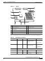
1
C H A P T E R
1
Cisco 7200 VXR Product Overview
This chapter provides physical and functional overviews of the Cisco 7200 VXR routers. Descriptions
and examples of software commands are included when they are necessary for replacing, installing,
configuring, or maintaining the router hardware.
The following sections describe router hardware, major components, and functions of hardware-related
features:
Warning
•
Physical Description, page 1-1
•
Software Requirements, page 1-4
•
Cisco 7204VXR Overview, page 1-4
•
Cisco 7206VXR Overview, page 1-7
•
Field-Replaceable Units, page 1-10
•
Functional Overview, page 1-54
Before you install, operate, or service the system, read the “Site Preparation and Safety” section of the
Regulatory Compliance and Safety Information for the Cisco 7200 Series Routers . This section
contains important safety information you should know before working with the system. Statement 200
Physical Description
The Cisco 7200 VXR routers are the newest, multiservice members of the Cisco 7200 series routers. The
Cisco 7200 VXR routers include the Cisco 7204VXR (4-slot router) and the Cisco 7206VXR (6-slot
router). The Cisco 7200 VXR routers are designed to support gigabit capabilities and to improve data,
voice, and video integration in both service provider and enterprise environments.
The Cisco 7200 VXR routers incorporate an integrated Multiservice Interchange (MIX) capability to
support future voice applications. MIX interconnections on the midplane provide the ability to switch
DS-0 time slots between multichannel T1 or E1 interfaces, much like a digital cross-connect or an
add-drop multiplexer. This feature enables the Cisco 7200 VXR routers to switch DS-0 voice channels
on a T1 or E1 interface from one voice processing port adapter to another voice processing port adapter.
It also enables DS-0s to be switched through the Cisco 7200 VXR routers without any processing, a
requirement in certain voice configurations.
Cisco 7200 VXR Installation and Configuration Guide
OL-5013-08
1-1
Chapter 1
Cisco 7200 VXR Product Overview
Physical Description
The Cisco 7200 VXR routers support the high-speed network processing engine, NPE-G2, and all other
available network processing engines. The NPE-G2 provides high-speed performance with the Motorola
Freescale 7448 1.67-GHz processor and supports three Gigabit Ethernet interfaces with no additional
bandwidth requirements. The NPE-G2 also provides a dedicated Fast Ethernet Management port and two
USB ports for data storage and security tokens.
The Cisco 7200 VXR routers also support high-speed network processing engines (NPEs) to provide
increased routing and process switching performance.
The Cisco 7200 VXR routers with the NPE-G2, NPE-G1, NPE-400, and NSE-1 installed support both
25-MHz and 50-MHz port adapter operation.
Note
For port adapter configuration information, refer to the Cisco 7200 Series Port Adapter Hardware
Configuration Guidelines publication.
The Cisco 7200 VXR routers accommodate a variety of network interface port adapters and I/O
controllers. Because both the NPE-G1 and NPE-G2 contain I/O controller functionality, they can be used
without an I/O controller installed. The NPE-G2 and NPE-G1 provide a third PCI bus, which enables
the Port Adapter Jacket Card to be installed in the I/O controller slot to allow usage of an additional
high-bandwidth-usage port adapter.
A Cisco 7200 VXR router equipped with an NSE-1 or NPE-400 can support up to six high-speed port
adapters and can also support higher-speed port adapter interfaces including Gigabit Ethernet and OC-12
ATM. The Cisco 7200 VXR routers also contain bays for up to two AC-input or DC-input power
supplies.
The port adapters, I/O controller, and power supplies are the same for all Cisco 7200 VXR routers and
are described in the “Field-Replaceable Units” section on page 1-10. The network processing engines
and network services engine are router model specific.
The Cisco 7200 VXR routers support the following features:
•
Online insertion and removal (OIR)—Allows you to add, replace, or remove port adapters without
interrupting the system.
Note
The Port Adapter Jacket Card does not support OIR. However, the port adapter installed in
the Port Adapter Jacket Card does support OIR.
•
Dual hot-swappable, load-sharing power supplies—Provide system power redundancy; if one power
supply or power source fails, the other power supply maintains system power without interruption.
Also, when one power supply is powered off and removed from the router, the second power supply
immediately takes over the router’s power requirements without interrupting normal operation of the
router.
•
Environmental monitoring and reporting functions—Allow you to maintain normal system
operation by resolving adverse environmental conditions prior to loss of operation.
•
Downloadable software—Allows you to load new images into Flash memory remotely, without
having to physically access the router, for fast, reliable upgrades.
Cisco 7200 VXR Installation and Configuration Guide
1-2
OL-5013-08
Chapter 1
Cisco 7200 VXR Product Overview
Physical Description
See Table 1-1 for the Cisco 7200 VXR physical specifications and power requirements:
Table 1-1
Physical Specifications
Description
Specification
Midplane
Two primary PCI buses, and one secondary PCI bus
•
With an NPE-G2 or NPE-G1 and an I/O controller installed, the I/O controller does not use
bandwidth points, and the NPE-G2 or NPE-G1 does use bandwidth points. The NPE-G2 or
NPE-G1 does not use bandwidth points if installed without the I/O controller.
•
With an NSE-1, NPE-400, or NPE-300 installed: aggregate bandwidth of 900 Mbps1
•
With n NPE-100, NPE-150, or NPE-200 installed: aggregate bandwidth of 600 Mbps
Three primary PCI buses—With the NPE-G2 or NPE-G1 installed, no I/O controller, and the Port
Adapter Jacket Card installed, three PCI buses are available. Aggregate bandwidth of the PCI buses
is 900 Mbps. The third PCI bus goes to the Port Adapter Jacket Card and provides unlimited
bandwidth for one port adapter.
Dimensions
(H x W x D)
5.25 in. x 16.8 in. x 17 in. (13.34 cm x 42.67 cm x 43.18 cm)
Weight
Chassis fully configured with a network processing engine or network services engine, I/O
controller, maximum number of port adapters, 2 power supplies, and a fan tray: ~ 50 lb (22.7 kg)
Heat dissipation
370W (1262 BTU2)
Chassis fan noise
levels—single speed
fan
Tested:
•
Front (I/O controller and port adapter side) 44.2 dB
•
Back (power supply side) 43.7 dB
•
Left (fan side) 47.2 dB
•
Right 44.8 dB
Maximum: 65 dBa
Airflow
~80 cfm3
Temperature
32 to 104 F (0 to 40 C) operating; –4 to 149 F (–20 to 65 C) nonoperating
Humidity
10 to 90% noncondensing
Power Specifications
AC-input voltage rating 100–240 VAC4 wide input with power factor correction
AC-input current rating 5A5 at 100–240 VAC with the chassis fully configured
AC-input frequency
rating
50/60 Hz6
AC-input cable
18 AWG7 three-wire cable, with a three-lead IEC-320 receptacle on the power supply end, and a
country-dependent plug on the power source end
DC-output power
280W maximum (with either a single or dual power supply configuration)
DC-input voltage rating –48 VDC8 nominal in North America
–60 VDC nominal in the European Community
Cisco 7200 VXR Installation and Configuration Guide
OL-5013-08
1-3
Chapter 1
Cisco 7200 VXR Product Overview
Software Requirements
Table 1-1
Physical Specifications (continued)
Description
Specification
DC-input current rating 13A at –48 VDC (370W/–48 VDC = 7.7A typical draw)
8A at –60 VDC (370W/–60 VDC = 6.2A typical draw)
DC-input cable
In accordance with local and national wiring regulations
1. Mbps = megabits per second
2. BTU = British thermal units
3. cfm = cubic feet per minute
4. VAC = volts alternating current
5. A = amperes
6. Hz = hertz
7. AWG = American Wire Gauge
8. VDC = volts direct current
Note
For a chassis footprint, additional dimensions, and clearance requirements for the Cisco 7200 VXR
routers, see the “Site Requirement Guidelines” section on page 2-3 in Chapter 2, “Preparing for
Installation.”
Software Requirements
Recommended minimum software requirements:
•
Cisco IOS Release 12.0(2)XE2 or later releases of 12.0XE
•
Cisco IOS Release 12.1(1)E or later releases of 12.1E
•
Cisco IOS Release 12.0(5)S or later releases of 12.0S
•
Cisco IOS Release 12.0(3)T or later releases of 12.0T
•
Cisco IOS Release 12.2(1) or later releases of 12.2
•
Cisco IOS Release 12.2(4)B or later releases of 12.2B
•
Cisco IOS Release 12.4(7)
•
Cisco IOS Release 12.4(4)XD
See Software Advisor at Cisco.com for supported hardware and software releases.
Cisco 7204VXR Overview
The Cisco 7204VXR supports multiprotocol, multimedia routing and bridging with a wide variety of
protocols and port adapter combinations available for Cisco 7200 series routers. In addition, the
Cisco 7204VXR midplane provides increased support for multiple high-bandwidth port adapters.
The Cisco 7204VXR has four slots (slot 1 through slot 4) for port adapters, one slot for an input/output
(I/O) controller, and one slot for a network processing engine or network services engine. You can place
the port adapters in any of the four available slots. (See Figure 1-1.)
Cisco 7200 VXR Installation and Configuration Guide
1-4
OL-5013-08
Chapter 1
Cisco 7200 VXR Product Overview
Cisco 7204VXR Overview
With the NPE-G1 or NPE-G2 installed and the Port Adapter Jacket Card installed in the I/O controller
slot, an additional port adapter slot is available.
Note
If you have difficulty installing a processing engine or I/O controller in the lowest slot of a
Cisco 7200 VXR router that is rack-mounted, remove the port adapters, processing engine and I/O
controller from the chassis and reinstall them. Install the processing engine and I/O controller in the
lowest slots first, then populate the slots above them, in a bottom-to-top order.
Figure 1-1
Cisco 7204VXR Router—Front View
1
Cisco 7200 SERIES XVR
FAST ETHERNET
4
K
RJ4
0
LIN
MII
5
D
LE
AB
EN
3
3
2
2
1
0
LINK
1
0
3
EN
AB
LE
D
ETHERNET 10BT
TX
0
D
LE
AB
O PW
K R
15889
1O
M
E II
N
R
E J4
N 5
R
L J4
IN 5
K
T
0
T
EC
O
SL
EJ
PC
M
C
IA
EN
3
4
Note
2
RX
4
TX
3
PU
C
R
J-
45
FE
R
M
RX
RX
ET
FAST ETHERNET INPUT/OUTPUT CONTROLLER
ES
II
1
T
O
SL
2
1
TX
RX
TX
EN
RX
0
7
6
5
4
3
2
1
0
EN
1
2
TX
ETHERNET-10BFL
SERIAL-EIA/TIA-232
5
6
7
1
Port adapters
5
Optional Fast Ethernet interface (MII port and
RJ-45 port)
2
Port adapter lever
6
Auxiliary port
3
I/O controller
7
Console port
4
PC Card slots
In Figure 1-1, a blank port adapter is installed in slot 3. To ensure adequate airflow across the port
adapters, each port adapter slot must be filled with either a port adapter or a blank port adapter.
The rear of the Cisco 7204VXR router provides access to the network processing engine or network
services engine and up to two power supplies. (See Figure 1-2.)
Cisco 7200 VXR Installation and Configuration Guide
OL-5013-08
1-5
Chapter 1
Cisco 7200 VXR Product Overview
Cisco 7204VXR Overview
Figure 1-2
Cisco 7204VXR Router—Rear View
3
4
2
5
84396
1
NETWORK PROCESSING ENGINE-300
6
7
8
9
1
Chassis grounding receptacles
6
Network processing engine or network
services engine
2
Power supply filler plate
7
AC-input power supply
3
Power switch
8
PWR OK LED
4
AC power cable-retention clip
9
AC power supply receptacle
5
Internal fans
The NPE-G2 and NPE-G1 have external connectors and status LEDs for the three Gigabit Ethernet
interfaces as well as console and auxiliary ports. The network processing engines NPE-100 through
NPE-400 or network services engine (NSE-1) have no external connectors or LEDs. There is a handle
for removing and installing the network processing engine or network services engine and two captive
installation screws for securing it to the chassis.
The Port Adapter Jacket Card is supported in the I/O controller slot.
The Cisco 7204VXR router comes equipped with one 280W AC-input power supply. (A 280W DC-input
power supply option is available.) In Figure 1-2, a Cisco 7204VXR router is configured with a single
AC-input power supply. (A power supply filler plate is installed over the second power supply bay.) A
fully configured Cisco 7204VXR router operates with only one installed power supply; however, a
second, optional power supply of the same type provides hot-swappable, load-sharing, redundant power.
Note
The Cisco 7204VXR does not support a mixture of AC- and DC-input power.
The power supply has the router’s main power switch and either an AC-input power receptacle or a
hardwired DC-input power cable (depending on the type of installed power supply).
Caution
Do not mix power supplies in the Cisco 7204VXR. In dual power supply router configurations, both
power supplies must be of the same type (two AC-input power supplies or two DC-input power supplies).
Adjacent to the power supply bays are two chassis grounding receptacles that provide a chassis ground
connection for ESD equipment or a two-hole grounding lug. (See Figure 1-2.)
Cisco 7200 VXR Installation and Configuration Guide
1-6
OL-5013-08
Chapter 1
Cisco 7200 VXR Product Overview
Cisco 7206VXR Overview
Three internal fans draw cooling air into the chassis and across internal components to maintain an
acceptable operating temperature. (See Figure 1-2.) The three fans are enclosed in a tray that is located
inside the chassis.
Caution
To ensure the proper flow of cooling air across the internal components, make sure blank port adapters
are installed in unoccupied port adapter slots, and power supply filler plates are installed in unoccupied
power supply bays.
The I/O controller, port adapters, Port Adapter Jacket Card, power supplies, and network processing
engine or network services engine slide into their respective chassis slots and connect directly to the
routers midplane; there are no internal cables to connect. The midplane distributes power from the power
supplies to the I/O controller, port adapters, Port Adapter Jacket Card, fan tray, and network processing
engine or network services engine.
The midplane also senses OIR of the port adapters, bridges the PCI buses from the port adapters to
packet memory on the network processing engine or network services engine, arbitrates traffic across
the PCI buses, and generates the clock signals for the port adapters on each PCI bus.
Note
The Port Adapter Jacket Card does not support OIR. However, the port adapter installed in the Port
Adapter Jacket Card does support OIR.
The Cisco 7204VXR operates as either a tabletop or a rack-mounted unit. A rack-mount kit is standard
equipment included with all Cisco 7200 VXR routers when they are shipped from the factory. The kit
provides the hardware needed to mount the router in a standard 19-inch equipment rack or a 2-post rack.
Steps for installing the Cisco 7204VXR router in an equipment rack are the same for all Cisco 7200
VXR routers and are explained in Chapter 3, “Installing a Cisco 7200 VXR Router.” If you are not
rack-mounting your Cisco 7204VXR, place it on a sturdy tabletop or platform.
A fully configured Cisco 7204VXR, with two installed power supplies and all chassis slots filled, weighs
approximately 50 pounds (22.7 kilograms [kg]). For clearance requirements and rack-mount installation
considerations, see Chapter 2, “Preparing for Installation,” the “Site Requirement Guidelines” section
on page 2-3.
Cisco 7206VXR Overview
The Cisco 7206VXR supports multiprotocol, multimedia routing and bridging with a wide variety of
protocols and port adapter combinations available for Cisco 7200 series routers. In addition, the
Cisco 7206VXR midplane provides increased support for multiple high-bandwidth port adapters.
Note
The Cisco 7206VXR is also available as a router shelf in a Cisco AS5800 Universal Access Server. If
your Cisco 7206VXR is installed as a router shelf, use this publication in conjunction with the
Cisco AS5800 Universal Access Server publications that shipped with the access server.
The Cisco 7206VXR has six slots (slot 1 through slot 6) for port adapters, one slot for an input/output
(I/O) controller, and one slot for a network processing engine or network services engine. You can place
the port adapters in any of the six available slots.
The front of the Cisco 7206VXR provides access to the I/O controller and up to six network interface
port adapters. (See Figure 1-3.)
Cisco 7200 VXR Installation and Configuration Guide
OL-5013-08
1-7
Chapter 1
Cisco 7200 VXR Product Overview
Cisco 7206VXR Overview
With the NPE-G1 or NPE-G2 installed and the Port Adapter Jacket Card installed in the I/O controller
slot, an additional port adapter slot is available.
Note
If you have difficulty installing a processing engine or I/O controller in the lowest slot of a
Cisco 7200 VXR router that is rack-mounted, remove the port adapters, processing engine and I/O
controller from the chassis and reinstall them. Install the processing engine and I/O controller in the
lowest slots first, then populate the slots above them, in a bottom-to-top order.
Figure 1-3
Cisco 7206VXR Router—Front View
2
1
3
2
1
0
6
TOKEN RING
5
FAST ETHERNET
5
4
K
RJ4
LIN
MII
0
ET
ES
2
TX
RX
4
TX
RX
PU
C
AB
LE
D
0
R
J-
45
FE
R
M
3
TX
RX
2
RX
1
TX
II
1
T
O
SL
FAST ETHERNET INPUT/OUTPUT CONTROLLER
O PW
K R
84517
1O
R
E J4
N 5
R
L J4
IN 5
K
M
E II
N
0
T
EC
O
EJ
C
M
PC
SL
IA
T
EN
Cisco 7200
Series VXR
TX
EN
0
RX
CD
LB
RC
RD
TC
TD
CD
LB
RC
RD
TC
TD
CD
LB
RC
RD
TC
TD
CD
LB
EN
RC
RD
TC
TD
1
4
D
ETHERNET-10BFL
FAST SERIAL
3
LE
AB
EN
3
3
2
2
1
0
LINK
1
0
3
EN
AB
LE
D
ETHERNET 10BT
5
Note
6
7
8
1
Blank port adapter
5
PC Card slots
2
Port adapters
6
Optional Fast Ethernet interface (MII port and
RJ-45 port)
3
Port adapter lever
7
Auxiliary port
4
I/O controller
8
Console port
In Figure 1-3, a blank port adapter is installed in slot 5. To ensure adequate airflow across the port
adapters, each port adapter slot must be filled with either a port adapter or a blank port adapter.
Cisco 7200 VXR Installation and Configuration Guide
1-8
OL-5013-08
Chapter 1
Cisco 7200 VXR Product Overview
Cisco 7206VXR Overview
Figure 1-4
Cisco 7206VXR Router—Rear View
3
4
2
5
84396
1
NETWORK PROCESSING ENGINE-300
6
7
8
9
1
Chassis grounding receptacles
6
Network processing engine or network
services engine
2
Power supply filler plate
7
AC-input power supply
3
Power switch
8
PWR OK LED
4
AC power cable-retention clip
9
AC power supply receptacle
5
Internal fans
The rear of the Cisco 7206VXR router provides access to the network processing engine or network
services engine and up to two power supplies. (See Figure 1-4.)
The NPE-G2 and NPE-G1 have external connectors and status LEDs for the three Gigabit Ethernet
interfaces as well as console and auxiliary ports. The network processing engines NPE-100 through
NPE-400 or network services engine (NSE-1) have no external connectors or LEDs. There is a handle
for removing and installing the network processing engine or network services engine and two captive
installation screws for securing it to the chassis.
The Port Adapter Jacket Card is supported in the I/O controller slot.
The Cisco 7206VXR router comes equipped with one 280W AC-input power supply. (A 280W DC-input
power supply option is available.) In Figure 1-4, a Cisco 7206VXR router is configured with a single
AC-input power supply. (A power supply filler plate is installed over the second power supply bay.) A
fully configured Cisco 7206VXR router operates with only one installed power supply; however, a
second, optional power supply of the same type provides hot-swappable, load-sharing, redundant power.
Note
The Cisco 7206VXR does not support a mixture of AC- and DC-input power.
The power supply has the router’s main power switch and either an AC-input power receptacle or a
hardwired DC-input power cable (depending on the type of installed power supply).
Caution
Do not mix power supplies in the Cisco 7206VXR. In dual power supply router configurations, both
power supplies must be of the same type (two AC-input power supplies or two DC-input power supplies).
Cisco 7200 VXR Installation and Configuration Guide
OL-5013-08
1-9
Chapter 1
Cisco 7200 VXR Product Overview
Field-Replaceable Units
Adjacent to the power supply bays are two chassis grounding receptacles that provide a chassis ground
connection for ESD equipment or a two-hole grounding lug. (See Figure 1-4.)
Three internal fans draw cooling air into the chassis and across the internal components to maintain an
acceptable operating temperature. (See Figure 1-4.) The three fans are enclosed in a tray that is located
inside the chassis.
Caution
To ensure the proper flow of cooling air across the internal components, make sure blank port adapters
are installed in unoccupied port adapter slots, and power supply filler plates are installed in unoccupied
power supply bays.
The I/O controller, port adapters, Port Adapter Jacket Card, power supplies, and network processing
engine or network services engine slide into their respective chassis slots and connect directly to the
router’s midplane; there are no internal cables to connect. The midplane distributes power from the
power supplies to the I/O controller, port adapters, Port Adapter Jacket Card, fan tray, and network
processing engine or network services engine.
The midplane also senses OIR of the port adapters, bridges the PCI buses from the port adapters to
packet memory on the network processing engine or network services engine, arbitrates traffic across
the PCI buses, and generates the clock signals for the port adapters on each PCI bus.
Note
The Port Adapter Jacket Card does not support OIR. However, the port adapter installed in the Port
Adapter Jacket Card does support OIR.
The Cisco 7206VXR operates as either a tabletop or a rack-mounted unit. A rack-mount kit is standard
equipment included with all Cisco 7200 VXR routers when they are shipped from the factory. The kit
provides the hardware needed to mount the router in a standard 19-inch equipment rack or a 2-post rack.
Steps for installing the Cisco 7206VXR router in an equipment rack are the same for all Cisco 7200
VXR routers and are explained in Chapter 3, “Installing a Cisco 7200 VXR Router.” If you are not
rack-mounting your Cisco 7206VXR, place it on a sturdy tabletop or platform.
A fully configured Cisco 7206VXR, with two installed power supplies and all chassis slots filled, weighs
approximately 50 pounds (22.7 kilograms [kg]). For clearance requirements and rack-mount installation
considerations, see Chapter 2, “Preparing for Installation,” the “Site Requirement Guidelines” section
on page 2-3.
Field-Replaceable Units
The Cisco 7200 VXR routers are easy to service; many of their major components are field-replaceable
units (FRUs). The following sections describe Cisco 7200 VXR router FRUs:
•
Network Processing Engine or Network Services Engine, page 1-11
•
Input/Output Controller, page 1-32
•
LED Descriptions, page 1-40
•
Port Adapters and Service Adapters, page 1-47
•
Port Adapter Jacket Card, page 1-48
•
Power Supplies, page 1-49
•
Chassis, page 1-51
Cisco 7200 VXR Installation and Configuration Guide
1-10
OL-5013-08
Chapter 1
Cisco 7200 VXR Product Overview
Field-Replaceable Units
Note
•
CompactFlash Disks, Flash Disks, and PC Cards, page 1-52
•
Rack-Mount and Cable-Management Kit, page 1-53
Replacement instructions for removing and replacing FRUs are contained in separate online documents.
For example, if you need to replace an AC power supply in your Cisco 7200 VXR router, refer to the
280-Watt AC-Input Power Supply Replacement Instructions publication. Replacement instructions are
available on the Documentation DVD and on Cisco.com.
Network Processing Engine or Network Services Engine
The network processing engine or network services engine maintains and executes the system
management functions for Cisco 7200 VXR routers. Also, the network processing engine or network
services engine shares the system memory and environmental monitoring functions with the I/O
controller.
Because the NPE-G1 and NPE-G2 contain I/O functionality, the Cisco 7200 VXR routers can operate
with no I/O controller with an NPE-G1 or NPE-G2 installed. With both an I/O controller and the
NPE-G1 or NPE-G2 installed, the NPE-G1 or NPE-G2 enhances the I/O controller functionality.
Cisco 7200 VXR routers support nine versions of the network processing engine: NPE-G2, NPE-G1,
NPE-400, NPE-300, NPE-225, NPE-200, NPE-175, NPE-150, and NPE-100. These network processing
engines have the same functionality; however, their performance differs because of the microprocessor
type and the type of memory for packet data (SRAM and DRAM, or SDRAM) that each network
processing engine provides.
Cisco 7200 VXR routers also support the NSE-1, which consists of two modular boards: the processor
engine board and the network controller board. The NSE-1 Parallel eXpress Forwarding (PXF) processor
works with the Route Processor to provide accelerated packet switching, as well as accelerated IP
Layer 3 feature processing.
Note
Detailed instructions for removing and replacing the network processing engines or network services
engine are contained in the online Network Processing Engine and Network Services Engine Installation
and Configuration publication. It is available on the Documentation DVD and on Cisco.com.
The network processing engines and network services engine consist of the following components:
•
Reduced instruction set computing (RISC) microprocessor
– The NPE-G2 uses a Motorola Freescale 7448 microprocessor that operates at an internal clock
speed of 1.67 GHz.
– The NPE-G1 uses a BCM 1250 microprocessor that operates at an internal clock speed of 700 MHz.
– The NSE-1 uses an RM7000 microprocessor that operates at an internal clock speed of
262 MHz.
– The NPE-400 uses an RM7000 microprocessor that operates at an internal clock speed of
350 MHz.
– The NPE-300 uses an RM7000 microprocessor that operates at an internal clock speed of
262 MHz.
– The NPE-225 has an RM5271 microprocessor that operates at an internal clock speed of
262 MHz.
Cisco 7200 VXR Installation and Configuration Guide
OL-5013-08
1-11
Chapter 1
Cisco 7200 VXR Product Overview
Field-Replaceable Units
– The NPE-200 has an R5000 microprocessor that operates at an internal clock speed of
200 MHz.
– The NPE-175 has an RM5270 microprocessor that operates at an internal clock speed of
200 MHz.
– The NPE-100 and NPE-150 have an R4700 microprocessor that operates at an internal clock
speed of 150 MHz.
•
System controller
– The NPE-G2 has one system controller that provides processor access to the three midplane PCI
buses, and also holds the system memory and environmental monitoring functions.
– The NPE-G1 BCM 1250 maintains and executes the system management functions for the
Cisco 7200 VXR routers and also holds the system memory and environmental monitoring
functions.
– The NSE-1 has one system controller that provides processor access to the midplane and single
I/O controller PCI buses. The system controller also allows port adapters on either of the two
midplane PCI buses to access SDRAM.
– The NPE-400 has one system controller that provides system access.
– The NPE-300 has two system controllers that provide processor access to the two midplane and
single I/O controller PCI buses. The system controller also allows port adapters on either of the
two midplane PCI buses to access SDRAM.
– The NPE-175 and NPE-225 have one system controller that provides processor access to the
two midplane and single I/O controller PCI buses. The system controller also allows the
port adapters on either of the two midplane PCI buses to access SDRAM.
– The NPE-100, NPE-150, and NPE-200 have a system controller that uses direct memory access
(DMA) to transfer data between DRAM and packet SRAM on the network processing engine.
•
Upgradable memory modules
– The NPE-G2 uses SDRAM for storing all packets received or sent from network interfaces, The
SDRAM also stores routing tables and network accounting applications. A single SDRAM
memory array in the system allows concurrent access by port adapters and the processor.
– The NPE-G1 uses SDRAM for storing all packets received or sent from network interfaces. The
SDRAM also stores routing tables and network accounting applications. Two independent
SDRAM memory arrays in the system allow concurrent access by port adapters and the
processor.
– The NSE-1 uses SDRAM for providing code, data, and packet storage.
– The NPE-400 uses SDRAM for storing all packets received or sent from network interfaces. The
SDRAM memory array in the system allows concurrent access by port adapters and the
processor.
– The NPE-300 uses SDRAM for storing all packets received or sent from network interfaces. The
SDRAM also stores routing tables and network accounting applications. Two independent
SDRAM memory arrays in the system allow concurrent access by port adapters and the
processor.
– The NPE-175 and NPE-225 use SDRAM for providing code, data, and packet storage.
Cisco 7200 VXR Installation and Configuration Guide
1-12
OL-5013-08
Chapter 1
Cisco 7200 VXR Product Overview
Field-Replaceable Units
– The NPE-100, NPE-150, and NPE-200 use DRAM for storing routing tables, network
accounting applications, packets of information in preparation for process switching, and
packet buffering for SRAM overflow (except in the NPE-100, which contains no packet
SRAM). The standard configuration is 32 MB, with up to 128 MB available through single
in-line memory module (SIMM) upgrades.
•
Packet SRAM for storing packets of information in preparation for fast switching
The NPE-150 has 1 MB of SRAM and the NPE-200 has 4 MB of SRAM. No other network
processing engine or network services engine has SRAM.
•
Cache memory
– The NPE-G2 has two levels of cache: a primary and a secondary cache that are internal to the
microprocessor, with the secondary unified cache for data and instruction.
– The NPE-G1 has two levels of cache: a primary and a secondary cache that are internal to the
microprocessor, with the secondary unified cache for data and instruction.
– The NSE-1 has three levels of cache: a primary and a secondary unified cache that are internal
to the microprocessor, and a tertiary 2-MB external cache.
– The NPE-400 has three levels of cache: a primary and a secondary cache that are internal to the
microprocessor, and a tertiary 4-MB external cache that provides additional high-speed storage
for data and instructions.
– The NPE-300 has three levels of cache: a primary and a secondary cache that are internal to the
microprocessor, and a tertiary 2-MB external cache that provides additional high-speed storage
for data and instructions.
– The NPE-225 has two levels of cache: a primary cache that is internal to the processor and a
secondary 2-MB external cache that provides additional high-speed storage for data and
instructions.
– The NPE-200 has unified cache SRAM that functions as the secondary cache for the
microprocessor. (The primary cache is within the microprocessor.)
– The NPE-175 has two levels of cache: a primary cache that is internal to the processor and a
secondary 2-MB external cache that provides additional high-speed storage for data and
instructions.
– The NPE-150 has unified cache SRAM that functions as the secondary cache for the
microprocessor. (The primary cache is within the microprocessor.)
– The NPE-100 has unified cache SRAM that functions as the secondary cache for the
microprocessor. (The primary cache is within the microprocessor.)
•
Two environmental sensors for monitoring the cooling air as it leaves the chassis
•
Boot ROM for storing sufficient code for booting the Cisco IOS software; the NPE-G2, NPE-G1,
NSE-1, NPE-400, NPE-300, NPE-225, NPE-200, and NPE-175 have boot ROM.
The network processing engines and network services engine perform the following system management
functions:
•
Sending and receiving routing protocol updates
•
Managing tables, caches, and buffers
•
Monitoring interface and environmental status
•
Providing Simple Network Management Protocol (SNMP) management through the console and
Telnet interface
•
Accounting for and switching of data traffic
Cisco 7200 VXR Installation and Configuration Guide
OL-5013-08
1-13
Chapter 1
Cisco 7200 VXR Product Overview
Field-Replaceable Units
•
Booting and reloading images
•
Managing port adapters (recognition and initialization during online insertion and removal)
The following figures and memory tables provide information about your NPE or NSE:
•
NPE-G2 is represented by Figure 1-5. Table 1-3 lists NPE-G2 memory specifications, and Table 1-3
lists memory configurations.
•
NPE-G1 is represented by Figure 1-6. Table 1-4 lists NPE-G1 memory specifications, and Table 1-5
lists memory configurations.
•
NSE-1 is represented by Figure 1-7. Table 1-6 lists NSE-1 memory specifications, and Table 1-7
lists memory configurations.
•
The NPE-400 is represented by Figure 1-8. Table 1-8 lists NPE-400 memory specifications, and
Table 1-9 lists memory configurations.
•
NPE-300 is represented by Figure 1-9. Table 1-10 lists NPE-300 memory specifications, and
Table 1-11 lists memory configurations.
•
NPE-225 is represented by Figure 1-10. Table 1-12 lists NPE-225 memory specifications, and
Table 1-13 lists memory configurations.
•
NPE-200 is represented by Figure 1-11. Table 1-14 lists NPE-200 memory specifications, and
Table 1-15 lists memory configurations.
•
NPE-175 is represented by Figure 1-12. Table 1-16 lists NPE-175 memory specifications, and
Table 1-17 lists memory configurations.
•
NPE-150 is represented by Figure 1-13. Table 1-18 lists NPE-150 memory specifications, and
Table 1-19 lists memory configurations.
•
NPE-100 is represented by Figure 1-14. Table 1-20 lists NPE-100 memory specifications, and
Table 1-21 lists memory configurations.
Cisco 7200 VXR Installation and Configuration Guide
1-14
OL-5013-08
Chapter 1
Cisco 7200 VXR Product Overview
Field-Replaceable Units
Figure 1-5
NPE-G2
1
10
9
2
8
4
3
5
7
149061
6
1
Midplane connectors
6
Flash memory (U13)
2
Boot ROM (U24)
7
DIMM (socket—S1)
3
NVRAM (on bottom of board—U17)
8
Temperature sensor (inlet—U23)
4
Temperature sensor (outlet—U20)
9
Processor (U30)
5
Flash memory (U19)
10 Keying post
Table 1-2 lists the NPE-G2 memory specification, and Table 1-3 lists the factory-installed SDRAM
configurations and their product numbers.
Table 1-2
NPE-G2 Memory Specifications
Memory Type
Size
Quantity
Description
Component Location
on the NPE-G2 Board
SDRAM
1 GB
1
1-GB DDR SDRAM
S1
Boot ROM
512 KB
1
Reprogrammable Boot ROM
U24
for the ROM monitor program
Flash memory 64 MB
(also known
as bootflash)
1
Contains the default boot
helper (boot loader) image
U19 and U13
NVRAM
1
Nonvolatile EPROM for the
system configuration file
U17
2 MB
Cisco 7200 VXR Installation and Configuration Guide
OL-5013-08
1-15
Chapter 1
Cisco 7200 VXR Product Overview
Field-Replaceable Units
Table 1-2
NPE-G2 Memory Specifications (continued)
Memory Type
Size
Quantity
Component Location
on the NPE-G2 Board
Description
Primary cache 32 KB (16 KB —
instruction,
16 KB data)
Motorola Freescale 7448
processor, internal cache
U30
Secondary
cache
1 MB
Motorola Freescale 7448
secondary cache
U30
Table 1-3
NPE-G2 SDRAM Configuration—Configurable Memory Only
—
Total SDRAM
SDRAM Bank
Quantity
1 GB
S1
1-GB DIMM
Figure 1-6
NPE-G1
1
5
2
6
7
8
9
10
3
GIGABIT ETHERNET 0/1
LINK
EN
GBIC
TX
EN
RJ45
NETWORK PROCESSING ENGINE - G1
GIGABIT ETHERNET 0/1
LINK
RX
LINK
RX
GBIC
EN
TX
RJ45
SLOT
ACTIVE
CPU
RESET
RX
GBIC
TX
C O M PA C T F L A S H
POWER
ON
CONSOLE
AUX
66435
GIGABIT ETHERNET 0/1
RJ45
4
1
Midplane connectors
6
Boot ROM
2
Flash memory
7
NVRAM
3
Temperature sensor
8
DIMM 2
4
Processor
9
Temperature sensor
5
Keying post
10
DIMM 1
Table 1-4 lists the NPE-G1 memory specification, and Table 1-5 lists the factory-installed SDRAM
configurations and their product numbers.
Cisco 7200 VXR Installation and Configuration Guide
1-16
OL-5013-08
Chapter 1
Cisco 7200 VXR Product Overview
Field-Replaceable Units
Table 1-4
NPE-G1 Memory Specifications
Component Location
on the NPE-G1
Board
Memory Type
Size
Quantity
Description
SDRAM
128 MB,
256 MB,
512 MB
2
128-MB, 256-MB,
or 512-MB
SODIMMs
J3, J4
Boot ROM
512 KB
1
Reprogrammable
Boot ROM for the
ROM monitor
program
U1
Flash Memory
16 MB
1
Contains the default U25 and U26
boot helper (boot
loader) image
NVRAM
512 KB
1
Nonvolatile
EPROM for the
system
configuration file
U7
Primary cache
32 KB
(16 KB
instruction,
16 KB data)
—
BCM 1250 system,
internal cache
U22
Secondary cache
512 KB
—
BCM 1250 system,
internal, unified
cache
U22
Table 1-5
NPE-G1 SDRAM SODIMM Memory Configurations—Configurable Memory Only
Total SDRAM
SDRAM Bank
Quantity
Product Number
256 MB
J3 and J4
2 128-MB SODIMMs
MEM-NPE-G1-256MB=
512 MB
J3 and J4
2 256-MB SODIMMs
MEM-NPE-G1-512MB=
1 GB
J3 and J4
2 512-MB SODIMMs
MEM-NPE-G1-1GB=
Cisco 7200 VXR Installation and Configuration Guide
OL-5013-08
1-17
Chapter 1
Cisco 7200 VXR Product Overview
Field-Replaceable Units
Figure 1-7
NSE-1
1
8
2
10
3
9
11
12
4
NETWORK PROCESSING ENGINE-200
6
5
66418
13
7
1
Network controller board
8
Midplane connectors
2
Keying post
9
Boot ROM (U1)
3
System controller
10 Temperature sensor
4
Processor engine board
11 SDRAM
5
Captive installation screw
12 Parallel eXpress Forwarding engine (PXF
processor)
6
RM7000 microprocessor
13 Temperature sensor
7
Handle
Table 1-6 lists the NSE-1 memory specifications, and Table 1-7 lists the NSE-1 factory-installed
SDRAM configurations and their product numbers.
Table 1-6
NSE-1 Memory Specifications
Memory Type
Size
Quantity
Description
Location1
SDRAM
128 or 256 MB
1 SDRAM slot
128- or 256-MB DIMM
U15
Boot ROM
512 KB
1
OTP ROM for the ROM
monitor program
U1
Primary cache
16 KB
(instruction),
16 KB (data)
—
RM7000 processor,
primary internal cache
U22
Cisco 7200 VXR Installation and Configuration Guide
1-18
OL-5013-08
Chapter 1
Cisco 7200 VXR Product Overview
Field-Replaceable Units
Table 1-6
NSE-1 Memory Specifications (continued)
Location1
Memory Type
Size
Quantity
Description
Secondary
cache
256 KB
—
RM7000 processor,
U22
internal, unified
instruction and data cache
Tertiary cache
2 MB (fixed)
—
RM7000 processor,
external cache
U7, U9,
U12, U14,
U17
1. Location on processing engine board. See Figure 1-7.
Table 1-7
NSE-1 SDRAM DIMM Memory Configurations
Total SDRAM
SDRAM Bank
Quantity
Product Number
128 MB
U15
1 128-MB DIMM
MEM-SD-NPE-128MB=
256 MB
U15
1 256-MB DIMM
MEM-SD-NSE-256MB=
Figure 1-8
NPE-400
1
7
2
3
8
4
9
10
NETWORK PROCESSING ENGINE-400
5
66411
11
6
1
Temperature sensor (U31)
7
Midplane connector
2
Keying post
8
Boot ROM (U7)
3
RM7000 microprocessor
9
Temperature sensor
4
System controller
10 SODIMM (J1)
5
Captive installation screw
11 Standoff and screw
6
Handle
Cisco 7200 VXR Installation and Configuration Guide
OL-5013-08
1-19
Chapter 1
Cisco 7200 VXR Product Overview
Field-Replaceable Units
Table 1-8 lists the NPE-400 memory specifications, and Table 1-9 lists factory-installed SDRAM
configurations and their product numbers.
Table 1-8
NPE-400 Memory Specifications
Memory Type
Size
Quantity
Description
Location
SDRAM-configurable 128, 256, or
512 MB
1
128-, 256-, or 512-MB
SODIMM
J1
Boot ROM
512 KB
1
OTP1 ROM for the ROM
monitor program
U7
Primary cache
16 KB
(instruction),
16 KB (data)
—
RM7000 processor,
integrated cache
U38
Secondary cache
256 KB (fixed)
—
RM7000 processor, unified, U38
internal cache
Tertiary cache
4 MB (fixed)
—
RM7000 processor, external U2, U26,
cache
U27, U28,
U37
1. OTP = one-time programmable
Table 1-9
NPE-400 SDRAM SODIMM Memory Configurations
Total SDRAM
Bank 1
Quantity
Product Number
128 MB
J1
1 128-MB SODIMM
MEM-NPE-400-128MB=
256 MB
J1
1 256-MB SODIMM
MEM-NPE-400-256MB=
512 MB
J1
1 512 MB SODIMM
MEM-NPE-400-512MB=
Cisco 7200 VXR Installation and Configuration Guide
1-20
OL-5013-08
Chapter 1
Cisco 7200 VXR Product Overview
Field-Replaceable Units
Figure 1-9
NPE-300
1
2
11
12
13
3
4
14
15
5
NETWORK PROCESSING ENGINE-300
6
7
8
66410
16
9 10
1
Midplane connectors
9
2
Keying post
10 Temperature sensor (U42)
3
DIMM 3 (U44)
11 Keying post
4
Bank 1 (user configurable)
12 Temperature sensor
5
DIMM 2 (U45)
13 Boot ROM (U1)
6
Captive installation screw
14 DIMM 0 (U16)
7
Handle
15 Bank 0 (fixed size)
8
System controllers
16 U15 never populated
RM7000 microprocessor
Table 1-10 lists the NPE-300 memory specifications, and Table 1-11 lists factory-installed SDRAM
configurations and their product numbers.
Table 1-10
NPE-300 Memory Specifications
Memory Type
Size
Quantity
Description
Location1
SDRAM
32 to 256 MB
1 configurable2 32-, 64-, or 128-MB DIMMs
bank with 2
(based on maximum SDRAM
SDRAM slots
required)
Bank 1:
U45 and
U443
Boot ROM
512 KB
1
OTP4 ROM for the ROM monitor
program
—
RM7000 processor, internal cache U49
Primary cache 16 KB
(instruction),
16 KB (data)
Socket
U1
Cisco 7200 VXR Installation and Configuration Guide
OL-5013-08
1-21
Chapter 1
Cisco 7200 VXR Product Overview
Field-Replaceable Units
Table 1-10
NPE-300 Memory Specifications (continued)
Memory Type
Size
Quantity
Description
Location1
Secondary
cache
256 KB
—
RM7000 processor, internal,
unified instruction and data cache
U49
Tertiary cache
2 MB (fixed)
—
RM7000 processor, external cache U7, U8,
U9, U10,
U17
1. Location on processing engine board. See Figure 1-9.
2. Bank 0 is used exclusively for packet memory and is not user configurable.
3. Bank 1 contains the Cisco IOS software, processor memory, and packet memory.
4. OTP = one-time programmable
Note
The NPE-300 contains two banks of SDRAM. Both SDRAM banks are used for all packet memory
requirements; however, bank 0 is used exclusively for packet memory and is set at a fixed configuration
in the factory.
Bank 1 contains two user-configurable SDRAM slots, DIMM slot 2 and DIMM slot 3 (see Figure 1-9).
Both slots in bank 1 can be populated by DIMMs of different sizes; however, the size of the DIMM in
slot 2 must be greater than or equal to the size of the DIMM in slot 3, and the size of the DIMM in slot 3
can be zero.
Table 1-11
NPE-300 SDRAM DIMM Memory Configurations
Total SDRAM
SDRAM Bank 11
Quantity
Product Number2
323 MB + 32 MB
U45 (DIMM slot 2
only)
1 32-MB DIMM
MEM-SD-NPE-32MB=
323 MB + 64 MB
U45 and U44
or
2 32-MB DIMMs
or
MEM-SD-NPE-32MB=
U45
1 64-MB DIMM
MEM-SD-NPE-64MB=
U45 and U44
or
2 64-MB DIMMs
or
MEM-SD-NPE-64MB=
U45
1 128-MB DIMM
MEM-SD-NPE-128MB=
U45 and U44
2 128-MB DIMMs
MEM-SD-NPE-128MB=
3
32 MB + 128 MB
323 MB + 256 MB
1. There are two user-upgradable SDRAM slots in bank 1. (Bank 0 is used exclusively for packet memory and is set at a fixed
configuration in the factory.)
2. These products are also available as SDRAM upgrades. To order an upgrade, add an equal sign (=) after the product number,
for example, MEM-SD-NPE-128MB=.
3. This 32 MB is fixed memory in SDRAM bank 0, socket U16. Socket U15 is never populated.
Cisco 7200 VXR Installation and Configuration Guide
1-22
OL-5013-08
Chapter 1
Cisco 7200 VXR Product Overview
Field-Replaceable Units
Figure 1-10
NPE-225
1
7
8
9
2
10
NETWORK PROCESSING ENGINE-200
4
5
66417
3
6
1
Network controller board
6
Handle
2
System controller
7
Midplane connectors
3
Processor engine board
8
Boot ROM (U1)
4
Captive installation screw
9
Temperature sensor
5
RM5271 microprocessor
10 SDRAM DIMM (U15)
Table 1-12 lists the NPE-225 memory specifications, and Table 1-13 lists factory-installed SDRAM
configurations and their product numbers.
Cisco 7200 VXR Installation and Configuration Guide
OL-5013-08
1-23
Chapter 1
Cisco 7200 VXR Product Overview
Field-Replaceable Units
Table 1-12
NPE-225 Memory Specifications
Memory Type
Size
Quantity
Description
Location1
SDRAM
64, 128, 256 MB
1 SDRAM slot
64-MB, 128- MB,
or 256-MB
SDRAM DIMM
U15
Boot ROM
512 KB
—
One-time
programmable
ROM
U1
Primary cache
16 KB (instruction), —
16 KB (data)
RM527x
U4
processor, internal
cache
32 KB (instruction), —
32 KB (data)
RM527x
U4
processor, internal
cache
2 MB
RM527x
processor, unified
external cache
Secondary cache
4 chips, each 512K
by 8 bits wide
U5, U6, U7, U8
1. Location on processing engine board. See Figure 1-10.
Table 1-13
NPE-225 SDRAM DIMM Memory Configurations
Total SDRAM
Bank
Quantity
Product Number
64 MB
U15
1 64-MB DIMM
MEM-SD-NPE-64MB=
128 MB
U15
1 128-MB DIMM
MEM-SD-NPE-128MB=
256 MB
U15
1 256-MB DIMM
MEM-SD-NSE-256MB=
Cisco 7200 VXR Installation and Configuration Guide
1-24
OL-5013-08
Chapter 1
Cisco 7200 VXR Product Overview
Field-Replaceable Units
Figure 1-11
NPE-200
7
8
9
10
1
U52
11
U42
2
U25
12
3
NETWORK PROCESSING ENGINE-200
4
66420
U11
6
5
1
System controller
7
Midplane connectors
2
R5000 microprocessor
8
Temperature sensor
3
4-MB SRAM (U6, U10, U13, U14, U28, U29, 9
U38, and U39)
4
Captive installation screw
10 DRAM SIMMs
5
Handle
11 Bank 1
6
Temperature sensor
12 Bank 2
Boot ROM (U92)
Table 1-14 lists the NPE-200 memory specifications, and Table 1-15 lists factory-installed DRAM
configurations and their product numbers.
Table 1-14
NPE-200 Memory Specifications
Memory Type
Size
Quantity
Description
Location1
DRAM
32 to 128 MB
2 to 4
16- or 32-MB
SIMMs (based
on maximum
DRAM required)
Bank 0: U11 and
U25
Bank 1: U42 and
U52
SRAM
4 MB
8
8 chips, each
being 512K
words x 8 bits
wide
U6, U10, U13,
U14, U28, U29,
U38, and U39
Boot ROM2
256 KB
1
EPROM for the
ROM monitor
program
U92
Cisco 7200 VXR Installation and Configuration Guide
OL-5013-08
1-25
Chapter 1
Cisco 7200 VXR Product Overview
Field-Replaceable Units
Table 1-14
NPE-200 Memory Specifications (continued)
Location1
Memory Type
Size
Quantity
Description
Primary cache
—
—
R5000 processor, U44
internal cache
Secondary cache
512 KB
4
R5000 processor, U16, U9, U109,
unified external and U107
cache
1. Location on processing engine board. See Figure 1-11.
2. ROM = read-only memory
Note
To prevent DRAM errors in the NPE-100, NPE-150, or NPE-200, and to ensure that your system
initializes correctly at startup, DRAM bank 0 (socket U18 and U25, or U11 and U25) must contain no
fewer than two SIMMs of the same type. You may also install two SIMMs of the same type in bank 1
(socket U4 and U12, or U42 and U52); however, bank 0 must always contain the two largest size SIMMs.
Table 1-15
NPE-200 DRAM SIMM Memory Configurations
Total
DRAM
DRAM Bank 0 Quantity
DRAM Bank 1
Quantity
Product Number1
32 MB
U11 and U25 2 16-MB SIMMs
U42 and U52
—
MEM-NPE-32MB=
64 MB
U11 and U25 2 32-MB SIMMs
U42 and U52
—
MEM-NPE-64MB=
128 MB
U11 and U25 2 32-MB SIMMs
U42 and U52
2 32-MB
SIMMs
MEM-NPE-128MB=
1. These products are also available as DRAM upgrades. For example to upgrade a network processing engine from 32 MB to
64 MB of DRAM, order product number MEM-NPE-64MB=.
Cisco 7200 VXR Installation and Configuration Guide
1-26
OL-5013-08
Chapter 1
Cisco 7200 VXR Product Overview
Field-Replaceable Units
Figure 1-12
NPE-175
1
7
8
9
2
10
NETWORK PROCESSING ENGINE-150
4
5
66416
3
6
1
Network controller board
6
Handle
2
System controller
7
Midplane connectors
3
Processor engine board
8
Boot ROM (U1)
4
Captive installation screw
9
Temperature sensor
5
RM5270 microprocessor
10 SDRAM DIMM (U15)
Table 1-16 lists the NPE-175 memory specifications, and Table 1-17 lists memory configurations.
Cisco 7200 VXR Installation and Configuration Guide
OL-5013-08
1-27
Chapter 1
Cisco 7200 VXR Product Overview
Field-Replaceable Units
Table 1-16
NPE-175 Memory Specifications
Memory Type
Size
Quantity
Description
Location1
SDRAM
64 or 128 MB
1 SDRAM slot
DIMM
U15
Boot ROM
512 KB
—
One-time
programmable
ROM
U1
Primary cache
16 KB (instruction),
16 KB (data)
—
RM527x processor, U4
internal cache
32 KB (instruction),
32 KB (data)
—
RM527x processor, U4
internal cache
2 MB
4 chips, each 512K RM527x processor, U5, U6, U7, U8
by 8 bits wide
unified external
cache
Secondary cache
1. Location on processing engine board. See Figure 1-12.
Table 1-17
NPE-175 SDRAM DIMM Memory Configurations
Total SDRAM
SDRAM Bank
Quantity
Product Number
64 MB
U15
1 64-MB
DIMM
MEM-SD-NPE-64MB=
128 MB
U15
1 128-MB
DIMM
MEM-SD-NPE-128MB=
Cisco 7200 VXR Installation and Configuration Guide
1-28
OL-5013-08
Chapter 1
Cisco 7200 VXR Product Overview
Field-Replaceable Units
Figure 1-13
NPE-150
7
8
9
1
U12
10
U4
2
U25
11
3
NETWORK PROCESSING ENGINE-150
4
66424
U18
6
5
1
System controller
7
Midplane connectors
2
R4700 microprocessor
8
Temperature sensor
3
1-MB SRAM (U700 through U703, U800
through U803)
9
DRAM SIMMs
4
Captive installation screw
10 Bank 1
5
Handle
11 Bank 0
6
Temperature sensor
Table 1-18 lists the NPE-150 memory specifications, and Table 1-19 lists memory configurations.
Table 1-18
NPE-150 Memory Specifications
Location1
Memory Type
Size
Quantity
Description
DRAM
32 to 128 MB
2 to 4
16- or 32-MB SIMMs (based Bank 0: U18 and
on maximum DRAM
U25
required)
Bank 1: U4 and
U12
SRAM
1 MB
8
8 chips, each being 128K
words x 9 bits wide
Boot ROM
The NPE-150 uses the boot ROM present on the I/O controller.
Primary cache
—
—
R4700 processor, internal
cache
U201
Secondary cache
512 KB
4
R4700 processor, unified
external cache
U2, U10, U14,
and U26
U700 through
U703
U800 through
U803
1. Location on processing engine board. See Figure 1-13.
Cisco 7200 VXR Installation and Configuration Guide
OL-5013-08
1-29
Chapter 1
Cisco 7200 VXR Product Overview
Field-Replaceable Units
Note
To prevent DRAM errors in the NPE-100, NPE-150, or NPE-200, and to ensure that your system
initializes correctly at startup, DRAM bank 0 (socket U18 and U25, or U11 and U25) must contain no
fewer than two SIMMs of the same type. You may also install two SIMMs of the same type in bank 1
(socket U4 and U12, or U42 and U52); however, bank 0 must always contain the two largest size SIMMs.
Table 1-19
NPE-150 DRAM SIMM Memory Configurations
Total DRAM
DRAM Bank 0
Quantity
DRAM Bank 1
Quantity
Product Number1
32 MB
U18 and U25
2 16-MB SIMMs
U4 and U12
—
MEM-NPE-32MB=
64 MB
U18 and U25
2 32-MB SIMMs
U4 and U12
—
MEM-NPE-64MB=
128 MB
U18 and U25
2 32-MB SIMMs
U4 and U12
2 32-MB
SIMMs
MEM-NPE-128MB=
1. These products are also available as DRAM upgrades. For example, to upgrade a network processing engine from 32 MB to
64 MB of DRAM, order product number MEM-NPE-64MB=.
Figure 1-14
NPE-100
6
7
8
1
U12
9
U4
2
U25
10
NETWORK PROCESSING ENGINE-100
3
4
66433
U18
5
1
System controller
6
Midplane connectors
2
R4700 microprocessor
7
Temperature sensor
3
Captive installation screw
8
DRAM SIMMs
4
Handle
9
Bank 1
5
Temperature sensor
10 Bank 0
Table 1-20 lists the NPE-100 network processing engine memory specifications, and Table 1-21 lists
memory configurations.
Cisco 7200 VXR Installation and Configuration Guide
1-30
OL-5013-08
Chapter 1
Cisco 7200 VXR Product Overview
Field-Replaceable Units
Table 1-20
NPE-100 Memory Specifications
Memory Type
Size
Quantity
Description
Location1
DRAM
32 to
128 MB
2 to 4
16- or 32-MB SIMMs (based
on maximum DRAM
required)
Bank 0: U18 and U25
Bank 1: U4 and U12
Boot ROM
The NPE-100 uses boot ROM present on the I/O controller.
Primary cache
—
—
R4700 processor, internal
cache
U201
Secondary
cache
512 KB
4
R4700 processor, unified,
external cache
U2, U10, U14, and U26
1. Location on processing engine board. See Figure 1-14.
Note
To prevent DRAM errors in the NPE-100, NPE-150, or NPE-200, and to ensure that your system
initializes correctly at startup, DRAM bank 0 (socket U18 and U25, or U11 and U25) must contain no
fewer than two SIMMs of the same type. You may also install two SIMMs of the same type in bank 1
(socket U4 and U12, or U42 and U52); however, bank 0 must always contain the two largest size SIMMs.
Table 1-21
NPE-100 DRAM SIMM Memory Configurations
Total DRAM
DRAM Bank 0
Quantity
DRAM Bank 1 Quantity
Product Number1
32 MB
U18 and U25
2 16-MB
SIMMs
U4 and U12
—
MEM-NPE-32MB
64 MB
U18 and U25
2 32-MB
SIMMs
U4 and U12
—
MEM-NPE-64MB
128 MB
U18 and U25
2 32-MB
SIMMs
U4 and U12
2 32-MB
SIMMs
MEM-NPE-128MB
1. These products are also available as DRAM upgrades. For example, to upgrade a network processing engine from 32 MB to
64 MB of DRAM, order product number MEM-NPE-64MB=.
To determine the memory configuration of your Cisco 7200 VXR router, use the show version
command. The following example shows an NPE-G1 installed in a Cisco7206VXR router:
Router# show version
Cisco Internetwork Operating System Software
IOS (tm) 7200 Software (C7200-JS-M),
Released Version 12.2(20011220:181136) [biff]
Copyright (c) 1986-2001 by cisco Systems, Inc.
Compiled Fri 21-Dec-01 05:58 by
Image text-base:0x600089B8, data-base:0x6196E000
ROM:System Bootstrap, Version 12.2(20011219:132854)
(display text omitted)
cisco 7206VXR (NPE-G1) processor (revision 0x00) with 245760K/16384K bytes of memory.
Processor board ID 13250983
BCM12500 CPU at 500Mhz, Implementation 1, Rev 0.1, 512KB L2 Cache
6 slot VXR midplane, Version 2.0
Cisco 7200 VXR Installation and Configuration Guide
OL-5013-08
1-31
Chapter 1
Cisco 7200 VXR Product Overview
Field-Replaceable Units
Input/Output Controller
This section describes five different models of I/O controllers. These models are distinguished from one
another by their Ethernet interface options. Table 1-22 lists the I/O controllers by product number and
describes their differences.
Note
For a description of the configuration commands you need to configure the different interfaces on your
I/O controller, refer to the Input/Output Controller Replacement Instructions document.
Table 1-22
I/O Controller Descriptions
Product Number
Description
C7200-I/O-GE+E
1 Gigabit Ethernet and 1 Ethernet port; equipped with a GBIC receptacle for
1000 megabits per second (Mbps) operation and an RJ-45 receptacle for
10-Mbps operation. (See Figure 1-15.)
C7200-I/O-2FE/E
2 autosensing Ethernet/Fast Ethernet ports; equipped with 2 RJ-45 receptacles
for 10/100-Mbps operation. (See Figure 1-16.)
C7200-I/O-FE1
1 Fast Ethernet port; equipped with an MII receptacle and an RJ-45 receptacle
for use at 100 Mbps full-duplex or half-duplex operation. Only 1 receptacle
can be configured for use at a time. (See Figure 1-17.)
C7200-I/O
Has no Fast Ethernet port. (See Figure 1-19.)
C7200-I/O-FE-MII
2
1 Fast Ethernet port; equipped with a single MII receptacle. (See Figure 1-21.)
1. The Product Number C7200-I/O-FE does not specify MII because both an MII and an RJ-45 receptacle are included.
2. The I/O controller with the Product Number C7200-I/O-FE-MII has a single MII Fast Ethernet receptacle only. Although still
supported by Cisco Systems, this I/O controller with a single MII receptacle is no longer an orderable product as of May 1998.
You can also identify your I/O controller model from a terminal by using the show diag slot 0 command.
(See the “Viewing Your System Configuration” section on page 4-20.)
The I/O controllers consist of the following components and options:
•
Ethernet, Fast Ethernet, or Gigabit Ethernet interface options
•
Dual channels for local console and auxiliary ports
The console port has full data communications equipment (DCE) functionality and the auxiliary port
has full data terminal equipment (DTE) functionality.
•
NVRAM for storing the system configuration and environmental monitoring logs
Note
NVRAM uses lithium batteries to maintain its contents when disconnected from power.
Some I/O controllers use a static RAM (SRAM) component with an external lithium battery
to provide the same functionality as the NVRAM.
•
Two PC Card (PCMCIA) slots that hold Flash Disks or PC cards for storing the default Cisco IOS
software image
•
Flash memory for storing the boot helper image
•
Boot ROM for storing sufficient code for booting the Cisco IOS software
•
Two environmental sensors for monitoring the cooling air as it enters and leaves the chassis
Cisco 7200 VXR Installation and Configuration Guide
1-32
OL-5013-08
Chapter 1
Cisco 7200 VXR Product Overview
Field-Replaceable Units
Figure 1-15
C7200-I/O-GE+E—With GBIC Gigabit Ethernet and RJ-45 Ethernet Receptacles
1
3
2
6
4
7
5
1
SL
D
LE
AB
T
IA
EC
MC
EJ
PC
OT
0
SL
RT
RX PO E O
G
TX
K
D
1
E L
E
LIN
L E
S
1 TD
A
T
L
C E N
C
U S A
E
D AS Y
D
O L O
D
R K V
E
P IT EC
L
D
VE1
O
E M
T
L T AS
C
1 K IT S
U
S U U LA
D
S D D
O
A O O C
R
L R R E
P
C P P D
K
ETHERNET GIGABIT ETHERNET INPUT/OUTPUT CONTROLLER
LIN
R
PW
IO K
O
U
CP ET
S
RE
RT 0
PO E
E
OL
X
AU
NS
CO
84526
OT
C7200-I/O-GE+E
EN
8
9
10
11
12 13
1
Temperature sensor
8
Captive installation screw
2
Midplane connectors
9
PC Card slots
3
Battery for SRAM
10 Gigabit Ethernet GBIC port
4
8-MB Flash memory (soldered) (U13)
11 Ethernet RJ-45 port
5
8-MB Flash memory (soldered), (U25)
12 Auxiliary port
6
Temperature sensor
13 Console port
7
SRAM (U19)
Figure 1-16
C7200-I/O-2FE/E—With Two RJ-45 Ethernet/Fast Ethernet Receptacles
Cisco 7200 VXR Installation and Configuration Guide
OL-5013-08
1-33
Chapter 1
Cisco 7200 VXR Product Overview
Field-Replaceable Units
1
3
2
6
4
7
5
1
K
K
LIN
SL
DUAL FAST ETHERNET INPUT/OUTPUT CONTROLLER
LIN
D
LE
AB
T
EC
IA
MC
EJ
PC
OT
s
0
SL
bp
0
10
M
E/E
s
bp
0
0
F
10
M
F
E/E
1
R
PW
IO K
O
U
CP ET
S
RE
E
OL
X
AU
NS
CO
84525
OT
C7200-I/O-2FE/E
EN
8
9
11 12
10
1
Temperature sensor
7
SRAM (U19)
2
Midplane connectors
8
Captive installation screw
3
Battery for SRAM
9
PC Card slots
4
8-MB Flash memory (soldered) (U15)
10 RJ-45 Fast Ethernet ports
5
8-MB Flash memory (soldered) (U25)
11 Auxiliary port
6
Temperature sensor
12 Console port
Cisco 7200 VXR Installation and Configuration Guide
1-34
OL-5013-08
Chapter 1
Cisco 7200 VXR Product Overview
Field-Replaceable Units
Figure 1-17
C7200-I/O-FE—With MII and RJ-45 Fast Ethernet Receptacles (Version 1)
2
3
1
5
4
1
LO
S
II
FE
5
J4
N
E
M
FAST ETHERNET INPUT/OUTPUT CONTROLLER
5
J4 K
LIN
R
T
R
E
S
E
U
R
P
D
C
LE
B
A
N
E
T
T
C
IA
JE
C
M
E
C
P
N
0
LO
II
M
S
E
5
R
W
P OK
O
J4
R
LE
X
U
O
A
S
N
I/
O
C
84531
T
6
7
8
12
9
13
11
10
1
Temperature sensor
8
PC Card slots
2
Midplane connectors
9
Optional Fast Ethernet interface (MII port and
RJ-45 port)
3
Flash SIMM (U99)
10 LEDs
4
Boot ROM (U20)
11 CPU reset button
5
NVRAM (U41)
12 Auxiliary port
6
Temperature sensor
13 Console port
7
Captive installation screw
Cisco 7200 VXR Installation and Configuration Guide
OL-5013-08
1-35
Chapter 1
Cisco 7200 VXR Product Overview
Field-Replaceable Units
Figure 1-18
C7200-I/O-FE—With MII and RJ-45 Fast Ethernet Receptacles (Version 2)
1
2
3
4
5
7
8
6
1
II
FE
5
J4
N
E
M
FAST ETHERNET INPUT/OUTPUT CONTROLLER
5
J4 K
LIN
R
T
R
E
S
E
U
84523
T
LO
S
R
P
D
C
LE
B
A
N
E
T
T
C
IA
C
M
C
P
JE
E
R
N
0
II
E
M
LO
S
5
J4
R
I/O
LE
X
W K
O
U
P
O
A
S
N
O
C
9
10
14
11
15
13
12
1
Temperature sensor
9
2
FPGA configuration PROM (U9)
10 PC Card slots
3
Midplane connectors
11 Optional Fast Ethernet interface (MII port and
RJ-45 port)
4
4-MB Flash memory (soldered) (U10–U13)
12 LEDs
5
SRAM (U14)
13 CPU reset button
6
Boot EPROM (U4)
14 Auxiliary port
7
Temperature sensor
15 Console port
8
Battery for SRAM
Captive installation screw
Note
Your I/O controller with the MII and RJ-45 Fast Ethernet receptacles (C7200-I/O-FE) might look like
the first illustration in Figure 1-17, or it might look like Figure 1-18. There is no functional difference
between these two I/O controllers with the Fast Ethernet port.
Note
In Figure 1-17, the NVRAM is replaced by an SRAM component (U14) that is made to act like the
NVRAM by the addition of some external components, one of which is the button-type lithium battery
labeled “Battery for SRAM.”
Note
Your I/O controller without the Fast Ethernet port (C7200-I/O) might look like Figure 1-19, or it might
look like Figure 1-20. There is no functional difference between these two I/O controllers without the
Fast Ethernet port.
Cisco 7200 VXR Installation and Configuration Guide
1-36
OL-5013-08
Chapter 1
Cisco 7200 VXR Product Overview
Field-Replaceable Units
Note
In n Figure 1-20, the NVRAM is replaced by an SRAM component (U14) that is made to act like the
NVRAM by the addition of some external components, one of which is the button-type lithium battery
labeled “Battery for SRAM.”
Figure 1-19
C7200-I/O—Without Fast Ethernet Port (Version 1)
2
3
1
5
4
T
6
1
FAST ETHERNET INPUT/OUTPUT CONTROLLER
LO
T
K
E
T
T
C
IA
JE
C
M
E
C
P
S
E
0
LO
S
U
P
C
R
R
W
P
O
LE
X
U
O
A
S
N
O
IO
C
93277
S
D
LE
B
A
N
E
7
8
10
11
9
1
Temperature sensor
7
Captive installation screw
2
Midplane connectors
8
PC Card slots
3
Flash SIMM (U99)
9
LED and CPU reset button
4
Boot ROM (U20)
10 Auxiliary port
5
NVRAM (U41)
11 Console port
6
Temperature sensor
Cisco 7200 VXR Installation and Configuration Guide
OL-5013-08
1-37
Chapter 1
Cisco 7200 VXR Product Overview
Field-Replaceable Units
Figure 1-20
C7200-I/O—Without Fast Ethernet Port (Version 2)
1
2
3
4
5
7
8
6
T
1
INPUT/OUTPUT CONTROLLER
LO
T
S
E
S
84524
E
U
R
P
D
C
LE
B
A
N
E
T
T
C
IA
C
M
C
P
JE
E
R
0
LO
S
I/O
LE
X
W K
O
U
P
O
A
S
N
O
C
9
10
13
14
12
11
1
Temperature sensor
8
Battery for SRAM
2
FPGA configuration PROM (U9)
9
Captive installation screw
3
Midplane connectors
10 PC Card slots
4
4-MB Flash memory (soldered) (U10–U13)
11 LED
5
SRAM (U14)
12 CPU reset button
6
Boot EPROM (U4)
13 Auxiliary port
7
Temperature sensor
14 Console port
Cisco 7200 VXR Installation and Configuration Guide
1-38
OL-5013-08
Chapter 1
Cisco 7200 VXR Product Overview
Field-Replaceable Units
Figure 1-21
C7200-I/O-FE-MII—With Single MII Fast Ethernet Receptacle
2
3
1
5
4
1
FAST ETHERNET INPUT/OUTPUT CONTROLLER
II
LO
S
FE
M
D
LE
B
A
N
E
LE
T
T
C
IA
JE
C
M
E
C
P
N
LO
E
S
F
E
T
K
B
A
0
E
LIN
F
U
P
C
K
E
S
E
R
R
W
P
O
LE
X
U
O
A
S
N
O
IO
C
84534
T
6
7
8
11
9
Note
12
10
1
Temperature sensor
7
Captive installation screw
2
Midplane connectors
8
PC Card slots
3
Flash SIMM (U99)
9
Optional Fast Ethernet interface (MII
connector)
4
Boot ROM (U20)
10 LEDs and CPU reset button
5
NVRAM (U41)
11 Auxiliary port
6
Temperature sensor
12 Console port
C7200-I/O-FE-MII, although still supported by Cisco Systems, was discontinued as an orderable
product in May 1998.
Table 1-23 lists the I/O controller memory components.
Cisco 7200 VXR Installation and Configuration Guide
OL-5013-08
1-39
Chapter 1
Cisco 7200 VXR Product Overview
Field-Replaceable Units
Table 1-23
I/O Controller Memory Components
Type
Boot ROM
1
Flash memory
Size
Quantity
Memory Description
Model
256 KB
1
32-pin DIP-type
C7200-I/O-FE-MII U20
32-pin DIP-type or
32-pin PLCC-type
C7200-I/O-FE,
C7200-I/O
Contains the default
boot helper image
C7200-I/O-FE-MII U99
4 MB
1
C7200-I/O-FE,
C7200-I/O
Location
U20 or U4
U99
or
U10, U11,
U12, and U13
(soldered)2
8 MB
1
Flash memory
card
16 or
20 MB
Up to 2
Flash Disk
32, 48, or
128 MB
Up to 2
NVRAM
128 KB
1
C7200-I/O-GE+E,
C7200-I/O-2FE/E
U13 and U25
(soldered)2
Contains the default
Cisco IOS image
All models
PC Card slot 0
and slot 1
Nonvolatile EPROM
for the system
configuration file
C7200-I/O-FE-MII U41
C7200-I/O-FE,
C7200-I/O
U41
or
U14
(soldered)3
C7200-I/O-GE+E,
C7200-I/O-2FE/E
U19
(soldered)3
1. The C7200-I/O-GE+E and C7200-I/O-2FE/E do not have a boot ROM component.
2. Some I/O controllers have no Flash SIMM but use a permanently soldered 4-MB or 8-MB Flash memory chip instead. (For
the location of the 4-MB Flash memory chip, see the Figure 1-18 and Figure 1-20. For the location of the 8-MB Flash memory
chip, see Figure 1-15 and Figure 1-16.)
3. The NVRAM on some I/O controllers is replaced by a 32-pin nonsocketed SRAM component that is soldered onto the card.
The SRAM component is made to act like the NVRAM by the addition of some external components, one of which is a 1-inch
(2.54-cm) button-type lithium battery.
LED Descriptions
All I/O controllers have LEDs, and the NPE-G1 and NPE-G2 also have interfaces that have LEDs.
The I/O controller faceplate contains LEDs that indicate system and port status; two additional LEDs
indicate the status of the Flash Disk or Flash memory cards installed in either PC Card slot. A CPU reset
button is located next to the IO POWER OK LED or next to the auxiliary port on the I/O controller
faceplate. The CPU reset button resets the entire system.
The NPE-G2 and NPE-G1 faceplate contains LEDs that indicate system and port status. The RJ-45 and
GBIC or SFP ports share the same LINK LED because only one of these ports per interface (0/1, 0/2, or
0/3) can be used at any one time. The ENABLE LED is on if the RJ-45 port is in use. The POWER ON
LED on the NPE-G1 or the PWR OK LED on the NPE-G2 is on when the system is powered on, whether
Cisco 7200 VXR Installation and Configuration Guide
1-40
OL-5013-08
Chapter 1
Cisco 7200 VXR Product Overview
Field-Replaceable Units
or not an I/O controller is in the system with the NPE-G1 or NPE-G2. The SLOT ACTIVE LED is on if
there is a CompactFlash Disk in the NPE-G1. The CF ACTV LED is on if there is a CompactFlash Disk
in the NPE-G2.
Caution
To prevent system errors and problems, use the CPU reset button only at the direction of your service
representative.
Table 1-24 lists LEDs common to all models of I/O controllers and describes their functions. Table 1-25
lists LEDs on the NPE-G2.
Note
LEDs are either on or off. The LED state (on or off), not the color, determines the status of connection.
However, most LEDs are green when on, with the exception of the IO POWER OK LED, which is amber
when in the on state. However, with the introduction of the NPE-G2, flashing LEDs are also indicative
of activity.
Table 1-24
I/O Controller LEDs
LED
Color
Function
ENABLED
Green
Indicates that the network processing engine or network services engine
and the I/O controller are enabled for operation by the system; however, it
does not mean that the Fast Ethernet port on the I/O controller is functional
or enabled. This LED goes on during a successful router boot and remains
on during normal operation of the router.
IO POWER
OK
Amber
Indicates that the I/O controller is on and receiving DC power from the
router midplane. This LED comes on during a successful router boot and
remains on during normal operation of the router.
Slot 0
Green
These LEDs indicate which PC Card slot is in use by coming on when
either slot is being accessed by the system. These LEDs remain off during
normal operation of the router.
Slot 1
NPE-G2 LEDs
Table 1-25
LED Label
NPE-G2 LEDs
Color
Status in the Power Up State
LINK ACTV
RJ-45 and SFP
(Interfaces 0/1, 0/2, ports
0/3)
Solid green
Link with no activity.
Flashing green
Link with activity.
Off
No link.
EN (Enable)
RJ-45 ports only
(Interfaces 0/1, 0/2,
0/3)
Solid green
RJ-45 port is selected.
Off
SFP port is selected.
FE LINK
LED
Fast Ethernet
Solid green
Management port Flashing green
Off
Link with no activity.
Link with activity.
No link.
Cisco 7200 VXR Installation and Configuration Guide
OL-5013-08
1-41
Chapter 1
Cisco 7200 VXR Product Overview
Field-Replaceable Units
Table 1-25
NPE-G2 LEDs (continued)
LED Label
LED
Color
Status in the Power Up State
USB
USB ports
Flashing green
Activity
Off
No activity
CompactFlash
Disk
Flashing green
Activity
Off
No activity
System status
Solid green
Cisco IOS has successfully booted.
Flashing yellow
ROMmon is loading.
Solid yellow
ROMmon has successfully booted.
Flashing green
Cisco IOS is loading.
Green
The NPE-G2 has powered on.
Off
No activity.
CF ACTV
SYST STAT
PWR OK
Power
NPE-G1 LEDs
Table 1-26
NPE-G1 LEDs
LED Label
LED
Color
LED Status in the Power Up State
LED Flashes when
There Is Traffic
LINK, 0/1, 0/2,
0/3
RJ-45 and
GBIC ports
Green
On, indicating that a link has been No
established.
EN (Enable),
0/1, 0/2, 0/3
RJ-45 ports
only
Green
On, if the RJ-45 port is selected.
—
Off, if the GBIC port is selected.
SLOT ACTIVE CompactFlash
Disk
Green
On when the slot is being used.
—
POWER ON
Green
On and stays on.
No
Power
Cisco 7200 VXR Installation and Configuration Guide
1-42
OL-5013-08
Chapter 1
Cisco 7200 VXR Product Overview
Field-Replaceable Units
Input/Output Controller C7200-I/O LEDs
Figure 1-22 shows the LEDs on the I/O controller model with no Ethernet ports (C7200-I/O). This
I/O controller has no port-specific LEDs. Table 1-24 describes the LEDs on this I/O controller.
Figure 1-22
C7200-I/O LEDs and CPU Reset Button
T
1
INPUT/OUTPUT CONTROLLER
LO
T
R
T
T
C
IA
JE
C
M
0
IO
S
T
E
W
O
K
O
E
S
U
LE
X
E
P
LO
E
C
P
U
R
O
A
S
P
N
C
O
C
H7401
S
D
LE
B
A
N
E
1
LO
S
D
LE
T
R
T
0
LO
IO
S
T
E
W
O K
O
E
S
E
P
U
R
P
C
1
INPUT/OUTPUT CONTROLLER
T
LO
E
S
S
E
U
R
P
C
D
LE
B
A
N
E
T
T
C
IA
JE
C
M
LO
E
C
P
0
S
T
LE
X
R
U
O
A
W
P
K
I/O O
S
N
O
C
1
25930
AB
EN
T
E
LO
S
E
S
U
R
P
C
D
E
BL
A
EN
T
0
LO
S
R
W
P
K
I/O O
Input/Output Controller C7200-I/O-GE+E LEDs
Figure 1-23 shows the LEDs on the I/O controller with the Gigabit Ethernet port and the Ethernet port
(C7200-I/O-GE+E), and Table 1-27 lists the LEDs specific to this I/O controller model. Also see
Table 1-24 for LEDs common to all I/O controllers.
Cisco 7200 VXR Installation and Configuration Guide
OL-5013-08
1-43
Chapter 1
Cisco 7200 VXR Product Overview
Field-Replaceable Units
C7200-I/O-GE+E LEDs and CPU Reset Button
OT
C7200-I/O-GE+E
1
SL
D
LE
AB
EN
IA
MC
PC
T
EC
OT
RT 0
RX POGE
0
SL
EJ
OT
TX
K
K
D
1
E L
E
LIN
L E
S
1 TD
A
T
L
C E N
C
U S A
E
D AS Y
D
O L O
D
R K V
E
P IT EC
L
D
VE1
O
E M
T
L T AS
C
1 K IT S
U
S U U LA
D
S D D
O
A O O C
R
L PRPR E
P
D
C
ETHERNET GIGABIT ETHERNET INPUT/OUTPUT CONTROLLER
LIN
R
PW
IO K
O
U
CP ET
S
RE
RT 0
PO E
E
OL
X
AU
NS
CO
33446
Figure 1-23
1
SL
IC
GBN
E
D
LE
AB
NK
LI
R
PW
IO K
O
U
CP ET
S
RE
NK
LI
EN
0
OT
SL
Table 1-27
C7200-I/O-GE+E I/O Controller LEDs
LED
Color
Function
LINK
Green
Indicates that the Ethernet RJ-45 receptacle has established a valid link
with the network. This LED remains off during normal operation of the
router unless there is an incoming carrier signal.
Input/Output Controller C7200-I/O-2FE/E LEDs
Figure 1-24 shows the LEDs on the I/O controller with the two autosensing 10/100-Mbps RJ-45
receptacles (C7200-I/O-2FE/E), and Table 1-28 lists the LEDs specific to this I/O controller model. Also
see Table 1-24 for LEDs common to all I/O controllers.
C7200-I/O-2FE/E LEDs and CPU Reset Button
OT
C7200-I/O-2FE/E
1
K
K
LIN
SL
DUAL FAST ETHERNET INPUT/OUTPUT CONTROLLER
LIN
D
LE
AB
EN
T
IA
MC
PC
OT
EC
s
0
bp
SL
EJ
0
10
OT
M
/E
s
bp
0
FE
0
10
R
PW
IO K
O
U
CP ET
S
RE
E
OL
X
AU
NS
CO
NK
L
EN
s
0
SL
1
LI
ED
OT
FE
1
SL
AB
/E
M
33444
Figure 1-24
bp
0
10
M
R
PW
IO K
O
U
CP ET
S
RE
Cisco 7200 VXR Installation and Configuration Guide
1-44
OL-5013-08
Chapter 1
Cisco 7200 VXR Product Overview
Field-Replaceable Units
Table 1-28
C7200-I/O-2FE/E I/O Controller LEDs
LED
Color
Function
100 Mbps
Green
Indicates that the port is configured for 100-Mbps operation (speed 100),
or if configured for autonegotiation (speed auto), the port has detected a
valid link at 100 Mbps.
Note
LINK
Green
If the port is configured for 10-Mbps operation, or if it is
configured for autonegotiation and the port has detected a valid
link at 10 Mbps, the LED remains off.
Indicates that the Ethernet/Fast Ethernet RJ-45 receptacle has established
a valid link with the network. This LED remains off during normal
operation of the router unless there is an incoming carrier signal.
Input/Output Controller C7200-I/O-FE LEDs
Figure 1-25 shows the LEDs on the I/O controller with the Fast Ethernet port that is equipped with an
MII receptacle and an RJ-45 receptacle (C7200-I/O-FE), and Table 1-29 lists the LEDs specific to this
I/O controller model. Also see Table 1-24 for LEDs common to all I/O controllers.
Cisco 7200 VXR Installation and Configuration Guide
OL-5013-08
1-45
Chapter 1
Cisco 7200 VXR Product Overview
Field-Replaceable Units
C7200-I/O-FE LEDs and CPU Reset Button
T
E
FAST ETHERNET INPUT/OUTPUT CONTROLLER
S
5
E
J-4
R
U
R
P
D
C
LE
B
A
N
E
5
J4
N
E
5
J4 K
LIN
R
R
R
W
P
IO OK
SL
O
T
1
II
M
N
E
H11294
Figure 1-25
ED
T
E
S
BL
E
A
EN
5
J4
R N
E
5
J4
R INK
L
U
R
P
R
W
P K
IO O
C
SL
O
T
0
II
M N
E
1
II
FE
5
J4
N
E
M
FAST ETHERNET INPUT/OUTPUT CONTROLLER
5
J4 K
LIN
R
T
R
E
S
E
U
R
P
C
T
T
C
IA
JE
C
M
E
C
P
N
0
II
M
LO
5
J4
R
OT
I/O
R
W K
O
LE
X
U
P
O
A
S
N
O
C
1
5
J4
R INK
L
5
J4
R N
E
SL
D
LE
E
S
T
E
S
E
AB
U
EN
R
P
C
OT
0
SL
Table 1-29
25929
T
LO
S
D
LE
B
A
N
E
II
N
E
M
I/O
R
W
P OK
C7200-I/O-FE I/O Controller LEDs
LED
Color
Function
MII EN
Green
Indicates that the Fast Ethernet MII receptacle is initialized and enabled by
the system, and is configured for operation. This LED comes on after the
I/O controller has been enabled and the MII receptacle has been configured
as the media type for the Fast Ethernet port (the RJ-45 receptacle is the
default media type for the Fast Ethernet port). This LED remains on during
normal operation of the router.
RJ45 EN
Green
Indicates that the Fast Ethernet RJ-45 receptacle (the default media type
for the Fast Ethernet port) is initialized and enabled by the system. This
LED comes on after the I/O controller has been enabled and remains on
during normal operation of the router.
RJ45 LINK
Green
Indicates that the Fast Ethernet RJ-45 receptacle has established a valid
link with the network. This LED remains off during normal operation of
the router unless there is an incoming carrier signal.
Cisco 7200 VXR Installation and Configuration Guide
1-46
OL-5013-08
Chapter 1
Cisco 7200 VXR Product Overview
Field-Replaceable Units
Note
An MII LINK LED is not provided on this I/O controller because the LED is provided on external
transceivers that are required for connecting to the MII receptacle on the I/O controller. See Chapter 3,
“Installing a Cisco 7200 VXR Router,” the “Connecting to the I/O Controller Ethernet and Fast Ethernet
Ports” section on page 3-30 for Fast Ethernet MII connection requirements.
Input/Output Controller C7200-I/O-FE-MII LEDs
Figure 1-26 shows the LEDs on the I/O controller with the Fast Ethernet port equipped with a single MII
receptacle (C7200-I/O-FE-MII), and Table 1-30 lists the LEDs specific to this I/O controller model. Also
see Table 1-24 for LEDs common to all I/O controllers.
C7200-I/O-FE-MII LEDs and CPU Reset Button
FAST ETHERNET INPUT/OUTPUT CONTROLLER
D
LE
B
A
N
SL
O
T
1
E
H6523
Figure 1-26
D
LE
EN F
A E
FE BL
E
LI
N
C
K
PU
R
IO
ES
PO
ET
W
ER
O
K
AB
SL
O
T
0
EN
Table 1-30
LED
C7200-I/O-FE-MII I/O Controller LEDs
Color
Function
FE ENABLE Green
Indicates that the Fast Ethernet port is initialized and enabled for operation
by the system. This LED comes on after the I/O controller has been enabled
and remains on during normal operation of the router.
FE LINK
Indicates that the Fast Ethernet port has established a valid link with the
network. This LED remains off during normal operation of the router
unless there is an incoming carrier signal.
Green
Port Adapters and Service Adapters
The port adapters and service adapters installed in the Cisco 7200 VXR routers are of the same type as
those installed on the second-generation Versatile Interface Processors (VIPs) in the Cisco 7500 series
routers, in Cisco 7000 series routers with the Cisco 7000 series Route Switch Processor (RSP7000) and
Cisco 7000 series Chassis Interface (RSP7000CI), in the Cisco AS5800 Universal Access Server, and in
the Cisco uBR7246 universal broadband router.
Cisco 7200 VXR Installation and Configuration Guide
OL-5013-08
1-47
Chapter 1
Cisco 7200 VXR Product Overview
Field-Replaceable Units
Note
The port adapters installed in the Cisco 7200 VXR routers support OIR. For an explanation of OIR, see
the “Online Insertion and Removal” section on page 1-57.
All port adapters and service adapters connect to two Peripheral Component Interconnect (PCI) buses
on the router midplane. The PCI buses provide a path to packet I/O memory and the system
(route/switch) processor. The Fast Ethernet port on the I/O controller connects to a third PCI bus for
packet routing and switching. The port or service adapters either provide such services as compression
or encryption, or they provide network interfaces to connect the router to external networks.
Note
Detailed instructions for removing, replacing, and configuring the port adapter types supported on the
Cisco 7200 VXR routers are contained in the configuration note for the port adapter. For example, if you
plan to replace a 4-port Ethernet port adapter in your Cisco 7200 VXR router, refer to the configuration
note PA-4E Ethernet 10BaseT Port Adapter Installation and Configuration. The configuration note is
available on the Documentation DVD and on Cisco.com.
Caution
To ensure adequate airflow across the router’s port adapters, a port adapter or a blank port adapter must
be installed in each port adapter slot.
Port Adapter Jacket Card
Figure 1-27
Port Adapter Jacket Card
1
1
2
4
3
4
5
1
Captive installation screw
4
Handle
2
ENABLE LED
5
Port adapter slot
3
PWR (power) LED
138883
PW
R
EN
AB
LE
D
PORT ADAPTER JACKET CARD
The Port Adapter Jacket Card is used in a Cisco 7200 VXR router only with an NPE-G1 or NPE-G2
installed and with no I/O controller. The NPE-G1 has I/O controller functionality, so no I/O controller
is needed. The Port Adapter Jacket Card installs in the I/O controller slot, and provides for an additional
port adapter slot. The Port Adapter Jacket Card works from a third PCI bus, which provides additional
bandwidth and virtually unlimited bandwidth points to the single port adapter slot. For more
information, see the Port Adapter Jacket Card Installation Guide.
Cisco 7200 VXR Installation and Configuration Guide
1-48
OL-5013-08
Chapter 1
Cisco 7200 VXR Product Overview
Field-Replaceable Units
Power Supplies
The Cisco 7200 VXR routers come equipped with one 280W AC-input power supply. (A 280W
DC-input power supply is available as an option.) You must order the second power supply separately.
A second power supply, although not required, allows load sharing and increased system availability.
Note
The Cisco 7200 VXR power supplies are the same as in all Cisco 7200 series routers.
Caution
The DC return connection to this system is to remain isolated from the system frame and chassis (DC-I).
Caution
Do not mix power supplies in Cisco 7200 VXR routers. In dual power supply configurations, both power
supplies must be of the same type (two AC-input power supplies or two DC-input power supplies).
Note
Detailed instructions for handling and replacing the Cisco 7200 series power supplies are contained in
the configuration notes 280-Watt AC-Input Power Supply Replacement Instructions and 280-Watt
DC-Input Power Supply Replacement Instructions. These configuration notes are available on the
Documentation DVD and on Cisco.com.
A handle on the AC and DC power supplies provides a grip point for removing and replacing the power
supply. (Figure 1-28 shows the faceplate of the AC-input power supply. Figure 1-29 shows the faceplate
of the DC-input power supply.) Two captive installation screws secure the power supply to the chassis
and seat the power supply in the router midplane. A power OK LED indicates that the power supply is
delivering +5 VDC to the router midplane.
Cisco 7200 VXR Installation and Configuration Guide
OL-5013-08
1-49
Chapter 1
Cisco 7200 VXR Product Overview
Field-Replaceable Units
Figure 1-28
Cisco 7200 Series AC-Input Power Supply
84397
7
1
2
3
4
5
6
1
Captive installation screw
5
AC-input receptacle
2
Power switch guard
6
Handle
3
OK LED
7
Power cable- retention clip
4
Power switch
The AC-input power supply has a receptacle for an AC-input power cable. A modular power cable
connects the AC-input power supply to the site AC power source. A cable-retention clip secures the
power cable to the AC-input power supply.
Cisco 7200 Series DC-Input Power Supply
89372
Figure 1-29
1
2
3
4
5
6
1
Captive installation screw
4
Power switch
2
Power switch guard
5
DC-input receptacle
3
OK LED
6
Handle
Cisco 7200 VXR Installation and Configuration Guide
1-50
OL-5013-08
Chapter 1
Cisco 7200 VXR Product Overview
Field-Replaceable Units
The DC-input power supply has DC-input power leads that are hardwired to a DC-input terminal block.
A cable tie is shipped with each DC-input power supply to secure the leads to the power supply faceplate
and provide strain relief for the leads.
Caution
To ensure adequate airflow across the router power supplies, a power supply or a power supply filler plate
must be installed in each power supply bay. Figure 1-4 shows a Cisco 7206VXR with an installed power
supply filler plate.
Table 1-1 lists the AC-input and DC-input power supply system power specifications, including input
voltage and operating current ratings.
Note
Each AC-input power supply operating at 120 VAC requires a minimum of 5A service. We recommend
powering the Cisco 7206VXR from a 15A receptacle at the power source.
Note
Each DC-input power supply operating at –24 VDC in North America requires a minimum of 19A
service. Each DC-input power supply operating at –48 VDC in North America requires a minimum of
13A service. Each DC-input power supply operating at –60 VDC in the European Community requires
a minimum of 8A service.
This product relies on the building’s installation for short-circuit (overcurrent) protection. Ensure that a
listed and certified fuse or circuit breaker, 20A minimum 60 VDC, is used on all current-carrying
conductors. Site wiring and circuit breakers need to be sized to accommodate the maximum values for
safety reasons.
The power OK LED goes off and the power supply shuts itself down when the internal DC voltages
exceed allowable tolerances or the internal temperature of the power supply exceeds allowable
tolerances. The power supply remains in a shutdown state until it is disconnected and reconnected to the
source power, and then restarted with the power switch. The power switch turns the power supply on and
starts the system. For a description of power supply shutdown conditions and thresholds, see the
“Environmental Monitoring and Reporting Functions” section on page 1-59.
Chassis
The Cisco 7200 VXR chassis, shown in Figure 1-30, has four or six slots for the port adapters
(depending on your chassis model), one slot for the I/O controller, and one bay for the subchassis. The
subchassis assembly contains the midplane, the fan tray, two power supply bays, and one slot for the
network processing engine. The replacement chassis includes the subchassis assembly and one power
supply.
Note
To replace the chassis, you must remove and replace all the port adapters, the I/O controller, and the
network processing engine or network services engine; therefore, when replacing the chassis, refer to
the configuration notes that explain how to remove and replace these units. The configuration notes are
available on the Documentation DVD and on Cisco.com.
Cisco 7200 VXR Installation and Configuration Guide
OL-5013-08
1-51
Chapter 1
Cisco 7200 VXR Product Overview
Field-Replaceable Units
Figure 1-30
Cisco 7200 VXR Chassis—7206VXR Shown
6
5
4
3
14628
0
2
1
Cisco 7200
Series VXR
CompactFlash Disks, Flash Disks, and PC Cards
The Cisco 7206VXR supports up to two installed Flash Disks or two PC Cards, also called Flash
memory cards. The NPE-G1 supports one CompactFlash Disk, as does the NPE-G2.
Note
To avoid potential problems when you install spare Flash Disks or PC Cards in your Cisco 7206VXR,
we recommend that you reformat all your Flash Disks or PC Cards on a Cisco 7206VXR that is running
the Cisco IOS release recommended for your system (see Table 1-31, Table 1-32, and Table 1-33) during
your regularly scheduled service times. The online document Memory Replacement Instructions for the
Network Processing Engine or Network Services Engine and Input/Output Controller explains how to
reformat a PC Card.
With Flash memory (Flash Disks, PC Cards, and the Flash SIMM on the I/O controller, or the
CompactFlash Disk on the NPE-G1) you can remotely load and store multiple system and boot helper
images. You can download a new image over the network, and then add the new image to Flash memory
or replace existing files. You can also transfer images between Flash Disks or PC Cards and the onboard
Flash memory SIMM. You can then boot the router either manually or automatically from any of the
stored images. Flash memory can also function as a TFTP server to allow other routers to boot remotely
from stored images or copy them into their own Flash memory.
Note
For procedures that explain the use of the Flash Disk or CompactFlash Disk, refer to the online Using
the Flash Disk document.
For procedures that explain how to replace the main, Flash, and ROM monitor memory, refer to the
Memory Replacement Instructions for the Network Processing Engine or Network Services Engine and
Input/Output Controller document. This document is available on the Documentation DVD and on
Cisco.com.
For NPE-G2 and NPE-G1 pre-installation information, which requires copying the running
configuration from the I/O controller to a Flash Disk or TFTP server before inserting the NPE-G1 into
the Cisco 7200 VXR router, see the Network Processing Engine or Network Services Engine Installation
and Configuration document at
http://www.cisco.com/en/US/products/hw/routers/ps341/products_installation_guide_book09186a008
0551c34.html.
Cisco 7200 VXR Installation and Configuration Guide
1-52
OL-5013-08
Chapter 1
Cisco 7200 VXR Product Overview
Field-Replaceable Units
See Table 1-31, Table 1-32, and Table 1-33 for the factory-installed Flash memory card options and their
product numbers, the Flash Disk memory options and their product numbers, and the CompactFlash Disk
memory options and their product numbers.
Configurations for flash memory cards, flash disks and CompactFlash Disks are in this section.
Table 1-31
Flash Memory Card Options
Memory Size
Product Number1
16 MB
MEM-I/O-FLC16M=
20 MB
MEM-I/O-FLC20M=
1. These products are also available as Flash memory card upgrades. To order an upgrade, add an equal sign (=) after the
product number, for example, MEM-I/O-FLC16M=.
Table 1-32
Flash Disk Options
Memory Size
Product Number1
64 MB
MEM-I/O-FLD64M=
128 MB
MEM-I/O-FLD128M=
1. These products are also available as Flash Disk upgrades. To order an upgrade, add an equal sign (=) after the product
number, for example, MEM-I/O-FLD128M=.
Table 1-33
CompactFlash Disk Options
Memory Size
Product Number
64 MB
MEM-COMP-FLD64M=
128 MB
MEM-COMP-FLD128M=
256 MB
MEM-NPE-G2-FLD256=
Rack-Mount and Cable-Management Kit
The rack-mount and cable-management kit for the Cisco 7200 VXR routers consists of rack-mount and
cable-management brackets that are designed for mounting your router in 19-inch, four-post or two-post
equipment racks and for relieving strain on port adapter interface cables that are installed on port
adapters in the router. The kit is shipped with each Cisco 7200 VXR router and is also available as a
single FRU.
For detailed instructions about how to install the rack-mount and cable-management brackets on your
Cisco 7200 VXR router, see Chapter 3, “Installing a Cisco 7200 VXR Router,” the “Rack-Mounting a
Cisco 7200 VXR Router” section on page 3-2 and the “General Tabletop or Workbench Installation”
section on page 3-14.
Cisco 7200 VXR Installation and Configuration Guide
OL-5013-08
1-53
Chapter 1
Cisco 7200 VXR Product Overview
Functional Overview
Functional Overview
This section provides a functional overview of the Cisco 7200 VXR routers. It describes the numbering
and addressing scheme of the port adapters for the router, the environmental monitoring and reporting
functions, and online insertion and removal (OIR). These descriptions help you become familiar with
the capabilities of the Cisco 7200 VXR routers.
Chassis Slot and Logical Interface Numbering
In the Cisco 7200 VXR routers, the port-adapter-slot-number is the chassis slot in which a port adapter
is installed, whereas the logical-interface-number is the physical location of the interface port on a port
adapter.
Port adapter slots in the Cisco 7200 VXR routers are numbered from left to right— slot 1 through slot 4
in the Cisco 7204VXR (see Figure 1-31) and slot 1 through slot 6 in the Cisco 7206VXR (see
Figure 1-32). Port adapter slot 0 is always reserved for the Fast Ethernet port on the I/O controller—if
present.
Figure 1-31
Port Adapter Slot Numbering—Cisco 7204VXR
2
3
6
1
5
Cisco 7200 SERIES
5
4
K
LIN
MII
AB
EN
RJ4
LE
D
FAST ETHERNET
0
3
4
1
2
TX
RX
4
TX
3
RX
RX
2
TX
RX
TX
EN
RX
1
0
7
6
5
4
3
2
1
0
EN
TX
ETHERNET-10BFL
SERIAL-EIA/TIA-232
ET
ES
II
FAST ETHERNET INPUT/OUTPUT CONTROLLER
C
45
O PW
K R
84540
1O
5
M
E II
N
R
E J4
N 5
T
O
SL
R
L J4
IN
K
0
T
EC
EJ
PC
M
C
IA
EN
AB
LE
D
0
R
J-
PU
R
M
FE
SL
O
T
1
5
6
1
Blank port adapter
4
Port adapter slot 3
2
Port adapter slot 4
5
Port adapter slot 1
3
Port adapter slot 2
6
Port adapter slot 0 (Reserved for the Fast
Ethernet port on the I/O controller. With the
NPE-G1 or NPE-G2 and the Port Adapter
Jacket Card installed, the slot becomes port
adapter slot 5.)
Cisco 7200 VXR Installation and Configuration Guide
1-54
OL-5013-08
Chapter 1
Cisco 7200 VXR Product Overview
Functional Overview
Figure 1-32
Port Adapter Slot Numbering—Cisco 7206VXR
1
2
3
4
3
2
1
0
6
TOKEN RING
5
FAST ETHERNET
4
K
0
LIN
MII
RJ4
5
D
1
ET
ES
2
TX
RX
4
TX
RX
3
TX
RX
2
RX
TX
EN
II
C
45
LE
D
0
R
J-
PU
R
M
FE
T
O
SL
FAST ETHERNET INPUT/OUTPUT CONTROLLER
AB
O PW
K R
84518
R
E J4
N 5
M
E II
N
1O
T
0
T
EC
O
SL
EJ
PC
M
C
IA
Cisco 7200
Series VXR
EN
7
1
1
0
RX
CD
LB
RC
RD
TC
TD
CD
LB
RC
RD
TC
TD
CD
LB
RC
RD
TC
TD
CD
LB
EN
RC
RD
TC
TD
LE
AB
EN
ETHERNET-10BFL
FAST SERIAL
TX
3
3
2
2
1
0
LINK
1
0
3
EN
AB
LE
D
ETHERNET 10BT
6
R
L J4
IN 5
K
5
8
1
Blank port adapter
5
Port adapter slot 5
2
Port adapter slot 6
6
Port adapter slot 3
3
Port adapter slot 4
7
Port adapter slot 1
4
Port adapter slot 2
8
Port adapter slot 0 (Reserved for the Fast
Ethernet port on the I/O controller. With the
NPE-G1 or NPE-G2 and the Port Adapter
Jacket Card installed, the slot becomes port
adapter slot 7.)
The Media Access Control (MAC) address or hardware address is a standardized data link layer address
that is required for certain network interface types. These addresses are not used by other devices in the
network; they are specific and unique to each port. The Cisco 7200 VXR routers use a specific method
to assign and control the MAC addresses of its port adapters. For a description of the MAC address, see
the “MAC Address” section on page 1-57.
Port adapter slots maintain the same slot number regardless of whether other port adapters are installed
or removed. However, when you move a port adapter to a different slot, the port adapter slot number
changes to reflect the new slot number.
You can identify port adapter slots by using software commands. To display information about all port
adapter slots, use the show interfaces command. To display information about a specific port adapter
slot, use the show interfaces command with the port adapter type and slot number in the format
show interfaces port-adapter-type slot-number/port-number. If you abbreviate the command (sh int)
and do not specify port adapter type and slot number (or arguments), the system interprets the command
as show interfaces and displays the status of all port adapters and ports.
To identify port adapter slots and the Port Adapter Jacket Card and to obtain information about the port
adapters, use the show diag command.
The following example shows how the show interfaces command, used without arguments, displays
status information (including the physical port adapter number) for each port adapter in a
Cisco 7206VXR.
In the following example, most of the status information for each interface is omitted.
Cisco 7200 VXR Installation and Configuration Guide
OL-5013-08
1-55
Chapter 1
Cisco 7200 VXR Product Overview
Functional Overview
Router# show interfaces
FastEthernet0/0 is administratively down, line protocol is down
Hardware is i82543 (Livengood), address is 0000.0000.0000 (bia 0000.0000.0000)
MTU 1500 bytes, BW 100000 Kbit, DLY 100 usec,
reliability 255/255, txload 1/255, rxload 1/255
(display text omitted)
FastEthernet0/1 is administratively down, line protocol is down
Hardware is i82543 (Livengood), address is 0000.0000.0000 (bia 0000.0000.0000)
MTU 1500 bytes, BW 100000 Kbit, DLY 100 usec,
reliability 255/255, txload 1/255, rxload 1/255
(display text omitted)
GigabitEthernet0/1 is up, line protocol is up
Hardware is BCM-12500 Internal MAC, address is 0000.0000.0000 (bia 0000.0000.0000)
Internet address is 00.00.00.00/00
MTU 1500 bytes, BW 1000000 Kbit, DLY 10 usec,
reliability 255/255, txload 2/255, rxload 2/255
(display text omitted)
GigabitEthernet0/2 is up, line protocol is up
Hardware is BCM-12500 Internal MAC, address is 0000.0000.0000(bia 0000.0000.0000)
Internet address is 00.00.00.00/00
MTU 1500 bytes, BW 1000000 Kbit, DLY 10 usec,
reliability 255/255, txload 2/255, rxload 2/255
(display text omitted)
GigabitEthernet0/3 is administratively down, line protocol is down
Hardware is BCM-12500 Internal MAC, address is 0000.0000.0000 (bia 0000.0000.0000)
Internet address is 00.00.00.00/00
MTU 1500 bytes, BW 1000000 Kbit, DLY 10 usec,
reliability 255/255, txload 1/255, rxload 1/255
(display text omitted)
FastEthernet2/0 is administratively down, line protocol is down
Hardware is i82543 (Livengood), address is 0000.0000.0000 (bia 0000.0000.0000)
MTU 1500 bytes, BW 100000 Kbit, DLY 100 usec,
reliability 255/255, txload 1/255, rxload 1/255
(display text omitted)
FastEthernet2/1 is administratively down, line protocol is down
Hardware is i82543 (Livengood), address is 0000.0000.0000 (bia 0000.0000.0000)
MTU 1500 bytes, BW 100000 Kbit, DLY 100 usec,
reliability 255/255, txload 1/255, rxload 1/255
(display text omitted)
FastEthernet5/0 is up, line protocol is up
Hardware is DEC21140, address is 0000.0000.0000 (bia 0000.0000.0000)
Internet address is 00.00.00.00/00
MTU 1500 bytes, BW 100000 Kbit, DLY 100 usec,
reliability 255/255, txload 1/255, rxload 1/255
You can also use arguments such as the interface type (Ethernet, Token Ring, ATM, and so forth) and
the port address (slot-number/port-number) to display information about a specific interface only.
Cisco 7200 VXR Installation and Configuration Guide
1-56
OL-5013-08
Chapter 1
Cisco 7200 VXR Product Overview
Functional Overview
The following example shows the display for the first port on the Fast Ethernet port adapter in port
adapter slot 3:
Router# show interface fastethernet 5/0
FastEthernet5/0 is up, line protocol is up
Hardware is DEC21140, address is 0000.000.0000 (bia 0000.0000.0000)
Internet address is 0.0.0.0
MTU 1500 bytes, BW 100000 Kbit, DLY 100 usec,
reliability 255/255, txload 1/255, rxload 1/255
Encapsulation ARPA, loopback not set
Keepalive not set
Full-duplex, 100Mb/s, 100BaseTX/FX
ARP type:ARPA, ARP Timeout 04:00:00
(display text omitted)
For complete descriptions and instructions of the commands used to configure your Cisco 7200 VXR
router, refer to the Configuration Fundamentals Configuration Guide and Configuration Fundamentals
Command Reference publications, which are available on Cisco.com or the Documentation DVD.
MAC Address
All LAN interfaces (ports) require unique MAC addresses, also known as hardware addresses. Typically,
the MAC address of an interface is stored on a memory component that resides directly on the interface
circuitry; however, the OIR feature requires a different method. (For a description of OIR, see the
“Online Insertion and Removal” section on page 1-57.)
Using OIR you can remove a port adapter and replace it with another identically configured one. If the
new port adapter matches the port adapter you removed, the system immediately brings it online. In
order to enable OIR, an address allocator with unique MAC addresses is stored in an EPROM on the
router midplane. Each address is reserved for a specific port and slot in the router regardless of whether
a port adapter resides in that slot. The MAC addresses are assigned to the slots in sequence. The first
address is assigned to slot 0, and the last address is assigned to slot 4 in the Cisco 7204VXR or to slot 6
in the Cisco 7206VXR. Using this address scheme, you can remove port adapters and insert them into
other routers without causing the MAC addresses to move around the network or be assigned to multiple
devices.
Note that if the MAC addresses were stored on each port adapter, OIR would not function because you
could never replace one port adapter with an identical one; the MAC addresses would always be
different. Also, each time a port adapter was replaced, other devices on the network would have to update
their data structures with the new address. If the other devices did not update quickly enough, the same
MAC address could appear in more than one device at the same time.
Note
Storing the MAC addresses for every slot in one central location means the addresses stay with the
memory device on which they are stored.
Online Insertion and Removal
All port adapters and service adapters in the Cisco 7200 VXR routers support online insertion and
removal (OIR). However, it is wise to shut down the interface before removing a port adapter that has
active traffic moving through it. Removing a port adapter while traffic is flowing through the ports can
cause system disruption. Once the port adapter is inserted, the ports can be brought back up.
Cisco 7200 VXR Installation and Configuration Guide
OL-5013-08
1-57
Chapter 1
Cisco 7200 VXR Product Overview
Functional Overview
Note
The Port Adapter Jacket Card does not support OIR. However, the port adapter installed in the Port
Adapter Jacket Card does support OIR.
Note
As you disengage the port adapter from the router or switch, online insertion and removal (OIR)
administratively shuts down all active interfaces in the port adapter.
OIR allows you to install and replace port adapters and service adapters while the router is operating;
you do not need to notify the software or shut down the system power, although you should not run traffic
through the port adapter you are removing while it is being removed. OIR is a method that is seamless
to end users on the network, maintains all routing information, and preserves sessions.
The following is a functional description of OIR for background information only; for specific
procedures for installing and replacing a port adapter or service adapter in a Cisco 7200 VXR router,
refer to the online configuration note for each port adapter or service adapter.
Caution
The network processing engine or network services engine and the I/O controller are required system
components that cannot be removed if the router is operating. Removing the network processing engine
or network services engine or the I/O controller while the router is operating causes the router to shut
down or crash and might damage or destroy memory files.
Each port adapter or service adapter has a bus connector that connects it to the router midplane. Each
midplane connector has a set of tiered pins in three lengths that send specific signals to the system as
they make contact with the port adapter or service adapter. The system assesses the signals it receives
and the order in which it receives them to determine if a port adapter or service adapter is being removed
or inserted into the midplane. From these signals, the system determines whether to reinitialize a new
interface or shut down a removed interface. For example, when you insert a port adapter or service
adapter, the longest pins make contact with the port adapter or service adapter first, and the shortest pins
make contact last. The system recognizes the signals and the sequence in which it receives them.
When you remove or insert a port adapter or service adapter in a Cisco 7200 VXR router, the midplane
pins send signals to notify the system, which then performs as follows:
1.
Rapidly scans the midplane for configuration changes.
2.
Initializes all newly inserted port adapter or service adapters, noting any removed interfaces and
placing them in the administratively shutdown state.
3.
Brings all previously configured interfaces on the port adapter back to the state they were in when
they were removed. Any newly inserted interfaces are put in the administratively shutdown state, as
if they were present (but not configured) at boot time. If a similar port adapter type is reinserted into
a slot, its ports are configured and brought online up to the port count of the original port adapter.
(A service adapter has no configurable ports.)
Cisco 7200 VXR Installation and Configuration Guide
1-58
OL-5013-08
Chapter 1
Cisco 7200 VXR Product Overview
Functional Overview
Environmental Monitoring and Reporting Functions
Environmental monitoring and reporting functions are controlled by the network processing engine or
network services engine and allow you to maintain normal system operation by identifying and resolving
adverse conditions prior to loss of operation. The environmental monitoring functions constantly
monitor the internal chassis air temperature and DC supply voltages and currents. Each power supply
monitors its own voltage and temperature and shuts itself down if it detects a critical condition within
the power supply. If conditions reach shutdown, the system shuts down to avoid equipment damage from
excessive heat. The reporting functions periodically log the values of measured parameters so that you
can retrieve them for analysis later, and the reporting functions display warnings on the console if any
of the monitored parameters exceed defined thresholds.
Environmental Monitoring
The environmental monitoring functions use four sensors, two on the network processing engine or
network services engine and two on the I/O controller, to monitor the temperature of the cooling air as
it moves through the chassis.
If the air temperature exceeds a defined threshold, the system controller displays warning messages on
the console terminal, and if the temperature exceeds the shutdown threshold, the system controller shuts
down the system. The system stores the present parameter measurements for both temperature and DC
voltage in NVRAM so you can retrieve them later as a report of the last shutdown parameters.
In addition, the power supplies monitor internal power supply temperatures and voltages. A power
supply is either within tolerance (normal) or out of tolerance (critical). If an internal power supply
temperature or voltage reaches a critical level, the power supply shuts down without any interaction with
the system processor.
The environmental monitoring functions use the following levels of status conditions to monitor the
system:
•
Normal—All monitored parameters are within normal tolerances.
•
Warning—The system has exceeded a specified threshold. The system continues to operate, but
operator action is recommended to bring the system back to a normal state.
•
Critical—An out-of-tolerance temperature or voltage condition exists. The system continues to
operate; however, the system is approaching shutdown. Immediate operator action is required.
•
Shutdown—The processor has detected a temperature condition that could result in physical damage
to system components and has disabled DC power to all internal components. This condition
requires immediate operator action. All DC power remains disabled until you toggle the power
switch. Before any shutdown, the system logs the status of monitored parameters in NVRAM so you
can retrieve it later to help determine the cause of the problem.
•
Power supply shutdown—The power supply detected an internal out-of-tolerance overvoltage,
overcurrent, or temperature condition and shut itself down. All DC power remains disabled until you
toggle the power switch.
Table 1-34 lists the typical temperature thresholds for the NPE-G2. Table 1-35 lists the typical
temperature thresholds for the NPE-G1. Table 1-36 lists the typical temperature thresholds for earlier
network processing engines or network services engine, Table 1-37 lists the DC power thresholds for the
normal, warning, and critical (power supply-monitored) levels for most Cisco IOS releases, and
Table1-3 lists the DC power thresholds for the normal and critical (power supply-monitored) levels for
Cisco IOS Release 12.0(23) and later releases of Cisco IOS Release 12.0.
Cisco 7200 VXR Installation and Configuration Guide
OL-5013-08
1-59
Chapter 1
Cisco 7200 VXR Product Overview
Functional Overview
Table 1-34
NPE-G2Processor-Monitored Temperature Thresholds
NPE-G21
Low Warning
High Warning
Shutdown
NPE inlet
111 F (44 C)
138 F (59 C)
176oF (80oC)
NPE outlet
120 F (49 C)
147 F (64 C)
183 F (84 C)
I/O controller inlet
105 F (41 C)
132 F (56 C)
168 F (76 C)
I/O controller outlet
107 F (42 C)
134 F (57 C)
170 F (77 C)
CPU Die
194 F (90 C)
221 F (105 C)
230 F (110 C)
1. With an I/O controller installed.
Table 1-35
NPE-G1Processor-Monitored Temperature Thresholds
NPE-G11
Low Warning
High Warning
Shutdown
NPE inlet
111 F (44 C)
138 F (59 C)
176 F (80 C)
NPE outlet
120 F (49 C)
147 F (64 C)
183 F (84 C)
I/O controller inlet
105 F (41 C)
132 F (56 C)
168 F (76 C)
I/O controller outlet
107 F (42 C)
134 F (57 C)
170 F (77 C)
1. With an I/O controller installed.
Table 1-36
Typical Processor-Monitored Temperature Thresholds
Parameter
High Warning
High Critical
Shutdown
Chassis inlet
104 F (40 C)
122 F (50 C)
—
Chassis outlet 1
109 F (43 C)
127 F (53 C)
136 F (58 C)
Chassis outlet 2
109 F (43 C)
127 F (53 C)
—
Chassis outlet 3
122 F (50 C)
140 F (60 C)
149 F (65 C)
Chassis inlet
104 F (40 C)
122 F (50 C)
—
Chassis outlet 1
109 F (43 C)
127 F (53 C)
136 F (58 C)
Chassis outlet 2
167 F (75 C)
167 F (75 C)
—
Chassis outlet 3
122 F (50 C)
140 F (60 C)
149 F (65 C)
Chassis inlet
104 F (40 C)
122 F (50 C)
—
Chassis outlet 1
109 F (43 C)
127 F (53 C)
136 F (58 C)
Chassis outlet 2
167 F (75 C)
167 F (75 C)
—
Chassis outlet 3
131 F (55 C)
149 F (65 C)
158 F (70 C)
NPE-175, NPE-225, NPE-300,
NPE-400, NSE-1
NPE-100 or NPE-200
NPE-150
Cisco 7200 VXR Installation and Configuration Guide
1-60
OL-5013-08
Chapter 1
Cisco 7200 VXR Product Overview
Functional Overview
Table 1-37
Note
Typical Power Supply-Monitored DC-Voltage Thresholds
Parameter
Low Critical
Low Warning
High Warning
High Critical
+3.45V
+3.26V
+3.34V
+3.55V
+3.63V
+5.15V
+4.86V
+4.99V
+5.31V
+5.43V
+12.15V
+11.39V
+11.67
+12.62V
+12.91V
–11.95V
–9.52V
–10.73
–13.16V
–14.38V
A low warning or high warning message does not mean that the router is at risk of malfunctioning or being
damaged.
The low warning and high warning ranges in Table 1-34 and Table 1-35 are informational. If a low
warning or high warning message appears, the warning message does not signify that an error or hazard
is occurring. A high warning message sometimes appears in a lightly loaded chassis, especially if the
router is running without port adapters or with dual power supplies. Adding current load to the router
may remove the warning; this can be achieved easily by installing one or more port adapters.
Below are sample high warning messages from chassis with 3V and 5V power supplies:
Router(boot)#
00:00:44:%ENVM-4-ENVWARN:+3.45 V measured at +3.57
Router(boot)#
00:04:49:%ENVM-4-ENVWARN:+5.15 V measured at +5.33
Note
Low critical or high critical warning messages should be addressed immediately through the normal field
support procedures.
Table 1-38
Note
Typical Power Supply-Monitored DC-Voltage Thresholds—For Cisco IOS Release
12.0(23), Cisco IOS Release 12.3(8), and Later Releases of Each
Parameter
Low Critical
High Critical
+3.45V
+3.18V
+3.72V
+5.15V
+4.80V
+5.49V
+12.15V
+11.29V
+13.00V
–11.95V
–9.52V
–14.38V
The low warning and high warning messages are no longer in existence beginning with
Cisco IOS Release 12.0(23) and Cisco IOS Release 12.3(8).
Cisco 7200 VXR Installation and Configuration Guide
OL-5013-08
1-61
Chapter 1
Cisco 7200 VXR Product Overview
Functional Overview
Below are sample high critical messages from chassis with 3V and 5V power supplies in
Cisco IOS Release 12.0(23):
Router(boot)#
00:02:47:%ENVM-2-ENVCRIT:+3.45 V measured at +3.72
Router(boot)#
00:06:51:%ENVM-2-ENVCRIT:+5.15 V measured at +5.49
Reporting Functions
The Cisco 7200 VXR routers display warning messages on the console if chassis interface-monitored
parameters exceed a desired threshold. You can also retrieve and display environmental status reports
with the show environment, show environment all, show environment last, and show environment
table commands. Parameters are measured and reporting functions are updated every 60 seconds. A brief
description of each of these commands follows.
Caution
Note
To prevent overheating the chassis, ensure that your system is drawing cool inlet air. Overtemperature
conditions can occur if the system is drawing in the exhaust air of other equipment. Ensure adequate
clearance around the sides of the chassis so that cooling air can flow through the chassis interior
unimpeded and exhaust air exits the chassis and is not drawn into the inlet vent of another device.
Also see the NPE-G2 Support for the show environment Command document for information about changes
to the output of the show environment command with the NPE-G2.
The show environment command displays reports of the current environmental system status. The
report displays parameters that are out of the normal values. No parameters are displayed if the system
status is normal. The example that follows shows the display for a system in which all monitored
parameters are within normal range:
Router# show environment
All measured values are normal
If the environmental status is not normal, the system reports the worst-case status level. Following is a
sample overvoltage warning:
Router# show environment
Warning: +3.45 V measured at +3.83 V
The show environment last command retrieves and displays the NVRAM log, which shows the reason
for the last system shutdown (if the shutdown was related to voltage or temperature) and the
environmental status at that time. Air temperature is measured and displayed, and the DC voltage
supplied by the power supply is also displayed.
Cisco 7200 VXR Installation and Configuration Guide
1-62
OL-5013-08
Chapter 1
Cisco 7200 VXR Product Overview
Functional Overview
Following is sample output of the show environment last command:
NPE300(boot)# show environment last
chassis inlet
previously measured at 26C/78F
chassis outlet 1
previously measured at 28C/82F
chassis outlet 2
previously measured at 29C/84F
chassis outlet 3
previously measured at 33C/91F
+3.45 V
previously measured at +3.46
+5.15 V
previously measured at +5.23
+12.15 V
previously measured at +12.24
-11.95 V
previously measured at -11.81
last shutdown reason - power supply shutdown
The show environment table command displays the temperature and voltage thresholds for each
temperature sensor and for each monitored status level. These thresholds are related to those listed in
Table 1-36 and Table 1-38. The display also lists the shutdown threshold for the system.
Following is sample output of the show environment table command for a Cisco 7206VXR that has an
installed NPE-300:
NPE300(boot)# show environment table
Sample Point
LowCritical
chassis inlet
chassis outlet 1
chassis outlet 2
chassis outlet 3
+3.45 V
+5.15 V
+12.15 V
-11.95 V
System
System
System
System
Note
shutdown
shutdown
shutdown
shutdown
for
for
for
for
+3.26
+4.86
+11.39
-9.52
chassis
chassis
chassis
chassis
inlet is
outlet 1
outlet 2
outlet 3
LowWarning
HighWarning
HighCritical
+3.34
+4.99
+11.67
-10.73
40C/104F
43C/109F
75C/167F
50C/122F
+3.55
+5.31
+12.62
-13.16
50C/122F
53C/127F
75C/167F
60C/140F
+3.63
+5.43
+12.91
-14.38
75C/167F
is 58C/136F
is 75C/167F
is 65C/149F
Temperature ranges and values are subject to change.
The show environment all command displays an extended report that includes temperature readings and
voltage readings. The show environment all command also displays a report showing which power
supply slots are occupied and which are empty.
Cisco 7200 VXR Installation and Configuration Guide
OL-5013-08
1-63
Chapter 1
Cisco 7200 VXR Product Overview
Functional Overview
Following is sample output of the show environment all command:
NPE300(boot)# show environment all
Power Supplies:
Power Supply 1 is empty.
Power Supply 2 is Zytek AC Power Supply. Unit is on.
Temperature
chassis
chassis
chassis
chassis
readings:
inlet
measured
outlet 1 measured
outlet 2 measured
outlet 3 measured
Voltage readings:
+3.45 V
+5.15 V
+12.15 V
-11.95 V
measured
measured
measured
measured
at
at
at
at
at
at
at
at
26C/78F
28C/82F
29C/84F
33C/91F
+3.46 V
+5.25 V
+12.24 V
-11.81 V
Envm stats saved 138 time(s) since reload
Fan Failures
When the system power is on, all three fans should be operational. The system continues to operate if a
fan fails; however, if the air temperature exceeds a defined threshold, the system controller displays
warning messages on the console terminal, and if the temperature exceeds the shutdown threshold, the
system controller shuts down the system.
If the system does shut down because the temperature exceeded the shutdown threshold, the system
displays the following message on the console screen and in the environment display when the system
restarts:
Queued messages:
%ENVM-1-SHUTDOWN: Environmental Monitor initiated shutdown
For complete descriptions and instructions for the environmental monitor commands, refer to the
Configuration Fundamentals Configuration Guide and Configuration Fundamentals Command
Reference publications, which are available on Cisco.com or the Documentation DVD.
Cisco 7200 VXR Installation and Configuration Guide
1-64
OL-5013-08