1
SEA/R $
OWNER'S
MANUAL
®
12o0 HP WC
ELECTRIC START
38" MOWER DECK
5 SPESD TRANSAXLE
LAWN TRACTOR
Caution:
Read and follow
all Safety Rules
and lnstruct=ons
Before Operating
This Equipment
° Assembly
o Operation
• Customer Responsibilities
oService and Adjustment
oRepair Parts
,
Sears, Roebuck
i
, i i
ii
m ,,i
, H,_,M
and Co., Chicago,
I I" I' _U,'_
IL 60684 U.S.A.
mlH,
SAFETY
Practices RULES
for Ride-On
Safe Operation
Mowers
IMPORTANT: THIS CUTTING MACHINE IS CAPABLE OF AMPUTATING HANDS AND FEET AND THROWING OBJECTS.
FA_LURE TO OBSERVE THE FOLLOWING SAFETY INSTRUCTIONS COULD RESULT IN SERIOUS iNJU RY OR DEATH,
I.
GENERAL
•
Read, understand, and follow ail instructions in the manual
and on the machine before starting.
Only allow responsible adults, who are familiar with the
instructions, to operate the machine,
Clear the area of objects such as rocks, toys, wire, etc,
which could be picked up and thrown by the blade.
Be sure the area is clear of other people before mowing, Stop
machine if anyone enters the area+
Never carry passengers.
Do not mow in reverse unfess absolutely necessary Always
look down and behind before and while backing.
Be aware of the mower discharge direction and do not point
it at anyone, Do not operate the mower without either the
entire grass catcher or the guard in place.
Stow down before turning
Never leave a running machine unattended., Always turn off
blades, set parking brake, stop engine, and remove keys
before dismounting.
Turn off blades when not mowing,
Stop engine before removing grass catcher or unclogging
chute
.
•
•
=
.
.
•
•
1L
OPERATION
III.
Tragic accidents can occur if the operator is not alert to the
presence of children. Children are often attracted to the machine
and the mowing activity Never assume that children wilt remain
where you last saw them,
•
Before and when backing, look behind and down for small
children,
•
Never carry children, They may fall off and be seriously
injured or interfere with safe machine operation.
Never allow children to operate the machine.
Use extra care when approaching blind corners, shrubs,
trees, or other objects that may obscure vision_
•
.
IV.
SERVICE
•
Use extra care in handling gasoline and other fuels, They are
flammable and vapors are explosive.
Use only an approved container.
Never remove gas cap or add fuel with the engine
running Allow engine to cool before refueling, Do not
smoke
Never refuel the machine indoors.
Never store the machine or fuel container inside where
there is an open flame, such as a water heater,
Never run a machine inside a closed area
OPERATION
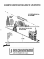
Slopes are a major factor related to loss-of-control and tipover
accidents, which can result in severe injury or death,, All slopes
require extra caution, if you cannot back up the slope or if you feel
uneasy on it, do not mow it,
•
DO:
•
Mow up and down slopes, not across+
Remove obstacles such as rocks, tree limbs, etc..
•
•
•
Watch for holes, ruts, or bumps
Uneven terrain could
overturn the machine, Taft grass can hide obstacles.
Use slow speed. Choose a low gear so that you will not have
to stop or shift while on the slope
Follow the manufacturer's
recommendations
for wheel
weights or counterweights to improve stabifity+
Use extra care with grass catchers or other attachments
These can change the stability of the machine,
•
•
Keep aElmovement on the slopes sfowand gradual Do not
make sudden changes in speed or direction.
Avoid starting or stopping on a slope,, If tires lose traction,
disengage the blades and proceed slowly straight down the
slope,
•
•
•
•
Keep nuts and bolts, especially blade attachment bolts, light
and keep equipment in good condition,,
Never tamper with safety devices,
Check their proper
operation regularly
Keep machine free of grass, leaves, or other debris build-up+
Clean oil or fuel spillage
Allow machine to cool before
storing.
Stop and inspect the equipment if you strike an object.
Repair, if necessary, before restarting,
Never make adjustments or repairs with the engine running.
Grass catcher components are subject to wear, damage, and
deterioration, which could expose moving parts or allow
objects to be thrown, Frequently check components and
replace with manufacturer's recommended parts, when necessary,
Mower biades are sharp and can cut+ Wrap the blade(s) or
wear gloves, and use extra caution when servicing them,,
Check brake operation frequently. Adjust and service as
required.
tant safety
precautions.
It means
Look
for this symbol
point out imporCAUTION!!!
BECOMEto ALERT!!!
YOUR
SAFETY IS INVOLVED.
DO NOT:
•
Keep children out of the mowing area and under the watchful
care of another responsible adult.
Be alert and turn machine off if children enter the area.
•
Mow only in daylight or good artificial lighL
Do not operaie the machine while under the influence of
alcohol or drugs..
Watch for traffic when operating near or crossing roadways.+
Usa extra care when loading or unloading the machine into
a trailer or truck
SLOPE
CHILDREN
Do not turn on slopes unless necessary, and then, turn slowly
and gradually downhill, if possible
Do not mow near drop-offs, ditches, or embankments, The
mower could suddenly turn over if a wheel is over the edge
of a cliff or ditch, or if an edge caves in
Do not mow on wet grass, Reduced traction could cause
sliding.
Do not try to stabilize the machine by putting your foot on the
ground°
Do not use grass catcher on steep slopes,
CAUTION:
Always disconnect spark
plug wire and place wire where it cannot
contact spark plug In order to prevent
accidental
starting when setting up,
transporting,
adjusting
or making
repairs.
2
=RODUCT
CONGRATULATIONS
on your purchase of a Sears
tractor, tt has been designed, engineered and manufactured to give you the best possible dependability and
performance,
Should you experience any problem you cannot easily
remedy, please contact )/our nearest Sears Service
Center/DepartmenL
We nave competent, well-trained
technicians and the proper tools to service or repair this
tractor.
Please read and retain this manual The instructions will
enable you to assemble and maintain your tractor propefly, Always observe the "SAFETY RLJLES"_
MODEL
NUMBER
917255561
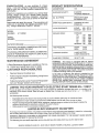
SPECIFICATIONS
HORSEPOWER:
12.0
GASOLINE CAPACITY:
5 QUARTS
UNLEADED REGULAR
OIL (3.0 PINTS):
SAE 30 (Above 32°F)
5W-30(Below 32°F)
SPARK PLUG (GAP_030IN.):
CHAMPION RJ-19LM
STD361458
VALVE CLEARANCE:
INTAKE
.005 - °007 IN o
EXHAUST 009 _ o011IN
GROUND SPEED:
FORWARD
1st
2nd
3rd
4th
5th
REVERSE:
1.1(_
2.00
3.00
4.20
500
1.50
TIRE PRESSURE:
FRONT:
REAR:
14 PSI
10 PSt
CHARGING SYSTEM:
3 AMPS BATTERY
5 AMPS HEADLIGHTS
BLADE BOLT TORQUE:
30-35 FT, LBS,
SERIAL
NUMBER
DATE OF PURCHAS E
THE MODELAND SERIAL NUMBERS WILL BE FOUND
ON A PLATE UNDER THE SEAT.
YOU SHOULD RECORD BOTH SERIAL NUMBER AND
DATE OF PURCHASE AND KEEP IN A SAFE PLACE
FOR FUTURE REFERENCE,
MAINTENANCE
AGREEMENT
WARNING:
This tractor is equipped with an internal
combustion engine and should not be used on or near any
un mproved forest-covered, brush-covered or grass-covered land unless the engine's exhaust system is equipped
with a spark attester meeting applicable local or state taws
(if any). If a spark arrester is used, it should be maintained
in effective working order by the operator.
In the state of California the above is required by law
(Section 4442 of the California Public Resources Code).
Other states may have similar laws, Federal laws apply on
federal lands, A spark arrester for the muffler is available
through your nearest Sears Authorized Service Center
(See the REPAIR PARTS section of this manual)
A Sears Maintenance Agreement is available on this tractor. Contact your nearest Sears store for details.
CUSTOMER
RESPONSIBILITIES
*
Read and observe the safety rules.
o
Follow a regular schedule in maintaining, caring for and
using your tractor°
,
Follow the instructions under "Customer Responsibilities" and "Storage" sections of this manual.
,
iiiinll
,i
i
n ,11,1,1111
LIMITED TWO YEAR WARRANTY
MPH
MPH
MPH
MPH
MPH
MPH
iHll
ON ELECTRIC
u,iH,
i IlllHHHI
START RIDING EQj;?MENT
For two (2) years from the date of purchase, if this riding equipment is maintained, lubricated and tuned uo according to the
instructions in the owner's manual, Sears will repair or replace, free of charge, any parts found to be d,-_e:';',_ in material or
workmanship.
This Warranty does not cover:
,
•
•
o
Expendable items which become worn during normal use, such as blades, spark plugs, air cteaners and belts
Tire replacement or repair caused by punctures from outside objects, such as nails, thorns, stumps, or glass.
Repairs necessary because of operator abuse, negligence, improper storage or accident or the failure to maintain the
equipment according to the instructions contained in the owner's manual.
Riding equipment used for commercial or rental purposes
LIMITED 90 DAY WARRANTY
ON BATTERY
For 90 days from date of purchase, if any battery inciuded with this riding equipment proves defective in material or workmanship
and our testing determines the battery will not hold a charge, Sears will replace the battery at no charge
WARRANTY SERVICE IS AVAILABLE BY RETURNING THE RIDING EQUIPMENT TO THE NEAREST SEARS SERVICE
CENTER/DEPARTMENT IN THE UNITED STATES.
This Warranty gives you specific legal rights, and you may also have other rights which may vary from state to state
SEARS, ROEBUCK AND CQ, D/731CR-W, SEARS TOWER, CHICAGO, ILLINOIS 60684
IH
3
N,,
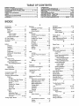
TABLE OF CONTENTS
SAFETY RULES ............................................................
2
PRODUCT SPECIFICATIONS ....................................... 3
CUSTOMER RESPONSIBILITIES
..................... 3, 14-17
WARRANTY ...................................................................
3
TABLE OF CONTENTS .................................................
4
INDEX .............................................................................
4
TRACTOR ACCESSORIES ........................................... 5
ASSEMBLY ................................................................
7"9
OPERATION ...........................................................
10-t3
MAINTENANCE SCH EDULE ...................................... 14
SERVICE AND ADJUSTMENTS ............................ 18-23
STORAGE ....................................................................
24
TROUBLESHOOTING
............................................
25-26
REPAIR PARTS - TRACTOR ................................. 28.43
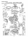
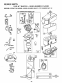
REPAIR PARTS - ENGINE ..................................... 44-48
PARTS ORDERING/SERVICE ................... BACK _GE
INDEX
A
Accessories ........................................................
5
Adjustments:
Brake ............................................. 20
Carburetor ....................................... 23
Mower
Front-To-Back ............................19
Side-To-Side ................................19
Throttle Control Cabie .......................
23
Air Filter, Engine .................................. 17
Air Screen, Engine
17
Assembly ..........................................................
7-9
B
................
..................
Battery:
Charging ..................................................
8
Cleaning ..............................................
16
Installation ............................................9
Levels .............................................8,16
Preparation ..........................................8
Starting with Weak Battery ........... 21
Storage .................................................
24
Terminals ........................................ 16
Belt:
Motion Drive
Removal/Replacement
........... 20
Mower Blade Drive
RemovaVReplacement ...............
20
Blade:
Sharpening ...........................................
15
Replacement ......................................15
Brake Adjustment ................................... 20
C
Carburetor Adjustment ...........................24
Controls, Tractor ......................................10
Customer Responsibilities .................
14-17
Engine:
Air Filter ..................................... 17
Air Filter Foam Pre-Oleaner .... 17
Air Screen, Engine .................... 17
Battery ......................................... 16
Cooling Fins, Engine ...................I7
Engine Oil .................................... t6
Fuel Filter .................................... 17
Spark Plugs
17
Tractor:
Blade ...............................................15
Lubrication Chart ..................... 14
Maintenance Schedule ............ 14
Tire Care ..............................8,15,21
E
Electrical:
interlocks and Relays .....................22
Schematic ...................................... 27
Wiring Diagram .....................................
28
Engine:
Air Filter ............................................ t 7
Air Filter Foam Pre-Oleaner ..........17
Air Screen ...............................................
17
Cooling Fins, Engine ...........................
17
Oil Change ........................................!6
Oil Level .............................................
12,16
Oil Type .................................................
16
Preparation ........................................12
Repair Parts ..........................................
44-48
Starting ..................................................
13
Storage ................................................
24
F
Filter:
Air Filter
Air Filter Foam Pre-Cleaner ...........17
Fuel .........................................................
17
Fuel:
Type ...................................................12
Storage ....................................................
24
Fuse ..............................................................
22
...............................................
7
H
Headlights ............................................... 22
Hood Removal/Installation .................... 22
L
Leveling Mower Deck .............................19
Lubrication:
Chart
14
...........................................
........
M
Maintenance
Mower:
Schedule .......................... 14
Adjustment, Front-to-Back .............19
Adjustment, Side-to-Side ............ ! 9
Blade Sharpening .............. :.......... 15
Blade Replacement ........................15
Cutting Height
11
Installation ...................................... 18
.............
......................
Operation ......................................... 12
Removal ........................................... 18
...................................
Cutting Height, Mower .......................... ll
1
Mowing Tips ........................................... t 3
Muffler ...................................................... t 7
Spark Arrester .................................
3,38
O
Oil:
Cold Weather Conditions ..... 12,16
Engine ........................................... 16
Storage ........................................... 24
4
Operation ................................................
10-13
Operating Mower
12
Options:
Accessories ...........................................
5
.....................................
Spark Arrestel: ..............................3,38
P
Parking Brake .........................................
10-t 1
Parts Bag ................................................. 6
Parts, ReplacemenlJRepair ............ 28-43
Product Specifications ...................................
3
R
Repair Parts ........................................28-43
S
Safety Rules .....................................................
2
Seat
Service and Adjustments ................ 18-23
Carburetor ....................................
_.......23
Fuse ......................................................
22
Hood Removal/Installation
.......... 22
Motion Drive Belt
Removal/Replacement
...............
20
Mower Blade Drive Belt
....................
...........................................
8
Removal/Replacement
........... 20
Mower Adjustment
Front- to-Back ......................... 19
Side-to-Side .............................. 19
Mower Installation .......................... 18
Mower Removal .............................. 18
Tire C_ire ...................................8,15,21
Slope Guide Sheet ..................................51
Spark Plugs ............................................ 17
Specifications .......... :..................................
3
Starting the Engine .......................... 12-13
Steering Wheel .........................................
7,21
Stopping the Tractor ...................................
11
Storage ................................................... 24
T
Throttle Control Cable
Adjustment ..........................................
23
Tires ...............................................................
8,15,21
Trouble Shooting Chart .....................25-26
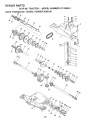
Transaxle:
Repair Parts .............................
42-43
W
Warranty .................................................... 3
Wiring Diagram ...................................... 28
Wiring Schematic ................................... 27
ACCE$$ORUSS AND ATTACH
i
........
, ,, ,i,,,i,,,i
ENT$
i ii ii1,1,
,,,
i
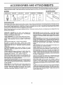
Those accessories and attachments were available when the tractor was purchased. They are also available at most Soars retail outlets,
catalog and service centers. Most Sears stores can order these ffems for you when you provide the model number of your tractor.
ENGINE
SPARK PLUG
MAINTENANCE
MUFFLER
AIR FILTER
GAS CAN
ENGINE OIL
STABILIZER
BLADES
BELTS
PERFORMANCE
Sears offers a wide variety of attachments that fit your tractor. Many of these are listed below with brief explanations of how they can help
you° This list was current at the time of publication; however, it may change in future years - more attachments may be added, changes
may be made in these attachments, or some may no longer be available or fit your model Contact your nearest Sears store for the
accessories and attachments that are available for your tractor.
Most of these attachments
attaching and detaching°
do not require additional hitches or conversion kits (those that do are indicated) and are designed for easy
PERMANEX
BAGGER lets you collect grass clippings and
leaves for a healthier, neater looking lawn. Two Permanex
containers hold 30-gallon plastic bags°
LAWN SWEEPERS let you collect grass clippings and leaves.
LAWN VACS for powerful collection of heavy grass clippings and
leaves° Wand attachment to pick up debris in hard-to-reach
places°
CARTS make hauling easy_ Variety of sizes avaifable.
ROLLER for smoother lawn surface.
36-inch wide, 18-inch
diameterwater-tightdrum
hoIdsupto390Ibs_ofwefght.
Rounded
edges prevent harm to turf° Adjustable scraper automatical{y
cleans drum°
SPREADER/SEEDERS
make seeding, fertilizing, and weed
killing easy_ Broadcast spreaders are a_so useful for granular
cre.icers and sand,
CORING AERATOR takes sma{l plugs out of soil to allow moisture and nutrients to reach grass roots_ 36-inch swath. 24
hardened steel coring ttps_ t50 Ib, capacity weight tray.
AERATOR promotes deep root growth for a healthy lawn. Tapered 2.5-inch steel spikes mounted on 10-inch diameter discs
puncture holes in soil at close Intervals to let moisture soak in
Steel weight tray for increased penetration_
MULCH RAKE/DETHATCHER
loosens soii and flips thatch and
matted leaves to lawn surface for easy pickup. Twenty spring tine
teeth. Usefultopreparebareareasfarseeding
AvaiIablefor front
or rear mounting
SPRAYERS use 12-volt DC electric motor that connects to the
tractor battery er other 12-voft source.
Includes booms for
automatic spraying when pulling, and hand held wand for spot
spraying.
Wand has adjustable spray pattern. For applying
herbicides, insecticides, fungicides, and Iiquid fertilizers.
SNOW BLADE for snow removal only. 14-Inch high, 42_Inch
wide blade clears 38-1nch path when angled left or right. Raises,
towers with side leven Adjustable skids; replaceable, reversible
scraper bar. (Use with tire chains, wheel weights, er rear drawbar
weight,)
SNOWTHROWER has 40-Inch swath. Drum-type auger handtes
powdery and wet!heavy snow_ Mounts easily with simple pin
arrangemenL Discharge chute adjusts from tractor seat, 6-inch
diameter spout discharges snow 10 to 50 feet. Lift controlled at
tractor seat. (Use with chains, wheel weights, or rear drawbar
weighL)
TIRE CHAINS are heavy duty; closely spaced extra-large cross
links give smooth ride, outstanding traction.
WHEEL WEIGHTS for rear wheeIs provide needed traction for
snow removat or dozing heavy materials. In pairs° (30 lbs. each.)
TRACTOR CAB has heavy duty vinyl fabric over tubular steel
frame, ABS plastic top; clear plastic windshield offers 360 degree
visibility. Hinged metal doors with catch. Keeps operator warm
and dry_ Remove vinyl and windshields for use as sun protector
in summer. (Catalog only,)
Optional accessories
for tractor cab: tinted/tempered solid
safety glass windshield with hand operated wiper; 12-volt amber
caution light for mounting on cab top. (Catalog only.)
TRACTOR COVER protects tractor from weather.
Made of
Evolution 3 fabric (water-repellent, extremely breathable, light
weight, soft, non-abrasive, pliable in all temperatures, durable,
stain/tear/puncture resistant, will not shrink or stretch.) (Catalog
onty.)
TILLER has 5 hp engine and 36-inch swath to prepare seed beds,
cultivate, and compost garden residue. Tiller has its own built-in
lift and depth control system and does NOT require a sleeve hitch.
Fits any lawn, yard, or garden tractor. Slmply hook up to the
tractor drawbar and go!
....................
. .............. ,_,,,., .......
, ,.
,,
,, ,,
,..-
; ......
, ,,,,,,_
,,,,_
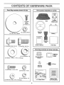
CONTENTS OF HARDWARE PACK
Parts Bag contents
.........
,,i,,,, i
shown full size
,,,
1,1,,,,,i...........
Parts pa ked
.
,,,
,,,,
eparately
in carton
,...........
O
Seat
Sheet
©
Battery acid
112
Steering
Wheel
Battery
Steering
Boot
t
i
(1) Shoulder Bolt 5/16-18
@
(1) Washer
Owner's
(!) Hex Bolt 1/2-13 x 1
,
,,
Manual
,,,
,
Parts bag contents not shown full size
'
(t) Lock Washer
....
_[_
Steering Wheel
Adapter
1/2
17/32 x '1-3/16x I2 Gauge
@
(2) Hex Boits 1/4-20 x 3/4
!_l
Wheel
Steering
Insert
_(2)
Keys
Steering
Bushing
'_
(2) Hex Nuts 114-20
G
(2) Lock Washers
(2) Washers
Parts Bag
,..............
........
.j'
E
€
I
I
1/4
15 ° Slope Sheet
9/32 x 5/8 x 16 Gauge
6
Battery Caps
and Instructions
i
. ii,.i,
i
u ,,,
i i
n lUll,i,
ASSEM
L
I
IIU
i
I
!1
....
i1,,
I
,
IIII
III
IIIII
nl,,ll
LY
,
IIIII
Your new tractor has been assembled at the factory with except on of those parts left unassembled for shippfng purposes.
To ensure safe and proper operation of your tractor all parts and hardware you assemble must be tightened securely. Use
the correct tools as necessary to insure their proper tightness.
TOOLS
REQUIRED
INSERT
FOR ASSEMBLY
A socket wrench set will make assembly easier+ Standard
wrench sizes are listed,
(l)
"X._
3/4" wrench
5/16" wrench
(1) 1/2" wrench
Tire pressure gauge
Screwdriver
(l)
Utility knife
(2) 7/16" wrenches
9/t6" wrench
_2-114"
STEERING
WHEEL
ADAPTER,,_,_
TO REMOVE TRACTOR FROM CARTON
•
DtA. WASHER
jSTEERING
When right and left hand is mentioned in this manual, it
means when you are in the operating position (seated
behind the steering wheel).
UNPACK
3t8- 24 HEX LOCKNUT
_
STEERING
BUSHING
CARTON
Remove all accessible loose parts and parts cartons
from carton (See page 6)°
•
Cut along lines on carton, from top to bottom, all four
corners of carton and lay panels flaL
•
Check for any additional
remove.
STEERING _i
BOOT
i
TAB
STEERING
(ASSEMBLY
POSITION)
loose parts or cartons and
":'?
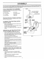
BEFORE ROLLING TRACTOR OFF SKID
ATTACH
STEERING
WHEEL
(See Fig, 1)
+
Slide the steering bushing over the steering shaft,
°
Raise steering shaft forward until screw holes in dash
line up with steering bushing. Install two (2) sheet
metal screws and tighten securely,
,
Position steering boot over steering shall
•
Place tabs of steering boot over slots in dash and push
down to secure°
•
Slide steering wheel adapter onto upper steering shaft,
•
Position front wheels of the tractor so they are pointing
straight forward.
•
Position steering wheel so cross bars are horizontal
(]eft to right) and slide onto adapter.
•
Assemble large flat washer and 3/8-24 hextocknut and
tighten securely,
•
Snap insert into center of steering wheel.
FIG. 1
•
Remove protective plastic from tractor hood and grill,,
IMPORTANT:
CHECK
FOR AND REMOVE
ANY
STAPLES tN SKID THAT MAY PUNCTURE TIRES WHERE
TRACTOR IS TO ROLL OFF SKID.
(See Ftg. 6)
•
Raise attachment lift lever to its highest position.
•
Release parking brake by depressing
pedal.
•
•
Place gearshift lever in "NEUTRAL" position.
Roll tractor backwards off skid.
,
Remove banding holding discharge guard up against
tractor.
clutch/brake
7
WHEEL
ASSE
BLY
HOW TO SET UP YOUR TRACTOR
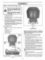
INSTALL
PREPARE
Adjust seat before tightening adjustment bolt.
°
Remove cardboard packing on seat pan.
BATTERY
i llll i,.
(See Fig. 2)
, i ,, i ,m i ,t=_,,,,
CAUTION: Wear eye and face shield,
SEAT (See Fig. 3)
Place seat on pan and assemble shoulder bolt.
Wash hands or clothing Immediately if
accldentallyln
contact with battery actd.
Do not smoke. Fumes from charged
battery acld are explosive.
Read the Instructions
Included with the
battery vent caps. Alwayswear gloves,
clothing and goggles to protect your
hands, skin and eyes.
.
Assemble adjustment bolt, lock washer and flat washer
loosely. Do not tighten.
•
Tighten shoulder bolt securely.
,
Lower seat into operating position and sit on seat.
.
SIide seat until a comfortable position is reached which
aIIows you to press clutch/brake pedal all the way down
(See Fig. 6).
•
Get off seat without moving its adjusted position.
,
Raise seat and tighten adjustment bolt securely.
Your tractor has a battery charging system which is sufficient for normal use. However, periodic charging of the
battery with an automotive charger wili extend its life.
"
See instructions packed with vent caps in parts bag.
,
Fill battery with acid. Fill each cell until it reaches the
bottom of the vent we{Is. Do not overfill.
•
Ailow battery to stand and settle for at least thirty
minutes. After standing, check the _evel of acid.
If
below the vent wells, add more acid until the correct
level is reached.
SEAT PAN
SHOULDER
BOLT
While battery is standing (after adding acid) and later, while
battery isbeing charged, continue with assembly of tractor.
IMPORTANT:
TO MAXiMiZE THE LIFE OF YOUR
BATTERY, IT IS NECESSARY THAT THE BATTERY BE
CHARGED BEFORE USE FAILURE TO CHARGE
BATTERY CAN RESULT {N A SHORTENED BATTERY
LiFE
•
oFLAT WASHER
ADJUSTMENT
BOLT
Charge battery at a rate of 6 amperes for 1 hour. Use
a 12 volt battery charger. Observe all safety precautions
required for battery charging.
.
FIG, 3
CHECK
Check the acid level after the battery is charged, If the
acid has fallen below the correct level, add distilled or
iron free water.
.
Check battery case for leakage to make sure that no
damage has occurred in handling.
•
Dispose of excess battery acid, Neutralize acid for
disposal by adding it to four inches of water in a five
gallon plastic container. Stir with a wooden or plastic
paddle white adding baking soda until the addition of
more soda causes no more foaming,
o
Follow instructions on how to install battery.
CUTAWAYVIEW
j
j
_
t _
.
r_ _ r.,'J
F1Go2
r_/f_t
PRESSURE
Reduce tire pressure PSI shown in "PRODUCT
SPECIFICATION on page 3 of this manual.
CHECK
DECK
LEVELNESS
For best cutting results, mower housing should be properly
leveled.
See "TO LEVEL MOWER HOUSING" in the
Service and Adjustments section of this manual.
CHECK
BELTS
VENTCAP
w. W LL
BATTERY
r-_ _ _
TIRE
The tires on your tractor were overinflated at the factory for
shipping purposes. Correct tire pressure is important for
best cutting performance.
Install the vent caps to cover the vent weIIs. Wash the
top of the battery with water to remove any acid, then
wipe dry,
•
" LOCK WASHER
FOR
PROPER
POSITION
OF ALL
See the figures that are shown for replacing motion and
mower blade drive belts in the Service and Adjustments
section of this manual. Verify that the belts are routed
correctly.
CHECK BRAKE SYSTEM
CELLAClD
8
After you learn how to operate your tractor, check to see
that the brake is properly adjusted. See "TO ADJUST
BRAKE" in the Service and Adjustments section of this
manual
ASSEMBLY
iNSTALL
BA3"TEF Y (See Figs. 4 & 5)
CAUTION:
Do not short battery termi-
metal bracelets,
wristwatch
bands,
nals. Before
installing battery, remove
rings,
etc,
Positive terminal must be connected
first to prevent sparking from accidental grounding.
o
Lift seat to raised position.
•
Open battery box dOOrr
°
Lower battery into battery box with battery terminals
toward front of tractor_
=
Be sure battery drain tube is attached to battery box..
•
First connect RED battery cable to positive (+) battery
terminal with hex bott, flat washer, lock washer and hex
nut as shown. Tighten securely
o
Connect BLACK grounding cable to negative (-) battery terminal with remaining hex bolt, flat washer, lock
washer and hex nut. Tighten securely.
•
Close battery box door_
VENTCAPS
Open battery box door for:
=
Inspection for secure connections
(to tighten hard-
ware).
o
Inspection for corrosion.
•
Testing battery.
o
Jumping (if required).
o
Periodic charging°
BEFORE YOU OPERATE AND ENJOY YOUR NEW
TRACTOR, WE WISH TO ASSURE THAT YOU RECEIVE
THE BES T PERFORMANCE AND SA TISFA C TION FROM
THIS QUALITY PRODUCT.
BATTERY
BOX DOOR
PLEASE REVIEW THE FOLL 0 WING CHECKLIST:
v"
All assembly instructions have been completed.
v" No remaining loose parts in carton_
POSITIVE
(RED)
CABLE
NEGATIVE
¢"
Battery is properly prepared and charged_
1 hour at 6 amps)_
(Minimum
v"
Seat is adjusted comfortably and tightened securely
v" All tires are properly inflated. (For shipping purposes,
the tires were over-inflated at the factory).
v"
CABLE
Be sure mower deck is properly leveled side-to-side/
front-to-rear for best cutting results.. (Tires must be
properly inflated for leveting).
v" Check mower and drive belts. Be surethey are routed
properly around pulleys and inside all belt keepers.
•/
LOCK WASHER
HEX
BOLT
WHILE LEARNING HOW TO USE YOUR TRACTOR, PAY
EXTRA A TTENTION TO THE FOLLOWING IMPORTANT
ITEMS:
#"
POSITIVE (+) TERMINAL
NEGATIVE
FIG. 4
TERMINAL
Check wiring.. See that all connections are still secure
and wires are properly clamped.
Engine oil is at proper level,
V" Fuel tank is filled with fresh, clean, regular unleaded
gasoline.
J" Become familiar with all controls - their' location and
function° Operate them before you start the engine..
_"
Be sure brake system is in safe operating condition.
i
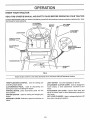
OPERATION
KNOW YOUR TRACTOR
READ
THIS
OWNER'S
MANUAL
AND
SAFETY
RULES
BEFORE
OPERATING
YOUR
TRACTOR
Compare the illustrations with your tractor to familiarize yourself with the locations ofvarious controls and adjustments,
this manual for future reference,
ATTACHMENT
CLUTCH LEVER
IGNITION
SWtTCH
Save
LIFT LEVER
PLUNGER
ATTACHMENT
LIFT LEVER
LIGHT SWITCH
-.\
THROTTLE/CHOKE
CONTROL
CLUTCH/BRAKE
MOWER DECK
HEIGHT ADJUSTMENT
POSITIONS
[
t
PARKING
GEARSHIFT
LEVER
FIG. 6
Sears tractors conform to the safety standards of the American National Standards Institute°
LIGHT SWITCH:
THROTTLE/CHOKE
CONTROL: Used for starting and
controlling engine speed.
CLUTCH/BRAKE
PEDAL:
Used for declutching and
braking the tractor and starting the engine.
PARKING BRAKE: Locks clutch/brake pedal into the
brake position.
IGNITION SWITCH: Used for starting and stopping the
engine_
GEARSHIFT LEVER: Selects the speed and direction of
tractor.
Turns the headlights on and off.
ATTACHMENT CLUTCH LEVER: Used to engage the
mower blades, or other attachments mounted to your
tractor_
ATTACHMENT LIFT LEVER: Used to raise, lower, and
adjust the mower deck or other attachments mounted to
your tractor_
LIFT LEVER PLUNGER: Used to release attachment lift
lever when changing its position.
10
...................
...............................
,................ '
v,,
i
......
_r
OPERATION
The operation of any tractor can result in foreign objects thrown into the eyes which can
result in severe eye damage. Always wear safety glasses or eye shields while operating
your tractor or performing any adjustments or repairs. We recommend wide vision safety
mask for over the spectacles or standard safety glasses, available at Sears Retail or
Catalog stores°
HOW TO USE YOUR TRACTOR
TO SET PARKING
BRAKE
(See Fig. 7)
o
Depress clutch/brake pedal into full "BRAKE" position
and hold_
=
Place parking brake lever in "ENGAG ED"position and
release pressure from clutclVbrakepedal. Pedalshould
remain in "BRAKE" position, Make sure parking brake
will hold tractor secure.
IGNITION
KEY _
NOTE: Under certain conditions when tractor is standing
idle with the engine running, hot engine exhaust gases may
cause "browning" of grass. To eliminate this possibility,
always stop engine when stopping tractor on grass areas°
,
ATTACHMENT
CLUTCH LEVER
"ENGAGED"
POSITION
"DISENGAGED"
\
PARKING BRAKE
"DISENGAGED"
POSITION
MOWER BLADES Move attachment clutch lever to "DISENGAGED" position,
Depress clutch/brake pedal into full "BRAKE" position.
lever to "NEUTRAL" position_
NOTE: Failure to move throttle control to "SLOW" position
and allowing engine to idle before stopping may cause
engine to "backfire",
Turn ignition key to "OFF" position and remove key.
Always remove key when leaving tractor to prevent
unauthorized use.
o
Never use choke to stop engine.
(See
•
Start tractor with clutch/brake pedal depressed
gearshift lever in "NEUTRAL" position°
°
Move gearshift lever to desired
and
position,
MOWER
CU'I-[ING HEIGHT
(See
lift lever determines
the
•
Grasp lift lever,
°
Press plunger with thumb and move lever to desired
position.,
°
The average lawn should be cut to approximately
2-1/2 inches during the cool season and over 3 inches
during hot months. For healthier and better looking
lawns, mow often and after moderate growth_
°
For best cutting performance, grass over 6 inches in
height should be mowed twice, Make the first cut
relatively high; the second to desired height.
Move throttle control to "SLOW" position.
o
AND BACKWARD
The cutting height range is approximately 1-112 to 4'L The
heights are measured from the ground to tne b_ade tip with
the engine not running° These heights are approximate
and may vary depending upon sob conditions, height of
grass and types of grass being mowed.
GROUND DRIVE -
o
Full throttle offers the best bagging and mower performance.
The position of the attachment
cutting height,
STOPPDNG (See Fig. 7)
o
Move gearshift
ENGINE -
o
TO ADJUST
Fig.6)
FIG. 7
o
Operating engine at less than full throttle reduces the
battery charging rate.
o Slowly release clutch/brake pedal to start movemenL
IMPORTANT: BRING TRACTOR TO A COMPLETE STOP
BEFORE SHIFTING OR CHANGING GEARS. FAILURE
TO DO SO WILL SHORTEN THE USEFUL LIFE OF YOUR
TRANSAXLE.
POSITION
.
(See Fig. 7)
The direction and speed of movement is controlled by the
gearshift lever
GEARSHIFT
LEVER
POSITION
CONTROL
o
TO MOVE FORWARD
Fig. 6)
PARKING
BRAKE
"ENGAGED"
/
_........
Always operate engine at full throttle.
"BRAKE"
CLUTCH/BRAKE
PEDAL "DRIVE"
grass catcher, etc.
TO USE THROTTLE
POSITION
THRO'rrL_
CHOKE
CONTROL"
LEVER
pletely, as described above, before leavCAUTION:
Always position;
stop tractor
coming
the operator's
to empty
(_
11
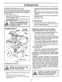
OPERATUON
TO OPERATE
MOWER
(See Fig. 8)
°
Your tractor is equipped with an operator presence sensing
switch. Any attempt by the operator to leave the seat with
the engine running and the attachment clutch engaged will
shut off the engine.
°
•
Select desired height of cut.
•
Engage mower by slowly moving attachment cTutch
lever to ' ENGAGED position.
TO STOP MOWER - Move attachment clutch lever to
"DISENGAGED" position.
•
.
Make all turns slowly.
TO TRANSPORT
LEVER
"ENGAGED"
POSITION
Move gearshift lever to 1st gear and be sure you have
afiowed room for tractor to roil slightly as you restart
movement,
To restart movement, slowly release parking brake and
clutch/brake pedal.
CAUTION: Do not operate the mower
without either the entire grass catcher,
on mowers so equipped, or the discharge guard in place°
ATTACHMENT CLUTCH
"DISENGAGED"POSITION
If stepping is absolutely necessary, push clutch/brake
pedal quickly to brake position and engage parking
brake.
.
Raise attachment lift control to highest position.
°
When pushing or towing your tractor, be sure gearshift
lever is in "NEUTRAL" position.
.
Do not push or tow tractor at more than five (5) MPH,
BEFORE
ATTACHMENT
LIFT LEVER
HIGH POSITION
CHECK
STARTING
ENGINE
THE ENGINE
OIL LEVEL
(See Fig. 13)
The engine in your tractor has been shipped from the
factory already filled with summer weight oil,,
LOW
POSITION
•
Check engine oil with tractor on level ground,
-
Remove oil fill dipstick and wipe clean, replace and
screw cap tight, wait for a few seconds, remove and
read oil level, If necessary, add oil until "FULL" mark
on dipstick is reached, Do not overfill.
°
For cold weather operation you should change oil for
easier starting (see "OIL VISCOSITY CHART" in the
Customer Responsibilities section of this manual).
°
To change engine oil, see the Customer Responsibilities section in this manual
ADD GASOLINE
°
Fill fuel tank. Use fresh, clean, regular unleaded
gasoline. (Use of leaded gasolinewill increase carbon
and lead oxide deposits and reduce valve life).
IMPORTANT:
WHEN OPERATING IN TEMPERATURES
BELOW 32°F(0°C), USE FRESH, CLEAN WINTER GRADE
GASOLINE TO HELP INSURE GOOD COLD WEATHER
STARTING.
g.H_
RUNNER
DISCHARGE
WARNING:
Experience indicates that alcohol blended
fuels (catled gasohol or using ethanol or methanol) can
attract moisture which leads to separation and formation of
acids during storage. Acidic gas can damage the fuel
system of an engine while in storage. To avoid engine
problems, the fuel system should be emptied before storage of 30 days or longer, Drain the gas tank, start the
engine and let it run until the fuel lines and carburetor are
empty. Use fresh fuel next season_ See Storage instructions for additional information. Never use engine or
carburetor cleaner products in the fuel tank or permanent
damage may occurA
GUARD
FIG. 8
TO OPERATE
i
ON HILLS
, ,i,,
,,i...............
hills with elopes greater than !5 ° and
CAUTION:
Do not drive up or down
do not drive across any' slope.
II
I
°
Choose the slowest speed before starting up or down
hills.
.
Avoid stopping or changing speed on hills.
•
if slowing is necessary, move throttle control lever to
slower position
i_
filler neck. Do not overfill. Wipe off any
spilled oil or fuel Do not store, spill or
,gas
i iirl
use
AUTION:
gasoline Fill
near
to an
bottom
open of
flame.
tank
=
12
........
i
m,i
..........................................
i
i
iiii
i,
......................
,I"JlJJlllLL
I I,II,IllL
OPERATIO
TO START
ENGINE
(See Fig. 7)
When starting engine for the first time or if engine has
run out of fuel, it wilt take extra cranking time to move
fuel from the tank to the engine_
•
•
Depress the clutch/brake pedal and set the parking
brake°
Place gearshift lever in "NEUTRAL" position°
.
Move attachment clutch to "DISENGAGED"
•
Move throttle control lever to "CHOKE" position for
cold engine start.
For warm engine start, move
throttle control to "FAST" position,
•
•
Drive so that clippings are discharged onto the area
that has been cut. Have the cut area to the right of
the tractor, This will result in a more even distribulion of clippings and more uniform cutting.
.
When mowing large areas, start by turning to the
right so that clippings will discharge away from
shrubs, fences, driveways, etc. After one or two
rounds, mow in the opposite direction making left
hand turns until finished (See Fig° 9).
•
If grass is extremely tall, it should be mowed twice
to reduce load and possible fire hazard from dried
clippings. Make first cut relatively high; the second
to the desired height.
•
Do not mow grass when it is wet,
plug mower and leave undesirable
grass to dry before mowing_
•
Always operate engine at full throttle when mewing
to assure better mowing performance and proper
discharge ef material.
Regulate ground speed by
selecting a low enough gear to give the mower
cutting performance as well as the quality of cut
desired.
•
When operating attachments, select a ground speed
that wilt suit the terrain and give best performance of
the attachment being used.
position,
•
Turn ignition key clockwise to "START" position and
release key as soon as engine starts. Do not run
starter continuously for more than fifteen seconds
per minute, If engine does not start after several
attempts, move throttle control to "FAST" position,
wait a few minutes and try again,
When engine starts, move throttle control to desired
•
position,
Allow engine to warm up for a few minutes before
engaging drive or attachment clutch.
NOTE: If at a high altitude (above 3000 feet) or in cold
temperatures (below 32 ° F), the carburetor fuel mixture
may need to be adjusted for best engine performance.
See "TO ADJUST CARBURETOR'
in the Service and
Adjustments section of this manual,
MOWING TiPS
°
Tire chains cannot be used when the mower housIng is attached to tractor,
•
Mower should be properly leveled for best mowing
performance. See "TO LEVEL MOWER HOUSING"
in the Service and Adjustments
section of this
manual,
.
Use the runner on the right hand side of mower as
a guide.
The blade cuts approximately
an inch
outside the runner (See Fig, 8).
The left hand side of mower should be used for trimming,
•
i.,
FIG, 9
13
....
Wet grass will
clumps,. Allow
CUSTOMSR
,
LtT ES
RESPONS
i
MAINTENANCE
....
=
i , = n .............
SCHEDULE
FiLL IN DATES
AS YOU COMPLETE
REGULAR SERVICE
SERVICE
DATES
Check Brake Operation
Check Tire Pressure
6_
T
Check for Loose Fasteners
64#
R
Sharpen/Replace Mower Blades
T
Check Battery Level/Recharge
0
a
Clean Battery and Terminals
CheckTransmisston Cooling
;
J
;
_
.
= ....
Lubrication Chart
Adjust BIade Belt(s) Tension
J
.............
'
Adjust Motion Ddve Belt(s) Tension
Check Engine _Oil
Level
Change Engine Oil
E
G
Clean Air Filter
CleanAir Screen ..............
inspectMuffler/Spark Arrestor
I
Replace Oit Filter (If equipped)
N
e"
v'2
e"
Clean Engine Cooling Fins
Replace Spark Plug
Replace Air Filter Paper Cartridge
Replace Fuel Filter
1 - Change more often when operating under e heavy load or in high ambient temperatures
2 - Service more often when operating In dirty or dusty conditions
GENERAL
3 - If equipped
with oil filter, change oil every 50 hours
4 - Replace blades more often when mewing In sandy soil
S - tf equipped with adjustable system
LUBRICATION
RECOMMENDATIONS
CHART
The warranty on this tractor does not cover items that have
been subjected to operator abuse or negligence.
To
receive full value from the warranty, operator must maintain tractor as instructed in this manual,
Some adjustments will need to be made periodically to
property maintain your tractor.
®
All adjustments in the Service and Adjustments section of
this manual should be checked at least once each season.
•
Once a year you should replace the spark plug, clean
or replace air filter, and check blades and belts for
wear. A new spark plug and clean air filter assure
proper air-fuel mixture and help your engine run better
and last longer.
BEFORE
EACH
CLUTCH
P=VOT(S)
USE
•
Check engine oil levelo
•
Check brake operation°
•
•
Check tire pressure,
Check for loose fasteners.
(_ SAE 30 OR 10W30 MOTOR OIL APt - SG
(_) GENERAL
®
PURPOSE GREASE
REFER TO CUSTOMER
RESPONSIBILITIES
"ENGINE"
SECTION
IMPORTANT:
DO NOT OIL OR GREASE
THE PIVOT POINTS
WHICH HAVE SPECIAL
NYLON BEARINGS
VISCOUS
LUBRICANTS WILL ATTRACT
DUST AND DIRT THAT WILL SHORTEN
THE LIFE OF THE SELF-LUBRICATING
BEARINGS,
IF YOU
FEEL THEY MUST BE LUBRICATED,
USE ONLY A DRY, POW14
DERED
GRAPHITE
TYPE
LUBRICANT
SPARINGLY
L
/
"11 nl
I
' "1"""_ ..............
CUSTOMER
am,
i.!ll i .I.IlU,I
RESPON
........................................
.lUI,--'_ .........
I
' I
IBILmTUES
i in
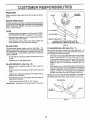
TRACTOR
Always observe safety rules when performing any maintenance.
BLA.DE
_.______
"_
MANDREL
_
. ASSEMBLY
BRAKE OPERATION
If tractor requires more than six (6)feet stopping distance
at high speed in highest gear, than brake must be adjusted.
(See "TO ADJUST BRAKE" in Service and Adjustments
section of this manua0_
_..._
FLATWASHER
TIRES
•
Maintain proper air pressure in all tires (See "PRODUCT SPECIFICATIONS'
on page 3 of this manual).
•
Keep tires free of gasoline, oit, or insect control chemicals which can harm rubber°
•
Avoid stumps, stones, deep ruts, sharp objects and
other hazards that may cause tire damage.
_;
-_'._
EDGEUP
I
_
HEX BOLT (GRADE 8)* --"-"_;_
*A GRADE 8HEATTREATED
BOLT CAN BE
IDENTIFIED BY SIX LINES ON THE BOLT HEAD°
FIGo t0
BLADE CARE
For best results mower blades must be kept sharp. The
blades can be sharpened with a _e or on agrinding wheel.
We suggest they be sharpened or replacedafter every 25
hours of mowing. Check blades more often if mowing in
sandy conditions.
TO SHARPEN
•
Do not attempt to sharpen blades while they are on the
mower,
.
The blade can be sharpened with a file or on a grinding
wheel. Do not attempt to sharpen while on the mower.
•
Replace bent or damaged blades_
-
To check blade balance, you wilt need a 5/8" diameter
steel bolt, pin, or a cone balancer. (When using a cone
balancer, follow the instructions supplied with balancer).
,
SJide blade on to an unthreaded portion of the steel bolt
or pin and hold the bolt or pin parallel with the ground,
If blade is balanced, it should remain in a horizontal
position, if either end of the blade moves downward,
sharpen the heavy end until the blade is balanced.
Remove hex bolt, Iockwasher and flat washer securing
blade.
•
Install new or resharpened blade with trailing edge up
towards deck as shown.
•
Reassemble hex bolt, lock washer and flat washer in
exact order as shown.
(See Fig. 11)
Care should be taken to keep the blade balanced. An
unbalanced blade will cause excessive vibration and eventual damage to mower and engine_
BLADE
REMOVAL
(See Fig. 10)
•
Raise mower to highest position to allow access to
blades.
•
BLADE
NOTE: Do not use a nail for balancing blade. The lobes of
the center hole may appear to be centered, but are not.
CENTER HOLE
•
Tighten bolt securely (30-35 Ft. Lbs. torque),
IMPORTANT: BLADE BOLT IS GRADE 8 HEAT TREATED.
5/8" BOLT
BLADE
OR PiN
J
FIG. 11
15
¢USTO
BATTERY
ER
ESPONS BILITUE$
ENGINE
(See Fig. 12)
Your unit has a battery charging system which is sufficient
for normal use. However, periodic charging of the battery
with an automotive charger will extend it's life.
•
Acid solution level in each battery cell should be even
with bottoms of vent wells. Add only distilled or iron free
water if necessary. Do not overfill.
•
•
Keep battery and terminals clean.
Keep battery bolts tight.
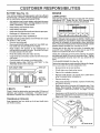
LUBRICATION
Only use high quality detergent o!1 rated with API service
classification SG. Select the oil s SAE viscosity grade
according to your expected operating temperature.
•
Keep vent caps tight and small vent holes in caps open.
,
Recharge at 6 amperes for 1 hour°
TO CLEAN BATTERY AND TERMINALS -
,_o'
"o .=c,
I
o' SAE
, _o'
VISCOSITY
_. 40.G_DES_0' , _,
-_'o" ._a"
_"
1'o'
20"
I
_'..
,,o_
TEMPERATURE RAJ_GE A,NTICIPATEID BEFORE Nt_._'TOIL CHANGE
Corrosion and dirt on the battery and terminals can cause
the battery to "leak" power.
•
Remove terminal guard.
•
Disconnect BLACK battery cable first then RED battory cable and remove battery from tractor_
•
Wash battery with solution of four tablespoons of
baking sodato one gatlon of watero Be careful notto get
the soda solution into the cel]s.
NOTE: Although multi-viscosity oils (5W30, 10W30, etc.
improve starting in cold weather, these multi-viscosity oils
will result in increased oil consumption when used aboe
32°C. Check your engine oil level more frequently to avoid
possible engine damage from running low on oil.
•
,
Check the crankcase oil level before starting the engine
and after each eight (8) hours of continuous use. Tighten
oil fill cap/dipstick securely each time you check the oil
level.
"
•
Change the oil after the first two hours of operation and
every 25 hours thereafter or at least once a year if the
tractor is not used for 25 hours in one year.
Rinse the battery with plain water and dry°
C1eanterminals and battery cable ends with wire brush
until bright.
Coat terminals with grease or petroleum jelly.
Reinstall battery (See "iNSTALL BATTERY" in the
Assembly section of this manual).
CUT AWAY VIEW
TO CHANGE ENGINE OIL (See Fig. 13)
Determine temperature range expected before oil change.
All oil must meet API service classification SG.
CAP
•
Be sure tractor is on level surface.
•
•
Oit will drain more freely when warm°
Catch oil in a suitable container.
•
Remove oil fill dipstick. Be carefut not to allow dirt to
enter the engine when changing oil.
CELL ACID
•
Remove drain plug
LEVEL
•
After oil has drained completely,
and tighten securely.
•
Refill engine with oil through oil fill dipstick tube. Pour
slowly. Do not overfill. For approximate capacity see
"PRODUCT SPECIFICATIONS"
on page 3 of this
manual.
•
Use gauge on oit fill dipstick for checking level. Be sure
dipstick cap is tightened securely for accurate reading°
Keep oil at "FULL" line on dipstick.
WELL
FIG. 12
V-BELTS
Check V-belts for deterioration and wear after 100 hours of
operation and replace if necessary° The belts are not
adjustable. Replace belts if they begin to slip from wear.
TRANSAXLE
replace oil drain plug
COOLING
Keep transaxte free from build-up of dirt and chaff which
can restrict cooling_
OIL FILL
/
/
OIL DRAIN PLUG
FIG. 13
16
AIR FILTER
FOAM
PRE-CLEANER
(See Fig.
14)
BLOWER HOUSING
Your engine will not run properly and may be damaged by
using a dirty air filter° Clean the foam pro-cleaner element
after every 25 hours of operation, more often if used in very
dusty, dirty conditions,
•
Remove knob and cover,
,
Remove cartridge nut and replace cartridge.
•
Reassemble and tighten securely.
SCREWS
SCREWS
AIR SCREEN
/
NOTE= Do not attempt to clean or oil the paper cartridge.
Replace paper cartridge once a year or after every 100
hours of operation, more often if used in very dusty, dirty
conditions_
•
Wash foam pre-cleaner in liquid detergent and water.
•
Wrap foam pre-cleaner in cloth and squeeze dry.
°
Lightly coat foam pro-cleaner with clean engine oil.
Squeeze in towel to remove excess oil. Do not saturate.
,
•
STARTER
HOUSING
OIL FILL
DIPSTICK
ENGINE COOLING
FINS
SPARK
PLUG
FIG. 15
Install foam pre-cleaner over paper cartridge°
Reassemble cover and secure with knobs,
MUFFLER
inspect and replace corroded muffler and spark arrester (if
equipped) as it could create a fire hazard and/or damage,
COVER
KNOB
SPARK
PLUGS
Replace spark plugs at the beginning of each mowing
season or after every 100 hours of operation, whichever
comes first. Spark plug type and gap setting are shown in
PRODUCT SPECIFICATIONS
on page 3 of this manual.
IN-LINE FUEL FILTER
(See Fig. 16)
The fuel filter should be replaced once each season. If fuet
filter becomes clogged, obstructing fuel flow to carburetor,
reptacement is required.
FIG. 14
AIR SCREEN (See Fig. 15)
The englne air screen must be kept free of dirt and chaff to
prevent engine damage from overheating. Clean with a
wire brush or compressed air to remove dirt and stubborn
dried gum fibers.
•
With engine coot, remove filter and plug fuel line
sections.
•
Place new fuel filter in position in fuel line.
.
Be sure there are no fuel line leaks and clamps are
properly positioned.
•
immediately wipe up any spilled gasoline.
CLAMP
ENGINE COOLING FINS (See Fig. 15)
Remove any dust, dirt or oil from engine cooling fins to
prevent engrne damage from overheating.
FIGo t6
CLEANING
•
Remove oil fill dipstick and cover opening to prevent
entry of dirt
*
•
Remove screws from blower housing and lift housing
off engine.
Clean engine, battery, seat, finish, etc. of all foreign
matter.
•
•
Remove the screws securing the starter housing and
lift housing off engine,
Keep finished surfaces and wheels free of all gasoline,
oil, etc.
•
Protect painted surfaces with automotive type wax°
•
Use compressed air or stiff bristle brush to thoroughly
clean engine cooling fins.
•
To reassemble, reverse above procedure.
We do not recommend using a garden hose to clean your
tractor unless the electrical system, muffler, air fi{ter and
carburetor are covered to keep water out. Water in engine
can result in a shortened engine fife,.
17
SERVNCE AN
ADJUSTMSNTS
.._==H..u= ...11..
N==u,i
i.u.,.
CAUTION:
°
BEFORE PERFORMING ANY SERVICE OR ADJUSTMENTS:
Depress clutch/brake
pedal fully and set parking
lever in "NEUTRAL"
brake.
.
Place gearshift
.
Place attachment clutch in "DISENGAGED"
Turn ignition key "OFF" and remove key.
a
Make sure the blades and all moving parts have completely stopped.
Disconnect spark plug wire from spark plug and place wire where it cannot come in contact with
plug.
o
position.
position.
TRACTOR
TO REMOVE
SEE NOTE ABOVE
MOWER
CORRECT
)_TRUNNION
(See Fig. 17)
TRUNNION
Mower wilt be easier to remove from the right side of tractor,
•
•
Place attachment clutch in "DISENGAGED" position.
Move attachment lift lever forward to lower mower to its
lowest position.
•
Roll belt off engine pulley.
•
Disconnect clutch rod from clutch lever by removing
retainer spring,
•
Disconnect suspension arms from rear deck brackets
by removing retainer springs_
,
Disconnect front links from deck by removing retainer
springs_
•
i., u=
=
POSITION
"_--PARALLEL
CLUTCH
ROD
RETAINER
SPRING
Raise lift lever to raise suspension arms. Slide mower
out from under tractor,
IMPORTANT;
iF AN ATTACHMENT OTHER THAN THE
MOWER IS TO BE MOUNTED TO THE TRACTOR, TIdE
R.H, AND Loll, SUSPENSION ARMS MUST BE REMOVED
FROM TRACTOR.
RETAINER
SPRINGS
TO INSTALL
MOWER
(See Fig. 17)
•
Raise attachment lift lever to its highest position°
•
Slide mower under tractor with discharge guard to right
side of tractor.
•
Lower lift lever to its lowest position.
.
Install mower in reverse order of removal instructions.
RETAINER
SPRINGS
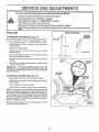
NOTE: The mower clutch rod has a trunnion that has been
preset at the factory for optimum mower performance. DO
NOT MOVE THE TRUNNION ON THE CLUTCH ROD. If
for any reason the trunnion has been moved on the clutch
rod, it must be reset to correct position (parallel with clutch
rod) and measure 10-11/32" (Check dimension on edge of
flat work surface as shown)
ENGINE
PULLEY
Be sure to tighten trunnion nut securely against trunnion
after making any adjustments.
FIG. 17
18
SERVICE AN
TO LEVEL MOWER
ADJUSTMENTS
HOUSING
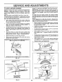
FRONT-TO-BACK ADJUSTMENT (See Figs_ 20 and 2'1) IMPORTANT: DECK MUST BE LEVEL SIDE-TO-SIDE. IF
THE FOLLOWING FRONT-TO-BACK ADJUSTMENT IS
NECESSARY, BE SURE TO ADJUST BOTH FRONT LINKS
EQUALLY SO MOWER WILL STAY LEVEL SIDE-TOSIDE.
To obtain the best cutting results, the mower housing
should be adjusted so that the front is approximately 1/4" to
3/4" lower than the rear when the mower is in its highest
position.
Adjust the mower' while tractor is parked on level ground or
driveway.
Make sure tires are properly inflated (See
"PRODUCT SPECIFICATIONS" on page 3). If tires are
over or under inflated, you will not properly adjust your
mower.
SIDE-TO-SIDE ADJUSTMENT (See Figs. 18 and 19)You will need two (2) standard 2 x 4 short pieces of wood
to make the following adjustment. Similar blocks measuring 1-1/2" thick may also be used_
o
Raise mower with attachment lift control to allow two
(2) 1-1/2" thick blocks to be placed under rear edge of
mower directly behind mandrels..
Check adjustment on right side of tractor. Measure distance"D directly in front and behind the mandrel at bottom
edge of mower housing as shown.
Before making any necessary adjustments, check that
both front links are equal in length. Both links should
be approximately 10-3/8 ",
Lower mower deck to its lowest height of cut posit!on
(See 'q'O ADJUST MOWER CUTTING HEIGHT' in
Operation section of this manual)_
On both sides of tractor, loosen, but do not remove, the
fasteners securing the adjustable pivot brackets to
frame. Both brackets must be loose enough to move
freely.
O
If links are not equal in length, adjust one link to same
length as other link1
o
To tower front of mower loosen nut "E" on both front
links an equal number of turns..
When distance "D" is 1/4" to 3/4" lower at front than
rear, tighten nuts "F" against trunnion on both front
links.
,
Pull down firmly on suspe_'sion arm to remove any
slack in pivot bracket and h_ld while tightening rear
fastener first to secure. Tighte, remaining fastener°
0
=
•
Repeat procedure on other side of tractor.
Raise mower with attachment lift control and remove
blocks from under mower°
-
PLACE TWO (2) 1_1/2" THICK BLOCKS UNDER REAR EDGE OF
DECK (Use wood2 x 4'sor equivalent)
•
To raisefrontof mower, loosen nut "F"from trunnion on
both front links. Tighten nut "E" on both front links an
equal number of turns°
When distance "D" is 1/4" to 3/4" lower at front than
rear, tighten nut "F" against trunnion on both front links.
Recheck side-to_side adjustment.
MANDREL
FIG. 20
BOTH
FRONT LINKS MUST BE EQUAL
IN LENGTH
MOWERMUSTBE|N LOWESTHEIGHTOFCUTPOS_N
FIG. 18
ADJUSTABLEPIVOT
BRACKET
FASTENERS
SUSPENSION
ARM,
NUT"E"
PULLDOWN AND
_GHTEN REAR
FASTENER FIRST
FIG. 19
FRONTUNKS
19
TRUNNION
FIG. 21
SERVHCE AND ADJUSTMENTS
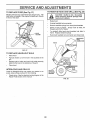
TO REPLACE
(See Fig. 22)
MOWER
BLADE
DRIVE
BELT
WITH PARKING
BRAKE "ENGAGED"
The mower blade drive belt may be replaced without tools
Park the tractor on level surface_ Engage parking brake.
For assistance, there is a belt installation guide decal on the
mower housing.
BELT REMOVAL.
Place attachment clutch in "DISENGAGED"
.
Move attachment lift lever forward to lower mower to its
lowest position,
•
Roll belt off engine puIiey.
°
Disconnect R_H_suspension arm from rear deck bracket
by removing retainer spring.
°
Work belt off both mandrel pulleys and idler pulleys.
NUT 'A"
position_
JAM NUT
OPERATING
•
Pull belt away from mower°
BELT INSTALLATION -
ARM
•
Install new belt in reverse order of removal,
°
Make sure belt is in all pulley grooves and inside all belt
guides°
MANDREL
RoHoSUSPENSION
ARM
ENGINE
FIG. 23
TO REPLACE MOTION DRIVE BELT (See
PULLEY
Fig. 24)
PULLEY
Park the tractor on level area. Engage parking brake_
For assistance, there is a belt installation guide decal on
bottom side of ieff footrest.
•
Remove mower (See "TO REMOVE MOWER" in this
section of this manual).
.
Remove belt from stationary idler and clutching idter.
•
Remove beit from engine pulley,
•
Roll belt over top of transaxle pulley,
•
Install new belt by reversing above procedure.
PULLEYS
RETAINER
SPRING
IMPORTANT:
REPLACE
IN THES MANUAL,
ONLY
MANDREL
PULLEY
WITH
BELT
LISTED
CHASSIS
FIG. 22
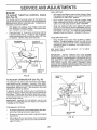
TO ADJUST
BRAKE
(See Fig. 23)
Your tractor is equipped with an adjustable brake system
which is mounted on the right side of the transaxle.
If tractor requires more than six (6) feet stopping distance
at high speed in highest gear, then brake must be adjusted.
•
Depress clutch/brake pedal and engage parking brake.
°
Measure distance between brake operating arm and
nut "A" on brake rod.
•
If distance is other than 1-1/2", disengage parking
brake, loosen jam nut and turn nut "A" until distance
becomes 1-1/2. Retighten jam nut against nut A,
•
Engage parking brake and recheck distance_
•
Road test tractor for proper stopping distance as stated
above_ Readjust if necessary. If stopping distance is
still greater than six (6) feet in highest gear, further
maintenance is necessary, Contact your nearest authorized service center,
CLUTCHIN(
PULLEY
STATIONARY
IDLER
ENGINE
PULLEY
FIG. 24
2O
•
i
SERVICE AND ADJUSTMENTS
L
I,nm,
TO ADJUST
, ,=l
STEERING
U
WHEEL
lU ,1'
I I,r,,ll_
,, ,,
ALIGNMENT
.......................
if steering wheel crossbars are not horizontal (left to right)
when wheels are positioned straight forward, remove steer-
,_
ingwheelandreassembteperinstructionsintheAssembly
WHEEL
FOR REPAIRS
Block up ax{e secure{y,
•
Remove axle cover, retaining ring and washers to allow
wheel removal (rear wheel contains a square key - Do
not lose)
•
Repair tire and reassemble
•
On rear wheels on{y: align grooves in rear wheel hub
and axle Insert square key,
Replace washers and snap retaining ring securely in
axle groove,
•
•
tf your battery is too weak to start the engine, it should be
recharged.
If "jumper cables"
are used for emergency
starting, foliow this procedure:
IMPORTANT:
YOUR TRACTOR
IS EQUIPPED WITH A
12 VOLT NEGATIVE GROUNDED
SYSTEM, THE OTHER
VEHICLE
MUST
ALSO BE A 12 VOLT
NEGATIVE
GROUNDED
SYSTEM.
DO NOT USE YOUR TRACTOR
BATTERY TO START OTHER VEHICLES.
(See
•
BATTERY
ateexp|oslvegases,
Keep sparks, flame
and smoking materials away from batteries.
wear batteries
eye protection
CAUTION;Always
Lead-acid
generwhen around batteries,
I
TOE-IN/CAMBER
The front wheel toe-in and camber are not adjustable on
your tractor
If damage has occurred to affect the front
wheel toeqn or camber, contact your nearest authorized
service center,
TO REMOVE
Fig. 25)
I ,I
WITH A WEAK
I ......................................
section of this manual
FRONT WHEEL
......................,,U
TO START ENGINE
(See Fig. 26)
TO ATTACH
"
JUMPER
CABLES
-
Connect each end of the RED cable to the POSITIVE
(+) terminal of each battery, taking care not to short
against chassis
Connect one end of the BLACK cable to the NEGATIVE (-) terminal of fully charged battery.
Connect the other end of the BLACK cable to a good
CHASSIS GROUND, away from fuel tank and battery.
TO REMOVE CABLES, REVERSE ORDER -
Replace axle cover
BLACK cable first from chassis and fully charged
battery
RED cable last from both batteries
NEGATIVE TERMINAL
POSITIVE TERMINAL
WASHERS
RETAINING
RING
I
AXLE COVER
'_
SQUARE KEY
(REARWHEELONLY)
FIG. 25
CHARGED
BATTERY
POSITIVE TERMINAL
NEGATIVE TERMINAL
FIG. 26
21
SERVICE AND ADJUSTMENTS
TO REPLACE
FUSE
(See
TO REMOVE
Fig. 27)
.....................
llUln
u illll,
HOOD AND GRILL
ii
(See Fig. 28)
i
|
Replace with 30 amp automotive-type plug-in fuse, The
fuse holder is iocated in the engine compartment, directly
in front of the dash_
I
I
I
FUSE
HOLDER
G'
_
_
CAUTION:
Muffler Is hot. Be careful
when removing retainer springs from
,oo pivo,
brackets
i,
•
Raise hood.
.
Unsnap headlight wire connector.
•
Remove retainer springs from hood pivot brackets.
•
Stand in front of tractor.
Grasp hood at sides, tilt
forward and lift off of tractor
•
To reinstall, slide hood pivot brackets into slots in
frame. Repiace retainer springs.
°
Reconnect headlight wire connector and c_ose hood_
HEADLIGHT
WiRE
CONNECTOR
HOOD
FIG. 27
TO REPLACE
HEADLIGHT
BULB
•
Raise hood,'
•
Pull bulb holder out of the hole in the backside of the
grill.
.
Replace bulb in holder and push bulb holder securely
back into the hole in the backside of the grill
Close hood.
•
INTERLOCKS
AND RELAYS
REMOVE
R ETAIN ER
SPRINGS
Loose or damaged wiring may cause your tractor to run
poorly, stop running or prevent it from starting
•
Check wiring Seethe e{ectrica] wiring diagram inthe
Repair Parts section of this manual
FIG, 28
22
!
ulll
SERVICE AN
illlllll
ADJUSTMENTS
FINAL SETTING -
ENGINE
TO ADJUST
THROTTLE
(See Fig. 29)
CONTROL
CABLE
The throttle control has been preset at the factory and
adjustment should not be necessary, Check adjustment as
described below before loosening cable. If adjustment is
necessary, proceed as follows:
•
With ,engine,not, running_, move throttle control lever
from SLOW to CHOKE position. Slowly movelever
from "CHOKE" to "FAST" position.
•
Checkthat holes"A" in governor control lever and hole
in governor plate line-up if holes "A" are not aligned,
loosen clamp screw and move throttle cable until ho_es
are aligned. Tighten clamp screw securely.
•
Start engine and allow to warm for five minutes. Make
final adjustments with engine running and shift/motion
control lever in "NEUTRAL" position.
•
Move throttle control lever to "SLOW" position. With
finger, rotate and hold throttle lever against idle speed
screw, Turn idle speed screw to attain 1750 RPM.
•
While still holding throttle lever against idle speed
screw, turn idle mixture valve In (clockwise) until engine begins to die and then turn out (counterclockwise)
until engine runs rough. Turn valve to a point midway
between those two positions. Release throttle lever.
ACCELERATION
•
GOVERNOR
CONTROLLEVER
GOVERNOR
CONTROL PLATE
TEST -
Move throttle control lever from "SLOW" to "FAST"
position, if engine hesitates or dies, turn idle mixture
valveout (counterclockwise) 1/Sturn, Repeattest and
continue to adjust, if necessary, until engine accelerates smoothly
High speed stop is factory adjusted.
damage may result
Do not adjust -
IMPORTANT:
NEVER TAMPER
WITH THE ENGINE
GOVERNOR,
WHICH IS FACTORY
SET FOR PROPER
ENGINE SPEED OVERSPEEDING
THE ENGINEABOVE
THE
FACTORY
HIGH
SPEED
SETTING
CAN BE
DANGEROUS.
IF YOU THINK THE ENGINE.GOVERNED
HIGH SPEED NEEDS ADJUSTING,
CONTACT
YOUR
NEARESTAUTHORIZED
SERVICE CENTER, WHICH HAS
PROPER EQUIPMENT AND EXPERIENCE
TO MAKE ANY
NECESSARY
ADJUSTMENTS,
HOLES"A"
CLAMP
SCREW
THROTTLE
CABLE
FIG. 29
TO ADJUST
CARBURETOR
THROTTLE
LEVER
IDLE SPEED
SCREW
(See Fig. 30)
The carburetor has been preset at the factory and adjustment should not be necessary. However, minor adjust*
ment may be required to compensate for differences in fuel,
temperature, altitude or load. ff the carburetor does need
adjustment, proceed as follows:
In general, turning idle mixture vafve in (clockwise) decreases the supply of fuel to the engine giving a leaner fuel/
air mixture. Turning the idle mixture valve out (counterclockwise) increases the supply of fuel to the engine giving
a richer fuel!air mixture.
IMPORTANT: DAMAGE TO THE NEEDLE VALVE AND
THE SEAT IN CARBURETOR MAY RESULT IF SCREW IS
TURNED IN TOO TIGHT.
PRELIMINARY
SETTING -
•
Air cteaner assembly must be assembled tothe carburetor when making carburetor adjustments.
•
Be sure the throttle control cable is adjusted properly
(see above).
•
With engine off turn idle mixture valve in (clockwise)
closing it finger tight and then turn out (counterclockwise) 1 fullturn.
IDLE MIXTURE
VALVE
FIG, 30
23
STORAGE
i
I
,,
,
....
Remove mower from tractor for winter storage_ When
mower is to be stored for a period of time, clean it thoroughly, remove all dirt, grease, leaves, etc_ Store in a
clean, dry area.
Lubricate as shown in the Customer Responsibilities
section of this manual°
•
Be sure that all nuts, bolts and screws are securely
fastened. Inspect moving partsfordamage, breakage
and wear. Replace if necessary.
•
,i .................
iiiii
i
•
Start the engine and let it run until the fuel lines and
carburetor are empty.
.
Never use engine or carburetor cleaner products in the
fuel tank or permanent damage may occur.
Use fresh fuel next season.
•
Clean entiretractor (See "CLEAN1NG" in the Customer
Responsibilities section of this manual).
,
,i
FUEL SYSTEM
TRACTOR
Inspect and replace belts, if necessary (See belt replacement instructions in the Service and Adjustments
section of this manual)
i I ,,i,1,,,
IMPORTANT:
IT IS IMPORTANT TO PREVENT GUM
DEPOSITS FROM FORMING
IN ESSENTIAL FUEL
SYSTEM PARTS SUCH AS CARBURETOR, FUEL FILTER,
FUEL HOSE, OR TANK DURING STORAGE.
ALSO,
EXPERIENCE INDICATES THAT ALCOHOL BLENDED
FUELS (CALLED GASOHOL OR USING ETHANOL OR
METHANOL) CAN ATTRACT MOISTURE WHICH LEADS
TO SEPARATION AND FORMATION OF ACIDS DURING
STORAGE
ACIDIC GAS CAN DAMAGE THE FUEL
SYSTEM OF AN ENGINE WHILE IN STORAGE.
•
Drain the fuel tank.
gasoline In the tank inside a building
where
fumesNever
may store
reachthe
an tractor
open flame
CAUTION:
with
or spark.
Allow the engine to cool
before storing In any enclosure.
•
ii
ENGINE
Immediately prepare your tractor for storage at the end of
the season or if the tractor will not be used for 30 days or
more.
°
iiiii
NOTE: Fuel stabilizer is an acceptable alternative in
minimizing the formation of fuel gum deposits during storage. Add stabilizer to gasoline in fuel tank or storage
container. Always follow the mix ratio found on stabilizer
container. Run engine at least 10 minutes after adding
stabilizer to allow the stabilizer to reach the carburetor. Do
not drain the gas tank and carburetor if using fuel stabilizer,
ENGINE
OIL
Drain oil (with engine warm) and replace with clean engine
oil. (See "ENGINE" in the Customer Responsibilities
section of this manual).
Touch up all rusted or chipped paint surfaces; sand
lightly before painting.
BATTERY
CYLINDERS
•
Fully charge the battery for storage_
•
Remove spark pfug(s).
•
After a period of time in storage, battery may require
recharging.
•
Pour one ounce of oil through spark plug hole(s) into
cylinder(s).
•
To help prevent corrosion and power leakage during
long periods of storage, battery cables should be
disconnected and battery cleaned thoroughly (see "TO
CLEAN BATTERY AND TERMINALS" in the Customer Responsibilities section of this manual).
•
Turn ignitionkey to"START"
to distribute oilo
.
Replace with new spark plug(s).
After cleaning, leave cables disconnected and place
cables where they cannot come in contact with battery
terminals.
OTHER
•
•
Be sure battery drain tube is securely attached.
position for a few seconds
•
Do not store gasoline from one season to another.
•
Replace your gasoline can if your can starts to rust.
Rust and/or dirt in your gasoline will cause problems.
°
If possible, store your tractor indoors and cover it to
give protection from dust and dirt.
•
Cover your tractor with a suitable protective cover that
does not retain moisture. Do not use plastic. Plastic
cannot breathe which allows condensation to form and
will cause your tractor to rust.
IMPORTANT: NEVER COVER TRACTOR WHILE ENGINE
AND EXHAUST AREAS ARE STILL WARM.
24
TROUBLESHOOTmNG POmNTS
CAUSE
PROBLEM
Will not start
1
Out of fuel.
2
3.
4,
5,
6.
7.
Engine not"CHOKED"
Engine ftooded.
Bad spark plug_
Dirty air filter,
Dirty fuel fitter.
Water in fuel
8.
9.
10.
CORRECTION
properly.
l ll,i
Fill fuel tank.
See =TO START ENGINE" in Operation section,
Wait several minutes before attempting to start,
4.
5,
6.
7.
Replace spark plug.
Cteantreplace airfilter,
Replace fue! tilter
Drain fuel tank and carburetor, refill tank w_th fresh
gasoline and replace fuel filter.
Check all wiring,
Contact Sears Service Center/Department
Contact Sears Service CentedDepartmenL
8.
9.
10,
Loose or damaged wi_ng,,
Carburetor out of adjustment_
Engine valves out of adjustment.
i ....
1.
2.
3_
i,i r,,ll ,,,i
1.
2
3
4,
5
6.
7.
8
Dirty air filter.
Bad spark plug.
Weak or dead battery
Dirty fuelfilter,,
Stale or dirty fuel.
Loose or damaged widngo
Carburetor out of adjustment.
Engine valves out of adjustment.
I.
2.
3.
4.
5.
6.
7.
8.
Clean/replace air filter.
Replace spark plug.
Rechargeor replace battery.
Replace fuel filter.
Drain fuel tankand rel]ll with lresh gasoline.
Check all wlringo
Contact Sears Serv}ce CentedDepartmenL
Contact Sears Service CentedDepartment.
Engine will not turn over
1.
2.
3.
4,
5,
6
7
8.
9.
Clutch/brake pedalnot depressed
Attachment clutchis engaged.
Weakordead battery.
Blown fuse.
Corroded battery terminals.
Looseor damaged wiring°
Faultyignitionswitch.
Faultysolenoidor starter.
Faulty operator presence switch(as).
1.
2.
3,
4.
5.
6.
7.
8
9,
Depress clutchlbrake pedal
Disengage attachment clutch.
Recharge or replace battery,.
Replace fuseClean battery terrains[so
Check all wiring,
Check/replace ignil_onswitch.
Check/topless solenoid or starter
Contact Sears Service CentadDepartment.
Engine clicks but will not
start
1
2.
3.
4.
Weak or dead battery,
Corroded battery terminals.
Loose or damaged wiring_
Faulty solenoid or starter.
1.
2o
.3.
4.
Recharge or replace ba[tery.
Clean battery terminals.
Check all wiring.
Check/replase solenoid orstarter.
Loss of power
12.
3.
4
5
6
7
8o
9-
Cuing too much grass/too fast.
Throttle in "CHOKE" position,
Build-up of grass, leaves and trash under mower,
Dirty air filter.
Low oi! _eveild!rty oil
Faulty spark plug,
Dirty fuel filter.
Stale ordirty fuel
Water in fueL.
1
2
3.
4.
5.
6.
7.
8,
9.
10,
11.
12,
13,
14,
Set in "Higher Cut" position/reduce speed.,
Adjust threttTe contmI.
Clean underside of mower housing.
Clean/replace air filter.
Check oil levellchange oil
Clean and regap orchangs spark plug.
Replace fuel 51tar.
Drain fuel tank and refill with fresh gasoline,
Drain fuel tank and carburetor, refill tank with frs_h
gasoline and replace fuel filter.
Connect and tighten spark plug wire.
Clean engine air soreenifins.
Clean/replace muffler.
Check al! wiring
Contact Sears Service Center/Department.
15.
Contact Sears Service Center/Department,
Hard to start
i
, ,i i,l,,irl,
10.
11.
12
1314.
15.
Spark plug wire loose,
Dirty engine air screeninns.
Dirty/c_ogged muffler.
Loose or damaged wiring.
Carburetor out of adjustmenL
Engine valves out of adjustment
ILL_
Excessive
vibration
t2.
3
Worn, bent orloose blade.
Bent blade mandrel.
Loose/damaged part(s).
25
1.
2.
Replace blade. Tighten blade bolt.
Replace blade mandrel.
3
Tighfen loose part(s).
Replace damaged parts.
.ll.".....n..u ..........
.
i_ I_
u .....
TROUBLESHOOTBNG
,,p.l,.i
PROBLEM
.........i.
i.......i........
CAUSE
n .
POINTS
i..
''
i
CORRECTION
i...............
Engine conUnues to run
when operator leaves seat
with attachment clutch
lurnl.u....i.n
Faulty operator-safety
i,,,,,,ll,,,i,,, i,,,n,
,,
presence control system.
1.
Check wiring, switches and connections.
I1not
corrected, contact Sears Service Center/Department.
engaged
Poorcut-uneven
Mower bladeswlll not
rotate
Poor grass discharge
Headlight(s) not worldng
(if so equipped)
,n,,,,ull=,,,,,,, i
Battery willnot charge
Engine "backfires"
when turning engine
"OFF"
,
1.
2.
Worn, bent orloose blade,
Mower deck not level.
1.
2.
Replace blade. Tighten blade boil
Level mower deck,
3,
4.
Buildup of grass, leaves, and trash under mower.
Bent blade mandrel.
5.
Clogged mower deck vent holes from buildup of
grass, leaves, and trash around mandrels.
3.
4
5,
Clean underside of mower housing°
Replace blade mandrel.
Clean around mandrels to open vent hotes_
1,
Remove obstruction_
2.
3
4.
Replace mower drive belt.
Replace idler pulley.
Replace blade mandrel,
1.
Obstruction
2.
3,
4,
Wain/damaged mowerdnve
Frozen idler pulley
Frozen blade mandrel
in clutch mechanism.
t
2o
3.
4,
Engine speed too slow
Travel speed too fast
Wet grass
Mower deck not level
5,
6
7
8,.
Low/uneven tire air pressure
Worn, bent or loose blade
Buttdup of grass, leaves and trash under mower.
Mower dr;ve belt worn,
9
10
t 1.
Blades improperly instafled,
improper blades used
Clogged mower deck vent holes from buildup of
grass, leaves, and trash around mandrels.
belt,
1
2.
&
4
5
6
7
8.
9.
10.
11,
Race threlt[e control in "FAST" position.
Shift to slower speed.
Allow grass to dry before mowing.
Level mower deck,
Check tires for proper air pressure.
Rep]acetsharpen blade, Tighten blade bolt.
Clean underside of mower housing.
Replace mower drive bell
Reinstall blades sharp edge down.
Replace with blades listed in this manual.
Clean around mandrels to open vent holes.
1.
Switch is "OFF".
1
"rum switch "ON",
2.
&
4.
5,
Bulb(s) bumedout.
Faulty light SwitCh,r
Loose or damaged wiring
Blown fuse.
2.
3
4.
5.
Replace bulb(s),
Checldrepiace light switch,
Check wiring and connections.
Replace fuse.
1
2,
Bad battery ceil(s)
Poor cable connections
1,
2.
Replace battery.
Check/clean all connection&
3.
4.
Faulty regulator (if so equipped).
Faulty alternator
3
4,
Replace regulator,
Replace alternator,
,
Engine throttle control not set at "SLOW'
posilion for 30 seconds before stopping engine,
26
Move throttle control to 'SLOW' positionand allow
toidle for30 seconds belore stepping engine_
12 HP 38" TRACTOR
= - MODEL NUMBER
9! 7.255561
SCHEMATIC
01110
111°
RED
BATTERY
.....
RED
,
.Eo
FUSE 30 AMP.
©I
I
a
|
STARTER
WHITE
SOLENOID
IGNITION SWITCH
I ......
l
I
{,_,_i
I......
]
(PEDAL UP)
CLUTC_BRAKE
BLACK
'I
I
I
I
I
l
{
1
t
f
I
II
,
BLACK
(_
IGNITION
UNIT
|
I
I
_ BLACK
SEAT
SWITCH
(NOT OCCUPIED)
_____ _'
] ATT'MENT CLUTCH
(CLUTCH OFF)
BLACK
I .........
___
SPARK
PLUG
RED
ALTERNATOR
3@AMPS3600
RPMDC
_
(BATTERY
IGNITION SWITCH
POSITION
CIRCUIT
OFF
ON
START
M+G
B+ L
B+S
NON-REMOVABLE
CONNECTIONS
IN UN_
NOTE
YOUR TRACTOR IS EQUIPPED
WITH A SPECIAL ALTERNATOR
SYSTEM THE LIGHTS ARE NOT
CONNECTED TO THE BATTERY,
BUT HAVE THEIR OWN
ELECTRICAL SOURCE.
BECAUSE OF THIS, THE BRIGHT-.
NESS OF THE LIGHTS WILL
CHANGE WiTH ENGINE SPEED.
AT IDLE THE LIGHTS WILL DIM.
AS THE ENGINE IS SPEEDED UP,
THE LIGHTS WILL BECOME
THEIR BRIGHTEST.
_
REMOVABLE
CONNECTIONS
27
20 VOLTS AC (M_N,)
"_
SAMPS ALTERNATOR
1_ VOLTS
WIRING INSULATED
AC 0 3600 RPM.,
CLIPS
NOTE: If wiring insulated clips were removed for servicing of unit, they should
be replaced to properly secure your wiring.
i
REPAIR PARTS
12 HP 38" TRACTOR
= - MODEL NUMBER
917.255561
ELECTRICAL
A
@
B
12
C
13
32
33
18
@14
28
I
I
t
I
t
!
31
8
34
\
\
\
\
/
\
\
/
\
\-
22
I
/
6
I
[
28
19
REPAIR PARTS
12 HP 38" TRACTOR
- - MODEL
NUMBER
917.255561
ELECTRICAL
KEY PART
NO. NO.
1
2
3
4
5
6
7
8
9
10
11
12
13
t21265X
STD365402
124211X
132017
4207J
132202
4799J
129965
109596X
109081X
STD551125
73350400
74780408
14
15
16
17
'18
STD551225
STD541425
131563
109553X
STD601005
19
20
104445X
STD601005
2t
22
23
24
25
26
27
28
29
30
31
32
33
34
35
121305X
121264X
74760412
STD551025
STD551125
STD541025
t09310X
108824X
109238X
123620X
110712X
127441X
7662J
108236X
STD601005
36
37
130890
STD601005
DESCRIPTION
Battery
Switch, Ignition
Nut, Ignition
Harness, Ignition
Cabte, Ground
Cable, Battery
Cable, Battery
Box, Battery
Clamp. Hose
Solenoid
Washer, Lock 1/4
Nut, Hex, Jam 1/4-20 UNC
Bott, Hex Head, Fin.
l/4-20 UNC x 1/2 Grade 5
Washer, Lock, External Tooth 1/4
Nut, Hex, Keps 1/4-20 UNC
Cover, Terminal
Switch, Interlock, Clutch
Screw, Hex Head, Self-Tapplng
#10-24 UNC x 1/2
Switch, Interlock, Clutch
Screw, Hex Head, Self-Tapping
#10-24UNC x 1/2
Switch, Plunger
Cap, Battery
Bolt, Hex Head 1/4-20 UNC x 3/4
Washer 9/32 x 5/8 x 16 Gauge
Washer, Lock, Heavy Helical Spring 1/4
Nut, Hex, Fin. 1/4-20 UNC
Key, Ignition
Fuse, 30 Amp
Tube, Plastic
Cover, Key Switch
Switch, Light
Harness, Light Socket
Bulb, Light
Bracket, Clutch Switch
Screw, Hex Head, Self-Tapping
#I0-24UNC x 1/2
Bracket Switch interlock
Screw, Hex Head, Self-Tapping
#10-24UNC x t/2
NOTE: All component dimensions given in U.S inches
1 inch = 25.4 mm
29
REPAURPARTS
12 HP 38" TRACTOR
CHASSIS
- - MODEL NUMBER
917.255581
AND ENCLOSURES
A
9
lo _'._
6
13
\
30
31
34
A
2
30
REPAIR PARTS
12 HP 38" TRACTOR
CHASSIS
-= MODEL NUMBER
917.255561
AND ENCLOSURES
KEY PART
NO. NO.
1
2
3
4
5
6
7
8
9
10
11
12
13
14
15
135034
127866
17490612
STD523707
STD541437
124465X014
17490608
2751R
123042X012
5479J
'122795X
t21794X
124031X012
17490608
74180512
t6
17
18
19
20
21
22
23
24
25
26
27
28
29
30
31
32
33
34
35
36
38
39
40
50
STD541431
131445X417
126938X
STD512505
STD551125
122933X
124479X
4921H
STD523707
19131312
STD541437
17490608
123915X
124029X
109872X417
109873X
17490612
105476X417
'105475X417
STD533707
STD541437
'134618
134617"
72140606
STD541437
DESCRIPTION
Chassis Assembly
Drawbar
Screw, Thd., Rol!. 3t8-16 x 3/4
Bolt, Hex, Fin. 3/8-16 UNC x 3/4
Nut, Crownlock 3/8-'16 UNC
Saddle
Screw, Thd. Roll 3/8-16 x 1/2
Clip, Fuel Line
Dashboard
Plug, Button
Panel, Dash, LH
Cover, Access
Panel, Dash, RH
Screw, Thdo, Roll. 3/8-16 x 1/2
Screw, Machine, Truss Head
5/16-18 UNC x 3/4
Nut, Hex, Keps 5/'16-18 UNC
Hood Assembly
Bumper, Hood
Bolt, Hex, Fin. 1/4-20 UNC x 1/2
Washer, Lock, Heavy Helical Spring 1/4
R_et, Ratchet, Nylon
Washer, Nylon
Retainer, Spring
Bolt, Hex, Fin. 3/8-16 UNC x 3/4
Washer 13/32 x t3/16 x 12 Gauge
Nut, Crownlock 3/8-16 UNC
Screw, Thd. Roll. 3/8-16 x 1/2
Grill
Lens, Headlight Bar, Clear
Fender
Bracket, Fender
Screw, Thd., Roll 318-16 x 3/4
Footrest, Perforated, LH
Footrest, Perforated, RH
Bolt, Carriage 3/8-16 x 3/4
Nut, Crownlock 3/8-16 UNC
Bracket Assembly, Pivot, Mower, Rear, LH
Bracket Assembly, Pivot, Mower, Rear, RH
Bolt, Carriage 3/8-16 x 3/4
Locknut, Hex, with Washer Insert
3/8-16 UNC
NOTE: All component dimensions given in U,S. inches
! inch = 25_4 mm
31
REPAUR PARTS
12 HP 38" TRACTOR
= = MODEL
DRIVE
57
NUMBER
917.255561
D
_
_:::_
.
41
42
38
39 _
13
70
_63
42
62
_.,...64
55
50
45
44
34
9
49
10
35
J
2
77
28
7
|1
48
45
<
29
23
53
:7 36
77
25
22
24
78
1
75
76
75 74
75
A
B
C
D
E
71
(_
72
F
18
_
61
19 _)60_
32
I
G
67
68
@ 33
REPAIR PARTS
12 HP 38" TRACTOR
- - MODEL NUMBER
917.255561
DRIVE
KEY PART
NO. NO.
1
120897X
2
3
4
5
6
110422X
123666X
12000028
121520X
17490512
7
8
9
10
1'1
12
13
106919X
124461X
19151216
STD561210
105701X
19091210
7'1040412
14
STD551125
15
16
17
18
19
20
STD523727
STD541437
121520X
STD523707
STD541437
17490512
21
22
23
106933X
131867
STD541437
24
25
26
27
28
29
30
31
32
33
34
35
36
37
38
STD541237
106888X
STD551037
STD561210
128904
124236X
109167X
127275X
STD523707
STD541437
122424X
120183X
STD551062
STD571810
123674X
KEY PART
NO. NO.
DESCRIPTION
Transaxle, Dana, 5 Speed,
Model Number 4360-06
Spring, Brake Return, Transaxle
Pulley, Transaxle
R}ng, Retainer
Strap, Torque
Screw, Hex Head, Thd. Roll.
5/16-18 x 3/4
Plate, Shift
Rod, Shifter
Washer !5/32 x 3/4 x 16 Gauge
Pin, Cotter 1/8 x I
Washer, Shift Plate
Washer 9/32 x 3/4 x 10 Gauge
Bolt, Hex Head, Fin.
1/4-28 UNFx 3/4 Grade 8
Washer, Lock, Heavy Helical Spring
1/4
Bolt, Hex, Fin° 3/8-16 UNC x 2-3/4
Nut, Crownlock 3/8-16 UNC
Strap, Torque
Bolt, Hex, Fin. 3/8-16 UNC x 3/4
Nut, Crownlock 3/8-16 UNC
Screw, Hex Head, Thd. Rollo
5/16-18 x 3/4
Knob, Round
Rod, Brake
Lccknut, Hex, with Washer Insert
3/8-16 UNC
Nut, Hex, Jam 3/8-I6 UNC
Spring, Brake Rod
Washer 13/32 x 13/16 x 16 Gauge
Pin, Cotter 1/8 x 3/4
Rod, Parking Brake
Cap, Parking Brake, Red
Bracket, Transmission
Keeper, Belt, LH
Bolt, Hex, Fin.. 3/8-16 UNC x 3/4
Nut, Crownlock 3/8-16 UNC
Shaft Assembly, Foot Pedal
Bearing, Nylon
Washer 21/32 x 1 x 16 Gauge
Pin, Roll 3/16 x 1
Pulley, Idler, Flat
39
40
4'1
42
43
44
45
46
47
48
49
50
51
52
53
54
55
56
57
58
59
60
61
STD523727
4470J
109070X
19131312
STD541437
105706X
110812X
12000039
127783
123789X
123205X
STD523715
STD541437
STD55!037
105710X
STD561210
105709X
STD561210
125907X
t27274X
136715
1913'1312
1749O612
62
63
64
65
8883R
134825
7'1170764
STD551143
66
67
68
69
70
71
72
73
74
75
76
77
78
129921
STD523710
19t31312
STD541437
134683
STD523710
19132012
STD541437
109502X
121749X
STD581075
123583X
121748X
DESCRIPT;ON
Bolt, Hex, Fin.. 3/8-16 UNC x 2-3/4
Spacer, Split
Keeper, Belt Retainer
Washer 13/32 x 13/16 x '12 Gauge
NUt, Crownlock 3/8-16 UNC
Bearing, Nylon
Washer, Hardened
Ring, Klip
Pulley, Idler, V-Groove
Bellcrank Assembly
Retainer, Belt
Bolt, Hex Head 3/8-16 UNC x 1-1/2
Nut, Crownlock 3/8-16 UNC
Washer 13/32 x 13/16 x 16 Gauge
Link, Clutch
Pin, Cotter 1/8 x 3/4
Spring, Return, Clutch
Pin, Cotter 1/8 x 3/4
V-Belt, Ground Drive
Keeper, Belt, RH
Retainer, Belt, Chassis, LH
Washer 13/32 x 13/16 x 12 Gauge
Screw, Hex Head, Thd. Roll.
3/8_16 x 3/4
Cover, Pedal
Pulley,. Engine
Bolt, Hex 7/16-20 x 4 Grade 8
Washer, Lock, Heavy Helical Spring
7/16
Keeper, Belt, Engine, LH
Bolt, Hex, Fin. 3/8-16 UNC x 1
Washer 13/32 x t3/16x 12 Gauge
Nut, Crownlock 3/8-16 UNC
Guide, Mower Drive Belt, RH
Bolt, Hex, Fin. 3/8-'16 UNCx 1
Washer 13/32 x 1-1t4 x 12 Gauge
Nut, Crownlock 3/8-16 UNC
Spacer, Split
Washer 25/32 x 1-1/4 x 16 Gauge
E-Ring
Key, Square 2.0 x .1845/.1P'35
Washer 25/32 x 1-5/8 x 16 Gauge
NOTE: All component dimensions given in UoS_inches
1 inch = 25A mm
33
REPAIR PARTS
12 HP 38" TRACTOR
STEERING
- - MODEL NUMBER
917,255561
ASSEMBLY
KEY PART
NOo NO,
t
2
3
4
5
6
7
8
9
!0
!1
12
13
14
15
133741
131450
135227
135228
6266H
121748X
19272016
12000029
3366R
130468
STD551137
73610600
110438X
74011056
73601000
16
t7
18
19
20
21
22
132624
132614
57079
124035X
126684X
STD551125
71070410
23
24
25
26
27
28
29
30
31
32
33
34
35
36
37
38
39
40
41
42
43
44
45
46
127501
109816X
t24036X
12000029
124034X
6266H
17490612
STD551t37
73610600
130465
126847X
19131416
STD561210
132196
STD611005
133742
19133808
STD541537
104820X
124417X
121749X
121748X
12000029
121232X
NOTE:
DESCRIPTION
Steering Wheel
Axle Assembly, Front
Spindle Assembly, LH
Spindle Assembly, RH
Bearing, Thrust
Washer 25/32 x 1-5/8 x 16 Gauge
Washer 27/32 x 1-t/4 x 16 Gauge
Ring, Klip
Bearing, Steering Column
Link, Drag
Washer, Lock, Heavy Helidal Spring 3/8
Nut, Hex, Fin. 3/8-24 UNF
Spacer, Bearing, Front Axle
Bolt, Hex Head 5/8-11 UNC x 3-1/2
Locknut, Hex, Jam, with Washer Insert
5/8-11 UNC
Pin, Axle 5/8 x t.55/1.54
Shaft Assembly, Steering
Washer, Thrust .515 x ,750 x .033
Support, Shaft
Washer, Shim 1/4 x 5/8 x .062
Washer, Lock, Heavy Helical Spring 1/4
Screw, Hex Socket Head
I/4-20 x 5/8
Shaft Assembly, Pittman
Nyliner, Snap-in
Bracket, Steering
Ring, Klip
Gear, Sector
Bearing, Thrust
Screw, Thd, Roflo 3/8-16 x 3/4
Washer, Lock, Heavy Helical Spring 3/8
Nut, Hex, Fin. 3/8-24 UNF
Rod, Tie
Bushing, Tie Rod
Washer t3/32 x7/8 x 16 Gauge
Pin, Cotter 1/8 x 3/4
Bushing, Steering
Screw, Self-Tapping #10-16 x 1/2
Insert, Steering Wheel
Washer 13/32 x 2-3/8 x 8 Gauge
Nut, Centerlock 3/8-24 UNF
Adaptor, Steering Wheel
Boot, Steering Shaft
Washer 25/32 x 1-1/4 x 16 Gauge
Washer 25/32 x 1-5/8 x 16 Gauge
Ring, Klip
Cap, Spindle
All component dimensions
1 inch = 25.4 mm
35
given in UoSr inches
REPAIR PARTS
12 HP 38" TRACTOR
- = MODEL
NUMBER
917,255561
SEAT ASSEMBLY
°L
10
11
/-.,.
!....
%,
_,-
'1
w_
•,,.
/
-,,,.,
I /
J
f_
15
12
A
B
{
19
13
KEY PART
NO. NO.
DESCRIPTION
1
2
3
4
5
6
7
8
9
10
1!
12
13
14
15
Seat
Bracket, Pivot, Seat
Boit, Hex, Fin. 3t8-16 UNC x 3/4
Washer 13/32 x 3/4 x 10 Gauge
Clip, Fuel Line
Nut, Crownlock 3/8-16 UNC
Spring, Seat
Screw, Thd, Roll. 3/8-16 x t
Washer 13/32 x 1 x 14 Gauge
Pan, Seat
Strip, Foam
Bracket, Switch Mounting
Bushing, Snap
Bolt, Carriage 114-20 x '1-3/8
Spacer, Split
12/436
126656X
STD523707
19131210
2751R
STD541437
124181X
17490616
19131614
131451
121251X
121246X
121248X
72050411
121249X
C
D
@2=®4
KEY PART
NO, NO.
16
17
18
121250X
123976X
STD511005
19
2O
21
22
23
24
25
26
73951000
4171R
105529X
STD541431
74780814
19171912
127018X
STD551150
E
_17
DESCRIPTION
Spring
ocknut I/4 Grade 5
Screw, Slotted Pan Head
#10-32 x 1/2
Nut, Hex, Keps #10-32 UNF
Clip, Insulated
Bolt, Shoulder 5/16-18 UNC
Nut, Crowntock 5/16-I8
Bolt, Hex, Fin. 1/2-13 x 7/8 Grade 5
Washer 17/32 x 1-3/t6 x !2 Gauge
Bolt, Shoulder 5/16-18 x ,62
Washer, Lock, Heavy Helical Spring
1/2
NOTE: All component dimensions given in US. inches
1 inch = 254 mm
36
REPAIR PARTS
12 HP 38" TRACTOR
- = MODEL NUMBER
917.255561
DECALS
9
18
6
204
7
8
8
7
3
10
\
5
19
13
16
13
12
14
KEY PART
NO. NO,
DESCRIPTION
1
2
3
4
5
6
7
8
9
10
tl
Decal,
Decal,
Decal,
Decal,
Decal,
Decal,
Decal,
Decal,
Decal,
Decal,
Decal,
108456X
126685X
124490X
124489X
132674
133644
136329
108631X
t25880X
133796
4900J
WHEELS
11
17
KEY PART
NO. NO.
Operating Instruction
12 HP IC, B&S, Engine
Craftsman, Hood, RH
Craftsman, Hood, LH
LT4000, Craftsman, Grill
Maintenance
12 HP IC, Side Panel
It
Craftsman, Fender
Caution
Clutch/Brake
12
t3
14
15
16
17
18
109199X
105809X
130929
121343X
3713J
133179
132267
19
20
--
131265
133718
135984
DESCRIPTION
Decal, V-Belt Drive Schematic
Decal, 5 Speed, 38", Chassis
Decal, Mower Drive Schematic
Decal Danger
Deca, Rotating Blades
Decal, Mower QC System
Decal, Craftsman, USA,
Steering Wheel Insert
Decat, Lightbox
Decal, 3 in One, Mower Deck
Manual, Owner's
& TIRES
KEY PART
NO. NO.
1
2
3
4
lO
59t 92
65139
124'157X
59904
5
6
7
8
9
10
106732X361
278H
9040H
106108X361
t23969X
7152J
11
104757X
DESCRIPTION
Cap, Valve
Stem, Valve
Tire, Front
Tube, Tire, Front
(Optional, Service Item Only)
Rim Assembly, Front
Fitting, Grease
Bearing, Flange
Rim Assembly, Rear
Tire, Rear
Tube, Tire, Rear
(Optional, Service item Only)
Cover, Axle
NOTE: All component dimensions given in U.S inches
1 inch = 25,4 mm
"_
37
REPAIR PARTS
12 HP 38" TRACTOR
.. - MODEL NUMBER
917.255561
27
3O
36
F
32
j_
29
/
23
,.=,,,
,,,,,,,,,.,,i ]1
.........
OPTIONAL
EQUIPMENT
Spark Arrester
I
=,,i ,,, ,,,=
B
C
D
E
F
G
H
I
J
22
_26_17_35
_
24
_12_17_
6
18
@8
21
_7
20
19
_1o
38
REPAIR PARTS
12 HP 38" TRACTOR
- - MODEL NUMBER
917.255561
ENGINE
KEY PART
NO. NO.
t
2
132759
17720410
3
131951
4
5
6
1256t0X
101326L
17030808
7
8
9
I0
11
12
13
14
15
16
17
18
19
20
21
22
23
24
STD551025
STD551125
STD522510
73220500
STD551131
71070510
125593X
13280324
13200300
STD551237
17490620
105736X
105839X
105838X
STD551025
123650X
128953
STD601005
25
26
124027X
17030808
27
29
30
31
32
33
34
35
105037X
121851X
127057X
109202X
123549X
123487X
t24028X
17490412
36
37
38
19091416
I01335K
---
NOTE:
DESCRIPTION
Control, Throttle
Screw, Hex Head, Thread Cutting
t/4-20 x 5/8
Engine, Briggs and Stratton,
12HP IC, Model Number 283707,
Type Number 0217-01
Muffler, Exhaust
Deflector, Mt_ler
Screw, Hex Head, Spiderlock
#8 x 1/2 AB
Washer 9/32 x 5/8 x 16 Gauge
Washer, Lock, Heavy Helical Spring I/4
Bolt, Hex Head, Fin. 1/4-20 UNC x 1
Nut, Hex, Fin. 5/16-18 UNC
Washer, Lock, Heavy Helical Spring 5/t6
Screw, Hex Cap Head 5/16-18 x 5/8
Gasket
Nipple, Pipe 3/8 NPT x 3
Elbow, Standard 90 ° 3/8-18 NPT
Washer, Lock, External Tooth 3/8
Screw, Thd., Roll. 3/8d6 x 1-1/4
Shield, Heat
Receptacle, 1/4 Turn
Rstainer, 1/4 Turn
Washer 9/32 x 5/8 x 16 Gauge
Stud, 1/4 Turn
Shield, Heat
Screw, Hex Head, Self-Tapping #10-24
UNC x 1/2
Shield, Heat, Hood
Screw, Hex Head, Spiderlock
#8 x t/2 A B
Strip, Foam
Arrestor, Spark
Strap, Hood
Tank, Fuel
Cap Assembly, Fuel Tank, Vented
Clamp, Hose
Bushing, Snap, Nylon, Fuet Line
Screw, Hex Washer Head, Thdo, Roll.
1/4-20 x 3/4
Washer 9/32 x 7/8 x 16 Gauge
Line, Fuel
Plug, Oil Drain
(Order From Engine Manufacturer)
All component dimensions given in U.& inches
1 inch = 25,4 mm
39
REPAIR PARTS
12 HP 38" TRACTOR
- - MODEL
NUMBER
917.255561
38" MOWER
52
.72
75
76
45
47
45
46
44
53
,55
65
L
63
16
40
REPAnR PARTS
12 HP 38" TRACTOR - - MODEL NUMBER 917.255561
38" MOWER
KEY PART
NO. NO.
1
2
3
4
5
6
7
B
129365
STD541431
STD533107
7631J
It0485X
128774
129895
'133172
9
10
11
127842
129962
STD551137
12
13
'14
15
16
17
18
19
20
21
22
23
24
25
26
27
28
29
30
31
32
33
34
38
39
40
41
42
43
44
850857
128961
106736)(
t06735X
105896X
110452X
106734X
19111016
105304X
128772
19111216
78158
STD624008
74600636
19131612
127218
73350800
130171
73800800
135388
135563
130833
134619
133840
129963
129206
73050900
131494
122052X
'19131612
KEY PART
NO. NO.
DESCRIPTION
Mower Housing Assembly
Nut, Crownlock 5/16-18
Bolt, Carriage 5/16-18 x 3/4
Runner, LH
Ball Bearing, Mandrel
Mandrel Housing, Vented
Ball Bearing
Shaft and Bearing Assembly
(includes Key Number 7)
Blade, Mower, High Performance
Washer, Hardened
Washer, Lock, Heavy Helical Spring
3/8
Bolt, Hex 3/8-24 x 1-1/4 Grade 8
Stripper, Mower, Vented
Shield, Deflector
Rod, Hinge
Bracket, Mower Deflector
Nut, Push
ring, Deflector
sher 11/32 x 3/4 x 16 Gauge
Cap, Sleeve
Runner, RH
Washer 11132 x 3/4 x 16 Gauge
Bolt, Mandrel
Retainer, Spring
Bolt, Hex Head 3/8-16 x 2-1/4
Washer t3/32 x I x 12 Gauge
Link, Front
Nut, Hex, Jam 1/2-13
Trunnion
Nut, Crownlock 1/2-13
Lift, Link, RH
Pin, Spring 5/16-3/4
Arm, Suspension, Rear
Link, Lift, LH
Idler Arm Assembly
Washer, Spacer
Pulley, Mandrel, Single
Nut, Flangetock 9/16
Pulley, Idler, Flat
Spacer, Retainer 1-3/4
Washer 13/32 x I x 12 Gauge
45
46
47
48
49
50
51
52
53
54
55
56
57
58
59
60
61
62
63
64
65
66
67
68
69
70
71
72
73
74
75
76
77
78
79
80
--
STD541437
131290
133502
133503
120183X
122507X
105767X
125631X
122365X
t22364X
t22512X
122514X
STD581062
19211621
131288
131289
STD560907
133551
133504
STD5337t7
134666
73350600
133205
STD624003
127498
128759
133573
106932X
121748)(
12000029
128903
127845
127847
131870
130840
17490512
131455
130794
DESCRIPTION
Nut, Crownlock 3/8-16
Belt
Spacer, Retainer
Stiffener, Idler Arm
Bearing Nylon
Lift Shaft Assemb y
Pin, Groove
Grip, Handle
Button, Plunger
Plunger, Lever
Spring
Rod, Lever
E-Ring
Washer 2"1/32 x 7/8 x 16 Gauge
Rod, Brake, RH
Rod, Brake, LH
Pin, Cotter 3/32 x 3t4
Rod, Pivot
Rod, Clutch, Secondary
Bolt, Carriage 3/8-16 x 1-3/4
Rod, Clutch, Primary
Nut, Hex, Jam 3/8-16
Trunnion 3/8-16
Retainer, Spring
Bushing
Spring
Arm, Clutch, Primary
Knob
Washer 25132 x 1-5/8 x 16 Gauge
Ring, Klip
Bolt, Shoulder
Keeper, Spring
Arm, Clutch, Secondary
Spring, Return
"
Brake Assembly
Screw, Hex Head, Thd., Roll,.
5/'16-18 x 3/4
Mower Deck, Complete
Mandrel Assembiy (Includes Key
Numbers 5-8, !0-12, 39 and 41)
NOTE: All component dimensions
1 inch = 25_4 mm
41
given in UoS. inches
REPAIR PARTS
12 HP 38" TRACTOR
DANA TRANSAXLE
.- MODEL
- - MODEL
NUMBER
NUMBER
917.255561
4360-06
2O
21
22
23
t9
24
38
9
t
37
14
44
45
46
47
48
57
49
59
®
iO 51
56
19
55
6O
59
43*52
62
63
64
73
68
71 72
61
74
65
66
42
70
REPAIR PARTS
12 HP 38" TRACTOR
DANA TRANSAXLE
KEY PART
NO, NO.
1
2
120458X
2274J
3
4
5
6
7
8
68003
105904X
105905X
t20460X
I20461X
120462X
120463X
120464X
120465X
120466X
83818
120467X
9 2286J
10 2267J
11 3413J
2233J
2232J
2231J
2230J
2229J
2228J
2227J
2226J
105906X
12 6725J
13 120415X
14 2257J
'15 110077X
16 110078X
17 105909X
18 105910X
19 105911X
20 I08976X
21 105913X
22 120468X
23 2242J
24 120469X
25 2244J
26 105916X
27 120470X
28 110070X
29 108977X
30 120405X
31 108980X
32 120406X
33 108455X
34 105923X
35 105925X
36 2232J
37 108978X
38 110079X
39
40
120471X
120472X
- - MODEL NUMBER
- MODEL NUMBER
917.255561
4360-06
KEY PART
NO, NO.
DESCRIPTION
Housing, Upper
Screw, Tapping, Large
1/4-20 x .734
Ball, Detent
Spring, Detent
Screw, Set
Shifter Assembly
O-Ring
* Washer, Plain .505 x °942 x .006
* Washer, Plain .505 x .942 x o010
* Washer, Plain .505 x .942 x .015
* Washer, Plain .505 x °942 x ,020
* Washer, Plain .505 x .942 x .026
* Washer, Plain .505 x .942 x .030
* Washer, Plain .505 x .942 x .040
Ring, Retaining
Ring, Retaining
*Washer, Plain .632x 1_00 x.0t0
* Washer, Plain .632 x 1.00 x .020
* Washer, Plain °632 x 1o00 x °026
* Washer, Plain .632 x 1.00 x .031
* Washer, Ptain .632 x 1o00 x .036
* Washer, Ptain .632 x 1.00 x .041
* Washer, Plain .632 x 1o00 x .046
* Washer, Plain _632 x 1o00 x °050
* Washer, Plain °632 x 1.00 x .060
* Washer, Plain °632 x 1.00 x .082
O-Ring
Washer, Plain .632 x 1.38 x .046
Key, Woodruff,//9
Kit, input Shaft Assembly
Pinion, Bevel, t4 Teeth
Ring, Retaining
Chain, 24 Pitches
Bearing, Flange
Gear, Spur, 14 Teeth
Coilar, Clutch
Key, Clutch
Key, Woodruff, #3
Shaft, Intermediate
Key, Woodruff, #61
Ring, Retaining
Sprocket, 18 Teeth
Spacer
Gear, Spur, 37Teeth
Gear, Spur, 30 Teeth
Gear, Spur, 25 Teeth
Gear, Spur, 22 Teeth
Gear, Spur, 19 Teeth
Spacer t.133 x 1.50 x .375
Washer, Plain ..640 x 1.37 x .061
Washer, Plain .632 x t.00 x .026
Spacer .630 x t.00 x .t69
Assembly, Gear, Combination of
12 Teeth and 35 Teeth
Shaft, idler
Spacer .635 x .875 x.755
41
42
43
44
45
46
47
48
49
50
51
52
53
54
55
56
57
58
59
60
61
62
63
64
65
66
67
I05928X
t10084X
I08983X
105930X
105931X
105932X
3417J
106097X
2264J
106098X
2265J
106586X
106587X
106588X
2263J
120473X
105933X
124641X
106589X
120408X
105937X
105936X
2226J
2272J
2263J
120474X
110081X
105941X
110071X
120952X
110082X
120475X
120476X
120961X
7294J
108989
120953X
120954X
120955X
68
69
70
71
72
t08992X
108996X
120956X
738I 0500
106596X
73
" 74
75
*
**
120993X
12095tX
120416X
Sprocket, 9 Teeth
Gear, Bevel, 42 Teeth
*Washer Plain .758 x 1.12 x .010
*Washer Plain .758 x 1o12 x .015
*Washer Plain .758 x 1.12 x .020
*Washer Plain .758 x 1.12 x .025
*Washer Plain .758 x 1.25 x .020
* Washer Plain .758 x 1.25 x .025
*Washer Plain .758 x 1.25 x .031
* Washer Plain .758 x 1.25 x _035
* Washer Plain .758 x 1.25 x .040
* Washer Plain .758 x 1 °25 x .045
*Washer Plain .758 x 1o25 x .050
* Washer Plain .758 x 125 x .055
* Washer Plain .758 x 1.25 x .062
Shaft, Drive
Gear, Spur, 12 Teeth
Gear, Spur, 20 Teeth
Gear, Spur, 25 Teeth
Gear, Spur, 28 Teeth
Gear, Spur, 31 Teeth
Spacer .781 x 1.00 x .375
Washer, Plain .632 x 1.00 x .060
Seal, Felt
Washer, Plain .758 x 1o25 x .062
Axle, Left Hand
Gear, Miter, 15 Teeth
Ring, Retaining
Gear, Spur, 32 Teeth
Shaft, Cross
Gear, Miter, 15 Teeth
AxIe, Right Hand
Housing, Lower
Puck, Friction
Disc, Brake
Spacer
Jaw, Brake
Pin, Dowel
Screw, Tapping, Large
5/16-18 x 2.25
Lever, Actuating
Washer, Plain .321 x 1.00 x .055
Bracket, Anti-Rotation
Locknut 5/t6-24
Screw, Tapping, Large
5/16-18 x 1.44
Washer, Plain _343 x .81 x .059
Puck, Friction
Grease
Use in Various Combinations
Clearances
To Maintain Proper
Order Key Number 15
NOTE:
43
DESCRIPTION
All component dimensions
1 inch = 25.4 mm
given in UrS. inches
663
<__9
3o7
REPAIR PARTS
12 HP 38" TRACTOR
BRIGGS
& STRATTON
ENGINE
- MODEL
121 CARBURETOR
131
965
--'- MODEL NUMBER
NUMBER
283707,
TYPE
917.255561
NUMBER
0217-01
OVERHAUL KIT
141
5-3
130
618
_634
52
164
%
105
535
123
17'
611
©
127
84A
125
!_'78
537
728
4B2
45
REPAIR PARTS
12 HP 38" TRACTOR
BRIGGS
& STRATTON
ENGINE
- MODEL
- - MODEL
NUMBER
NUMBER
917.255561
283707, TYPE NUMBER
0217-01
:310
896
803
801
Reference Number
'_"
--|
.
i
310
311
M0t0rsnd
309
I
Thru Bolt
Brush
51Q T
_44 J_
DAve
|Armature|
Assembly/Assembly/
& j Housing t Ddve Ass'v, J Assembly
,Br{ggs
_enu_ctur_r
Assembly
I
. Slr_|l_n I Lenalh
t2V
I _21/32"
I
394805
I
94003_
395538
*includes Brash Sel
"'Includes
#398003 Clutch Assembly
(Ref, No,, 513)
#280104 Geaz
(Ref No, 783)
#4_0467 Retainer and Pin (ReL No. 876)
# 94288 Roll Pin
(Ref, No, 896)
390837
t
46
8ot
DdveEndCap
Assembly
894856
!
....8o2
} EndCapAssy.
t
Commutator
_,.#
_5_7
,
I'
so3
_ Housing
t As_mbl_
|
REPAIR PARTS
12 HP 38" TRACTOR
BRIGGS
& STRATTON
KEY PART
NO. NO,
1
2
490450
399265
3
5
7
8
9
10
11
12
391086
494240
271866
391406
27803
93394
280100
271916
271997
271996
93723
94239
490466
94196
494238
291675
94305
492326
13
15
16
18
20
22
23
24
25
26
27
28
29
222698
394661
394662
394663
394664
391780
392331
391781
391782
391783
260924
299691
391286
490348
490469
31
32
33
34
35
36
37
40
41
42
45
46
51
222299
92909
262246
262247
65906
26828
223752
221596
292260
93630
262248
212897
272465
52
270872
ENGINE
- MODEL
- - MODEL NUMBER
NUMBER
283707,
KEY PART
NO. NO.
DESCRIPTION
Cylinder Assembly
Bearing, Cylinder (Requires Special
Tools For Installation)
* Seat, Oil
Head, Cylinder
* Gasket, Cylinder Head
Breather Assembly
* Gasket, Valve Cover
Screw, Sems
Tube, Breather
* Gasket, Crankcase Cover 1/64"
* Gasket, Crankcase Cover .005"
*Gasket, Crankcase Cover .009"
Screw, Cylinder Head
Plug, Oil Drain
Crankshaft
Key, Timing Gear
Base, Engine
* Seat, Oil
Screw, Sems, Base Mounting
Flywheel and Ring Gear Assembly,
Magneto
Key, Flywheel
Piston Assembly, Standard
Piston Assembly .010" Oversize
Piston Assembly .020" Oversize
Piston Assembly .030" Oversize
Ring Set, Piston, Standard Size
Ring Set, Piston, Chrome, Standard
Ring Set, Piston .010" Oversize
Ring Set, Piston .020" Oversize
Ring Set, Piston .030" Oversize
Lock, Piston Pin
Pin Assembly, Piston, Standard
Pin Assy,, Piston .005" Oversize
Rod Assembly, Connecting
Rod Assembly, Connecting,
.020" Undersize Crankpin Bore
Lock, Connecting Rod Screw
Screw, Connecting Rod
Valve, Exhaust
Valve, Intake
Spring, Intake Valve
Spring, Exhaust Valve
Guard, Flywheel
Retainer, Intake Valve
Rotocoil, Exhaust Valve
Retainer, Exhaust Valve Rotocoit
Tappet, Valve
Gear, Cam
*** Gasket, Carburetor (Carburetor to
Elbow)
* Gasket, Carburetor (Elbow to
Cylinder)
53
75
78
95
98
104
105
106
108
118
121
123
125
127
130
131
133
137
138
141
142
94637
224061
93805
94098
494382
231789
231790
281t69
224540
494383
494384
94616
494502
--224539
494379
494381
281165
281164
494380
494537
494499
147
164
171
187
188
201
209
216
219
231794
213819
281051
393815
93535
262767
260871
262766
490815
222 494887
224 94513
225 231058
227 493935
230 222450
232 262785
240 394358
*
**
***
917.255561
TYPE NUMBER
0217-01
DESCRIPTION
Stud, Carburetor Mounting
Washer, Spring
Screw, Sems
** Screw, Throttle
Screw, Idle Speed
** Pin, Float Hinge
**Valve Assembly, Inlet Needle
Inlet, Valve Seat
Valve, Choke
**Valve, Needle
Carburetor Overhaul Kit
Screw, Elbow Mounting
Carburetor Assembly
** Plug, Welch (Sold in Kit Only)
Valve, Throttle
Shaft and Lever, Throttle
Float, Carburetor
*** Gasket, Float Bowl
*** Washer, Float Bowl Screw
** Shaft and Lever, Choke
** Nozzle / Jet, Carburetor
High Altitude Kit:
231796
Pilot, Jet, High Altitude
281164
Seal, Bowl Screw
** Pilot, Jet
Carburetor, Elbow
Nut, Air Cleaner Mounting
Line, Fuel
Screw, Sems
Link, Governor
Spring, Governor
Link, Choke
Oil Slinger, Governor Gear and
Bracket Assembly
Plate, Governor Control
(Choke-A-Matic)
Screw, Sems, Air Cleaner
Crank, Governor
Lever Assembly, Governor
Washer, Governor Crank
Spring, Governor Link
Filter, Fuel
Included in Gasket Set (494241)
Included in Carburetor Overhaul Kit (494384)
Included in both Carburetor Overhaul Kit (494384)
and Carburetor Gasket Set (494385)
NOTE: All component dimensions given in U°S, inches
1 inch = 25.4 mm
47
REPAnR PARTS
12 HP 38" TRACTOR
BRiGGS
& STRATTON
KEY PART
NO, NO,
265
284
284A
304
305
221535
94419
94326
494269
94608
306 224545
307 93949
308 491490
309
_. _
332 92284
333 492341
334 93381
337 802592
346 93705
356 494328
358 494241
363 19203
383 89838
422 223721
423 94073
445 493909
455 222561
467 493903
468 222562
474 393474
482 93621
523 490327
524 68838
525 280741
535 272403
537 281106
552 231597
562 92613
592 231082
601 93053
611 494451
614 93306
615 93307
618 262803
634 281168
634A 491323
634B 281167
ENGINE
- MODEL
- - MODEL NUMBER
NUMBER
283707,
TYPE NUMBER
KEY PART
NO. NO.
DESCRIPTION
Clamp, Casing
Screw, Clamp Mounting
Screw, Air Cleaner
Housing, Blower
Screw, Sems, Blower Housing
Mounting
Shield, Cylinder
Screw, Sems, Cylinder Shield
Mounting
Cover, Cylinder Head
Motor, Staffing (See Chart on
illustrated Pages for Replacement
Parts for Starting Motors)
Nut, Hex
Armature, Magneto
Screw, Sems, Armature Mounting
Plug, Spark
Screw, Hex Head
Wire, Ground
Gasket Set
Puller, Flywheel
Wrench, Spark Plug
Clamp, Oil Filler Tube
Screw, Sems
Cartridge, Air Cleaner
Cup, Screen Mounting
Knob, Air Cleaner
Screen, Flush Rotating
Stator, Alternator
Screw, Sems
Cap and Dipstick, Oil Filler
Seal, Filler Tube
Tube, Oil Filler
Element, Air Cleaner
*O-Ring, AirCleaner
Bushing, Governor Crank
Bolt, Governor Lever
Nut, Hex #10-24
Clamp, Fuel Pipe
Fuel inlet Tube
Cotter, Hair Pin
Retainer, E-Ring
Spring, Choke Return
**Seal, ChokeShaft
*Seal, Governor
Washer, Throttle Shaft
0217-01
DESCRIPTION
Elbow, Spark Plug
Brace, Air Cleaner
Screw, Sems
Screw, Hex Head
Spacer
Gear, Ring (Includes Mounting
Parts)
Cover, Starter (Includes Mounting
Screws)
Screw, Sems
Clip, Lead Wire
Gear, Timing
Link, Counterweight
Counterweig ht Assembly
Pin, Counterweight
Screw, Countenweight
Seal, Oil Filler Cap
Fill Group, Oil
Terminal, Ignition Cable
Seat, Intake Valve, Standard
Seat, Exhaust Valve, Standard
Guide, Exhaust Valve
Cover, Air Cleaner
Body, Air Cleaner
Diode and Connector Assembly,
Dual Circuit
** Screw, Fuel Bowl
Locknut, Air Cleaner Mounting
Bowl Assembly, Carburetor
Carburetor Gasket Kit
Seal, Throttle Shaft
Fan, Flywheel
Retainer, Fan
Eccentric
Pin, Eccentric
635
646
657
663
668
726
66538
224546
93496
94620
280848
392134
727
490324
728
729
741
757
758
759
761
842
847
851
869
870
871
872
875
877
94627
281159
262135
212359
399891
298909
93875
270920
490474
221798
261463
213316
261961
281104
494237
393456
955
965
975
977
987
1005
1006
1020
1021
94642
94108
494378
494385
281166
280687
224413
262243
94160
*
**
***
included in Gasket Set (494241)
included in Carburetor Overhaul Kit (494384)
included in both Carburetor Overhaul Kit (494384)
and Carburetor Gasket Set (494385)
NOTE:
48
917.255561
All component dimensions given in U.S. inches
1 inch = 25.4 mm
=
i
i ==l ==H=====H
'H='I =" H=='
SERVICE NOTES
=
,
49
HH H H'
'HHH=HHH=
SERVICE
OTES
...............................
l l,i,
5O
i
i i
SUGGESTED GUIDE FOR SiGHTiNG SLOPES FOR SAFE OPERATION
ONLY RIDE UP AND DOWN HILL,
NOT ACROSS HILL
SIGHTING
GUIDE
SIGHT AND HOLD THIS LEVEL WITH
SKY LINE OR TREE.
01
!
greater
never
the face,
Make
turns graduOperate than
your 15°),
Tractor
up across
and down
the face
of slopes
(not
ally to prevent tipping or !oss of control, Exercise extreme
caution when changmg dnrectlon on slopes.
__
,
iiii i,i,
u,,,,_
..
!
n
=
MRN °
12.0 HP lC
ELECTRIC START
38" MOWER DEC
5 SPEED TRANSAXLE
LAWN TRACTO
OWNER'S
MANUAL
MODEL NO.
917.255561
Each tractor has its own model number,
number
Each engine has its own model
The model number for your tractor will be found on the model plate
located under the seat.
The model number for your engine will be found on the blower housing.
All parts listed herein may be ordered from any Sears, Roebuck and Co.
Service Centers and most Retail Stores,
HOW TO ORDER
REPAIR PARTS
WHEN ORDERING REPAIR PARTS, ALWAYS
ING INFORMATION;
• PRODUCT-LAWN
GIVE THE FOLLOW-
TRACTOR
• MODEL NUMBER - 917.255561
• ENGINE MODEL NUMBER - 283707, TYPE NUMBER 0217-01
• PART NUMBER
• PART DESCRIPTION
Your Sears merchandise has added value when you consider Sears has
sewice units nationwide staffed with Sears trained technicians._ professional technicians speci:_icalty trained to insure that we meet our pledge
tb you, we service what we selL
=1
,
= =
,
.............................................
=
==,,===,=
====!=,=,,=
,,,========,
==,,
=
=
i
=
Sears, Roebuck and Co., Chicago, IL 60684 U.S,A.
H=
=
135984 Rew2
:::::::::::::::::::::: i,===
111i
06.09.92
PRINTED IN U.SA.