1
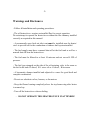
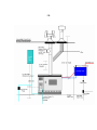
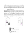
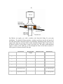
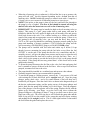
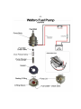
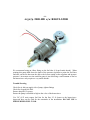
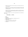
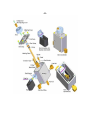
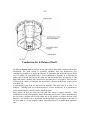
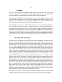
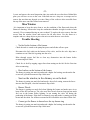
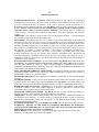
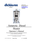
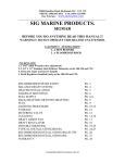
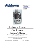
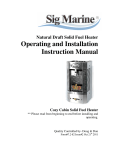
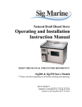
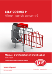
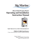
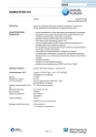
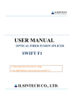
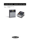
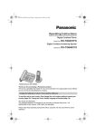
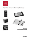
Sig Marine Products
#407-204 Cayer St. Coquitlam
B.C. Canada V3K 5B1
www.sigmarine.com
[email protected]
T: 800 659 9768
Stoves / Heaters
Instruction Manual
MODELS
100, 120, 170, 180 HEATERS & 200 , 250 STOVES
This manual must be read and the requirements carried out
to ensure satisfactory performance.
SIG MARINE RESERVES THE RIGHT TO MAKE CHANGES TO PRODUCTS
OR DOCUMENTS AT ANY TIME
QUALITY INSPECTED BY-
Doug & Don
DATE-
Nov 5/2008
-1-
CONTENTS
Warnings and Disclosures
pg-2
Burner Assembly
pg-20
Installation Diagrams
pg-3
Burner Diagram
pg-21
Clearance Diagram
pg-4
Air & Balanced Draft
pg-21
Location
pg-4
Draft Assist Fan
pg-22
Mounting and Securing
pg-5
Checklist
pg-23
Flue Stack (chimney)
pg-6
Lighting Instructions
pg-24
Barometric Install
pg-6
Operating tips
pg-26
Deck Fittings
pg-7
Flooding Burner
pg-27
Fuel Supply
pg-8
Water Exchanger
pg-27
Fuel Pump Install
pg-8
Exchanger Install
pg-28
Pump Diagrams
pg-10
Burner Cleaning
pg-29
Fuel Overflow
pg-12
Casting Maintenance
pg-31
Fuel Diagram
pg-13
Trouble Shooting
pg-32
Fuel Variations
pg-13
FAQ
pg-33
Fuel Measurement &Adjustment
pg-14
Limited Warranty
pg-34
Valve Info
pg-15
Warranty Form
pg-35
Valve Rebuild
pg-16
Fuel Consumption
pg-17
Valve Diagram
pg-19
Valve Safety Features
pg-20
-2-
Warnings and Disclosures
- Follow all installation and operating procedures.
- The oil heater/stove requires an installed flue for correct operation.
Do not attempt to operate the heater/stove without the flue chimney installed
correctly as required in this manual.
- A permanently open fresh air inlet vent must be installed near the heater/
stove to provide air for the combustion or balance draft system installed.
- The fuel supply must have a manual shut-off at the fuel tank as well as a
manual shut-off near the heater/stove.
- The fuel must be filtered to at least 10 microns and not exceed 4 PSI of
pressure.
- The fuel type stamped on the side of the oil metering valve is the same as
the fuel in the tank. D-diesel, SO- stove oil or #1 diesel , K-kerosene
- A barometric damper installed and adjusted is a must for good draft and
complete combustion.
- Do not use substitute valves, burners, or fan motors
- Keep the flames burning completely above the top burner ring after heater
is warmed up.
- Turn off the heater/stove when refueling.
- DO NOT OPERATE THIS HEATER/STOVE UNATTENDED !
-3-
Installation Diagram
NOTE: Not all installations will require balanced draft, a pump, gravity tank, or elbows.
-3B-
-4-
Clearance Diagram
Installation Guidelines
Location
The location of the heater/stove must be large enough to provide safety clearances.
Objects and materials closer to the heater than 6” must be lined with high density, heat
retardant insulation and covered with metal (stainless steel, aluminum, etc.). Another
alternative is using ceramic tiles. Particular care must be taken to protect the surfaces
close to the first section of flue pipe.
The install location should also take into account the length and configuration of the flue
stack. It is generally preferable that the flue stack be a long straight run. If you have the
option, avoid having to use elbows. Consider installing a balanced draft see pg-21.
-5Ideally, the heater/stove should face the bow or stern of the vessel, particularly on a
sailboat. Fuel gravity feeds from the oil-metering valve into the burner. Should this valve
drop below the level of the burner, fuel will not flow uphill into the burner and the fire
will go out. In a beam-facing sailboat installation, the oil metering valve may have to be
relocated to the side of the heater. There are holes on the side to hold the repositioned
valve bracket. If you have any doubt regarding the need for a valve bracket, please ask
your dealer or email [email protected]
Mounting and Securing
Model 180 heater holes have been provided in the feet to allow appropriate fasteners to
secure. The drip tray will then slide under the bottom of the heater.
Model 200 & 250 unscrew the acorn nuts on the front bottom panel. Unclip the speed
control wires. Secure the tie-down bar (supplied) to the floor 2 ins from the back of the
area where the stove will sit. The raised ends of the bar must be up, to allow the side
flanges (“feet”) of your stove to slide underneath. This will allow the stove to be slid
forward for service and cleaning while also securing it firmly to the boat.
The stove must be leveled and secured at the front through the bolt holes at the base of
the side panels. Use the fastener appropriate for the material of the floor where the stove
is to be secured. The finishing tray (supplied) will slide under the stove.
Model 100 to 170 use appropriate hardware to secure the heater to insulated area.
-6-
Flue Stack
The length and straightness of the flue stack are important to the efficient operation of the
heater/stove. The Flue stack must be the correct diameter. If elbows must be used, the
elbows shall not be greater than a 45 degree angle. The first elbow should not be closer
than 12” (28cm) to the heater/stove. Allow for as much straight pipe as possible before
the first elbow. The stove pipe will attach to the stove by squeezing the round pipe
over the oval flue collar when installing.
A Barometric Damper is a MUST FOR BEST COMBUSTION.
The barometric damper should be installed in oil and solid fuel heaters and stoves. The
purpose is to maintain a strong draft without causing too much air to the fuel mixture.
When the damper is adjusted the draft is altered by allowing air to be pulled into the
chimney by the air inlet on the damper and not pulled into the primary mixing holes in
the burner.
Install the barometric tee pipe with the front flap facing fore and aft.
In order for the barometric to work efficiently it must be installed between 12” and 24”
from the heater/stove exhaust collar. If using a pipe guard turn the barometric tee to the
back as it does not have to be seen to work.
To adjust the flap on the barometric back off the jam nut and turn the counterweight so
the flap is standing closed. The valve must be set to flow 1 teaspoon per the amount of
seconds as per the list of fuel flow measurements on page 12, and on the #1 lowest
setting. Once the heater/stove has been burning for some time and the room temperature
is starting to rise is a good time to do the adjustment.
Adjust the counterweight so the flap starts to open (aprox 6mm or ¼”). This will allow air
to enter the barometric tee and reduce the air entering the burner. This will cause the
flame to burn above the top burner ring. If the flame is still burning below the ring adjust
the flap open another 3mm or 1/8”. At this time if there is flame burning below the top
burner ring and the barometric flap is open aprox 9mm or 3/8” do not adjust the flap open
any further and re-adjust the valve fuel flow rate until the flame is above the ring.
This adjustment need only done once after the install and the jam nut can be re-tightened.
The draft above the top of the fire will be aprox -.05 inches of water column, should you
have a draft meter, however adjusting the damper as above should get you close enough.
-7-
Sig Marine can supply you with a stainless steel thru-deck fitting for your pipe
installation. The thru-deck fitting includes a stainless steel dress ring for the interior of
the cabin and a rubber (neoprene) gasket easy mounting. Depending on the contour or the
angle of the cabin top, you may need to make a hardwood spacer block. One surface of
the block would be a level plane to mate to the deck cap. The other would match the
angle or contour of the cabin top. A hole through the center of the block would be 2
inches greater in diameter than the flue pipe.
Flue Diameter
Recommended
Length
Minimum Length
Hole Diameter
Sig 100
3” (7.62cm)
6 ft (1.83m)
3 ft (0.92M)
5” (12.7cm)
Sig 120
3” (7.62cm)
6 ft (1.83m)
3 ft (0.92M)
5” (12.7cm)
Sig 170
3” (7.62cm)
6 ft (1.83m)
4 ft (1.23m)
5” (12.7cm)
Sig 180
3” (7.62cm)
6 ft (1.83m)
4 ft (1.23m)
5” (12.7cm)
Sig 200
4” Standard (10.16cm)
5” Optional (12.7cm)
6 ft (1.83m)
4 ft (1.23m)
6” (10.16cm) Standard
7” (17.78cm) Optional
Sig 250
4” Standard (10.16cm)
5” Optional (12.7cm)
6 ft (1.83m)
4 ft (1.23m)
6” (10.16cm) Standard
7” (17.78cm) Optional
-8The H style flue caps are recommended, especially if the balanced draft system is not
used. The location of the flue cap above deck must be clear of any immediate obstruction
that may cause unusual air movement or turbulence. CAUTION : The Flue Cap gets hot
when the stove is operating.
Note: The caps, pipe, and deck fitting may appear to have a rusting look. This is caused
by operating the heater too rich. This will produce soot that will leave carbon deposits on
the stainless steel giving the appearance of rust, much like cleaning stainless steel with a
steel SOS pad. The stainless can be cleaned with a scotchbrite pad to remove the rusty
looking surface.
Fuel Supply
Fuel is supplied to the oil-metering valve of the heater/stove from a gravity feed tank or by a
low-pressure pump direct from the main fuel tank. The fuel metering valve is rated to an
incoming fuel pressure of 3 psi. If fuel supply exceeds 4 psi a pressure regulator will be
needed in the supply line.
Install a gravity tank no higher than 8 feet above the valve of the heater without a
pressure regulator.
Install a low pressure fuel pump with a pressure no greater than 4 psi (2.5-3 psi is
ideal)
Install a low pressure fuel regulator set to within a range of 2.5-4 psi. When a gravity
tank is used a minimum head of fuel 12" (30.48 cm) above the fuel level marked on the
side of the oil-metering valve is required to operate the oil-metering valve. The gravity
feed tank must be vented and all fuel lines must be as straight as possible to avoid air
locks. The fuel inlet is a 1/8 npt female thread .
#15078 FRD-2
3 PSI FUEL PUMP
&
#15079 FRD-HD c/w REGULATOR FUEL PUMP
•
•
•
These are 12 volt DC pumps. The factory spring pressure for the #15078 FRD-2
pump is set at 3 PSI (max 6 ft. lift).
The #15079 FRD-HD pump has a stronger pressure spring that will draw the fuel
higher (max 15 ft. lift) but will need the regulator to adjust the pressure down to 3
PSI before the fuel goes to the oil metering valve.
You must use a fuel oil filter in your installation before the pump to keep debri
from plugging up the 3 check valves inside the pump.
•
•
•
•
•
•
•
•
-9When the oil metering valve (carburetor) is full and the line is up to pressure, the
pump will still “tick” but less frequent depending on the demand from the oil
metering valve. NOTE: Include the pump in a control circuit with a 3 amp fuse )
(16 awg wire) so you can turn it off when the heater/stove is not in use.
NOTE: If the power to the pump is shut off, the fuel could still flow through to
the pump by way of siphon. The flow of fuel should be turned off using the
shut-off valve near the heater/stove as well as the oil metering valve.
IMPORTANT! This pump must be installed as high as the oil metering valve (or
higher). This pump is a “pull” pump rather than a push pump, and must be
installed so that the fuel oil is pulled as high as the oil metering valve and gravity
feeds back down to the valve. Use a rubber backing as a washer to soften the
sound of the pump and use appropriate screws to mount the pump.. If there is no
fuel getting to the oil metering valve, you may need the heavy duty pump #
15079, or call / email Sig Marine for retrofitting a stronger pressure spring in your
pump and installing a pressure regulator # 15074 between the pump and the
valve(converting a #20-000 FRD-2 pump to a #20-002 FRD-HD pump).
The pumps can be installed with fuel inlets and outlets up or down (1/8 npt
thread), however mounting the pump with the fuel inlet on top (Note the fuel
OUTLET is on the end of the pump that has the wire connections and the 3
assembly screws), will give the pump extra pressure and is easier to clean but will
need to be primed the first time only to remove air in the fuel line). There are 3
check valves in the pump to prevent the back flow of fuel, so the pump should
stay primed. If the pump does not stay primed then 1 of the check valves in the
pump needs cleaning.
To prime the pump disconnect the fuel line at the valve fuel inlet and pump fuel
into a container to remove all the air in the fuel lines. After a cup of fuel has been
pumped, reconnect fuel line to the valve.
The pump should be installed in a ventilated area and not near a hot exhaust.
Ground to negative battery (not recommended for gasoline).
To retrofit the pump to a higher pressure unscrew the 3 torx screws (t-20) and
with twisting the lid back and forth, pull it straight back off. Note the pump
plunger, spring, check valve , and a very small amount of fuel will drop out if
installed as per diagram. Place the check valve as shown in the diagram on top of
the heavier replacement spring, and the spring on top of the pump plunger and
push it back into the pump body holding it in with a finger. Note the magnetic
part of the plunger is on the opposite end of the spring. Replace the lid with the
gasket on by lowering your finger on to the red O ring sleeve without the
plunger falling out ( the plunger is about 2” long so you have room to lower your
finger out of the way). The red O ring sleeve will fit inside the pump tube and the
black O ring will fit over the outside of the pump tube and will require twisting
and pushing the lid straight back in. This is a little tight but that is what makes
the seal. Rotate the gasket and replace the screws.
-10-
-11-
#15079 FRD-HD c/w REGULATOR
We recommend using an elbow fitting on the fuel inlet (1/8 npt female thread). When
priming this pump hold down the knob of the pressure regulator to prime the fuel lines
and take out the air then turn the dial to the lowest setting on the regulator and increase
pressure 1 increment at a time until the pump is just delivering a small amount of fuel as
the heater/stove only requires a very small amount .
Trouble Shooting
Check for air leak on supply side of pump, tighten fittings
Check for clogged fuel filter
Ensure adequate 12v power
Ensure the pump is installed as high as the valve of the heater/stove
Use 3/8" (9.52 mm) copper fuel line for the first 2-3 ft closest to the heater/stove.
Approved hose can be used for the remainder of the installation. DO NOT USE A
PRESSURIZED FUEL TANK.
-12When a low pressure fuel delivery pump is used (less than 4 psi) a fuel line must be
plumbed directly from the main fuel tank or tee in at the tank (not from the engine supply
line or engine filter). Use a check valve in the heater fuel line to stop the engine from
pulling back the fuel and starving the heater/stove. The fuel inlet is a 1/8 npt thread . To
keep the oil metering valve clean and trouble free install a fuel filter to remove impurities
from the fuel. If you use a fuel pump, we suggest having the filter before the pump. We
suggest changing or cleaning your filter or filter element each year.
A fuel shut off valve must be installed as a positive shut off control for the fuel supply.
We suggest this be installed in the same area that the heater/stove is being used. Provide a
fuel filter/shut off valve with a replaceable stone element.
Metering Valve Overflow
The overflow feature of the oil metering valve is designed to allow the controlled escape
of fuel from the heater/stove in case of over pressurization. If dirt, debri, or too much
pressure gets into the needle and seat inside the valve the fuel will rise then overflow out
of the valve and away from the heater/stove. It is common to get a few drips now and
then from the movement in rough waters however fuel from the overflow indicates the
need to service and clean the valve float and needle and seat.
Under no circumstances must the overflow fitting be plugged. A fuel line must be
taken from the overflow fitting (1/8 npt thread) back to the main tank or to a container
away from the heat source.
The fuel overflow is a gravity escape. Do not install the overflow line so that is goes up
or loops as this will cause an air lock and block the fuel from escaping. Install a
container, if used, lower and away from the heat of the heater/stove.
NOTE – If the vent of the boats fuel tanks are higher than the valve of the heater, and the
overflow of the heater goes back to the tank, there may be a chance that the fuel (when
refilling) will back flow up the overflow and out of the valve. If your installation is
similar you may need to install a manual shut-off teed in the overflow line and closed
when refilling tanks. CAUTION After refilling re-open the shut-off valve. Do not use a
check valve.
-13-
Fuel Variations
It is unlikely that the fuel you are using is the same viscosity as the fuel used to calibrate
the oil-metering valve. Diesel is one of the few fuels you can reliably get all around the
world but the quality and viscosity of that fuel is variable. Fuel differs on a routine basis
even though you buy the same oil from the same supplier. Factors influencing oil
viscosity include: the temperature; the age and quality of the fuel; the regional differences
due to local refineries; and the particular mix of certain brands of fuel. The oil metering
valve is calibrated for #2 diesel (unless requested otherwise). Burning diesel #1 (stove
oil) will allow 25% more fuel and burning kerosene will allow 50% more fuel to flow
through the oil-metering valve. Because of this, it is important to burn the fuel for which
the heater has been calibrated. Metering valves are available for diesel (D stamp on
valve), kerosene (K stamp) or stove oil, (SO). By Studying the burning characteristics it
can be determined whether the fire is too high or too low.
-14It is important to know that although you can re-calibrate your valve to each variation of
fuel, you can also adjust the way you operate the heater/stove to compensate for these
variations. If the oil is thicker than usual, open the valve more or use less fan. If the fuel
is thin, run the fan more to burn off the fuel.
Fuel Flow Measurement
If your heater/stove is burning rich (making soot or smoking) or burning lean (flames not
burning above the top burner ring), adjust the flow as follows regardless of what type of
fuel:
1) Unscrew the nut from the bottom of the valve and bend away the copper fuel
line. Allow the oil to drip into a cup or container.
2) Turn the valve knob to the #1 setting. Measure the quantity of oil dripping
slowly from the fuel outlet.
Knob Setting 1 (model 100 & 120) 1 teaspoon in 105 seconds (2.5 c.c.'s / minute)
Model 170 & 180
1 teaspoon in 90 seconds (3 c.c.'s / minute)
Model 200 & 250
1 teaspoon in 75 seconds (3.5 c.c.'s / minute)
-15-
Fuel Flow Adjustment
Refer to the Oil Metering Valve diagram. The height of the valve-adjusting knob will
determine the quantity of oil exiting from the valve outlet. The height is determined by
the length of the metering screw against the fuel ramp on the main casting of the valve.
Adjust the set screw located in the center of the brass nut on top of the knob (turn
counterclockwise to increase). Adjust 1/8 turn at a time.
Oil Metering Valve
Information and rebuild instructions.
#905005
Do not plug the overflow fitting. A fuel line must be taken from the overflow fitting and
returned to the main tanks or to a vented container.
The overflow line is a gravity escape and must be installed in such a manner as to prevent
air locks. The line may need priming so as to ensure the fuel will escape in the case of a
malfunction in the fuel delivery.
NOTE: The valve code and fuel identification are stamped on the valve body adjacent to
the overflow outlet. See the chart below for your valve identification.
NOTE: In some areas oil is thicker than normal. This is common in areas where the oil is
under processed or where the temperature is very low. In such cases, valves with larger
stem grooves are used. For example, a 3D may be used in place of a 2D.
NOTE: Stove Oil (diesel #1) has become a variable product over the years. The viscosity
and composition can vary from area to area. Please keep this in mind if Stove Oil is your
fuel of choice.
-16Model / Fuel Type
Diesel
Kerosene
Stove Oil
100
120
1D
1D
1K
1K
1S
1S
170
180
2D
2D
2K
2K
2S
2S
200
250
3D
3D
3K
3K
3S
3S
NOTE: Bio-Diesel: Due to the higher vaporization temperatures of bio-diesel and the
variability in composition and viscosity the setting on the valve will constantly change.
Example: With one type of bio-diesel the heater/stove burns best on #2 setting then
burning the heater/stove with another grade will change the setting so the heater/stove
burns best on #1 or #3 setting. This is also true with regular diesel but more noticeable
with bio-diesel. The same goes for low carbon (sulfur) diesel.
Fuel Consumption
Turning the knob of the oil metering valve counter clockwise increases the quantity of oil
entering the burner, and all valves have been calibrated and tested at 3 p.s.i.
Fuel Flow Rates
Code
1D
2D
3D
Low
2.5cc/min (.75 imp Gal/24 hrs)
3.0cc/min (.9 imp Gal/24 hrs)
3.5cc/min (1 imp Gal/24 hrs)
High
6.0cc/min (1.8 imp Gal/24 hrs)
8.0cc/min (2.4 imp Gal/24 hrs)
9.5cc/min (2.7 imp Gal/24 hrs)
Valve Rebuild
Detach copper fuel lines from the valve inlet and outlet and overflow, then remove the
valve from the mounting bracket (do not remove the overflow fitting from the valve).
Unscrew the 4 retaining screws holding the valve top to the body. Note that the valve top
and the valve knob are attached.
-17-
Variations
The valve rebuild kit #905005 has been packed with all the parts to rebuild your valve.
The parts may differ in detail from what you have in your valve. This is due to changes
and to the unavailability to the parts over the decades. These parts provided in this kit
will work in most Sig Marine valves.
•
•
•
•
•
•
•
•
•
•
•
•
•
Remove the float from the bottom casting
Remove the needle from the seat fitting.
Using a 5/16ths socket, remove the seat fitting from the valve bottom casting,
however leave the copper washer in.
Remove the fuel inlet fitting only and remove the stainless screen behind the inlet
fitting.
Clean the threaded aperture in the bottom casting to remove any dirt or buildup.
Perhaps use a pipe cleaner to clean the path from the inlet hole to the seat fitting
aperture.
Remove and replace with viton ‘o’ ring on the valve stem, and clean the stem
groove.
Clean out the stem guide in the bottom of the valve housing and the overflow
tube.
Clean the inside of the valve housing castings, top and bottom.
Replace oil inlet screen with new and replace the inlet fitting into the bottom
casting (use teflon tape and do not over tighten).
Place the small adaptor in over the copper washer and place the new copper/brass
washer over the adaptor, then screw in the new seat into the bottom casting until
tight but not so tight as to damage the aluminum threads of the casting (35 inch
pounds).
Place the new needle in the groove of the float and insert the float pin through the
bracket and float, then snug up the float screw.
Loosen the float screw so the bracket will move up and down and adjust the
bracket so when pushing on the needle the top of the float will be parallel with the
top of the casting. It is very important to keep the float from binding on the stem
guide as it moves up and down. If the float is not parallel to the casting , the float
pin tabs on the float will need adjusting. Hold the float firmly and bend the tabs
using needle nose pliers being gentle to not break the float from the tabs (a small
crack is acceptable). Bend both tabs down, or both up to keep float level parallel
being careful not to put pressure on the needle and seat when making the
adjustments. Check the float for sitting perfectly straight as you may need to bend
one tab up and the other tab down in order to achieve the top of the float straight
in both directions.
-18•
Replace the top casting into the bottom casting so the metering stem slides in to
the metering guide.
•
Replace the 4 top screws snugly, and move the control knob up and down while
tightening the 4 screws. Once tight the control knob should move up and down
freely in any position.
•
Meter the valve to the specifications above and check the overflow fuel line ( if
the float is operating correctly and adjusted parallel to the casting the oil level in
the valve will be correct.
The metering screw/high fire screw can also be replaced from the valve rebuild kit, or
kept as a spare.
Kit Includes (# 905005)
1.
2.
3.
4.
5.
6.
7.
8.
9.
Float
Float pin
Float Bracket
High Temp Fuse c/w metering screw adjustment screw (6-32)
Replacement fuel screen
Viton ‘O’ ring
Needle & seat & copper/brass washer assembly
Adaptor spacer for new style needle and seat
Instructions
-19-
-20-
Valve Safety Features
A Flame out relates to the oil level and the float level in the oil metering valve. In the
event that the heater flame is blown out, oil will continue to accumulate into your burner
pot to the depth of 9/16 inches and no more. This oil must be removed from the pot
before the heater is lit again or the heater will dangerously overheat.
A high temperature fuse is incorporated into the oil metering valve. The adjusting screw
on the knob of the oil metering valve is fitted with a fusible sleeve. This fuse will melt if
the valve knob reaches a temperature of 165 degrees F. This will shut-off the flow of oil
into the burner. . Under normal conditions the valve is at room temperature. If the high
fire sleeve melts it indicates too much heat in the burner. Overheating of this kind is due
to incorrect operating procedures (the flames are burning down in the burner pot) and
should be rectified before an overheat occurs again. In case of the release of the fusible
link, a replacement part is available from Sig Marine or just remove the brass nut (do not
move the adjusting screw) and apply heat from a lighter to re-solder the link back into its
original position (flat on the top). Once back in place the adjusting screw will not need
re-adjusting.
DO NOT ALLOW FLAMES TO BURN BELOW TOP RING.
DO NOT LEAVE YOUR HEATER BURNING UNATTENDED
Burner Assembly
Your diesel heater/stove has been equipped with a 4.5” or 5.5” Sig burner. There are
two components in the burner that must be correctly placed for the heater/stove to operate
properly. The burner ring must be placed at the top of the pot so the outside edge of the
ring fits into the groove in the top of the pot. Ensure that the ring fits in evenly and snugly
all the way around the pot and that all of the oval shaped slots are clearly visible.
The second component is the superheater. The superheater is placed through the burner
ring and will sit on the bottom of the burner with the round 2” disc sitting 2” up from the
bottom of the burner . The flat legs on the bottom of the superheater should sit flat on the
bottom of the burner to radiate heat to the fuel coming in through the center of the
superheater . This will need to be kept clean to allow fuel to flow through it. The upper
legs of the superheater will sit up above the burner ring where the flames are and radiate
heat down to the vaporizing fuel.
The 2” round disc sitting 2” above the bottom of the burner is to deflect the hot rising
vapor up the sides of the burner pulling in the primary air needed to mix with the fuel.
-21-
Combustion Air & Balanced Draft
Sig Marine heaters only are unique in that they can be fitted with a balanced draft flue
installation. The draft system is, generally speaking, how the heater/stove gets
combustion air and how it expels the exhaust. To guarantee that sufficient oxygen (fresh
air) is available for your heater/stove, good ventilation is essential. It is necessary to
replace the air inside your boat at the same rate that the heater/stove is removing it. The
higher the heater’s burning rate, the more air the heater/stove will require. If the air flow
is blocked (the ‘draft’) or restricted, the heater/stove will burn inefficiently, create soot or
even blow out.
A permanently open fresh air inlet must be installed. This inlet must be at least 3" in
diameter. Ducting fresh air to the heater/stove is most satisfactory. It is important to
create and maintain a positive pressure inside the boat.
High winds can draw air from the boat and thus create a negative pressure. This
condition can result in down drafts. Ensure that when you do have widows open that they
do not create a suction effect in the cabin due to the window’s position and the wind
direction. In a similar way, it is possible for the air intake on your engine to suck the air
out of a cabin if it is not properly vented. Your heater/stove is a natural draft appliance
and
-22creates its draft pressure like a chimney in a wood stove. The rising, heated air in the
stack pulls fresh air into the heater/stove as it rises up the stack and exits the flue cap. The
greater the draft pressure the more able the heater/stove will be to resist strong winds,
overcome flue elbows (that inhibit draft) and the hotter you will be able to get your
heater/stove without sooting. A CO alarm should be installed in the boat along with the
Sig Marine (appropriate diameter) high heat shut-off , if you are unable to fully attend
the heater/stove and still be on board the boat.
If when lighting the heater/stove, the smoke from the burning tissue is sucked up the
chimney then the boat has a positive pressure (good draft), but if the smoke comes out of
the heater/stove before closing the door or replacing the lid then the boat has a negative
pressure. Air is drawn in by way of the chimney instead of a vent and will have to be
corrected in order for the heater/stove to have a good draft and operate correctly. For this
reason you may decide to install the heater using balanced draft. This is taking the vent
and attaching it directly to the heater and connecting the other end of the vent to a deck
fitting air intake so the heater is not effected by the air in the boat. This will require
special attention to the install and the purchase of the deck air intake fitting and a rain cap
along with stainless steel piping, or solid plastic pipe, or even flex tubing, depending on
how cosmetic the install will look.
Draft Assist Fan
During start up, at higher settings or during windy conditions, you may want to use the
combustion assist fan on your heater/stove to artificially boost the draft. Your heater/stove
should operate without the use of the fan but it is convenient during start up and some
heater/stove installations are accomplished with only the minimum flue heights or with flue
elbows that can inhibit the draft. Due to these possibilities, the combustion assist fan will
balance the fuel to air mixture.
1 To speed start-up and pre-heating.
2 To ensure complete combustion and avoid flooding the burner when the fuel supply is
turned up too quickly.
3 To limit the effects of back draft should this occur during windy conditions.
4 To operate the heater/stove at high fire settings without carboning or smoking.
NOTE: Operating the fan can deliver too much air and cause the burner to run too lean
(too much air in the fuel to air mixture). When using the fan try to give as much air as
possible until some of the flames drop down and burn below the top burner ring, then
back it off slowly until all the flames are again burning above the burner ring.
-22A-
-23Installation Check-List for a Natural Draft Oil Heater / Stove
A permanent 3” dia. fresh air vent to provide your heater/stove with the air it needs
to operate properly.
Have a minimum of 4 feet of exhaust stack.
The first 12” of exhaust pipe from the heater/stove is going straight up without any
elbows.
Install a barometric damper between 12” and 24” from the top of the heater/stove.
The overflow return from the valve is going to an overflow container or back to
the main tank.
If using a gravity-feed tank it has to be a minimum of 12” to a maximum of 8 ft.
above the oil level of the valve unless you are using a fuel pressure regulator.
If using a fuel-pump at 4 psi to pump oil from the main tank we recommend
mounting it at the same height as the oil level in the valve.
Check all fuel line connections for any leaks.
There is a 2” space around the heater/stove and 6” away from any combustibles.
Insulate the wall or objects around the heater/stove with at least ¼” insulation and a
sheet of stainless steel on ½” standoffs or ¼” insulation with ceramic tile.
Installs in sailboats has the valve in line with the boats keel.
The exhaust cap is clear of any obstructions to create unusual air movement.
The fuel tank is not pressurized.
If running fuel from the main tank, the tee into the fuel line is right at the tank
before the filter.
There is a fuel filter installed
A fuel shut-off valve is installed in the same area as the stove.
All protective plastic on the stainless steel must be removed before lighting.
-24-
Lighting Instructions
1.
ENGAGE PUMP OR OPEN GRAVITY FEED VALVE TO ALLOW FUEL INTO THE
METERING VALVE ON THE HEATER.
2.
OPEN THE DOOR OR LIFT LID AND REMOVE THE RING & SUPERHEATER
3.
TURN THE OIL METERING VALVE ON UNTIL APPROX 30 ml (2 tblsp) OF OIL HAS
COLLECTED IN THE BOTTOM OF THE BURNER POT
4.
TURN THE OIL METERING VALVE OFF
5.
LIGHT THE POOL OF FUEL WITH A SMALL TWISTED PIECE OF TISSUE OR PAPER
TOWEL
6.
WHEN THE LIT PAPER HAS IGNITED THE OIL, REPLACE THE RING &
SUPERHEATER INTO THE BURNER AND CLOSE THE DOOR OR REPLACE THE LID.
7.
OPEN MANUAL DAMPER OR TURN ON THE COMBUSTION ASSIST FAN TO MEDIUM
LOW
8.
THE PRIMING FUEL WILL BURN FOR APPROXIMATELY 5 MINS. AND THE FLAME
WILL REACH THE TOP OF THE BURNER POT AND THEN, AS THE HEATER STARTS
TO GO OUT, THE FLAME WILL DROP BACK IN THE POT.
9.
WHEN YOU SEE THE FLAME ALMOST ABOUT TO GO OUT, TURN THE OIL
METERING VALVE TO POSITION ONE AND WATCH THE FLAME RISE UP TO THE
BURNER RING.
10. IF THE FLAME GOES OUT FOR ANY REASON AT THIS STAGE, TURN THE VALVE
OFF AND WAIT 5-10 MINUTES TO COOL THE BURNER BEFORE TURNING VALVE
BACK ON AND RE-LIGHTING THE BURNER. DANGER NEVER LIGHT A HEATED
BURNER
11. WHEN THE HEATER/STOVE AND FLUE PIPE ARE HOT (20 MINS) THE COMBUSTION
FAN MAY BE TURNED OFF OR TURNED DOWN OR THE MANUAL DAMPER MAY BE
ADJUSTED TO SLOW DOWN THE AIR OR ADD FUEL. (SLOW FUEL INCREASES).
THE FLAMES MUST BURN COMPLETELY ABOVE THE RING.
12. AFTER 30 MINS, YOU MAY WANT TO INCREASE THE HEATER/STOVE SETTINGS.
MAKE VERY SMALL INCREASES ( ½ TO 1 ) INCREMENT AT A TIME, 5 MINUITES
APART.
CAUTION: NEVER LIGHT A FLOODED BURNER. NEVER LIGHT A HEATED BURNER
TO AVOID UNINTENDED COMBUSTION OF FUEL VAPOUR
NOTE: You can deviate from the #2 lighting instruction by leaving the
superheater in, then on #5 instruction you will need to use the auger tool to
push the lighted tissue off the superheater disc into the fuel below.
-25The first time the oil-metering valve is turned on it will take 5-10 minutes for the fuel
lines to fill and oil to appear in the bottom of the burner. In the beginning you will want
to see approximately 2 tablespoons of oil accumulate in the bottom of the pot before
lighting. You will soon come to know how long the valve should be open to accomplish
this. The burning characteristics of the flame during lighting is as follows
After start up and after a couple of minutes have passed, the flame should be lemon
yellow, perhaps with some blue. Dirty orange colors or visible soot or smoke indicate an
inefficient burn. The fan should be turned on to add more air in this situation or the FUEL
DECREASED .
The flames should also be entirely burning above the top burner ring. Flame beneath the
burner ring indicates an inefficient burn and will contribute to carbon build-up. The fan
should be turned off or down or adjust the barometric damper open in this situation or the
FUEL INCREASED.
Warnings
Do not light a hot burner
Do not light a flooded burner
Do not use gasoline or other highly flammable material to light the burner.
-26-
Operating Tips
Every time the position of the knob on the oil metering valve is moved (fuel), the air will
need adjusting in order to have the correct fuel to air mixture. This will:
1 Keep the burner, combustion chamber, flue pipe, and your deck clean
2 Keep the draft strong against down drafts
3 Keep the correct heat in the correct part of the combustion chamber
On the lower settings the burner needs less air. To reduce the air, adjust the barometric
damper open wider (pg-6), turn down or turn off the fan, and add more fuel even if you
do not want the heat. It is better to make too much heat and dissipate it than to run the
burner too lean (flames in the burner) as this will result in hard carbon build up and soot.
The burner was designed to burn a certain amount of fuel on low and if less fuel is burned
(flames below the ring), the burner will not burn clean.
Turning up the valve in small increments will help the draft catch up with the fuel
increases, and this keeps a good fuel to air mixture, and that helps in reducing soot.
When on medium to higher settings when the flames are looking orange with black tips,
turn the fan on, but use the lowest fan speeds and increase air slowly until the flames
start to turn yellow and are more vibrant. If you turn the fan on too much air will burn off
all the fuel and the flames will end up below the top burner ring. If you do not have a fan
the fuel increases will have to be done at slower increments.
After the heater/stove is well heated and cabin temperature is reaching comfort, the valve
body and the fuel in it will start to warm and the heater/stove will start to burn hotter. An
adjustment will have to be made to turn down the fuel to the lowest setting so that the
burner will have all the flames above the ring and not the setting on the valve. The
number will only be used as a reference so you now know how low you can go and still
have a clean burn. This is very noticeable when the fuel is in a very cold temperature.
When using the fan keep in mind that low settings require little or no air.
On the medium settings very little air or still none depending on if you have a longer
chimney. The higher settings need air to keep the flames yellow but as the heater gets
hotter the fan air can be reduced as the chimney will start to pull more air on its own.
With no fan the highest setting may be too rich and a higher chimney will be required or
fuel setting has to be reduced.
While lighting the burner you can leave the superheater in the heater, give it a twist back
and forth to clear the oil inlet, then throw the lighted tissue in. The tissue will land on the
-27disc that is 2” above the bottom of the burner and will need to be pushed into the fuel
underneath. The auger that came with the heater is a good tool for this and keeps your
hands cleaner.
Flooding Burner
A vaporizing oil burner of this type can be flooded if care is not taken to prevent excess oil
entering the burner when lighting. By following the lighting instructions flooding will be
avoided. A flooded burner that is still burning should be turned off and the heater monitored
until the oil has burned off. Use the combustion assist fan to add air to fully combust the
excess fuel. Causes of burner flooding:
Fuel entering the burner faster than it is burning.
Increasing the fuel supply too quickly without use of the combustion assist fan.
Poor draft and/or ventilation.
If the flame has extinguished, the oil metering will continue to deliver fuel to the burner
causing it to accumulate fuel to a level of 9/16”. Never relight this amount of fuel.
The suggested method is to sacrifice a toilet paper roll as a perfectly fitted sponge and
then dispose the roll. For this reason always monitor the heater closely when lighting.
Hot Water Heat Exchanger Option
The stoves and model 180 heater can be equipped with a small or large heat exchanger.
This optional item should be installed at time of manufacture but can be retrofitted later.
Specifications Coil 5/8th ins O.D. stainless steel tubing
Small exchanger10-15 gallon tank
Large exchanger-
15-20 gallon tank
-28The exchanger in a heater/stove can be used to heat the water in your existing hot water
supply tank. If the tank is mounted above the lower coil the water will circulate on its
own from the tank into the hot coils and rise back into the tank. If the large exchanger is
used on smaller tanks, it will make the water too hot and the pressure/temperature relief
valve will release too often. In this case the hot supply line will need a cooling radiator to
dissipate the extra heat. A radiator core will take the extra heat out of the water and return
the heat back into the cabin. If a small exchanger is used with a larger tank the recovery
time may take a long time. The temperature of the water will change from the operating
settings set on the heater. When the exchangers are used in a hydronic system the
temperature of the water will vary from the speed of the water being circulated through
the system.
Exchanger Installation
It is best to order the heater/stove with the exchanger installed, but follow these
instructions for replacing or installing a new coil.
1. There are 2 knockouts on the back of the heater/stove( no knockouts on the model
180) that will need to be removed.
2. Use a screw driver and hammer to wedge the knockout open, then use pliers and twist
the knockout until it breaks off.
3. The exchanger should fit through the lid hole to manipulate the coil so the ends of the
coil stick 2” out from the wall of the stove.
4. Drill a hole and position the bracket that was included with the coil, to hold the coil in
place with a 1/8th drill bit. Use the #10 x 1 1/4" screw to screw down the 'L' shaped
bracket. Clamp down the coil between the two bracket pieces. This bracket keeps the coil
in place. It is important that the coil be installed so there is a constant rise in the tube as it
goes to the back of the stove. This aids in the movement of the water or glycol.
-29-
Cleaning Stove Burner
Carbon accumulates in the burner over a period of time and it must be cleaned out. It is
especially important to ensure the air holes are clear. If you are burning good quality fuel
and the heater is burning efficiently this cleaning procedure will only be required once a
year. If there is rapid carbon build up in the burner pot, it indicates an operation problem
or the need for a barometric damper adjustment. If you do not have a barometric you
should install one to reduce the air in the burner that is causing the carbon build up. This
must be rectified for satisfactory operation of the heater.
1)
Remove the lid.
2)
Insert the reamer tool (provided) into the fuel inlet hole. This will prevent loose carbon
falling into the fuel inlet during cleaning.
3)
With a wire brush, scrape any loose carbon from the sides of the burner.
4)
Using a paper clip poke out the four rows of air intake holes on the sides of the burner to
ensure that they are clear.
5)
Remove any loose carbon from the base of the burner.
6)
Remove the reamer and replace the burner ring and superheater.
Cleaning Heater Burner
Depending on the quality of the fuel that you use and how often you use the heater, some
carbon may build up around the legs of the superheater and on the inside of the burner. You
may clean the burner by reaching in through the door or by removing the burner:
--Disconnect the fuel feed and the over-flow lines
--Remove screws “ A”, one on each side of the stainless housing
and loosen the screw “B” on the right side of the combustion
chamber under the door with the window. The burner will now
drop out.
1. To clean the burner, first take out the burner ring and the
superheater. Next place a pan under the burner to catch the fuel
when you remove the 1/4” clean out plug in the bottom of the
burner. Then clean out any carbon pieces in the burner. You
may have to use a scraper to remove the build up of carbon. The base of the burner
should be free of any carbon so that the four feet of the superheater make “metal to
metal” contact with the base of the burner. Any carbon will act as an insulator and you
will not get a good heat transfer from the superheater to the base of the burner.
-302. Next, use the auger supplied with the heater to ream out the burner oil inlet hole in the base
of the burner. Later after the burner is reinstalled and before you replace the 1/4” clean out
plug, flush out the system by turning on the metering valve (carburetor) and letting some fuel
drip out the bottom.
3. There are four rows of holes in the side of the burner. These must all be clean. Use an
unbent paperclip (or the like )can also work. “Never! Never! Never! Enlarge or alter these
holes. Do not use a rag to wipe the inside of the burner, because you will be pushing carbon
into these holes. If needed, use a wire brush. Now replace the 1/4” clean out plug, be sure to
use some sealer and don’t over tighten. Replace the superheater. Be sure all four feet are flat
on the bottom of the burner base. Replace the burner ring. Note that the correct way is with the
disk down. Reconnect the fuel feed and overflow lines.
Cleaning Fuel Lines
Any blockage in the fuel line from the oil-metering valve to the burner can be cleaned by
removing the clean-out plug situated directly under the burner. The plug must be replaced
with tape sealant and checked for leaks. The fuel lines themselves can be cleaned with
compressed air or a pipe cleaner to remove any blockages. Tap the fuel line to relieve air
locks.
DO NOT OPERATE THIS PRODUCT UNATTENDED
Lighting Instructions
1.
2.
3.
4.
5.
6.
7.
Remove top lid / open door
Turn the oil metering valve ON and allow about 30 ml (2 tbls) of fuel into the burner.
Turn the oil metering valve OFF
Open oven damper if applicable
Light the fuel with a twisted paper tissue
Replace lid / close door
Turn the fan assist to low speed
NOTE: If the flame should go out at this stage, do NOT relight for 10 minutes.
8. The fuel will vaporize in 5 to 10 minutes and when the flames go down in the burner
and start to go out: Turn the valve ON to a low setting that will keep the flames
burning above the burner ring.
9. When the flue pipe is hot(15 minutes of burning) the assist fan may be turned OFF or
on a very low setting.
10. Stay on low setting for 30 minutes before selecting higher settings
INCREASE FUEL SETTINGS IN VERY SMALL INCREMENTS
CAUTION: NEVER LIGHT A FLOODED BURNER
-31-
Cooking
The top of your stove is your hotplate cooking surface. (Sig 180, 200, and 250) On the
cookstoves, the left side, above the burner, is hotter than the right side. From a cold start it will
take approximately 30 minutes before the top has reached cooking temperatures.
The oven (Sig 200, 250) can only be used when the stove is thoroughly pre-heated. This
normally takes 40-50 minutes. At low fire oven temperatures are 300-350 degrees F (140165 degrees C). If the oven does not reach that temperature at low fire it indicates that the
flame is burning inside the burner and rapid carbon build-up will result.
The oven damper is a twist lever situated on the top of the stove on the right side. When in the
“back” (closed) position the products of combustion travel over, beside and underneath the
oven before passing up the flue stack. In the “forward” (open) position the products of
combustion travel directly up the flue stack. With the damper handle back, this increases oven
temperatures and ensures that oven food is cooked on the underside. The oven bakes similar to
a convection oven. The damper can only be used after the stove is thoroughly pre-heated or it
will reduce the draft of the stove. Keep the damper forward (open) when the oven is not in
use.
Cleaning The Cooktop
Uncoated cast iron cooking surfaces can deteriorate if not maintained. It is best that they
be cured or seasoned before you use them. The process is the same as for a cast iron
frying pan. Some Sig Marine stoves have been treated with stove black. While the stove
black remains on the stove, these stoves should not need curing. To maintain the curing
on your casting, you should only rinse or quickly wash with mild soapy water after each
use. Too much scrubbing and hot water will remove the curing, and the top will require a
re-seasoning. It is normal for your cast iron top to require a re-seasoning occasionally.
Prepare your top by scrubbing it with hot soapy water, ensuring there is no food residue
or rust, and dry it completely. Heat the stove up and when it is only warm, apply a coat of
melted shortening to the cast iron. Rub it in with a rag a little to get the grease into the
pores. Liquid cooking oils are not recommended. Heat the stove to a medium low and
bake the top for at least 20 minutes. If it starts to smoke, reduce the temperature as low as
possible until it stops. Using a fan across the top will help this. This may increase the
time needed by a few minutes, but will not hurt the cure. Turn the stove off and let it cool
down. When the top is still warm, wipe off all excess grease you can with a rag. Once the
stove has cooled completely, restart it and run it at operational temperature for at least an
hour. A re-seasoning may only require half of that time. Removing mild rust should be
done with a fine wire wheel on an electric drill while crusted rust can be dissolved by
soaking the area in a 50 percent solution of white vinegar and water for a few hours.
Perhaps use some soaked paper towel for this purpose. Don't leave it more than overnight
without checking it. This solution will eventually eat the iron!
The oven (200 and 250 stoves) gets hot when the exhaust gases are forced around
chambers below and to the sides of the oven. These can get clogged and need cleaning.
-32Locate and remove the metal inspection plate just under the oven box door. Behind this
plate you will have access to the oven voids and can use a shop-vac or scraper tool to
remove the soot that may deposit over time. Many of the voids are also accessible from
the top of the stove once the lid has been removed.
Mica Window
It is important to keep the mica clean to see the condition of the flame and where the
flames are burning. It must also keep the combustion chamber air tight in order to burn
correctly. We recommend having an extra on hand. To replace the mica remove the nine
screws from the window frame and remove the old mica sheet. Use the frame as a
template and use a sharp object to pierce the mica to make the new screw holes.
Trouble Shooting
- No fuel in the bottom of the burner
Check the tank is vented or the pump has power and all shut-offs are open.
Disconnect the fuel outlet on the bottom of the valve, and let the valve drip into a
container to test if the fuel is getting into the valve.
Blow through copper fuel line to clear any obstruction into the burner before
reconnecting fuel outlet.
Check for air lock by tapping copper line when turning on the fuel for the first time
after reconnecting.
- Hard carbon on the bottom of the burner
The burner is getting too much air and needs a higher fuel setting, turn down the fan
or turn off, open the barometric flap a little more.
-
Soot on the window, in the chimney or on the deck
The burner is getting too much fuel and needs a lower fuel setting, turn on the fan or
increase the fan speed, close the barometric flap a little.
- Burner Floods
The burner is getting too much fuel when lighting the burner and needs more air to
burn off the fuel on start up. The valve may have been left on too long and too much
fuel was in the burner before lighting, or not turning the valve off during the
preheating of the burner. If the draft is extremely poor and smoke is coming out of the
heater into the cabin. For all these reasons the fan will add the air to burn off the fuel.
- Cannot get the flames to burn above the top burner ring
The burner is getting too much air and needs a higher fuel setting, turn down the fan
or turn off, open the barometric flap a little more.
-33- Fuel coming out the overflow or top of the valve
The fuel coming out the overflow indicates a problem with the needle and seat, or
float inside the valve,( refer to pg-9) for cleaning instructions. There may be too much
pressure in the fuel line to the valve. A pump with too high a pressure setting or a
large fuel tank will need a pressure regulator. The fuel will not come out the top of
the valve unless there is a back flow of fuel up the overflow line. Check for loops or
air locks in the line and the tank vent may be higher than the valve height.
FAQ
Can I burn bio diesel?
yes, refer to page-17 in the manual
Can I burn low carbon diesel?
yes, same as bio-diesel, refer to page-17
Why is there hard carbon in the bottom of the burner?
fuel burning with too much air, refer to page-14 & 32
Why is the window glass and combustion chamber sooty?
fuel burning with not enough air, refer to page-14 & 32
Can I convert my valve to kerosene or diesel#1/stove oil?
yes, refer to page-15
What size water coil should I use?
that will depend on the size of your hot water tank, refer to page-27
What is the best way to light the stove?
refer to page - 24
Why does my rain cap look rusty?
refer to page 8
How do I install a round pipe on the oval flue collar?
refer to page-6
Do I have to install a separate vent for the heater?
yes, refer to page-21
Should I install a barometric damper?
yes, refer to page-6
What is the minimum length of chimney?
4 ft. refer to page-7
Should I use a pump from the main tank or a gravity fed day tank?
refer to page-8
Do I need to move the valve to the side of the heater in my sailboat?
yes, refer to page-5
What style rain cap is the best?
refer to page-8
What kind of clearance to combustibles does the heater need?
refer to page-4
Where is the best place to mount the fuel pump?
refer to page-8
-34LIMITED WARRANTY
WARRANTY PROVISIONS : Sig Marine warrants this product to be free of defects in workmanship
and materials for a period of one year. This warranty is limited to claims submitted in writing within a oneyear period following the date of purchase. If any part of your new product fails because of a
manufacturing defect within the warranty period Sig Marine offers to replace said parts free of charge,
provided, however, that such parts have not been improperly repaired, altered or tampered with or
subjected to misuse, abuse or exposed to corrosive conditions. This warranty, however, is limited by
certain exclusions, time limits and exceptions as listed below. Read these limitations and exclusions
carefully.
TIME LIMIT : This warranty is given too and covers only the original purchaser. Coverage terminates
one year from the date of purchase for parts replacement.
EXCLUSIONS : This warranty does not cover or include : (a) Any normal deterioration of the product and
appearance of items, due to wear and/or exposure; (b) any guarantees, promises, representations, warranties
or service agreements given or made by an authorized distributor or other person selling this product, other
than those specifically stated herein; (c) any damage or defect due to accident, improper repair, alteration,
unreasonable use including failure to provide reasonable and necessary maintenance, misuse or abuse of
the equipment, or exposure to corrosive conditions. This warranty is conditioned upon normal use,
reasonable and necessary maintenance and service of your product, and written notice being given
promptly upon Buyer's discovery of a warranty claim, pursuant to paragraph 6 below. Reasonable and
necessary maintenance is maintenance which you are expected to do yourself or have done for you. It is
maintenance, which is necessary to keep your product performing its intended function and operating at a
reasonable level of performance.
DAMAGE LIMITATION WARNING : IN NO EVENT SHALL Sig Marine BE LIABLE FOR ANY
INCIDENTAL OR CONSEQUENTIAL DAMAGES, INCLUDING (BUT NOT LIMITED TO) LOSS OF
USE OF THE PRODUCT, LOSS OF TIME, INCONVENIENCE, EXPENSES FOR TRAVEL,
LODGING TRANSPORTATION CHARGES, LOSS BY DAMAGE TO PERSONAL PROPERTY OR
LOSS OF INCOME, PROFITS OR REVENUE.
ORAL OR IMPLIED WARRANTY LIMITATIONS : The foregoing warranty is exclusive and in lieu
of all other warranties, written or oral, expressed or implied, including but not limited to any warranty or
merchantability or fitness for a particular purpose.
TRANSFER LIMITATIONS : This warranty is not assignable or transferable. It covers only the original
purchaser.
CLAIM PROCEDURE : In the event of a defect, problem or that a breach of this warranty is discovered,
in order to protect any warranty rights you must promptly notify Sig Marine. Give name, address, and
model name, location of unit, description of problem and where you can be reached during business hours.
RESERVED RIGHT TO CHANGE : Sig Marine reserves the right to make changes or improvements
to products it produces in the future without imposing on itself any obligations to install the same
improvements in the products it has previously manufactured.
SECOND OR SUBSEQUENT OWNER : Sig Marine does not give any warranty to secondary or
subsequent purchasers, and it disclaims all implied warranties to such owners.
INSPECTION : To assist you in avoiding problems with your product and to validate this warranty you
are required to do the following : (a) read the warranty; (b) inspect the product. Do not accept delivery
until you have examined the product with your supplier; (c) ask questions about anything you do not
understand concerning the product.
OWNER REGISTRATION : Fill out the WARRANTY CARD within 30 days from the date of delivery.
WARRANTY : RETURN OF THE CARD IS CONDITION PRECEDENT TO WARRANTY
COVERAGE AND PERFORMANCE. IF YOU DO NOT FILL OUT AND MAIL THE CARD AS
DIRECTED, YOU WILL NOT HAVE A WARRANTY.
LEGAL RIGHTS : This warranty gives you specific legal rights and you may also have other rights,
which may vary within different government jurisdictions.
-35Return to:
#407 – 204 Cayer Street, Coquitlam, B.C. Canada V3K 5B1
WARRANTY FORM
I have read and understand the Limited Warranty and the Instruction Manual
and agree to the terms and condition
(please print)
Date……………………………………………………………………………
Purchaser’s Name……………………………………………………………..
Address………………………………………………………………………..
………………………………………………………………………………...
Model Name……………………………………Heater/Stove……………
Serial Number…………………………………………………………………
Date Of Purchase……………………………………………………………..
Signature……………………………………………………………………..
Name of Seller…………………………………………………………….....
Seller Location……………………………………………………………….