1
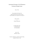
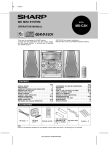
USER'S GUIDE & SAFETY MANUAL
Figure-8 Eliminator Trailer
CONDUX
Important Safety Notice
Read and understand all procedures and safety instructions before using a Condux Figure-8 Eliminator
Trailer. Observe all safety information on this page and note specific safety requirementsas explained
by procedures in this manual. Failure to follow these instructions could result in serious personal injury
or death.
ADVERTENCIA:
Favor de leer y comprender todas las instucciones de operación y seguridad antes de usar la máquina. Si
Ud. no comprende las instrucciones favor de consultarle a su jefe.
READ MANUAL
FIRST
Save this user’s guide for future reference.
COMMUNICATIONS WITH THE MANUFACTURER
For any information related to the machine (use, maintenance, spare parts) always state Model, Serial
Number, Manufacturing Year and Order. This data can be found in the machine identification table.
Manufacturer:
Condux International Inc.
145 Kingswood Rd
Mankato, MN 56002-0247
1-507-387-6576
Fax 1-507-387-1442
Internet: http://www.condux.com
E-mail: [email protected]
If you have questions on:
SAFETY - OPERATIONS - APPLICATIONS
CALL 1-800-533-2077
CONDUX
2
Table of Contents
1
Technical Specifications . . . . . . . . . . . . . . . . . . . . . . . . . . . . . . . . . . . . . . . . . . . 4
2
Safe Operating Procedures . . . . . . . . . . . . . . . . . . . . . . . . . . . . . . . . . . . . . . . . . 6
3
Jobsite Set-Up Guidelines . . . . . . . . . . . . . . . . . . . . . . . . . . . . . . . . . . . . . . . . . . 7
4
Electronic Control Features and Operation . . . . . . . . . . . . . . . . . . . . . . . . . . . . . 8
A. Hand-Held Wired Remote Controller. . . . . . . . . . . . . . . . . . . . . . . . . . . . 8
B. Electronic Machine Controller . . . . . . . . . . . . . . . . . . . . . . . . . . . . . . . . 10
C. Filters, Gate and Emergency Stop Details . . . . . . . . . . . . . . . . . . . . . . 10
5
Prepare for Operation . . . . . . . . . . . . . . . . . . . . . . . . . . . . . . . . . . . . . . . . . . . . 12
6
Load Cable . . . . . . . . . . . . . . . . . . . . . . . . . . . . . . . . . . . . . . . . . . . . . . . . . . . . 16
7
Power Winding . . . . . . . . . . . . . . . . . . . . . . . . . . . . . . . . . . . . . . . . . . . . . . . . . 20
8
Unload Cable . . . . . . . . . . . . . . . . . . . . . . . . . . . . . . . . . . . . . . . . . . . . . . . . . . 22
9
Prepare for Transport . . . . . . . . . . . . . . . . . . . . . . . . . . . . . . . . . . . . . . . . . . . . 23
10
Service and Maintenance . . . . . . . . . . . . . . . . . . . . . . . . . . . . . . . . . . . . . . . . . 24
11
Troubleshooting Guide . . . . . . . . . . . . . . . . . . . . . . . . . . . . . . . . . . . . . . . . . . . 24
12
Appendices . . . . . . . . . . . . . . . . . . . . . . . . . . . . . . . . . . . . . . . . . . . . . . . . . . . . 25
A. Parameters Settings . . . . . . . . . . . . . . . . . . . . . . . . . . . . . . . . . . . . . . . 25
B. Replacement Parts . . . . . . . . . . . . . . . . . . . . . . . . . . . . . . . . . . . . . . . . 26
13
Warranty Information . . . . . . . . . . . . . . . . . . . . . . . . . . . . . . . . . . . . . . . . . . . . . 27
3
Technical Information
1.
The Condux Figure-8 Eliminator Trailer is designed to greatly reduce cable splicing
and the need to manually “figure-eight” cable by allowing longer continuous runs
when no cable end is available. The Trailer removes cable from a cable reel, and
then dispenses it.
This unit is not intended for use where cable ends are available, nor is it a device for
transporting cable.
Do not figure-eight any dual strength member fiber optic cable using the Condux
Figure-8 Eliminator Trailer. Condux will not warranty or be held liable for any cable
damage resulting from the use of dual strength member fiber optic cable on the
Condux Figure-8 Eliminator Trailer.
In addition, the Condux Figure-8 Eliminator Trailer can be used as a hydraulic power
source in tandem with a Condux Fiber Optic Cable Blower.
• Figure 8 Eliminator trailer used to eliminate the need to manually figure-eight
GENERAL SPECIFICATIONS
fiber optic cable.
• Electronic
Figure-8
Eliminator control system to control all functions of the trailer.
Used to eliminate the need to manually figure-eight fiber optic cable.
Trailer
• Single
person operation.
Electronic
Control
• Drum
and arm
assembly
fully
enclosed
(four sides) by safety cages.
Control
all functions
of the
trailer.
System
• Cable to be loaded from ground level without having to climb into
Drum & Arm
Assembly
Fully doors
enclosedthrough
on all foursafety
sides bycages.
safety cages.
trailer
- access
• Storage for Loaded
remotefrom
controller
and
its harness.
ground level
without
having to climb into trailer - access doors through
Loading Cable
safety cages.
• Freewheel mode
with variable drag - adjustable through electronic controls.
Freewheel
Mode when
with Adjustable
controls,
used when
is being
pulled off the drum by
Used
cable is through
being electronic
pulled off
the drum
by cable
the FO
Blower.
Variable Drag Fiber Optic Blower.
• Arm assembly can be free wheel by switching on the solenoid.
Arm
Can be
by switching
on the disengage
arm switch.
• AllAssembly
components
tofreewheel
be made
of non-corrosive
materials
or be plated
or painted.
Arm Placement Arms must be locked into position during transport to prevent the beam from fatiguing.
• Arms must be locked into position during transport to prevent the beam
Trailer tofrom
be used
for
Trailer to be used for handling cable in figure-8 situation only. Not for transporting
fatiguing.
Handling Cable cable.
• Trailer is to be used for handling cable in a figure 8 situation only. Not for
transporting cable. Occasional transport of cable may be required to
reposition the trailer on the job site.
CABLE HANDLING SPECIFICATIONS
Maximum
Cable
B. CABLE
HANDLING
1.05"SPECIFICATIONS
(26.67 mm)
Diameter
•
Maximum
cable
diameter of 1.05 inch.
Max. Cable Loading
160 lb. (712 N)
Tension
• Theoretical
cable pulling tension of 187 lbs.
•
Minimum
bend
radius of 20 times the cable diameter through the guide roller
Minimum Bend Radius 20 times the cable diameter through guide roller (20 x 1.05= 21" (533 mm) bend radius)
blocks (20 * 1.05 = 21" bend radius).
Minimum Drum
• Minimum
drum
diameter
42" (1,067
mm) 42 inches.
Diameter
• Average cable
loading
speed 612 ft/ min or 40 RPM.
Maximum speed is 785 ft/min (239 m/min) on a full drum, Maximum speed is 440 ft/min
Cable Loading Speed
• Roller blocks
can
be on
easily
operated
with one hand.
(134
m/min)
an empty
drum
• Cable
capacity
of
44000
ft
of
1/2"
cable,
20,000 ft of 3/4" cable, 11000 ft of
Arm Speed 40 RPM
1.05" cable.
Roller Block Operation
Easily operated with one hand.
C. TRAILER SPECIFICATIONS
Stabilizer Jacks Manual outrigger jacks.
• Dual axle, rated for 12,000 lb capacity.
48,000
ft of 1/2"brake.
diameter cable (15 km of 13 mm cable)
• Electric brake
or surge
• Pintle ring hitch
for
electric
brake and ball hitch for surge brake.
31,000 ft of 5/8" diameter cable (10 km of 16 mm cable)
• Dual safety chains, minimum 10,000 lb capacity
Cable Capacity
22,000 ft of 3/4" diameter cable (7 km of 19 mm cable)
16,000 ft of 7/8" diameter cable (5 km of 22 mm cable)
12,000 ft of 1" diameter cable (4 km of 25 mm cable)
4
• Full DOT approved lighting package with reflective tape
• Front tongue jack, rated for 7,000 lb capacity.
TRAILER
• Target trailer weight 5,500
lb. SPECIFICATIONS
• TrailerAxle
widthDual
of 8'
ft.rated for 12,000 lb. (5,443 kg) capacity
axle,
• Spare tire included.
Brakes tongue
Electric weight 500 lb.
• Maximum
Hitch Pintle ring hitch for electric brake
D. HYDRAULIC
SPECIFICATIONS
16 HP
gasoline
engine
at 3000
RPM (16 HP diesel engine is an option).
Dual•Safety
Chains
Minimum
10,000set
lb (4,536
kg) capacity
• 8.4 cc or 0.51 cu. in. Sunstrand pump is used to generate up to 6.5 GPM fo
Lighting fluid.
Full DOT approved lighting package with reflective tape
hydraulic
• System pressure
is set at 2500 psi on the apitech valve.
Front Tongue Jack
Rated for 7,000 lb. (3,175 kg) capacity
• 12 Gallon fuel tank estimated to last up to 12 hours of operation.
•Trailer
Hydraulic
sight
Weight oil6,500
lb. gauge
(2,948 kg)is mounted on hydraulic tank to monitor oil level.
• A 5 micron high pressure and 10 micron low filter are used to keep the
Trailer Dimension
Size oil8'clean.
(2.44 m)Both
wide x filters
9' 6" (2.90
high x 21' 6"
long when elements
hydraulic
willm)indicate
on(6.55
them)ECB
are plug.
Tongue Weight 600-650 lb. (272-295 kg)
• Apitech valve controlled (ECB controlled) hydraulic ME-24 Ross motor to
drive arms. Motor to have pulse sensor (30 pulses per rev).
• Apitech valve controlled
(ECB controlled) 56 inches hydraulic cylinder to
HYDRAULIC SPECIFICATIONS
move drum. Drum to have potentiometer mounted to provide signal feedback
16 HP @ 3170 RPM (12 kW @ 3170 RPM) Briggs & Stratton V-Twin Vanguaard
on drum
Enginelocation.
*16 HP (12 kW) Diesel engine is an option
• 2500 psi, 6.5 gpm external hydraulic circuit, controlled by Apitech valve
System
Pressure
3,000 psi Plumbed
(207 bar)
(ECB
controlled).
at rear of trailer with quick connects for
Condux FO Blower.
Hydraulic Flowrate 7 gpm (26 lpm)
OF RANGE
• Thermostatic control valve is used on the inlet of OUT
the cooler
to prevent
hydraulic
flowing
7.8 HP
the
temperature has yet
Fuel
Capacity fluid
12 Gallon
(45 through
liters) estimated
to lastcooler
up to 12when
hours of
operation
to reach 100 C.
Hydraulic Fluid Sight
Gauge With
Mounted on hydraulic tank to monitor fluid level and fluid temperature
ThermometerCONTROL SYSTEM SPECIFICATIONS
E. ELECTRONIC
5 Micron high pressure and 10 micron low pressure filters used to keep hydraulic oil
ContainedFiltration
within aclean.
separate set of documents:
• Remote Electronic Control Box Specification: K:\PRODUCT\Product Dev
2,500 psi (172 bar), 6.5 gpm (25 lpm) external hydraulic circuit.
Projects\1995\95—52
Figure 8 Trailer\Electronic Controls\Electronic
External
Hydraulics
functions.lwp
Plumbed at rear of trailer with quick connects for Condux Fiber Optic Blower.
• Machine Electronic
Control Box Specification: K:\PRODUCT\Product Dev
Thermostatic Control
Used on inlet of the cooler to prevent hydraulic fluid flowing through 7.8 HP (5.8 kW)
Projects\1995\95—52
Figure 8has
Trailer\Electronic
Valve cooler when temperature
yet to reach 100 C. Controls\Machine Control
Panel.lwp
ELECTRICAL SPECIFICATIONS
/ ELECTRONIC SPECIFICATIONS
F. ELECTRICAL / ELECTRONIC
• 12 volt
DC electrical
Electrical
System
12 volt DC system.
• Two12 VDC battery.
Batteries
12 volt VDC is
Batteries
• A 20
ampereTwo
attenuettor
used to generate enough power for the
electrical system.
Controls: throttle, arm disengage, strobe lights, work light, blower and controller
OUT
RANGE
switches
with
fuses, also
the work
hour meter,
stop
switch,
hydraulic
system
Panelfree
• Control
Throttle,
wheel,
strobe
lights,
light,emergency
blower
andOF
controller
switches
pressure, fuel gauge, choke and push start button.
with fuse are place on the control panel.
Glow plug
Plug isOffered
diesel engine.
engine
• Glow
offer for
forthediesel
• Hour meter,Two
emergency
switch,
hydraulic
fuelspecification.
gauge choke
strobe and four
clearance
lights aresystem
offered topressure,
satisfy the DOT
Work
Lights
light isbutton
offered to
operate
machine
the control
dark.
and push start
are
alsothe
place
on inthe
panel.
Charges
through
main system,
andare
it is offered
isolated bytoa satisfy
diode to prevent
drawing from this
strobe and
four
clearance
lights
the DOT
Isolated •12Two
VDC Power
power supply for the work light, strobe lights, starter, blower, free wheel solenoid and
Supply
for
ECB
specification.
throttle.
Limit Switches
Rear Electric Turk
Connector
Storage Area
Mounts
On all openings and tipping gates
To power to Fiber Optic Cable Blower
Secured, weather resistant, and shock absorbing for the remote control and 65' (20 m)
of control cable.
For remote in/near control panel, also a mount on the Fiber Optic Cable Blower for the
remote.
5
Safe Operating Practices
2.
Read and understand all procedures and safety instructions before using the Condux
Figure-8 Eliminator Trailer. Observe all safety information on this page and note
specific safety requirements as explained by procedures called out in this manual.
Failure to follow these instructions could result in serious personal injury, property
damage or death.
A. WORK AREA SAFETY
1. Wear personal protective equipment: hard hat, safety glasses, safety shoes, and
leather work gloves.
2. The safe operation of this equipment requires that the operators be on stable
footing.
3. Stay clear of cables or lines under tension.
4. Do not place cable spool too close to unit. Place the spool far enough away
from the unit to ensure proper control.
5. Do not tamper with relief valves or pressure reducing valves.
B. HYDRAULIC DEVICES
Escaping fluids under pressure can penetrate the skin and cause serious personal
injury. Observe the following precautions to avoid hydraulic hazards:
1. Tighten all connections before applying pressure. Relieve pressure when
connecting or disconnecting hoses when servicing the unit.
2. Check for leaks with a piece of cardboard. Do not use your hands!
3. Do not exceed working pressure of hydraulic hoses.
4. Visually inspect hoses regularly and replace if damaged.
C. ELECTRIC DEVICES
The Hand-Held Wired Remote Controller is an electrical device. Electric shock
hazards exist that could result in severe personal injury or death. Observe the
following precautions to avoid electrical hazards:
1. Do not operate in or near water. This includes setting the Hand-Held Wired
Remote Controller on a wet surface or exposing them to rain.
2. Do not remove cover of the Hand-Held Wired Remote Controller or Electronic
Machine Controller. There are no user-serviceable parts inside. Refer servicing
to qualified service personnel.
3. The Hydraulic Power Unit Controls Power Switch and Controller Power Switch
should be in the off position before connecting or disconnecting any cords.
6
Jobsite Set-Up Guidelines
Time spent planning your equipment’s placement (layout) at the job site will benefit
both the operation of the equipment and the safety of your crew at the site. It is
best to determine the layout of all equipment before disconnecting, stabilizing and
leveling the Figure-8 Eliminator Trailer. Because no two job sites are the same, the
illustrations that follow should be used as general guidelines to get the most benefit
and safest operation from your Figure-8 Eliminator Trailer.
3.
Cable Installation—First Run
Prepare Figure-8 Eliminator Trailer for Cable Loading
Load Cable to Figure-8 Eliminator Trailer
Cable Installation—Second Run
7
Electronic Control Features and Operation
4.
A. HAND-HELD WIRED REMOTE CONTROLLER
Load Dial
• Controls the speed of the rotating arms from 0 rpm to maximum 40 rpm.
Load Drum button
• Moves the drum to the rear of the machine so the cable can be loaded onto
the machine.
• Stop button will stop the drum from moving and stop this function.
• Pressing the Load Drum button while the function is active will have the same
effect as pressing the Stop button.
Transport Drum button
• Moves the drum to the front of the machine for transport.
• Stop button will stop the drum from moving and stop this function.
• Pressing the Transport Drum button while the function is active will have the
same effect as pressing the Stop button.
Start / On button
• Starts the machine so the Load Dial is functional and allows the arms
to rotate.
• Stop button will stop the arms from rotating and stop this function.
• Load Dial must be turned all the way to zero (counterclockwise) in order to activate the start button. LED will flash if the Load Dial is not all the way to zero.
4 digit 7 segment LED display
• Normally displays the cable diameter in millimeters or the Drum Position.
• Also displays error codes when an error condition is encountered: FL 1-FULL
if the pressure filter is full; FL 2-FULL if the return filter is full; or door-OPEn
when one of the safety gates is open. These error conditions will flash between
the first and second words and will display for 5-10 seconds before going
back to displaying the cable diameter or Drum Position. They will cycle on
approximately every 20-30 seconds.
• An additional error code will be displayed when connected to the Condux FO
Blower and the blower has been stopped by the blower electronics: FOCBStOP. This error condition will flash between the first and second words and will
display as long as the trailer has been disabled by the blower. This condition
can be cleared by pressing the Stop button.
8
Stop button
• This button will stop all operations of the machine.
• LED beside button is lit when none of the other functions are operating. Also
functions as a “power on” indicator.
• If arms are rotating, they will take approximately 2 seconds to stop.
• If the Condux FO Blower has stopped the machine, pressing the Stop button will
clear the stop forced by the blower.
+ / In / Up button and - / Out / Down button
• Increments the cable diameter when the Cable Diameter LED is selected.
• Moves the Drum Position backwards or forwards while loading or
unloading cable.
Select button
• Allows selection between Cable Diameter and Drum Position.
Cable Diameter LED
• Indicates that the cable diameter can be adjusted up or down with the
+ / - buttons.
• Cable diameter can be adjusted only when NOT loading or unloading cable.
Cannot be adjusted when Load Drum or Transport Drum are operating or when
Condux FO Blower has stopped the machine.
Drum Position LED
• Drum Position can be adjusted at any time when loading or unloading cable.
• (+) Key speeds drum up, (-) key slows drum down.
• Readout on the LCD display is relative to the Drum Position on the trailer and is
not an indication of speed or distance.
LH Stab Jack & RH Stab Jack LEDs
• These functions are not used.
Drag Dial
• Controls the amount of drag on the rotating arms when in free wheel mode.
• Dial will control drag from very little drag on the arms to a very large amount
of drag.
Fiber Blower button
• Activates the external circuit that provides hydraulic fluid to the Condux
FO Blower.
• LED beside button is lit when the circuit is activated.
• Free Wheel button and function will also be activated when the Fiber Blower
button is pressed.
• Stop button will remove power from this circuit and stop this function and the
free wheel function, both LED’s will go out.
• Pressing the Fiber Blower button while the function is active will close the
hydraulic circuit and the fiber blower LED will go out, however, the Free Wheel
button and function will NOT be stopped.
Free Wheel button
• Places the trailer into free wheel mode.
• Free Wheel button and function will also be activated when the Fiber Blower
button is pressed. However, the Fiber Blower button and function will NOT be
automatically activated when the Free Wheel button is pressed.
• Stop button will stop this function and the fiber blower function.
• Pressing the Free Wheel button while the function is active will stop the free
wheel mode and the Fiber Blower will also be stopped.
9
B. ELECTRONIC MACHINE CONTROLLER
Refer to page 11 for a full explanation of the Electronic Machine Controller functions.
▲
Pressure Filter
When the Pressure
Filter is contaminated
and restricts the flow of
oil, the pressure build
up in the canister will
cause the indicator
contacts to open or an open circuit condition occurs from a broken cable or
terminal, the following is displayed. The trailer will continue to operate at a
reduced performance level.
Green LED
▲
C. FILTERS, GATE & EMERGENCY STOP DETAILS
The Filters, Gate and Emergency Stop devices are connected in a fail-safe
configuration. This means, these devices require a closed contact in normal working
condition. When the circuit goes open circuit, a fault condition results. The following
illustrations indicate the expected result.
Red LED
▲
Cage Gates
When the Access
Doors are opened or
the Tilt Panels are not
tilted out, or the circuit
to the Access Door
sensor is damaged, the following is displayed. The trailer will NOT continue
to operate and the condition must be corrected.
▲
▲
Emergency Stop
When the Emergency
Green LED
Stop is activated or the
Red LED
circuit to the E/Stop is
damaged the following
will be displayed. The
trailer will NOT continue to operate and the condition must be corrected.
10
▲
Red LED
Green LED
▲
Green LED
▲
Return Filter
When the Return Filter
is contaminated and
restricts the flow of oil,
the pressure build up in
the canister will cause
the indicator contacts to open or an open circuit condition occurs from a
broken cable or terminal, the following is displayed. The trailer will continue
to operate at a reduced performance level.
Red LED
FUNCTION
DESCRIPTION
GREEN LED
RED LED
Emergency
Stop
Green LED indicates that no
Emergency Stop buttons have
been pressed.
Red LED indicates that one of
the Emergency Stop buttons
has been pressed.
Safety Cage
Green LED indicates that all
Access Doors are closed.
Red LED indicates that one
of the Access Doors is open or
the Tilt Panel is not tilted open.
Pressure Filter
Green LED indicates that
the Pressure Filter is in good
condition.
Red LED indicates that the
Pressure Filter is full and in
need of cleaning / replacing.
The Red LED will stay lit until
maintenance is completed. The
trailer will continue to operate at
a reduced performance level.
Return Filter
Green LED indicates that
the Return Filter is in good
condition.
Red LED indicates that the
Return Filter is full and in
need of cleaning / replacing.
The Red LED will stay lit until
maintenance is completed. The
trailer will continue to operate at
a reduced performance level.
Drum Circuit
Green LED indicates that the
drum valve has been activated
and the potentiometer (position
sensor) is reading the Drum
Position.
Red LED will display if the drum
is not moving.
OFF
Both LEDs would be OFF when
the Drum Circuit isn’t activated
at all.
If the drum circuit has been
activated and the drum is
moving, but the red LED is
constantly lit, the potentiometer
isn’t reading a change in the
Drum Position. This would
indicate that either the
potentiometer is bad or the
valve isn’t operating.
The red LED may flash while
the drum is moving. This is normal.
Arm Circuit
Green LED indicates that
the arm valve (server) has been
activated and the
speed sensor is reading the
motor rotation.
Blower Circuit
Green LED indicates that
the Blower Circuit has been
activated.
Jack Circuit
This function is not used.
Red LED will display if the
arm is not moving.
Both LEDs would be OFF when
the Arm Circuit isn’t activated
at all.
If the Arm Circuit has been
activated and the arm is moving,
but the red LED is constantly lit,
the speed sensor isn’t reading a
change in the arm position. This
would indicate that either the
speed sensor is bad or the valve
isn’t operating.
The red LED may flash while
the arm is moving. This is normal.
LED would be OFF when the
Blower Circuit isn’t activated
at all.
11
Prepare for Operation
5.
It is essential that the Figure-8 Eliminator Trailer be properly set up before operation.
Using the following procedure will allow the unit to be set up in a short period of time
and yield optimum performance.
A. The trailer may be disconnected from the tow vehicle or left connected,
depending on your specific job site conditions.
B. Use wheel chocks (not included) to prevent trailer movement.
C. Disconnect Arm Lock. Unscrew the locking mechanism (Figure 1). Fold back
(Figure 2) and secure with safety pin (Figure 3).
Figure 1. Disconnect Arm Lock
Figure 3. Secure With Safety Pin
12
Figure 2. Fold Back Arm
Figure 4. Jack Mounts
D. Stabilize the trailer. Use only the
adjustable leveling jacks (3 supplied) for
trailer stabilizing and leveling. Jacks
must be placed securely on jack mounts
located on the trailer frame at the rear
of the trailer and on the tongue
(Figure 4). Do not attempt to locate
jacks in any other position. To secure a
jack in position, align jack with a jack
mount and insert safety pin (Figure 5).
Raise and lower jacks by rotating
crank handle.
E. Open Tilt Panels on the safety cage by
pulling the release cable located on both
the front and rear ends (Figure 6). Lock
Tilt Panels into open position with the
attached safety pin (Figure 7).
Figure 6. Open Tilt Panels
Figure 5. Align Jack with a Jack
Mount and Insert Safety Pin
Figure 7. Lock Tilt Panels Into
Open Position
13
F. Move drum into load position
NOTE: Before starting the engine, check hydraulic fluid level, engine oil level,
and diesel/gasoline fuel level.
Figure 8. Connect Electronic
Machine Controller
Figure 9. Connect Hand-Held
Wired Remote Controller
1. Hook up electronics. Connect both the Electronic Machine Controller
(Figure 8) and the Hand-Held Wired Remote Controller (Figure 9).
2. Start the engine using the electric start switch at the Electronic Machine
Controller panel (Figure 10).
IMPORTANT! It is critical to warm the hydraulic fluid to 100°F before
operating the machine. Hydraulic fluid temperature is indicated by a
thermometer in the engine compartment (Figure 9a).
3. Turn the controller on by using the switch at the Electronic Machine
Controller panel (Figure 10).
4. Engage the Engine Throttle. Pull out knob located on the Electronic
Machine Controller panel. Or, turn on the throttle switch (if equipped with
electronic throttle).
5. Push Load Drum button on the
Hand-Held Wired Remote Controller.
The drum will move and automatically
stop when in load position.
(See Section 4).
14
Figure 9a. Hydraulic Fluid
Thermometer
Figure 10. Electronic Machine Controller Panel
15
Load Cable
6.
To begin the loading procedure the cable must be threaded and secured properly
through the fairlead assembly, quad keeper rollers, double keeper rollers, cable notch
and cable clamp. Proper cable threading is essential for a successful winding.
Because there is no “free end” of the cable at this point in the installation, a procedure has been developed to thread the cable on to the drum using cable slack.
A. Open the Access Doors in the safety cage’s Tilt Panels by pulling the
release cable located on each Access Door (Figures 11 & 12).
Figure 11. Pull Release Cable
Figure 12. Open Access Doors
CAUTION: Follow cable manufacturers guidelines for minimum bend radius for
cable you are using. Failure to do so may result in permanent damage to cable.
CAUTION: Do not figure-eight any dual strength member fiber optic cable using
the Condux Figure-8 Eliminator Trailer. Condux will not warranty or be held
liable for any cable damage resulting from the use of dual strength member
fiber optic cable on the Condux Figure-8 Eliminator Trailer.
B. Pull out slack from the cable reel to pass at least 20 ft. (6.1 m) beyond
the front (engine) end of the Figure-8 Eliminator Trailer (Figure 13).
C. Turn on the Arm Disengage switch on the Electronic Machine Controller
panel (Figure 10).
Figure 13. Cable Slack
16
Figure 14. Position First Quad
Block Horizontally
Figure 15. Open Rear Fairlead
Assembly
D. Rotate arms manually until the far rearward quad block is in a horizontal
position (Figure 14).
E. Open rear fairlead assembly (Figure
15) and lay cable in place (Figure 16).
Important! Cable is loaded from the
back of the trailer to the front using
additional cable from the cable reel,
NOT from the cable slack pulled out in
step B.
F. Open the quad keeper roller by lifting
the roller and pin from its seat
(Figure 17) and lay cable in place.
G.Close and lock the quad keeper roller
(Figure 18).
Figure 16. Lay Cable In Place
Figure 17. LIft Roller And Pin
From Seat And Place Cable
Figure 18. Close and Lock Quad
Keeper Roller
17
H. Close and lock the fairlead roller assembly (Figure 19).
I. Proceed to next keeper roller on the arm. Continue to rotate arms
manually and be sure to extract cable from the reel, not from the slack
pulled out in step B.
Figure 19. Close and Lock
Fairlead Roller
Figure 20. Place Cable In Next
Quad Keeper Roller
J. Open quad keeper roller and lay cable in place as in step F. Close and
lock quad keeper roller as in step G (Figure 20).
K. Manually rotate arms to locate 3 double keeper rollers (Figure 21) in
sequence. Follow the procedure to open, lay in cable, and close as in steps
F and G (Figure 22).
Figure 21. Locate 3 Double
Keeper Rollers
Figure 22. Place Cable In Double
Keeper Rollers
L. Manually rotate arms to locate the final quad keeper roller and follow
the procedure to open, lay in cable and close as in steps F and G.
18
M. Manually spin arms around until the cable nests on the drum (Figure 23).
N. Nest cable in notch on drum (Figure 24).
Figure 23. Manually Spin Arms
Figure 24. Nest Cable In Notch
On Drum
O. Open cable clamp and secure cable inside (Figure 25).
P. Manually turn arms to wrap 2 complete wraps on drum.
Q. Turn off Arm Disengage switch.
R. Tighten manual wraps against front of drum (Figure 26).
S. Close Access Doors on Tilt Panels and at rear of trailer.
Figure 25. Open Cable Clamp
And Secure Cable Inside
Figure 26. Tighten Manual Wraps
19
Power Winding
7.
The Condux Figure-8 Eliminator Trailer is capable of winding cable at an average
speed of 600 ft/min (179 m/min) or about 40 RPM. This productivity will vary with
cable diameter, job site layout and equipment condition.
Important! Always start the winding operation slowly, and gradually increase
speed to attain maximum operation efficiency and cable safety.
The power winding procedure requires fluent use of both electronic controllers, the
Electronic Machine Controller and the Hand-Held Wired Remote Controller. Review
the features and functions of the electronic controllers in Section 4 of this manual
before beginning the power winding operation.
The drum moves a distance of one cable
diameter for every rotation of the arm
during power winding. It may be
necessary to make minor adjustments in
the speed of the drum movement during
winding to ensure cable nests neatly on
the drum (Figure 27). Note that the cable
being placed needs to be slightly behind
the cable wrapped on the drum to keep
wraps tight (Figure 27).
Important! Large spaces between
cable or overlapping of cable will
compromise the unloading procedure
(Section 8) or may cause the drum to
fill prematurely. Use the following
corrective actions when needed to
keep even wraps of cable on the drum.
Overlapping Cable: While loading, you
may double the speed of the drum for
every rotation of the arm by pressing the
(+) key on the Hand-Held Wired Remote
Controller. This means the drum will
move 2 cable diameters for every rotation
of
the arm.
Space Between Cable: While loading you
may half the speed of the drum for every
rotation of the arm by pressing the (-) key
on the Hand-Held Wired Remote
Controller. This means the drum will
move 1/2 a cable diameter for every rotation of the arm.
Follow steps A through H for trouble-free
Power Winding (Cable Loading) operation.
Figure 27. Proper Cable Winding
20
CAUTION! Side Tilt Panels must remain open and pinned, Access Doors must
remain closed during Power Winding operations. Be sure side panels are
securely pinned in the open position. Failure to do this may cause damage to
machine and cable.
A. Turn on electronic controller’s switch on control panel.
B. Input cable diameter using the Select and (+) and (-) keys on the Hand-Held
Wired Remote Controller. The reading is in millimeters only.
NOTE: A Vernier Caliper (supplied) or a cable diameter gauge (not included) can be
used to measure outside cable diameter (OD) on site.
C. Start the engine by depressing the electric start button on the Electronic
Machine Controller panel.
D. Turn the throttle up on the engine.
E. Be sure the Load Dial on the Hand-Held Wired Remote Controller is set at
zero (counterclockwise). The loading process will not start if the Load Dial
is not set at zero.
F. Press the Start button on the
Hand-Held Wired Remote. The
LED will come on. If the LED is
flashing, the Load Dial was not set
to zero. Turn the Load Dial completely to zero (counterclockwise)
and press the Start button again.
G. Begin winding by gradually turning
the Load Dial on the Hand-Held
Wired Remote Controller
clockwise (Figure 28). Winding
speed will continue to increase
as the dial is turned clockwise
and will decrease by turning
counterclockwise.
Figure 28. Wind Load Dial
Clockwise
Important! Always start the winding operation slowly, and gradually increase
speed to attain maximum operation efficiency and cable safety.
Important! The operation may be shut down immediately by any one of the
following actions:
• Stop button is depressed on the Hand-Held Wired Remote Controller.
• Access Door is opened.
• Emergency Stop button is depressed at the Electronic Machine
Controller panel. (Requires restart of the electronic controllers.)
H. The drum will automatically reverse directions at the ends of the drum as
the power winding continues.
21
I. Discontinue power winding when there are approximately 5 to 6
wraps of cable left on the cable spool. The last 5 to 6 wraps should be
removed from the spool by hand. Turn Load Dial counterclockwise to zero
and stop engine by turning off at machine control panel.
CAUTION! Remove the last 5 to 6 wraps of cable slowly by hand to avoid end
of cable whipping freely off the cable spool during power winding.
NOTE: If you must turn off the controllers during the power winding operation at any
time before it is complete, there is a special procedure that must be followed to
resume operation. The drum direction must be noted and corrected if necessary.
1. Turn on both electronic controllers, Electronic Machine Controller and
Hand-Held Wired Remote Controller with switch on main panel.
2. Start the engine by depressing the electric start button on the machine
control panel.
3. Turn the throttle up on the engine.
4. Be sure the Load Dial on the Hand-Held Wired Remote Controller is set at zero
(counterclockwise). The loading process will not start if the Load Dial is not set
at zero. Press the Start button and begin winding the cable.
5. If the drum begins to move in the wrong direction, stop the operation promptly
by depressing the Stop button on the Hand-Held Wired Remote Controller.
6. Change the drum movement to the correct direction by pushing the Load Drum
or Transport Drum button on the Hand-Held Wired Remote Controller.
• Load Drum (moves drum towards the rear)
• Transport Drum (moves drum towards the front)
7. Resume power winding operations from step 7-F.
Unload Cable
8.
Cable may be unloaded on to a cable reel or directly to a Condux Fiber Optic Cable
Blower. Unloading Cable requires the Figure-8 Eliminator Trailer to be in
Free Wheel mode and requires drag on the cable at all times to avoid whiplashing
and tangling of cable.
A. Start the Engine
B. Start the Controller
C. Increase Throttle
D. Press Free Wheel Button on hand-held wired Remote Controller
E. Check Drum movement for proper direction. If the drum begins to move in the
wrong direction, stop the operation promptly by depressing the Stop button on
the Hand-Held Wired Remote Controller. Change the drum movement to the
correct direction by pushing the Load Drum button or Transport Drum button on
the Hand-Held Wired Remote Controller.
22
F. Use the Drag dial to adjust the amount of drag placed on the arms during
unloading. It is essential to keep cable from developing slack. Start with
very little drag and increase to desired level and monitor throughout entire
unloading process.
G. Remove last 4-5 wraps manually. Activate the Arm Disengage switch on the
Electronic Machine Controller panel and rotate arms by hand.
H. Remove cable from quad and single keeper rollers using the procedure
described in Section 7.
Prepare For Transport
Care should always be taken to position drum for transport and properly stow
components in the Condux Figure-8 Eliminator Trailer. After cable is unloaded,
prepare for transport in the following way:
CAUTION: Condux Figure-8 Eliminator Trailer is not intended to transport
cable. Cable should be completely unloaded before transporting trailer to
another location.
9.
A. Move drum into Transport position by pressing the Transport Drum key on the
Hand-Held Wired Remote Controller. Drum should be at the far forward position
for transport.
B. Release the arms with the Arm Disengage switch on the control panel.
Figure 29. Mount Arm Lock
Figure 30. Stow Controllers
C. Mount the Arm Lock to the arm housing (Figure 29).
D. Turn off the Arm Disengage switch.
E. Shut engine off.
F. Close Access Doors at sides and rear of trailer.
G. Close Tilt Panels on both sides of trailer.
23
H. Turn off Machine and Hand-Held Wired Remote Controller.
I. Disconnect electronics and stow controllers in bin below Electronic Machine
Controller (Figure 30).
J. Pull locking pin and secure in hole below latch for transport.
K. Release jacks by turning crank. Wind jack up to approximately 3 inches
(76.2 mm) above surface and rotate jack 90 degrees on its mount. Secure
with pin for transport.
L. Connect trailer to tow vehicle (if previously disconnected).
Service & Maintenance
10.
A. Follow Briggs and Stratton Owners Manual for engine maintenance (the engine
oil drain is located beneath the trailer).
B. Inspect tires (LT 225/75R16) for proper wear and always keep inflated to the
specification denoted on the sidewall of the tire.
C. Inspect lighting and replace bulbs as required.
D. Maintain the hydraulic fluid with auto transmission fluid (Mercon/Dexron III) at
least three quarter tank.
E. Replace filters and auto transmission fluid when it turns brown color or after
500 hours of operation (the reservoir drain is located beneath the trailer).
Troubleshooting Guide
11.
24
Problem
Solution
Drum moving in the wrong direction
while loading and unloading after the
machine was shut down.
Move the drum towards engine using
transport drum button or move it
towards the arms using the load drum
button to guide the controller in the
correct direction of the drum.
Drum is moving faster or slower than
the arms.
The drum speed can be adjusted
using ‘+’ or ‘-’ button depending on the
drum direction and speed.
Machine will not run after pressing
load button or the load button LED
kept turning off after pushing it.
Check the Access Doors if they are
closed and Tilt Panels are tilted.
Load LED is flashing after pressed.
Turn Load Dial completely
counterclockwise (to zero) and press
button again.
Parameter Settings
These parameter settings are loaded into the controllers at the factory and should
not need adjustment. Please contact the factory before making any changes to the
parameter settings and for instructions on getting into the programming mode.
Display
Actual Setting
Setting
Command/ Procedure
CBLE
15
15
Default cable diameter.
POSN
0-2500
0-2500
A.
APPENDIX
Drum position reading of the
potentiometer. It is used to locate the
drum loading and transport position.
B1
55
Bias transport to engine—to set the drum
sensitivity moving toward the engine.
B2
55
Bias load to server—to set the drum
sensitivity moving toward the arms.
B3
55
Bias server load—to set the motor
sensitivity rotating the arms.
B4
LENG
0
0
1360
1360
Bias free wheel—keep it at zero.
Drum length measuring between the two
flanges—always set it at 1360.
SCNT
336
Drum position for loading.
ECNT
2026
Drum position for transporting.
GAIN
5
5
D1
100
100
Minimum drag.
D2
60
60
Maximum drag.
SLAG
0
0
Pulses on server before spool
move—always set it at zero.
7PNH
140
146
The speed of the drum moving to
transport position.
LOAD
140
141
The speed of the drum moving to
load position.
25
Replacement Parts
B.
APPENDIX
26
Part Number
Description
1
02267200
Kit, Tail Light-Waterproof Low Profile
2
02278509
Connector, Trailer 7-Way Blade
3
02288776
Cord set, Fig 8 Remote to Blower
4
02288779
Latch, T Handle-W/Lock
5
02288812
Spring, Gas
6
02288814
Cord set, Fig 8 Potentiometer
7
02288815
Cord set, Fig 8 Motor Signal
8
02288875
Caliper, Cable Diameter Fig-8
9
02288896
Bag, Fig 8 Remote Controller
10
08735110
Controller, Machine-Fig 8 Trailer
11
08735120
Control, Hand Remote-Fig 8 Trailer
12
08735130
Cord set, Fig 8 Remote Control
13
08735712
Tow ball, Male-Lock Assembly
14
08737001
Kit, Filter Replacement
15
08737002
Kit, Receptacle Turck Replacement
16
08737003
Kit, Limit Switch Replacement
17
08737004
Kit, Potentiometer Replacement
18
08737005
Kit, Channel Replacement
19
08737006
Kit, Hydraulic Hose Replacement
20
08737007
Kit, Quick Disconnect Replacement
21
08737008
Kit, Drum Eccentric Roller
22
08737009
Kit, Drum Horizontal Roller
23
08737010
Kit, Cable Blocks Accessories
24
08737011
Kit, V Quad Block Roller
25
08737012
Kit, Quad Block Roller
26
08737013
Kit, Dual Block Roller
27
08737014
Kit, Fairlead Latch
28
08737015
Kit, Fairlead Roller
Warranty Information
A. FACTORY ASSISTANCE
Condux International can provide further advice regarding any problems with the
installation, service, assembly, or disassembly of the Figure-8 Eliminator Trailer. Call
toll free at 1-800-533-2077 (USA and Canada) or 1-507-387-6576 and ask for
assistance. The Figure-8 Eliminator Trailer can be returned to the factory at any time
for service or repair; however, a Return Material Authorization (RMA) must be
obtained from Condux before shipping. Condux will not accept returned items without
an RMA.
13.
B. LIMITED WARRANTY
Condux International, Inc. extends the following warranty to the original purchaser of
these goods for use, subject to the qualifications indicated: Condux International,
Incorporated warrants to the original purchaser for use that the goods or any
component thereof manufactured by Condux International will be free from defects in
workmanship for the period of one year from the date of purchase. Provided such
goods are installed, maintained, and used in accordance with Condux’s written
instructions.
Lack of routine maintenance as specified in the maintenance section of the
User’s Guide will void the warranty.
Components not manufactured by Condux International but used within the assembly
provided by Condux International are subject to the warranty period as specified by
the individual manufacturer of said component, provided such goods are installed,
maintained, and used in accordance with Condux’s and the original manufacturer’s
written instructions.
Condux’s sole liability and the purchaser’s sole remedy for a failure of goods under
this limited warranty, and for any and all claims arising from the purchase and use of
the goods, shall be limited to the repair and replacement of the goods that do not
conform to this warranty.
To obtain repair or replacement service under the limited warranty, the purchaser
must contact the factory for a Return Material Authorization (RMA). Once obtained,
send the RMA along with the defective part or goods, transportation prepaid, to:
Condux International, Inc.
145 Kingswood Road
Mankato, MN 56001 USA
THERE ARE NO EXPRESS WARRANTIES COVERING THESE GOODS
OTHER THAN AS SET FORTH ABOVE. THE IMPLIED WARRANTIES OR
MERCHANTABILITY AND FITNESS FOR A PARTICULAR PURPOSE ARE
LIMITED IN DURATION TO ONE YEAR FROM DATE OF PURCHASE.
CONDUX ASSUMES NO LIABILITY IN CONNECTION WITH THE INSTALLATION
OR USE OF THIS PRODUCT, EXCEPT AS STATED IN THIS LIMITED WARRANTY.
CONDUX WILL IN NO EVENT BE LIABLE FOR INCIDENTAL OR
CONSEQUENTIAL DAMAGES.
27
Condux International, Inc.
P.O. Box 247 • 145 Kingswood Road, Mankato, MN 56002-0247 USA
1-507-387-6576 • 1-800-533-2077 • FAX 1-507-387-1442
Internet: http://www.condux.com • e-mail: [email protected]
28
© Copyright 2000, Condux International, Inc.
Printed in USA
Literature Part Number: 08739999
Revision Number: 1.0