1
Operator's
Manual
II:RRFTSMRN I
3 HORSEPOWER
REAR TINE TILLER
Model No: 987.293190
CAUTION:
Before using this tiller, read
this manual and follow all its
Safety Rules and Operating
Instructions.
•
•
•
•
•
Safety Rules
Assembly
Operation
Maintenance
Parts
Sears, Roebuck and Co., Hoffman Estates, IL 60179 U.S.A.
Visit the Craftsman web page: www.sears.com/craftsman
SAFETY RULES
_
CAUTION" ALWAYS DISCONNECT
SPARK PLUG WIRE AND PLACE WIRE WHERE IT
CANNOT CONTACT SPARK PLUG TO PREVENT ACCIDENTAL
STARTING WHEN SETTING UP, TRANSPORTING,
ADJUSTING
OR MAKING REPAIRS.
TRAINING
%, Read ,this Owner's Manual and
any other literature you may receive
carefully before operating this equipment. Be completely familiar with
the controls and the proper use of
this equipment. Know how to stop
the unit and disengage the controls
quickly.
2. Never allow children or untrained
adults to operate this equipment.
3. 'Keep the area of operation clear
of'all persons, particularly small chiLdren and pets. Keep bystanders at
least 25 feet from area of operation.
4. Keep in mind that the operator or
user is responsible for accidents or
hazards occurring to other people,
their property, and themselves.
5. Familiarize yourself with all of the
safety and operating decals on this
equipment and on any of its attachments or accessories.
6. Do not run engine in an enclosed
area. Engine exhaust contains carbon monoxide gas, a deadly poison
that is odorless, colorless, and tasteless. Do not operate this equipment
near buildings, windows, or air
6onditioners.
7. Do not allow hands or any other
part of the body or clothing near the
rotating tines or
near any other
moving part. The
tines begin to rotate backward
. once the engine
starts and the
Forward Clutch
Bail is engaged.
8. Before inspecting or servicing any
part of the equipment, shut off the
engine, wait for all moving parts to
come to a complete stop, disconnect
the spark plug wire from the spark
plug and move wire away from the
spark plug.
!_
9. Do not operate this equipment if
you are under the influence of alcohol, medication, or when tired or ill.
I
7. Never attempt to make any adustments while the engine is running
or the spark pug w re is connected,
except when so instructed.
PREPARATION
1. Thoroughly inspect the area
where the tiller will be used. Remove foreign objects before tilling.
2. Make sure that all control levers
are released and both wheels are in
Wheel Drive position before starting
the engine.
3. Do not operate the tiller without
wearing suitable clothing. Avoid
loose garments or jewelry that could
get caught in moving parts of the
tiller or its engine.
4. Do not operate the tiller when you
are barefoot, in sandals, sneakers or
other light footwear. Wear protective
footwear that grips well on slippery
surfaces.
5. Do not till near underground electric cables, telephone lines, pipes, or
hoses. Contact your telephone or
utility to verify locations of underground cables or lines.
6. Handle gasoline with care; it is
highly flammable and has explosive
vapors. Take the following precautions:
a. Use an approved gas container.
b. Gas caps shall never be removed or fuel added with engine running. Engine shall be
allowed to cool before refueling.
Operators shall not smoke.
c. Keep matches, cigarettes,
cigars, pipes, open flames, or
sparks away from the fuel tank
and fuel container.
d. Fill fuel tank outdoors using extreme caution. Never add fuel
indoors. Use a funnel or spout
to prevent spillage.
e. Replace all fuel tank and container caps securely.
f. If fuel is spilled, do not attempt
to start the engine, but move
the machine away from the area
of spillage and avoid creating
any source of ignition until fuel
vapors have dissipated.
OPERATION
1. Never operate the tiller unless
safety guards or other protective devices are in place.
2. Never operate the tiller without
good visibility or light.
3.' Never operate the tiller if you are'
fatigued, or under the influence of alcohol, drugs or medication.
4. Use tiller attachments and accessories when recommended. Use only
attachments and accessories
approved by the manufacturer.
5. Operators shall net tamper with
the engine-governor settings on the
machine; the governor controls the
maximum safe operating speed and
protects the engine and all moving
parts from damage caused by overspeed. Authorized service shall be
sought if a problem exists.
6. To load or unload the tiller from a
vehicle, see instructions in the "Operation" section.
7. Keep children and pets away.
8. Clear the area of bystanders
before tilling.
9. Do not run the engine in an enclosed area. Engine exhaust contains carbon monoxide gas, a deadly
poison that is odorless, colorless,
and tasteless.
10. Start the engine carefully according to instructions and with feet well
away from the tines.
11. Never pick up or carry a machine
while the engine is running.
12. Never use the tiller at high
ground speeds on hard or slippery
surfaces.
13. Never operate the tiller under
engine power if the wheels are in the
FREEWHEEL position. In FREEWHEEL, the wheels will not hold the
tiller back and the revolving tines
could propel the tiller rapidly
IT
MEANSBECOME
YOUR SAFETY
INVOLVED.
LOOK
FOR ATTENTION!!f
THIS SYMBOL TO
POINT ALERT!!!
OUT IMPORTANT
SAFETYISPRECAUTIONS.
© Sears, Roebuck and Co.
2
SAFETY RULES
backward, possibly causing loss of
control. Always engage the wheels
with the Wheel Drive Pins in WHEEL
DRIVE position before starting en_ne or engaging tines with Forward
Ibtch Bail.
14. Look behind and exercise caution when backing up.
15. The tiller could unexpectedly
bounce upward or jump backward
and be propelled toward you if the
tines strike or catch very hardpacked soil, sod, frozen ground, or
any buried obstacle such as large
stones or roots. If in doubt about tilling conditions, use the following precautions to assist you in maintaining
tiller control:
a. Walk behind and on either side
of the tiller, using one hand on
the handlebar. Relax your arm,
but use a secure hand grip.
b. Use a deep depth regulator
setting.
c. Use.slower engine speeds.
d. Clear the tilling area of big
stones, roots and other debris.
e. Avoid putting downward pressure on the handlebar. If necessary, apply slight upward
pressure to prevent the tines
from digging too deeply.
f. In an emergency, stop tines and
wheels by releasing the
Forward Clutch Bail. Do not attempt to restrain the tiller.
16. Do not overload the machine capacity by trying to till too deeply at
too fast a rate.
17. Do not operate tiller on a slope
too steep for safety, On slopes, slow
down and be sure you have good
footing, Don't let the tiller "freewheel"
down slopes.
18. Do not touch engine parts that
may be hot from operation (muffler,
fins, etc.). Make certain all parts have
cooled down before inspecting, cleaning or repairing.
19. Remember--To stop the tines
and wheels, release the Forward
Clutch Bail.
20. Do not put hands or feet near or
under rotating parts.
21. Use extreme caution when on or
crossing gravel driveways, walks or
roads. Be alert for hidden hazards
or traffic. Do not carry passengers.
22. If you hit a foreign object, stop
the engine, let all moving parts come
to a complete stop, disconnect spark
plug wire, move wire away from the
spark plug, and inspect for damage.
Repair damage before restarting.
23. Exercise caution to avoid slipping or falling.
24, If abnormal tiller vibration occurs, stop engine immediately, disconnect the spark plug wire and
move wire away from spark plu_.
Check for the cause. Carefully respect for any damage. Fix the problem before using the tiller again.
Vibration is generally a warning sign
of trouble.
25. Stop the engine, disconnect the
spark plug wire and move wire away
from spark plug after leaving the operating position, before unclogging
tines, or before making repairs, adjustments or inspections.
26. Take all possible precautions before leaving the machine unattended.
Make sure that all control levers are
released, stop engine, and disconnect
spark plug wire and move wire away
from plug to prevent accidental starting. Be sure both wheels are in the
Wheel Drive position.
27. Before cleaning, repairing or inspecting, stop the engine, let all
moving parts stop, and disconnect
spark plug wire and move wire away
from spark plug to prevent accidental
starting.
28. The flap on the tine hood must
be down when operating tiller.
7. Store gasoline in a cool, well-ventilated area, safely away from any
spark- or flame-producing equipment. Store gasoline in an approved
container, safely out of the reach of
children.
e. Refer to the Maintenance section
in this Manual for storage information
if your tiller is to be stored for an extended period.
9. If the fuel tank has to be drained,
do so outdoors.
10. Follow manufacturer's recommendations for safe loading, unloading, transport, and storage of
machine.
•
•
•
•
•
MAINTENANCE
& STORAGE
1. Never perform maintenance
when engine is running or spark plug
wire is connected except when
specifically directed to do so.
2. Keep tiller, attachments and accessories in safe working condition.
3. Check all nuts, bolts, and screws
frequently for proper tightness.
Always verify your equipment is in
safe working condition.
4. Never store the machine with fuel
in the fuel tank inside a building
where fumes may reach an open
flame or spark, or where ignition
sources are present (such as hot water and space heaters, furnaces,
clothes dryers, etc.).
5. Let the engine cool down before
storing it in an enclosure.
6. To reduce chance of a fire hazard,
keep grass, leaves, grease off engine.
3
•
•
•
TO AVOIDINJURY:
READOWNER'SMANUAL.
KNOW LOCATION AND
FUNCTION OF ALL CONTROLS,
KEEPALL SAFETYDEVICES
AND SHIELDS IN PLACE
ANDWORKING.
NEVER ALLOW CHILDREN
ORUNINSTRUCTEDADULTS
TO OPERATETILLER.
SHUT OFF ENGINE AND
DISCONNECTSPARKPLUG
WIRE BEFORE UNCLOGGING TINES OR MAKING
REPAIRS.
KEEP BYSTANDERSAWAY
FROMMACHINE,
KEEPAWAY FROM ROTATING PARTS.
USE EXTREME CAUTION
WHEN REVERSING OR
PULLINGTHEMACHINETOWARDSYOU.
WARNING:
The engine exhaust from this
product contains chemicals
knownto the State of California
to cause cancer, birth defects,
or other reproductiveharm.
CONGRATULATIONS
onyourpurchaseofa Sears
Craftsman
tiller. It hasbeendesigned,engineered
and
manufactured
to giveyouthebestpossibledependability
andperformance.
Shouldyouexperience
anyproblemsyoucannoteasily
remedy,pleasecontactyournearestSearsService
Center/Department.
Wehavecompetent,
well-trained
technJcians
andthe propertoolsto serviceor repairthis
machine.
Pleaseread and retain this manual. The instructions will
help you assemble and maintain your machine properly.
Always observe the "SAFETY RULES."
PRODUCT
SPECIFICATIONS
HORSEPOWER:
3 HP
DISPLACEMENT:
9.06 CU. IN.
FUEL CAPACITY:
2 Quarts
ENGINE OIL CAPACITY:
21 Ounces
;PARK PLUG (GAP 0.030-in.):
IGNITION:
Champion RJ-17LM*
or equivalent
Electronic
NET ENGINE WEIGHT:
25 Pounds
NET TILLER WEIGHT:
117 Pounds
• In Canada, replace spark plug with a resistor plug.
MODEL NUMBER:
987.293190
SERIAL
NUMBER:
WARNING
DATE OF
PURCHASE:
THE MODELAND SERIAL NUMBERS WILL BE
"FOUND ON A DECAL LOCATED ON THE TRANSMISSION OF YOUR MACHINE.
YOU SHOULD RECORD BOTH THE SERIAL NUMBER AND DATE OF PURCHASE AND KEEP tN A
SAFE PLACE FOR FUTURE REFERENCE.
MAINTENANCE
AGREEMENT
A Sears maintenance agreement is available on this
pr'oduct. Contact your nearest Sears store for details.
CUSTOMER
RESPONSIBILITIES
[3 Read and observe the safety rules.
This machine is equipped with an internal combustion engine and should not be used on or near any
unimproved forest-covered, brush-covered or
grass-covered land unless the engine's exhaust
system is equipped with a spark arrester meeting
applicable local or state laws (if any). If a spark
arrester is used, it should he maintained in
effective working order by the operator.
In the state of California the above is required by
law (Section 4442 of the California Public
Resources Code). Other states may have similar
laws. Federal laws apply on federal lands. This
engine is not equipped with a spark arrestor for the .
muffler,
Asparkarrester
for the muffler is
available through your nearest Sears authorized
service center. See the REPAIR PARTS section of
this manual.
[3 Follow a regular schedule in ma_intaining, caring for
and using this product.
(3 Fellow the instructions under "CUSTOMER
RESPONSIBILITIES" and "STORAGE" sections of
this manual.
LIMITED TWO-YEAR WARRANTY ON CRAFTSMAN® TILLER
For two years from the date of purchase, when this Craftsman®Tiller is maintained, lubricated, and tuned up according to the
operating and maintenanceinstructions in the owner's manual, Searswill repair,free of charge, any defect in material or
workmanship.
if this Craftsman®Tiller is used for commercial or rental purposes, this warranty applies for only 90 days from the date of
purchase.
THIS WARRANTYDOESNOT COVER:
• Expendableitemswhichbecome worn duringnormaluse, suchas tJQP,._,belts,sDarkP_Lu.g,
and air cleaner.
• Repairs necessarybecauseof operatorabuse or negligenceincludingbentcrankshaftsand the failure to maintainthe equipmentaccording to the instructionscontainedin the owner'smanual.
WARRANTYSERVICEISAVAILABLE
BYRETURNING
THECRAFTSMAN®
TILLERTOTHENEAREST
SEARSSERVICECENTERIN THE
UNITEDSTATES,THISWARRANTYAPPLIESONLYWHILETHISPRODUCTIS IN USEIN THEUNITEDSTATES.
This warranty gives you specific legalrights, and you may also have other rights whichvary from state to state.
Sears, Roebuck and Co., D/817WA, Hoffman Estates, IL 60179
•TABLE OF CONTENTS
SAFETY
RULES ...................................................
PRODUCT
WARRANTY
SPECIFICATIONS
..........................................................
ACCESSORIES
CONTENTS
..............................
....................................................
OF HARDWARE
PACKAGE
2
SERVICE
4
STORAGE
4
TROUBLESHOOTING
6
DECALS ..............................................................
30
REPAIR
PARTS - TILLER
..................................
31
REPAIR
PARTS - ENGINE
.................................
40
............ 7
ASSEMBLY
...........................................................
OPERATION
.......................................................
11
CUSTOMER
RESPONSIBILITIES
20
.....................
8
AND ADJUSTMENTS
........................
...........................................................
28
........................................
PARTS ORDERING/SERVICE
24
29
........... Back Cover
INDEX
A
F
Accessories ..................
Air Cleaner Maintenance .......
Anti-Reverse Stake ...........
Assembly ....................
6
23
13
8
B
G
Break-In Operation ...........
Belt Tension Adjustment .......
Belt Removal and Replacement
16
25
. 25
Guiding the Tiller .............
16
II
Handlebar Height Adjustment ...13
Hardware ..............
7,10, 24
C
Carburetor ..................
Checking/Adding Engine Oil ....
Checking/Adding Transmission Oil
Checking/Adjusting Belt Tension.
Checking for Oil Leaks .........
Changing Engine Oil ..........
Changing Transmission Oil .....
Cleaning ....................
Cooling System Maintenance...
Controls ....................
Cultivating ..................
23
21
21
25
23
21
22
23
23
11
18
D
Decals .....................
Depth Regulator Lever
S
Features/Controls
............
11
Forward Clutch Bail ........
12, 26
Forward Clutch Cable (Install) .... 9
Forward Clutch Cable (Replace) .26
Forward Travel ............
12, 17
........
30
13
23
23
14
23
15
21
16
40
14
23
14
16
16
28
14
2
30
18
20
19
23
14
28
T
"Filler Parts .................
Tilling ......................
Tilling Depths ................
"line Cleaning ................
Tine Removal ................
Transmission Gear Oil...10,
Troubleshooting ..............
Turning Around ..............
,_31
17
16
19
24
21, 22
29
17
M
Maintenance Schedule ........
20
Maintenance Agreement ........
4
Model/Serial Number ...........
4
Motor Oil, Adding ..........
15, 21
Motor Oil, Changing ...........
21
U
Unpacking ...................
U ntangling Tines .............
8
19
W
Warranty ....................
Wheel Drive Pins .............
0
Oil
......................
Off-Season Storage ...........
Operation ................
E
Engine:
Air Filter ..................
Carburetor ................
Choke Lever ..............
Cooling System ............
Fuel Tank .................
Oil, Checking/Adding ........
Operation .................
Part_ ....................
Recoil Start Rope ..........
Spark Plug ................
Speed ...................
Starting Engine ............
Stopping Engine ...........
Storage ..................
Throttle Lever .............
Leaks, Oil ...................
23
Loading and Unloading Tiller .... 19
Location of Controls ...........
11
Lubrication ..................
20
Safety Rules .................
Safety Decals ...............
Seedbed Preparation ..........
Service Recommendation
Checktist .................
Slopes .....................
Spark Plug ..................
Starter Rope ................
Storage ....................
15
28
11,17
4
11
RIGHT
SIDE
P
Parts List ...................
Preparation .................
Pre-Start Checklist ............
Product Specifications ..........
31
14
14
4
R
Rearward Travel .............
Recoil Starter Rope ...........
Repair Parts .................
17
14
31
FORWARr
SIDE
OPERATOR'S
POSITION
All references to LEFT and
RIGHT sides of the tiller are
given from the operator's position behind the handlebars (unless specified otherwise).
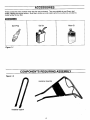
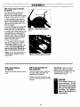
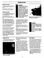
ACCESSORIES
These accessories were available when the tiller was purchased. They are available at most Sears retail
outlets, catalog and service centers. Most Sears stores can order repair parts for you when you provide the
model number of your tiller.
ACCESSORIES
GasCan
Spark Plug
Figure
Motor 0il
1-1
4,
COMPONENTS
Figure
REQUIRING ASSEMBLY
1-2
HandlebarAssembly
HandlebarSupport
6
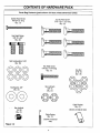
CONTENTS
OF HARDWARE
PACK
Parts Bag Contents (parts shown full size unless otherwise noted)
Slotted HeadScrew
#10-24 x 2" long
Qty.: (1)
CurvedHeadScrew
5/16"-18 x 1-1/2" long
Qty.:(6)
Hex HeadScrew
3/8"-16 x 3/4"
Qty.:(2)
Split Lockwasher,5/16"
Qty.:(6)
.©©©
©©©
Flat Washer,3/8"
Qty.:(2)
Hex Head Screw
1/4"-20 x 1-1/4" long
Qty.:(1)
Hex Nut
5/16"-18
Qty.: (6)
Hex Locknuts
3/8"-16
Qty.:(2)
©©
....
CableBracket
Qty.:(1)
Hex Locknut
1/4"-20
Qty.:(1)
(shown at reducedsize)
CableSpring
Qty.:(1)
(shown at reduced
size)
Figure
1-3
%
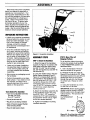
ASSEMBLY
Read these instructions completely
before you attempt to assemble or
operate your new equipment. Your
tiller has been assembled at the factory with the exception of those parts
left unassembled for shipping purposes. Steps in this section show
you how to do so. To ensure safe
and proper operation of your machine, all parts and hardware you install or adjust must be tightened securely. Use the correct tools as necessary to ensure proper tightness.
H
G
UNPACKING
INSTRUCTIONS
• Inspect your machine immediately.
Be sure neither the carton nor contents have been damaged. If you
find or have reason to suspect
damage, contact the nearest
Sears Service Center/Department
for assistance.
• Once the cardboard shipping carton is open, remove any packing
material from around the machine.
Remove any staples securing bottom of carton to wood pallet. Lift
off carton. Before disposing of the
carton or any of the packing materials, be sure to check them thoroughly for any small parts.
• Leave unit on base of pallet dur.ing assembly steps (to safely remove unit from pallet, wait until
you have installed the handlebar
assembly).
• Also remove any packaging around
the handlebar.
• Perform the assembly on a clean,
level surface. If you need to move
the machine, be careful not to
severely bend any of the control
cables on the equipment.
Tools Needed For Assembly:
• Open,end or adjustable wrenches:
One 3/8";Two 7/16";
One 1/2"; Two 9/16"
• Funnel (to add motor oil)
• Rag (for any oil cleanup needed)
• Block of Wood (to support Me tiller
when removing wheel)
B
D
Figure 2-1: Assemble handlebar.
ASSEMBLY
STEPS
STEP1: Attach the Handlebar
1. Attach the legs of the handlebar
support (A, Figure 2-1) loosely to the
inner sides of the tiller frame using
two 3/8"-16 x 3/4" hex hd. screws
(B), 3/8" flat washers (C) and 3/8"-16
hex Iocknuts (D).
2. Using the middle holes in the handlebar support brackets (E and F,
Figure 2-1), loosely attach the support brackets to the handlebar support (A) using two 5/16"-18 x 1-1/2"
curved hd. screws (G), 5/16" split
Iockwashers (H) and 5/16"-18 hex
nuts (I). NOTE: If a support bracket
will not move, loosen attaching
screw (J) and nut.
3. Attach the handlebar assembly (K)
to the handlebar support (A) using
four 5/16"-18 x 1-1/2" curved hd.
screws (G), 5/16" split Iockwashers
(H) and 5/16"-18 hex nuts (I). Tighten the four screws securely.
STEP2: Move Tiller off
ShippingPlatform
To roll the tiller without the engine
running, the wheels must be placed
in their FREEWHEEL position, as
described below.
1. Use a sturdy block of wood to
raise one wheel off the ground.
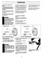
2. Remove the hair pin cotter (N,
Figure 2-2) and clevis pin (O). Slide
the wheel inward on the axle (P) and
reinstall the clevis pin and cotter
through the axle only (not through
the wheel hub). Repeat on other
wheel.
3. Using the handlebar as a lever,
roll the tiller to a flat area.
IMPORTANT: Before starting engine,
wheels must be moved to WHEEL
DRIVE position (pins through wheel
hubs and axle). This procedure is
described in
the "OPERATION"
_ --0
section.
U
I
4. Tighten all handlebar mounting
hardware securely.
• Ruler (for belt tension check)
N
8
Figure 22: To roll the tiller, move both
wheels to the FREEWHEEL position.
,
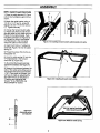
ASSEMBLY
STEP3: Install Forward Clutch Cable
1. Place the cable bracket (R, Figure
2-3) on the handlebar support (A) as
shown.
2. Attach the cable bracket using a
1/4"-20 x 1-1/4" hex hd. screw (S,
Figure 2-3) and 1/4"-20 hex Iocknut
(T). _ghten securely.
3. Unwrap the forward clutch cable
(U, Figure 2-3) from around the engine and slide the thin cable wire into
the .slot in the cable bracket. Push
the cable connector (V, Figure 2-3)
up through the hole in the bracket
until the groove in the connector
snaps into place on the bracket.
Figure 2-3: Installing forward clutch cable bracket and cable.
4. Insert the #10-24 x 2" slotted hd.
screw (W, Figure 2-4) into the cable
spring (X).
5. Thread the screw (W) into the cable'adjuster (Y). '
6. Hook the cable spring (X) into the
"V"-shaped bend in the forward
clutch bail (Z, Figure 2-5).
7. Uft and hold the forward clutch bail
against the handlebar. See Figure 2-6.
8. Measure the distance between the
coils of the cable spring (Figure 2-6).
The length should be approximately
1-7/8". If the length is incorrect, you
will have to make an adjustment to
the cable tension as described in
"Checking and Adjusting Belt
Tension" in the "SERVICE and
ADJUSTMENTS" section.
Figure 2-5: Installing forward clutch cable.
Figure 2-4:
Assemble spring
and adjuster.
Figure 2-6: Measure cable spring.
9
ASSEMBLY
STEP4: CheckLevel of Transmission GearOil
The transmission was filled with
gear oil prior to being shipped.
However, you should check the gear
oil level to make certain it is correct.
AA
1. With the tiller on level ground,
pull the Depth Regulator Lever (AA,
Figure 2-7) back and then all the
way up until the lowest notch in the
fever is engaged.
2. Remove the gear oil fill plug (BB,
Figure 2-8) from the transmission
housing and look into the filler hole.
3. Looking down inside the hole, you
will notice there is a drive shaft on
one side of the hole. If the gear oil
. level is correct, the gear oil should
be approximately half way up the
sides of the drive shaft.
Figure 2-7: Adjust Depth Regulator
Lever.
4. If the gear oil level is low, add
gear oil by referring to "Checking
Transmission Gear Oil" in the
"CUSTOMER RESPONSIBILITIES"
section. Do not operate tiller if
gear oil level is low. Severe damage to transmission
will result.
NOTE: Do not use automatic transmission fluid or engine oil in the
transmission.
Figure 2-8: Remove gear oll fill plug.
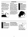
STEP5: CheckHardware
for Tightness
STEP 6: After Assembling and
Before Using Unit
Check all nuts and screws for tightness.
• Read this entire Owner's Manual
for proper safety, operation and
maintenance information.
• Make sure spark plug wire is connected to spark plug before starting
the unit.
IMPORTANT: Motor oil must be
added to the engine crankcase
before starting the engine. Oil filling
instructions are covered in the
"OPERATION" section.
CAUTION
Unit is shipped without oil in
engine crankcase. DO NOT
start engine until oil has been
added. Severe engine damage
will result if this instruction is
not followed. See "Operation"
Section of this manual for oil
filling procedure.
10
OPERATION
KNOWYOURTILLER
READ THIS OWNER'S MANUAL AND ALL SAFETY RULES BEFORE OPERATING THIS EQUIPMENT. Know the
location and function of all features and controls on the equipment. Save this manual for future reference.
MEETS ANSI B71.8 1996 SAFETY STANDARD
This machine meets voluntary safety
standard B71.8- 1996, which is
sponsored by the Outdoor Power
Equipment Institute, Inc., and is published by the American National
Standards Institute, Inc.
OperatingSymbols
Various symbols are used on the tillerto
indicate control settings(your model
may not have all of the symbols).
These symbols are shown below with a
description of their meaning.
I,,
b
LOCATION
ANDUSEOFCONTROLS
WheelDrivePins
These two pins (one on each
side of the wheel shaft), secure the
wheels to the wheel shaft and can
be positioned by you to put the
wheels in either a WHEEL DRIVE
or a FREEWHEEL mode.
Before starting the engine, put
both wheels in the WHEEL DRIVE
position by inserting the Wheel
Drive Pins through the holes in
both the wheel shaft and wheel
hub on both sides of the tiller (see
instructions on next page). This
"locks" the wheels to the wheel
shaft, causing the wheels to turn
when you engage the Forward
Clutch Bail,
Use the FREEWHEEL position
only when the engine is off. This
position lets you easily push or pull
FAST
SLOW
the tiller. To use the FREEWHEEL
mode, place the Wheel Drive Pins
through the holes in the wheel
shaft only (see instructions on
next page), This keeps the wheels
on the shaft, thus allowing the
wheels to rotate freely when you
push or pull the tiller handlebar.
WARNING
Never let either of the wheels
be in FREEWHEEL position
when the engine is running.
Always put bothwheels in the
WHEELORIVEposition before
starting the engine,
Failure to complycouldcause
loss of tiller control, property
damage, or personalinjury.
CHOKE
ENGINE ENGINE ENGINE
STOP
START
RUN
E
STOP
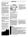
Figure 3-1: A- Wheel Drive Pins; B- Forward Clutch Bail; C- Depth Regula'tor Lever; D- Anti-Reverse Stake; E- Handlebar Height Adjustment;
F- Engine Throttle Lever; G- Engine Choke Lever; H- Engine Recoil Starter.
11
OPERATION
To Place Wheels in WHEELDRIVE
PoSition
1, The engine must be shut off
and cool. Disconnect spark plug
wire and move it away from the
spark plug.
2. Raise one wheel off the ground
and place a sturdy support under the
transmission.
3. Remove the hair pin cotter from
the wheel drive pin and pull out the
wheel drive pin.
WARNING
Do not place tiller on its side
when changing wheel drive
positions or gasoline could
leak from the fuel tank.
Failure to follow this instruction could result in personal
injury or propertydamage,
Wheel Drive Pin
4. Slide the wheel outward and align
the holes in the wheel hub and
wheel shaft, insert the wheel drive
pin through these holes (see Figure
3-2). Insert the straight leg of the
hair pin cotter into the hole in the
wheel drive pin as far as it will go.
Insert the straight leg of the hair pin
cotter into the wheel drive pin'as far
as it will go. See Figure 3-3.
4. Repeat Steps 1-through-3 for the
other wheel. Remove the support
beneath the transmission.
5. Repeat the above steps for the
other wheel, then remove the support under the transmission.
To PlaceWheels in FREEWHEEL
Position
1. Follow steps 1-through-3 of "To
Place Wheels in WHEEL DRIVE Position."
2. Slide wheel inward on wheel
shaft as far as possible.
3. Insert wheel drive pin only
through the hole in the wheel shaft.
-.
Wheel Drive Pin_
I
Hub_
Nub__@
w,oo,
Wheel Shaft
Hair Pin
Cotter
k_. _ .L"_-..(¢'_
Hair Pin ._......_._=.__
Cotter --
= _,aL_ _
Figure 3-2: WHEELDRIVE position.
ForwardClutchBail
The Forward Clutch Bail (Figure
3-4) is used to engage or disengage
(stop) the tiller wheels and tines.
WARNING
Before starting the engine, be
sure that bothwheels are in the
WHEEL DRIVE position. Bee
"Wheel Drive Pins" for instructions.
Failure to comply could result
in loss of tiller control,personal
In]uryor propertydamage.
Rgura 3-3: FREEWHEEL poslUon.
Operate the Forward Clutch Bail as
described below:
1. Put the wheels in the WHEEL
DRIVE position.
2. Rest one hand, palm down, on
top of the handlebar.
3. Use the other hand to lift up and
hold the Forward Clutch Bail. See
Figure 3-4. When the bail is in this
position, the wheels and tines will turn.
NOTE: The wheels will rotate in a forward direction; the tines will rotate
counter-clockwise (backward toward
the operator).
4. To stop motion of the wheels and
tines, release the Forward Clutch
Bail.
12
Rgura 3.4: Operating the Forward
Clutch Ball.
OPERATION
DepthRegulator Lever
Anti-Reverse Stake
This lever controls the depth that
the tines penetrate the soil (see Figure 3-5). Adjust the lever to change
tilling depth by pulling back on it and
moving the lever up (for deeper tilling) or down (for shallower tilling).
This stake is located at the rear of
the transmission, under the tine hood
(see Figure 3-6). Its purpose is to
automatically help prevent the
counter-rotating tines from letting the
tiller back up in the direction of the
operator if the tiller wheels had been
inadvertently left in the FREEWHEEL position. In this situation,
the Anti-Reverse Stake will be forced
down into the ground, lifting the tines
upward out of the soil and helping
prevent backward motion of the tiller.
To'place the tines in the "travel"
position, move the lever down to the
highest notch. This raises the tines
above the ground and allows the
tiller to be moved without tilling.
Travel
Position
Settings_
Deep
Settings
WARNING
Engaging the tines when the
wheels are in FREEWHEELposition can cause the tiller to
move backwardsuddenlyin the
direction of the operator. Before engaging the tines, the
wheels must always be in
WHEELDRIVE position.
Failuretodosocancausepersonal injuryorproperty
damage.
The Anti-Reverse Stake requires
no adjustment, but should be inspected before each tiller use to verify that it swivels freely. Remove any
clogged materials (dirt, roots, rocks,
etc.) that prevent the anti-reverse
stake from swinging freely.
Figure 3-5: Depth Regulator Lever.
Figure 3-6: Arrow points to AntiReverse Stake.
WARNING
Handlebar HeightAdjustment
Before adjusting handlebar
height, shut off the engine, let
it cool down, let all moving
p'artsstop completely,then disconnectthe spark plug wire and
move it away from the spark
plug.
You can adjust the tiller handlebar
height to any of three different positions. (See Figure 3-7.) As a general guide, adjust the handlebars so
they are at waist level when the tines
are about 3"-to-4" down into the soil.
Failuretodo socancausepersonal injuryorpropertydamage.
Figure 3°7: Handlebar adjustment
holes offer three height settings.
13
OPERATION
ENGINECONTROLS
WARNING
Release the ForwardClutchBail
before movingthe EngineThrottle Lever.
Failure to complycould result in
personal injury or property
damage.
tings: FULL CHOKE, PARTIAL
CHOKE and NO CHOKE.
F) Engine Throttle Lever
Adjust this lever (see A, Figure 38) to start and stop the engine and to
regulate engine speed.
• To increase engine speed, move
the lever upward to FAST (Rabbit
symbol) position.
• To decrease engine speed, move
the lever down toward SLOW (Turtle
symbol) position.
Detailed instructions for using the
Choke Lever are provided in this
section.
H) EngineRecoil Starter
The Engine Recoil Starter (refer
to Figure 3-9) is used to start the
engine.
• To stop the engine, move
the lever all the way down
to STOP position.
• To start the engine, move
the lever to the FAST (Rabbit symbol) position.
G)EngineChokeLever
Figure 3-8: Engine Throttle Lever ("A")
adjusts engine speed. Engine Choke
Lever ("B") Is used to assist starting
when engine is cold.
Pre-Start Checklist
Move the tiller to a level area,
then make the following checks and
perform the following services before
starting the engine.
The Choke Lever (B,
Figure 3-8) allows a richer
air/gasoline mixture (more
gasoline) to enter the engine cylinder to make starting a cold engine easier.
The lever has three setFigure 3-9: The Engine Recoil Starter rope Is used
to start the engine.
Use fresh, clean, unleaded fuel.
Fuel goes stale if stored for more
than six months. Do Not Mix Oil
With Gasoline!
9. Put Depth Regulator Lever in the
"travel" position.
1. Disconnect spark plug wire.
10. Reconnect spark plug wire.
2. Add motor oil to engine. (Refer to
.instructions on next page.)
3, Check the air cleaner. It must be
securely assembled and clean.
4. Check safety guards. All guards
and covers must be fastened securely in place.
5. Check engine cooling system.
The cooling fins and air intake
screen must be clear of debris.
6. ,_djust handlebar height.
7. €lleck that the wheels are in the
WHEEL DRIVE position.
8. Put gasoline in the fuel tank. (Refer to instructions on the next page.)
14
OPERATION
BEFORESTARTING
ENGINE
Engine Lubrication
4. Securely replace the oil fill plug.
• Check the oil level before each use
and after every five operating
hours. See Page 21.
The tiller is shipped without oil in the
engine. Permanent engine damage
will result if the engine is run without
oil.
• Change the oil after the first two operating hours and every 10 operating hours thereafter. Change the oil
more often if the machine is operated in extremely dusty or dirty conditions. See Page 21.
1. Only use high quality detergent oil
WithAPI service classification SF,
SG, SH, or SH/CD. Above 32OF, use
SAE 30; below 32OF, use 5W30. DO
NOT USE SAE 10W40 OIL.
NOTE: Although multi-viscosity oils
(5W30, 10W30, etc.) improve starting in cold weather, these oils will result in increased oil consumption
when used above 32OF. Check engine oil more frequently to avoid possible engine damage from running
low on oil.
colder _
32OF...._.
5W30
warmer
SAE 30
2. With the tiller on level ground, pull
the Depth Regulator Lever (Figure 35) back and then all the way up until
the lowest notch in the lever is
engaged. The tines must be in con-
Fill Fuel Tank
The engine must be off and cool before removing the fuel fill cap (Figure
3-11).
Clean area around fuel fill cap and
then remove fill cap. Fill gas tank
with clean, fresh unleaded gasoline.
Do not mix oil with gasoline.
Using a funnel or spout, fill tank to
within 1/2" below the bottom of the
fuel tank filler neck to prevent spills
and to allow for fuel expansion.
install the fill cap securely and wipe
up any spilled gasoline.
Fuel Fill Cap
Figure 3-10: Add motor oll to the engine using the oil fill hole.
tact with the ground-- move the antireverse stake back out of the way to
allow the tines to rest on the ground.
3. Unscrew the engine oil fill plug
(D, Figure 3-10). Using a clean funnel, slowly add oil until the oil level
reaches the overflow point in the oil
fill tube. ALWAYS MAINTAIN THE
OIL LEVEL AT THE OVERFLOW
POINT.
IMPORTANT: Experience indicates
that alcohol-blended fuels (gasohol or
using ethanol or methanol) can attract
moisture which leads to separation
and formation of acids during storage.
Acidic gas can damage the fuel system of an engine while in storage. To
avoid problems, the fuel system
should be emptied before storage for
30 days or longer. Drain the gas
tank, start the engine and let it run until the fuel lines and carburetor are
empty. Use fresh fuel next season.
See STORAGE instructions for additional information. Never use engine
or carburetor cleaner products in the
fuel tank or permanent damage may
occur.
DANGER
Gasoline is highly flammable and its vapors are explosive. Follow these
safety practicesto preventinjury from fire or explosion:
• Never fill tank if engine is runningor hot from use. Let engine and muffler
cool downbefore refueling.
• Do not permitopenflames, sparks,matchesor smokingin fueling area.
• Fill fuel tank outdoorsin a well-ventilated area. Wipe up any fuel spills
and move tiller away from fumesbefore startingthe engine.
• Use onlyan approvedfuel containerand lock it safely away from children.
• Store fuel and the tiller in a well-ventilated area. Do not store fuel or tiller
where fuel vaporsmay reach an openflame or spark, or an ignitionsource
(a hot water heater, furnace, clothesdryer, electric motor,or the like).
• Let engine cool betore storing.
Figure 3.11: Fill the fuel tank.
15
OPERATION
Stopping the Engine
1. Release the Forward Clutch Bail
to stop the wheels and tines from
turning.
2. Move Engine Throttle Lever to
STOP position to stop the engine.
Startingthe Engine
1. Do not engage (hold) the Forward
Clutch Bail against the handlebar
when starting engine.
2. Both wheels must be in the
WHEEL DRIVE position (see Figure
3-2).
3; Mov_ the Choke Lever to the
FULL CHOKE position (move lever
in direction of arrowhead located on
lever). NOTE: If restarting a warm
engine after a short shutdown, move
Choke Lever to NO CHOKE position.
4. Move the Engine Throttle Lever
fully up to fast (Rabbit) position
which is used for starting.
5:_ Place your left hand on the gasoline tank (to avoid hot surfaces) to
stabilize the tiller when starting.
6. Use your right hand to slowly pull
the recoil starter rope (Figure 3-12)
until you feel resistance. Let it
rewind. Then rapidly pull the starter
rope outward. (First check for any
obstacles behind you.) Repeat until
the engine starts.
Guiding the Tiller
When tilling, relax and let the tiller
move along at its own speed. Do
not push the tiller to make it move
WARNING
Always place both wheels in
the WHEELORIVE position before startingthe engine.
Never have the wheels in the
FREEWHEELposition when the
engine is running. When the
wheels are in FREEWHEEL,
they do not hold backthe tiller,
and the tines could propel the
tiller backwardrapidly.
Failure to comply could result
in serious personal injury or
propertydamage.
7. Once the engine is running, gradually move the Choke Lever to the NO
CHOKE position. If engine falters,
move Choke Lever to 1/2 Choke until
engine runs smoothly, then to NO
CHOKE position.
Figure 3-12: Pull Recoil Start Rope
out rapidly to start engine.
DANGER
NOTE: If engine fails to start after
three pulls, move Choke Lever to NO
CHOKE position and pull starter rope
again.
Do not run engine indoors. Engine exhaust contains carbon
monoxide, o deadlygas that is
colorless,
odorless
and
tasteless.
"
NOTE: If engine fires, but does not
continue to run, move Choke Lever to
FULL CHOKE and repeat steps 4, 5
and 6 until engine starts.
Failure to follow this instruction couldresult in serious personal injury or properly
damage.
8. Move the Engine Throttle Lever to
the positionthat provides the desired
engine speed.
faster. Do not push down on the
handlebars to make the tines dig
more deeply.
Walk beside the tiller on the untilled side. Use one hand, yet keep a
firm hand grip on the handlebar
(while keeping your arm loose) to
guide the tiller. Walking alongside
keeps you from disturbing the newly
tilled soil and replanting any weed
seeds which the tines might have
brought up to the surface. It is also
easier to control the tiller in hard or
rocky soil if you walk beside it guiding it with one hand (instead of walking behind the tiller, controlling it with
two hands).
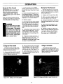
Figure3.13:
TIIIIngWlthJustOne
Hand Is recommended.
16
Tilling Depths
This is a CRT (counter-rotating tine)
tiller. As the wheels pull forward, the
tines rotate backward. This creates
an "uppercut" tine action which digs
deeply, uprooting soil and weeds.
Don't overload the engine, but dig as
deeply as possible on each pass.
On later passes, the wheels may
tend to spin in the soft dirt. Help
them along by lifting slightly on the
handlebar. (Using just one hand,
palm upward, works most easily.)
When cultivating between rows,
use a shallow Depth Regulator Lever
setting. This will get rid of in-row
weeds, but prevent the tines from
digging deeply enough to damage
plant roots.
OPERATION
Moving the Tiller Forward
IMPORTANT: Before you begin tilling, move the tiller to a safe, level
area and practice maneuvering
without actually tilling. Keep the
Depth Regulator Lever in the "travel"
position.
After you become familiar with the
handling of your tiller, you can move
it into the garden and begin tilling.
WARNING
Do not push down on the handlebars to try to make the tiller
till more deeply. This prevents
the wheels from controlling
tiller speed and can allow the
tines to rapidly propel the tiller
backward, which could result in
loss of control, property damage, or personal injury.
Turningthe Tiller Around
Practice turning your tiller in an
open, level area until you feel comfortable with the procedure.
1. As you near the end of a row, lift
the handlebar so the tines clear the
ground. Refer to Figure 3-14.
1. Put the wheels in the WHEEL
DRIVE position (wheel pins must be
through the wheel hubs and the axle
holes).
2. Move the Depth Regulator Lever
to the desired position. Check that
the Anti-Reverse Stake swivels freely
back and forth- remove any clogged
material on or around the stake.
3. Start the engine.
4. For forward motion of the wheels
and tines, lift and hold the Forward
Clutch Bail against the handlebars.
The wheels and tines will rotate as
long as the bail is held in this position.
5. As the tiller moves forward, let the
wheels pull the tiller along. Do not
push the tiller to make it go faster.
Allow the tiller to move along at its
own speed.
Moving the Tiller Rearward
The tiller weighs only 117 pounds,
so it is quite easily maneuvered rearward for _
distances by using the
following procedure:
1. Release the Forward Clutch Bail.
2. 131tthe handlebar slightly upward
until the tLnes are out of the soil.
3. Swing the handlebar to the left so
the right wheel takes a "step" toward
the rear.
4. Now move the handlebar to the
right so the left wheel takes a step
backward.
5. Repeat to "walk" your tiller rearward. If longer distances need to be
covered in reverse, shut off the engine, then move the wheel pins so
the wheels are in FREEWHEEL.
6. To stop the wheels and tines, release the Forward 'Clutch Bail. The
engine wLIIcontinue to run until
stopped by moving the Engine Throttle Lever to the STOP position.
2. As you come out of a row, swing
the handlebars to the side, pivoting
the tiller 180 °, so you can line up
with the next row. See Figure 3-15.
3. As the tiller enters the next row,
lower the handlebar slowly until the
tines start to till.
Tilling in the Garden
The following pages provide
suggestions for using the tiller in the
garden. You can design your garden
layout to obtain the most beneficial
use from your tiller.
Figure 3-15: Lining up the tiller to enter the next row.
Figure 3-14: Exiting a row in the garden.
17
OPERATION
SeedbedPreparation
Cultivating
AvoidMaking Footprints
Pdor to planting, be sure the soil
is as loose and finely textured as
possible. About two or three weeks
before planting, till the garden two or
three times. Then, till once more
before planting.
When planning your garden, keep
in mind that the tiller has a tilling
width of approximately 14". Allow at
least this width between rows in your
garden-- plus additional width for
plant growth. Take into account that
bushy plants like beans and tomatoes need more width.
When tilling, always try to walk
alongside the tiller on the side that is
yet to be tilled. This prevents replanting weed seeds and leaves a
nicer appearance.
When preparing the soil, till a
fresh path on each pass rather than
overlapping. This gives the wheels
maximum traction on undisturbed
soil. See Figure 3-15. Dig as deeply
as possible on each pass without
overloading the engine. Later passes can be overlapped. After going
up and down the rows in one direction, make a second pass at a right
angle across your earlier rows, See
Figure 3-16. In very hard ground,
additional passes may be needed.
Don't till when the soil is too wet.
This produces large clumps which
later dry out and become hard. If the
soil compresses easily into a ball, it
is still too wet to be tilled.
When cultivating, use a shallow
Depth Regulator Lever setting. Do
not cultivate deeper than 1"-or-2".
Shallow cultivating keeps weed
growth to a minimum and doesn't
damage plant roots.
For best results, begin cultivating
as soon as seedlings appear, and
then cultivate as often as once a
week. The day after a light rain is an
excellent time to cultivate, as long as
the plants are dry. Avoid working in
the garden when plants are wet.
Diseases, blight, and rust can be
easily spread among wet plants with
your hands, clothing or even the
tiller.
_d
°1
l
i=
•
•
•
Figure 3-16: Second tilling pattern.
Figure 3-15: Initial tilling pattern.
18
OPERATION
Preventing Tines From
BecomingTangled
...When tilling, you may find that the
tines.become tangled with material
(tall vegetation, long grass, tough
vines, etc.).
WARNING
Before removing any debris
from the tines, stop the engine,
allow it to cool, disconnectthe
spark plug wire and move it
away from the spark plug.
Failure to do so could result in
personal injury or property
damage.
Tohelp preventtangling:
1. While tilling, swing the handlebars from side-to-side about 6"-to12". This "fishtailing" action will often
dislodge any debris.
2. Always use the deepest Depth
Regulator Lever setting possible
(without making the tiller jump or
buck upward).
3. "1311
under cover crops and crop
residues while they are still green.
'4. Shred or chop up any tall, tough,
or stringy organic matter before tilling it into the soil.
5. You may have to mow or cut vegetation before power composting.
6. If the tines are heavily tangled,
stop the engine and disconnect the
spark plug wire. Then, cut away any
debris.
Tilligg.,onSlopes
Plant your garden preferably on
flat ground, but certainly on no more
than a moderate slope. Do not operate the tiller on a slope that is too
steep for safe operation.
Plant garden rows vertically on a
slope (up and down the slope). This
lets you use the entire area for a
seedbed and leaves enough room
between the rows for cultivation.
You lose these benefits if you garden
on areas styled like terraces.
WARNING
CAUTION
Do not operatethe tiller on a
slope too steep for safe operation, Till slowly and be sure
that you have goodfooting.
Loadingand unloadinga tiller
into or from a vehicle is potentially hazardous. We.do,
not recommendthat you do so
unless absolutely necessary
because this could result in
personal injury or property
damage.
Failure to do so could result
in personal injury or property
damage.
If you put enough organic material
into the soil to improve its waterholding capabilities, you should not
have a problem with soil erosion.
NOTE: On a slope, the oil level in
the tiller engine slants toward the
downhill side of the engine. Some
internal parts may not get enough
oil. To prevent this, make sure that
the engine oil level is full to the point
of overflowing from the oil check
tube before starting to till. Also
check the oil level every thirty minutes while you're tilling on a slope.
Tiller Loadingand Unloading
• Shut the tiller engine off before
loading or unloading. Let engine
cool, disconnect spark plug wire and
prevent wire from touching the plug.
• The tiller is too heavy (over 115
Ibs.) to be safely lifted by one person. If you do lift the tiller, two or
more people should share the load.
• We recommend that you use sturdy ramps and that you manually roll
the tiller into or out of the vehicle
(tiller engine must be off). This requires the assistance of another.
• Ramps should be strong enough
to support the tiller and those moving
it. The ramps shouLd provide good
traction and have side rails to guide
the tiller up and down; they should
have a locking device to secure
them to the vehicle bed.
• The operator and handlers should
wear sturdy footwear that grips well.
• Position the vehicle so the ramp
angle is as flat as possible. Turn the
vehicle engine off and apply the vehicle parking brake.
19
If loading or unloading must
be undertaken, use the following guidelines to assist
you,
• When going UP ramps, stand in
the normal operating position and
push the tiller ahead of you. Position
a person at each wheel to help.
• When going DOWN ramps, carefully walk backward down the ramps
with the tiller following you. Position
a person at each wheel to control the
speed of the tiller.
• Have wood blocks handy to place
on the downhill sides of the wheels if
you need to stop the tiller from rolling
down the ramps. Use the blocks to
temporarily keep the tiller in place on
the ramps while you get a firmer grip
on the handlebars, etc. Also use
blocks to keep the wheels in place
after tying down the tiller.
• After positioning the tiller in the
vehicle, be sure both wheels are engaged in the WHEEL DRIVE position
to prevent the tiller from moving.
Then securely tie down the tiller.
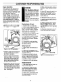
CUSTOMER
RESPONSIBILITIES
grease to the wheel shaft. This
makes future wheel removal easy.
REQUIRED
MAINTENANCE
SCHEDULE
REQUIREDMAINTENANCE
Before Every Every Every
As
Each
10
30
50
Noted
Use Hours Hours Hours
2. Depth Regulator Lever
"
Clean and grease the back, front
and sides (refer to "2", Figure 4-1 ).
Tiller Lubrication
CheckEngine0il Level"EngineLubrication"
ChangingEngine0il
•
1
•
2
Checking Transmission Gear0il Level
•
4
Air cleaner Maintenance
•
5
EngineCooling System Maintenance
Spark Plug Maintenance
TightenTillerHardware
•
Check Tines for Wear
Checking/Adjusting BeltTension
3
•
•
Checkfrequentlyduringfirst 2 hoursof newoperation;thereafterevery5 hours.
Changeafter 2 initialoperatinghours;thereafterevery10 hours.
Checkafter2 initialoperatinghours;thereafterevery10 hours.
Checkafter2 initialoperatinghours;thereafterevery30 hours.
Replacemoreoften if usedin extremelydustyor dirty conditions
GENERALRECOMMENDATIONS
Tiller Lubrication
The Warranty on this machine does
not cover items that have been subjected to operator abuse or negligence. To receive full value from the
warranty, the operator must maintain
the machine as instructed inthis manual.
Refer to Figure 4-1 and Figure 4-2 for
lubrication points on your tiller.
Some adjustments will need to be
made periodically to properly maintain your machine.
Keep the air filters clean and change
the spark plug annually. A clean air
filter system and new spark plug help
the engine run better and last longer.
1. Wheel Shaft
Remove the wheels and use a clean
rag to wipe off old grease from the
wheel shaft ("1", Figure 4-1). Inspect
the shaft and use fine sandpaper to
remove any rust or burrs. Apply new
Because the tiller is operated in the
garden, frequently under hot and
dirty conditions, regular maintenance
is very important to ensure that you
are getting proper performance from
your tiller. There are several maintenance procedures that will hetp keep
your tiller in good operating condition:
NOTE: When you oil the pivot points
on the shifting mechanism, be sure
that you do not get any oil on either
the belt or the pulleys. Otherwise,
the belt could slip and would be unable to transfer engine power to the
transmission.
Figure 4-2: Lubrication points on
shifting mechanism,
2
• ,. Change engine oil regularly.
• 'Lubricate the controls when needed.
Keep the correct tension on the
forward drive belt.
• Replace the engine air cleaner
element when dirty.
• Keep engine cooling fins clean.
5. Shifting Mechanism
Carefully oil all pivot points on the
shifting mechanism ("5", Figure 4-2),
Use common lubricating oil (#30
weight motor oil is acceptable) at the
oil points. Use a good quality grease
(preferably with a metal lubricant additive) at the grease points.
Regular,Maintenance
•
4. Tine Shaft
Remove the tine holder assemblies
and clean any rust or burrs from the
shaft ("4", Figure 4-1) with a fine
sandpaper. Liberally apply grease to
the tine shaft.
3
CheckAnti-Reverse Stake
NOTEt NOTE2 NOTE3 NOTE4 NOTE5 -
3. HandlebarSupportBolls
Oil the threads on both handlebar
support bolts ("3", Figure 4-1).
Figure 4-1: Tiller lubricaUon points.
2O
CUSTOMER
EngineLubrication
Only use high quality detergent oil
with API service classification SF,
SG, SH, or SH/CD. Above 32OF, use
SAE 30; below 32OF, use 5W30. DO
NOT USE SAE 10W40 OIL.
NOTE: Although multi-viscosity oils
(5W30, 10W30, etc.) improve starting in cold weather, these oils will resuit in increased oil consumption
when used above 32OF. Check engine oil more frequently to avoid possible engine damage from running
low on oil.
RESPONSIBILITIES
WARNING
Stop the engine, allow it to
cool, disconnectthe spark plug
wire and prevent it from touching the spark plug before
changingthe engine oil. Do not
touch any engine parts which
may be hot.
Failure to do so could result in
personal injury or property
damage.
CheckingEngineOil Level:
colder-,ll-----...--
32OF_
warmer
1. Move the tiller to a level area.
"_ '
5W30
=
SAE 30
2. Pull the Depth Regulator Lever all
the way up until it is in the bottom
notch. The tines must be in contact
with the ground-- move the anti-reverse stake back if necessary.
4. Place a drain pan with a minimum
capacity of 1-quart beneath the drain
plug.
5. Use a 3/8" open end wrench to remove the drain plug (see arrow in
Figure 4-4). Put it aside. Let all of
the old engine oil drain completely
into the drain pan.
6. Reinstall the drain plug securely.
7. Remove the wood board from beneath the wheel.
8. Refill the engine with the correct
type and weight engine oil. Above
32°F, use SAE30 oil; below 32OF,
use SAE 5W30 oil. Do not use SAE
10W40 oil.
,p
3. Unscrew the oil fill plug from right
side of engine (see Figure 4-3).
4. If the oil level is correct, the level
will crest at the top of, or begin to
flow from, the oil fill tube. Reinstall
the oil fill plug.
!_
Jj
C'
0il Fill
Figure 4-3: Off Fill Plug location.
• Check the engine oil level frequently during the first two hours of en'gine break-in operation.
• Check the engine oil level before
starting the engine. When operating the tiller, stop the engine and
check oil level every 5 operating
hours. Keep oil level at the overflow point in the oil fill hole.
o Change the oil after the first two operating hours and every 10 operating hours thereafter. Change the oil
more often if the machine is operated in extremely dusty or dirty conditions. See Page 21.
5. If the level of the oil was below
the very top of the fill tube, oil must
be added as follows.
AddingEngineOil:
1. Insert a clean funnel into the oil
fill hole.
2. Above 32°F, use SAE30 oil; below 32Ol, use SAE 5W30 oil. Do not
use SAE 10W40 oil
3. Slowly pour oil into the funnel.
Check the oil level frequently while
pouring. (Remove the funnel when
checking.) When the oil just begins
to overflow, the level is correct.
4. Replace the oil fill plug securely.
Changing Engine Oil
1. Start engine and let it warm up,
Then turn the engine off.
2. There are two engine oil drain
plugs on either side of the engine
base. Use whichever one is most
conveniently located for you.
3. Place a 2"x 4" wood board under
the wheel opposite the drain plug
you'll be removing.
21
,
9. Check the oil level to be sure it is
correct before starting the engine.
ain Plug
Figure 4-4: Draining engine oil.
CUSTOMER
RESPONSIBILITIES
Checkingand Topping-Off
Transmission
GearOil
DANGER
Gasoline is highly flammable
and its vapors are explosive.
Follow these safety practices
to prevent persona[ injury or
property damage from fire or
explosion.
Checking Transmission Gear Oil:
'1. Move the tiller to a level area.
2. Pull the Depth Regulator Lever
up.
3, Unscrew ihe filler/check plug
from the top of the transmission (it
is located just behind the belt cover).
4. Use a flashlight to look down into
the filler/check plug hole. See Figure 4-5. Note the drive shaft on
one side of the hole. If the gear oil
level is correct, it should be halfway
up the sides of the drive shaft. If
topping off is needed, follow the
instructions below.
• Allow the engine and muffler to cool for at least two
minutes before draining the
tiller's gasolinetank.
• Do not allow open flames,
sparks, matches or smoking
in the area.
Figure 4-6: Gear oil fill hole.
i,
3. Slowly pour clean gear oil into
the transmission. Frequently
check the level so as not to overfill
the transmission. See Figure 4-6.
4. When gear oil level is correct,
reinstall filler/check plug securely.
ChangingTransmissionOil
The transmission gear oil does
not have to be changed unless you
know that it has been contaminated by foreign materials such as
sand, dirt, or metal particles. Of
course, any internal repairs on the
transmission would also require
that the gear oil be drained and
changed.
Figure 4-5: Checking the transmission gear oil level
Toppingoff Transmission
Gear Oil
,1. Complete steps 1-through-3 described in "Checking Transmission
Gear Oil."
2. Insert a funnel into the
filler/check plug hole.
• Wipe away spills and push
tiller away from spilled fuel.
• Use only an approved fuel
container and store it safely
out of the reach of children.
• Do not store gasoline in an
area where its vapors could
reach an openflame or spark,
or where ignition sourcesare
present (such as hot water
and space heaters, furnaces,
clothes dryers, stoves, electric motors, etc.)
1, Drain gasoline from the fuel
tank or run the engine until the fuel
tank is empty.
2. Drain the oil from the engine.
3. Remove the four screws securing the transmission cover to the
front part of the transmission. Lift
the cover and gasket off the transmission. See Figure 4-7.
4. Remove the left wheel.
NOTE: When adding only a few
ounces of gear oil, use API rated
GL-4 or GL-5 transmission gear oil
with a viscosity of SAE 140, SAE
85W-140, or SAE 80W-90. When
adding a complete refill of new
gear oil after having drained the
transmission, refill only with
SAE 140 or SAE 85W-140 with
an API of GL-4.
5. Lower the left axle down into a
drain pan and slowly tilt the tiller to
the left so the gear oil drains from
the top of the transmission into the
drain pan. See Figure 4-8.
NOTE: Do not use automatic
transmission fluid or engine oil in
the transmission.
8. Add new gear oil--see
cations in NOTE at left.
Figure 4.7: Remove four screws to
remove transmission cover.
6. Once gear oil has drained, tilt
tiller upright and reinstall wheel.
7. Reinstall the transmission cover
using a new cover gasket.
specifi-
9. Add engine oil to the engine.
Figure 4-8: Draining the gear oil.
22
CUSTOMER
RESPONSIBILITIES
Checkingfor Oil Leaks
Air Cleaner Maintenance
Regularly check your tiller for oil
leaks from the engine and the
transmission. Slight seepage is no
cause for major concern. However, if your tiller is losing a lot of
oil, do not use it until it's repaired.
Your tiller's engine is equipped
with a replaceable dry paper filter.
Replace this filter every 30 operating hours or at least once a year,
and even more frequently under
dusty or dirty operating conditions.
Inspect the area where you park
your tiller for stains on the floor
which would indicate a leak. If you
find a leak, first tighten any bolts or
screws which may have loosened
up.
Do not attempt to clean this filter. Simply replace it when dirty.
If you are unsure how much oil
has been lost from the tiller, check
the oil levels before operation.
Also, when operating your tiller,
frequently check the oil levels to be
sure that engine oil and transmission gear oil levels don't become
too low for safe operation.
If you have further problems
with oil leaks, contact your Sears
Service Center for assistance.
4. Turn the cover slightly clockwise and tighten the two screws.
To Remove Paper Air Filter:
1. Loosen the two screws that secure the air cleaner cover to the
base of the air cleaner.
2. Slightly turn the cover counterclockwise. Remove the cover and
the paper air filter.
oo
_<
To Change the Paper Air Filter:
oo
o
_----_Air Filter
1. Thoroughly clean the base of
the air cleaner and the inside of
the air cleaner cover.
2. Place the new paper filter in the
cover.
EngineCoolingSystem
Maintenance
Engine Ignition System
Maintenance
Frequently inspect the engine
cooling fins, shrouds, and throttle
linkage for a build-up of dirt, dried
weeds, grease, etc.
Your tiller's engine has a dependable, maintenance-free electronic ignition system. The system
has no condenser or points. This
means you do not have to tune up
the engine. The only ignition system maintenance required is periodic changing of the spark plug.
(See the following spark plug instructions.)
Always keep these areas free
from debris to keep air currents
flowing freely. See arrows in Figure 4-10.
:
3. Place the cover (with filter inside it) on the base of the air
cleaner. Align the two screw holes
in the cover with the two screws in
the base of the air cleaner. Refer
to Figure 4-9.
Figure 4-9: Engine Air Filter.
3. Use a 13/16" spark plug socket
to remove the spark plug. The
plug may be cleaned (do not sandblast or wire-brush it), and the gap
set at .030" or a new spark plug
may be used instead.
4. Install a new plug if the old
plug's electrodes are pitted or
burned or if the porcelain is
cracked. For replacement use
Champion RJ-17LM only.
NOTE: A resistor spark plug must
be used for replacement.
Spark PlugMaintenance
Check the spark plug at the beginning or the end of each season,
or every 30 operating hours.
Clean the area around the spark
plug hole before removing the
spark plug.
1. Stop the engine, and wait for all
moving parts to stop completely.
Figure 4-10: Keep these areas free
of debris.
2. Disconnect the spark plug wire
from the spark plug.
23
Carburetor Adjustments
Your carburetor has been preset for best tiller performance. If
your carburetor may need adjustment, contact your nearest Sears
Service Center.
SERVICE AND ADJUSTMENTS
WARNING
Stop the engine, allow it to
cool, disconnectthe spark plug
wire and prevent it from touching the spark plug before tightening any bolts, screws, or
nuts.
c
Failure to do so could result in
personal injury or property
damage.
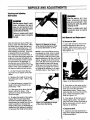
TighteningTiller Hardware
After the first two hours of tiller operation, check all fasteners (nuts,
bolts, screws, pins, etc.) and tighten
any that may have loosened. After
this initial check, check those same
fasteners after every ten hours of
tiller operation.
Most of the fasteners on your tiller
are in plain view. However, the following ones are not readily visible.
Be sure to check them for tightness
as well.
1. Rear End Cap Bolts- These
three bolts are located at the rear
end of the tiller transmission. They
secure the rear cap and the anti-reverse stake. Lift up the hood flap to
view this hardware.
2. Transmission Housing Cover
Bolts- These four bolts are located
on the top of the rear end of the tiller
transmission. You see them when
you lift the hood flap.
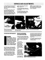
Tines
As you use your tiller, the tines
will gradually wear. They will be-come shorter, narrower and pointed,
decreasing their ability to till effeCtively. Check the tines for wear several times a season, and replace
badly worn tines to restore the tiller's
effectiveness.
NOTE: You must first remove the
tiller hood before removing either a
single tine holder or individual tines.
Remove the two screws at the front
of the hood and the two screws at
the rear of the hood and lift off the
hood. Be sure to replace the hood
securely after changing tines or tine
holders.
aJ
Rgure 4-11
WARNING
This is a CRT (counter-rotating
tine) tiller and its tines mustbe
mounted in the directionshown
in Figure4-11. It mountedwith
curves in the opposite direction, tiller will dig poorly and
be more likely to run backwards.
Failure to comply could result
in personal injury or property
damage.
Removingand Installing
Tine Assemblies
WARNING
Stop the engine, allow it to
cool, disconnectthe spark plug
wire and prevent it from touching the spark plug before removing or installing a tine or a
tine assembly.
Failure to comply could result
in personal injury or property
damage.
1. Use a 9/16" socket, 6" extension,
a ratchet, and a 9/16" box end
wrench to loosen the nut (A, Figure
4-11) and screw (B) that secure the
tine holder to the tine shaft.
2. Use a rubber mallet to tap the
tine holder loose. Slide the tine assembly oft the tine shaft.
24
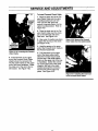
3. Repeat Steps 1 and 2 above to
remove the other tine assembly.
4. Installing the tine assembly is
simply the reverse of its removal.
First be sure to remove any rust, uneven spots or burrs from the tine
shaft using fine sandpaper. Then
grease the tine shaft before reinstalling the tine assemblies. Be sure
all the cutting edges face so they will
enter the soil first when the tiller is
moving forward-this means the cutting edge on the top of each tine faces
toward the operator position.Tighten
the hardware very securely.
Removingand Installing
IndividualTines
1. Use two 9/16" box end wrenches
to remove the two screws (C, Figure
4-11) and nuts (D) that secure the
tine to its tine holder.
NOTE: If the nuts are rusted, apply
penetrating oil to the screw and nut.
Always loosen the nut rather than
the screw.
2. When installing individual tines,
install them in the reverse order from
which they were removed. The two
sets of inboard tines are installed so
one set faces toward the transmission housing and the other faces
away from it. The single outboard
tine set faces toward the transmission housing. Also be sure the cutting edge at the top of each tine
faces toward the operator position.
(See Figure 4-11 .)
SERVICE AND ADJUSTMENTS
Checkingand Adjusting
Belt Tension
WARNING
Stop the engine, let it cool
down, disconnect the spark
plug wire and prevent it from
touching the spark plug before
changingthe belt.
WARNING
Stopthe engine, allow it to cool
down, disconnect the spark
plug wire and prevent it from
touching the spark plug before
checkingthe belt tension.
Failure to comply could result
in personal injury or property
damage.
Failure to comply could result
in personal injury or property
damage.
Belt Removaland Replacement
To Remove the Belt:
After the initial two hours of tiller operation, check the belt tension. After
this initial check, check the belt tension every 10 operating hours. The
same schedule should be followed
after installing a new belt. If the belt
is slipping (the tines and wheels
don't rotate as fast as when new, or
they may even stop turning when the
engine is running at full speed), perform the belt tension check to see if
the belt needs to be tightened. If
you find you can not bring the Forward Clutch Bail al! the way up to the
bottom of the upper handlebar, you
will need to loosen the belt tension.
1. Lift the Forward Clutch Bail up
and hold it to the bottom of the handlebar.
Figure 4-12: Measure the length
of the Clutch Ball Spring to check
for correct belt tension (1-7/8").
NOTE: If you have difficulty turning
the adjuster by hand, have an assistant hold the Forward Clutch Bail to
the handlebar while you insert a flattipped screwdriver into the clutch bail
spdng. Engage the tip of the screwdriver with the slot in the screw head
that is inside the clutch bail spring.
While you turn the screw, keep the
Forward Clutch Cable from turning
by gripping the adjuster on its upper
end with a pliers. See Figure 4-13.
2. Measure the length of the clutch
bail spring with a ruler. Refer to Figure 4-12.
Figure 4-14: Remove belt cover.
3. If the belt tension is correct, the
length of the spring should be approximately 1-7/8".
2. Push down on the upper section
of the belt to create some belt slack
when you move the belt off the
transmission pulley. Reach underneath the tiller and move the belt forward, off the transmission pulley.
Refer to Figure 4-15.
4. If the spring is too short, the belt
tension will be too loose. If the
spring is too long, the belt tension
will be too tight.
5. To adjust the length of the spring,
release the Forward Clutch Bail.
Screw the threaded adjuster counterclockwise (as viewed from the operator's position) to increase the
length of the spring or clockwise (as
viewed from the operator's position)
to decrease the length of the spring.
1. Use a 3/8" wrench to remove the
bolt that attaches the belt cover to
the tiller. Slide the belt cover up the
cable slightly so it is out of the way.
See Figure 4-14.
Figure 4-13: Adjusting the length
of the Clutch Ball Spring.
3. From above, lift the belt up and
off the engine pulley. You need to
_ guide the lower portion of the belt as
you're removing it so that it doesn't
hang up on anything.
ToInstall the Belt:
1. Insert the new belt downward, in
back of the engine pulley and in front
of the transmission.
25
SERVICE AND ADJUSTMENTS
2. Work the belt over the transmission pulley. Make sure the belt
goes in the groove in the transmission pulley.
3. Loop the upper section of the
belt around the engine pulley.
Make sure the belt goes in the
groove in the engine pulley. Also
be sure the belt goes between the
engine pulley and the wire belt
guide on each side of the pulley.
Refer to Figure 4-17.
4. Slide the belt cover down the
Forward Clutch Cable and reinstall
it on the tiller.
NOTE: If you've installed a new
belt, remember to check and readjust its tension after the first two
hours of operation.
5. Check the belt tension. See
"Checking and Adjusting Belt Tension" for specific instructions.
NOTE:
VHEEL REMOVED
FOR CLARITY
Figure 4-15: Moving the belt off
the transmission pulley,
Figure 4-16: Moving the belt off
the engine pulley.
ForwardClutchBailAdjustment
Figure 4-17: The new drive belt installed.
RemovingandInstalling
the ForwardClutchCable
WARNING
ToRemoveForwardClutchCable:
Stop the engine, allow it to
cool, disconnect the spark
plug wire and prevent it from
touching the spark plug before removing or installing
the ForwardClutchCable.
1. Unhook the spring that is on the
upper end of the Forward Clutch
Cable from the Forward Clutch
Bail.
Failure to complycould result
in injury or propertydamage.
See =Checking and Adjusting Belt
Tension" in this section. When the
belt has the correct amount of tension, the Forward Clutch mechanism should be properly adjusted.
If, after adjusting the belt tension, the Forward Clutch mechanism does not operate correctly,
please contact your Sears Service
Center for further assistance.
end wrench to loosen the Iocknut on
the lower end of the Forward Clutch
Cable sheath where it attaches to
the cable mounting bracket (refer to
Figure 4-19).
5. Push the Forward Clutch Cable
forward to free it from the cable
mounting bracket.
2. Use a 3/8"
wrench to remove
the bolt that attaches the belt
cover to the tiller.
Slide the belt cover up the cable
until it is out of the
way.
3. Use a pair of
needle nose pliers to carefully
remove the clip
ring from the clevis pin on the idler
lever (Figure 4-18).
4. Use one 7/16"
and one 3/8" open
Figure 4-18: Removing
26
the clip ring.
SERVICE AND ADJUSTMENTS
To Install Forward Clutch Cable
1. Place the lower end of the Forward Clutch Cable into the cable
mounting bracket and use one
7/16" and one 3/8" open end
wrench to securely fasten it to the
cable mounting bracket. Refer to
Figure 4-21.
2. Place the lower end of the Forward Clutch Cable over the clevis
pin on the left-hand side of the
idler lever. See Figure 4-21.
3. Use a pair of needle nose pliers
to place the clip ring on the clevis
pin (Figure 4-18).
Figure 4-20: Remove the Forward
Clutch Cable from the cable brackeL
4. Hook the spring on the upper
end of the Forward Clutch Cable to
the Forward Clutch Bail.
Figure 4-19: Loosening the Forward
Clutch Cable.
6. Pull downward on the upper
end of the Forward Clutch Cable
sheath where the connector fits
into the cable bracket on the upper
end of the lower handlebar. Guide
the cable out of the slot in the cable bracket. See Figure 4-20.
5. Pull downward on the upper
end of the black cable sheath.
Slide the Forward Clutch Cable
into the slot in the cable bracket
that is on the upper end of the lower handlebar. Center the connector on the upper end of the cable
sheath in the hole in the cable
bracket and push the connector
into the hole until it snaps into
place. See Figure 4-20.
Figure 4-21: Installing the lower end
of the Forward Clutch Cable.
27
'
Tiller Storage
STORAGE
DANGER
Whenever you don't intend to use
your tiller for 30 days or longer, you
should perform the following steps to
ensure that it will start easily and
perform properly when removed
from storage.
Gasolineishighlyflammableand itsvaporsare explosive. Followthesesafety
practicesto preventinjuryor propertydamagefromfire or explosion.
• Thoroughly clean the machine.
• Wipe up spills and pushthe tiller away from spilled fuel.
• Be sure that all nuts, bolts and
screws are securely fastened. Inspect parts for damage, breakage
or wear. Replace as necessary.
• Use onlyan approvedfuel containerand store it safely from children.-
• Let engine and mufflercool at least2 minutes beforedrainingfuel tank.
• Do not allow openflames, sparks, or matches, or permit smokingin fueling area.
. Do not store gasoline in an area where its vaporscould reach an open
flame or spark, or where ignition sourcesare near (such as hot water and
space heaters,furnaces, clothesdryers, stoves, motors, etc.)
• Touch up all rusted or chipped
paint surfaces. Sand lightly before
repainting.
• If possible, store your unit indoors
and cover it with a suitable protective cover (not plastic) that does
not retain moisture.
IMPORTANT: Never cover the unit
while the engine and exhaust areas
are still warm.
• Do not store gasoline from one
season to another.
• Replace your gasoline can if it
starts to rust. Rust and/or dirt in your
gasoline will cause problems.
Engine Storage
NOTE: If "Gasohol" has been used,
run engine until the tank is empty.
Then put 1/2 pint of "Unleaded" regular gasoline into the fuel tank and
again run the engine until tank is
empty.
NOTE: Fuel stabilizer (such as
Craftsman Fuel Stabilizer No.
335500) is an acceptable alternative
in minimizing the formation of fuel
gum deposits during storage. Add
stabilizer to gasoline in fuel tank or
storage container. Always follow the
mix ratio and instructions on the stabilizer container. Run engine at least
10 minutes after adding stabilizer to
allow the stabilizer to reach the carburetor. Do not drain the gas tank
and carburetor if using fuel stabilizer.
Fuel System
IMPORTANT: It is important to prevent gum deposits from forming in
essential fuel system parts such as
carburetor, fuel filter, fuel hose, or
tank during storage. Also, experience indicates that alcohol blended
fuels (called gasohol or using
ethanol or methanol) can attract
moisture which leads to separation
and formation of acids dudng storage. Acidic gas can damage the fuel
system of an engine while in
storage.
EngineOil
Drain oil and replace with clean engine oil. See "Engine Lubrication" in
the CUSTOMER RESPONSIBILITIES section.
• Drain the fuel tank.
• Start the engine and let it run until
the fuel lines and carburetor are
empty.
• Never use engine or carburetor
cleaner products in the fuel tank or
permanent damage may occur.
• Use fresh fuel next season.
28
EngineCylinder
• Remove spark plug. Squirt one (1)
oz. (30ml) of clean engine oil into
spark plug hole.
• Cover spark plug hole with a clean
rag.
• Pull starter rope to crank engine
over, slowly, several times.
• Install spark plug. Do not connect
spark plug wire.
TROUBLESHOOTING
PROBLEM
EngineDoesNotStart.
EngineRunsPoorly.
EngineOverheats.
CORRECTION
POSSIBLE CAUSE
1. Sparkplugwiredisconnected.
1, Reconnectwire.
2. Fueltankempty.
2. Addgasoline.
3. Stalegasoline.
3. Draingasoline
andaddfreshgasoline.
4, Incorrect
chokesetting.
4. Putchokein correctsetting.
5. Dirtyairfilter.
5. Replace
air filter.
6. Defective
or incorrectly
gappedsparkplug,
7. Carburetor
outofadjustment.
6. Inspectsparkplug. Re-gapto .030".Replace
ifcrackedor otherwise
damaged.
7. ContactSearsServiceCenter.
1. Badsparkplug,
1. Inspectsparkplug.
2. Incorrect
chokesetting.
2. Putchokein correctsetting.
3. Dirtyairfilter(s).
4. Carburetor
outofadjustment,
3. Replace
airfilter.
4. ContactSearsServiceCenter.
5. Stalegasoline.
6. Dirtorwaterinfuel tank.
5. Draingasoline
andaddfreshgasoline.
6. ContactSearsServiceCenter.
7. Enginecoolingsystemclogged.
7. Cleandebrisguardandenginecoolingfins.
1. Engine
coolingsystemclogged.
1. Cleandebrisguardandenginecoolingfins.
2. Carburetor
outofadjustment.
3. Oillevelislow.
2. ContactSearsServiceCenter.
3. Checkandaddoil.
Enginedoesnotshutoff.
1. Defective
enginethrottlelever.
1. ContactSearsServiceCenter.
WheelsandTines
1. Improperuseofcontrols.
1. ReviewOPERATION
section.
will notturn.
2. Worn,broken,
or misadjusted
drivebelt(s).
3, Internaltransmission
wearor damage.
2. SeeSERVICE
ANDADJUSTMENTS
section.
3 ContactSearsServiceCenter,
4. Boltlooseintransmission
pulley.
4. Tightenbolt.
Tinesturn,but
1. WheelDrivePinsnotinWHEELDRIVE.
1, SeeOPERATION
section.
wheelsdon't.
2. Internal
transmission
wearor damage.
2. ContactSearsServiceCenter.
WheelsTurn,but
t. "lineholdermounting
hardware
missing.
1. Replace
hardware,
TinesDon't.
2. Internal
transmission
wearor damage..
2. ContactSearsServiceCenter.
Poortilling
1. Worntines.
1. SeeSERVICE
ANDADJUSTMENTS
section.
pedormance.
2. ImproperDepthRegulator
setting.
3. Incorrect
throttlesetting.
2. SeeOPERATION
section.
3. SeeOPERATION
section.
4. DriveBeltslipping.
4. SeeSERVICE
ANDADJUSTMENTS
section.
29
_=
OPERATING AND SAFETY DECALS
A,
E.
e.
C=
F.
Keepawayfrom
_
rotatingtines.
Rotating
tineswill
causeinjury.
D=
Ref. LeBer
Pad #
Descriptionand Location
Qty.
A
B
1909942
1911361
Owner'sManualReplacement .........................................
1
WARNING- KeepAway FromTines .....................................
1
C
D
1900766
1916805
Starting Stabilization Instructions......................................
HoodDecal ......................................
_................
1
1
E
1900765
ForwardClutchBail .................................................
1
F
1904549
WARNING- Hot Surfaces ...........................
(l_ecals Not Shown Actual Size)
30
: .................
1
CRAFTSMAN
3HP MODEL 987.293190 REPAIR PARTS
TINE HOOD, DEPTH REGULATOR, AND DRAG BAR
16
16
I
24
I
3
15
I
21
_--
16
27
12
16
22
I
7
REF
No.
PART
No.
1
3
3A
38
5
9552
1916805
1911361
1916807
1916763
6
7
8
8A
9
10
11
12
13
14
DESCRIPTION
QTY.
Bolt-FI. Hd., Self-Tap,1/4-20 x 1/2"
Decal-Hood ..................................
Decal-Warning..............................
Decal-Logo...................................
Tine Hood-Includes tine flap .........
and Ref. No. 3, 3A, and 38 ........
(Ref. No. Not Used)
1186391
Nut-Flange Lock, 5/16-18 .............
1916118001 Depth Regulator Lever..................
9308
Spirol Pin ......................................
9384
Spring-Depth Regulator ...............
9534
Spacer ..........................................
1100069
Bolt-HexHd., 1/4-20 x 1"..............
9811
Locknut-Hex Hd., 1/4-20 ..............
1916119001 Bracket-Hood, Right Hand............
1916120001 Bracket-Hood, Left Hand..............
2
1
1
1
.1
9
1
2
1
1
1
1
1
1
REF
NO.
15
16
17
18
19
20
21
22
23
24
25
26
27
28
31
PART
No.
11000242
1186331
1186230
1100808
55088
1916121001
1916569001
1916570001
1916708001
1916707001
1186328
1916771
1111607
1107382
DESCRIPTION
Lockwasher,5/16".........................
Bolt-Flanged Hd., 5/16-18 x 1" ....
Nut-Hex Hd., 5/16-18 ...................
Bolt-Hex Hd., 5/16-18 x 1-1/4".....
Bushing-Drag Bar ........................
Drag Bar........................................
Bracket-Stop ...............................
Arm- Reverse(Drag Stake) ..........
Bracket- Hood Support.................
Bracket- Support Channel ............
Bolt- He)_Hd. 5/16"-18 x 5/8"........
Spacer...........................................
Bolt- Hex Hal.5/16"-18 x 2-1/4" ,..
Washer- 5/16" I.D.........................
QTY.
2
4
2
2
2
1
1
1
2
1
6
1
1
1
CRAFTSMAN
3HP MODEL 987.293190 REPAIR PARTS
HANDLEBARS,FORWARDCLUTCHCABLE,ANDHANDLEBAR
MOUNTINGHARDWARE
2
J
I
I
7
3
11
17
13
i
14
15
19
32
21
CRAFTSMAN
3HP MODEL 987.293190 REPAIR PARTS
HANDLEBARS, FORWARD CLUTCH CABLE, AND HANDLEBAR MOUNTING HARDWARE
REF
No.
1
2
3
4
5
6
7
8
9
10
11
12
13
14
15
16
PART
No.
1916909
1900765
9854
1100806
55044
1916106001
9855
1916712
1100242
1186230
9811
55048
1100068
9837
1107383
1100044
DESCRIPTION
QTY.
Handlebar,Upper- Incl. Ref. 2 .....
Decal-Forward ClutchBail ............
Bolt-Curved Hd., 5/16-18 x 1-1/2".
Bolt-Hex Hd., 1/4-20 x 1-1/4"........
Bracket, Cable................................
Bail-Forward Clutch......................
Screw, 10-24 x 2". .........................
Spring-Forward Clutch..................
Lockwasher-5/16". ........................
Nut-Hex Hd., 5/16-18....................
Nut-Hex Hd., Lock, 1/4-20 ............
CableAssy-Forward Clutch...........
Bolt-Hex Hd., 3/8-16 x 3/4"...........
Locknut-Hex Hd., 3/8-16 ...............
Washer-Flat, 3/8............................
Bolt-Hex Hd., 5/16-18 x 3/4".........
1
1
6
1
1
1
1
1
6
6
1
1
2
2
2
2
REF
NO.
17
i8
19
20
21
22
PART
NO.
DESCRIPTION
1916107001
1110107
1916108001
9386
9856
9552
Support, Handlebar .......................
Locknut-Hex Hd., 5/16-18 .............
Handlebar,Lower...........................
Klip Ring........................................
Clevis Pin.......................................
Screw-Hex Hd., 1/4-20 x 1/2",
Self-Tapping..............................
1901273001 Panel .............................................
1916804
Decal-Logo ...................................
23
24
QT_
2
2
1
1
1
4
1
1
DRIVESHAFTASSEMBLY
REF
No.
PART
No.
DESCRIPTION
QTY.
3
4
7
8
1
1100004
2
3
4
5
6
7
8
9
10
9944
1911321
9301
50027
9517
1714
50043
1916541
1224-1
1224-2
1224-3
lO
1224-4
1325C
A/R - As Required
33
Bolt-Hex Head,5/16-24 x 3/4,
Grade5 ......................................
1
Washer-Belleville..........................
1
Pulley-Transmission ..................... 1
Key-Transmission Pulley,3/16 x 1 1
Support Washer-Front.................. 1
Snap Ring ..................................... 1
Bearing-TaperedRoller with race.. 2
Support Washer-Rear................... 1
Drive shaft Assembly .................... 1
Shim-Rear BearingCap,
.010 thick .................................. NR
Shim-Same as above except
.030 thick .................................. NR
Shim-Same as above except
.005 thick................................... NR
Shim-Same as above except
.062 thick................................... NR
Shim Set-Includes the following
shims: two #1224-1, two 1224-2,
one 1224-3, and one #1224-4 ... NR
CRAFTSMAN
3HP MODEL 987.293190 REPAIR PARTS
WHEELSHAFT,_ TILLERSHAFTASSEMBLIES
2
3
4
7
2
31
FRONT
4
7
10
9
7
4
3
2
7
4
3
2
REF
No.
1
2
3
PART
No.
9512
9511
1166-1
1166-2
1166-3
1166-4
1166-5
1086
DESCRIPTION
Retainer-Snap Ring, "E" Type .....
Retainer-Snap Ring.....................
Shim-0.062" Thick......................
Shim-0.030" Thick ......................
Shim--O.015"Thick......................
Shim-0.010" Thick......................
Shim-0.005" Thick......................
Bushing-Bronze ..........................
QTY.
REF
NO.
2
4
A/R
NR
A/R
A/R
NR
4
5
6
7
8
9
10
11
12
NR - As Required
34
PART
NO.
1916722
9305
1132-2
1904278
1915074
1104
1916542
1916484
DESCRIPTION
Wheel Shaft .................................
Key-Wheel Shaft, Hi Pro, 1/4 x 1
Spacer.........................................
Worm Gear-Wheel Shaft ............
Tiller Shaft ...................................
Woodruff Key-Tiller Shaft............
Worm Gear-Tiller Shaft ..............
Plug-Vent ....................................
QTY.
1
1
4
1
1
1
1
1
CRAFTSMAN
3HP MODEL 987.293190 REPAIR PARTS
TRANSMISSION HOUSING, COVERS, SEALS, GASKETS, AND PLUG
t
9
12
13
11
15
REF
NO.
PART
NO.
DESCRIPTION
QTY.
9727
1186328
3
4
5
5A
6
REF
No.
9
Plug-Transmission Oil Fill/Check.. 1
Bolt-Hex Hd., FlangeLock,
5/16-18 x 5/8", GR5 .................. 8
This Ref. No. not used.
This Ref. No. not used.
1916641001 Cover-Trans. Housing Front ......... 1
1916109001 Cover-Trans. Housing, Rear ......... 1
50032
Gasket-Transmission Housing Cover
(Front and Rear) ........................ 2
9617
Oil Seal-Drive Shaft ...................... 1
9621
Oil Seal-Wheel Shaft..................... 2
10
11
12
13
14
15
35
PART
No.
14
DESCRIPTION
1916752001 Transmission Case,Rear Housing
and TubeAssembly....................
1909374
Oil SeaI-Tine Shaft .......................
55011-1
Gasket-BearingCap (.010" thick).
55011-2
Gasket-BearingCap (.030" thick)..
1916111001 Cap-Rear Bearing ........................
1186331
Bolt-Flanged Hd., 5/16-18 x 1" ....
1100044
Bolt-Flanged Hd., 5/.16-18 x 3/4' ..
1100242
Lockwasher,5/16".........................
QTY.
1
2
1
1
1
2
1
1
CRAFTSMAN
3HP MODEL 987.293190 REPAIR PARTS
ENGINE,ENGINEBRACKETS,ANDFORWARDDRIVEMECHANISM
17
36
CRAFTSMAN
3HP MODEL 987.293190
REPAIR PARTS
ENGINE,ENGINEBRACKETS,AND FORWARDDRIVEMECHANISM
REF
No.
PART
No.
1
2
3
4
5
6
7
1916112001
1100242
1111696
1904549
1904573
9552
8
9
10
11
12
12A
13
14
15
16
, 17
18
19
20
21
22
23
24
1186230
50027
1916113001
1138-2
55036
9301
1916661
9925
1100009
1916114001
1100799
1916552001
1916706
9558
9090
1916116001
1110108
1107382
DESCRIPTION
QTY.
REF
No.
25
26
27
28
29
Engine- Craftsman, recoil start..... 1
Bracket, BeltCover........................ 1
Lockwasher-5/16". ........................ 8
Bolt-Hex Hd., 5/16-24 x 1/2"......... 2
Decal-Warning, Hot Surfaces ....... 1
Belt Cover-(includes decal 1904549) 1
Bolt-Flanged Hd., Self-Tapping,
1/4-20 x 1/2".............................. 7
Nut-Hex Hd., 5/16-18". ................. 4
Support Washer ............................ 1
Bracket, Engine, Right................... 1
Shim...................................... As Req'd
Spacer........................................... 1
Key-3/16" x 1". .............................. 2
Pulley, Engine Driven .................... 1
Washer, Belleville.......................... 1
Bolt-Hex Hd., 3/8-24 x 1".............. 1
Bracket, Engine, Left ..................... 1
Bolt-Hex Hd., 5/16-18 x 1-1/2". .... 5
Belt Pulley Guard .......................... 1
Belt Guide ..................................... 1
Bolt-Hex Hd., 3/8-16 x 1-1/2'. ...... 1
Idler Pulley.................................... 1
Idler Lever..................................... 1
Locknut - 3/8-16". ........................ 1
Washer, Flat .................................. 2
30
31
32
33
34
35
36
--
PART
NO.
DESCRIPTION
9386
1916657
55034
55033
1100004
Klip Ring .......................................
V-Belt ............................................
Spring, Return ..............................
Bushing-Idler Lever......................
Bolt-Hex Hd., 5/16-24 x 3/4",
Grade5 ......................................
9944
Washer,Belleville, Transmission
Pulley.........................................
1911361
Pulley-Transmission .....................
1916117001 Bracket-Cable Mount ....................
1900766
Decal-Stabilization ........................
1186328
Bolt-5/16-18 x 5/8", Engine
Bracketto Transmission ............
9856
Clevis Pin-Control Cable...............
1107383
Washer-flat, 3/8". ..........................
1771879
Craftsman Motor Oil, SAE 30
(Sears Ref. No. 33027) ..............27
1905191
Owner's Manual/Parts List ............
* SeeEngine Assembly, Pages40-43
37
QTY.
1
1
1
1
2
1
1
1
1
4
1
1
oz.
1
CRAFTSMAN
3HP MODEL 987.293190
REPAIR PARTS
TINES, WHEELS
3
2
3
4A
OPERATOR
POSITION
2
LEFTSIDE
5
TINE
2
1
4
3
RIGHTSIDE
ENGINE
-_DENOTESCU'I'TING
OFTINE
EDGE
3
10
FRONT/
FORWARD
WHEEL
SHAFT
, ,
7
38
CRAFTSMAN
3HP MODEL 987.293190
REPAIR PARTS
TINES,WHEELS
REF
NO.
PART
NO.
1100044
2
3
4
1817059
1732499
1982612
1916783
4A
1733398
DESCRIPTION
QTY.
Bolt-Hex Head,5/16-18 x 3/4",
Grade5, Tine Mounting .............
Tine-Twin-Edged, Left-Facing .......
Locknut-Hex Hd.,5/16-18 ..........;.
Bolt-Hex Hd., 3/8-16 x 2" (tine
holder to tiller shaft) ..................
Replacement Set of 6 Tinesincluding three right-facing tines,
three left-facing tines; and all
required assembly hardware .....
Loeknut- Hex Hd., 3/8"-16 ............
12
3
12
2
REF
NO.
PART
No.
DESCRIPTION
5
6
6A
7
8
9
1817060
1916691001
1916692001
50273-01
50273-02
9380
10
9338
Tine-Twin-Edged, Right-Facing.....
Tine Holder- left side ....................
Tine Holder- right side ..................
Wheel & Tire Assy-Left Side.........
Wheel & Tire Assy-Right Side .....
Clevis Pin-.312" x 1-3/4", secures
wheel hub to wheel shaft ...........
Hair Pin Cotter ..............................
QTY.
3
1
1
1
1
2
2
1
2
IMPORTANT:LEFTAND RIGHTSIDESOFTILLERARE DETERMINEDBY STANDINGIN THEOPERATOR
POSITION(BEHINDTHEHOOD)AND FACINGTHEDIRECTIONOFFORWARDTRAVEL.
MOUNTTINESSOTHECUTTINGEDGEAT THE
TOPOFEACHTINE FACESTHEOPERATOR
(TOP)
LEFT-FACING
TINE
RIGHT-FACINGTINE
/
(BOTTOM)
39
CRAFTSMAN
3HP MODEL 987.293190
REPAIR PARTS
Craftsman4-Cycle, 3HP Engine(143-993001)
9OO
80
II
_
40--
83
311
I
_.169
25
223A_
178.
224
40
CRAFTSMAN
3HP MODEL 987.293190 REPAIR PARTS
Craftsman4-Cycle, 3HP Engine(143.993001
EngineAssembly
Ref # Pad # Description
Qty
1 . 36560 Cylinder(incl. 2,20,
72, 125) ............................1
2
26727 DowelPin..........................2
14 28277 Washer..............................1
15 31334 GovernorRod.................... 1
16 31510 Governor
Lover.................. 1
17 31335 GovernorLeverClamp...... 1
18 651018 Screw,TorxT-15,
8- 32 x 19/64".................. 1
19 31426 ExtensionSpring .............. 1
20 32600 OilSeal..............................1
25 36552 BlowerHousingBaffle
.... (incl. 262).......................... 1
25A 35883 BaffleExtension................ 1
26 650802 Screw,1/4-2Ox5/8".......... 2
26A 650926 Screw,8- 32 x 21/64"...... 1
30 37303 Crankshaft........................ 1
40 40020 Piston,Pin& RingSet(Std.) 1
40 40021 Piston,Pin& RingSet
(.010"OS)..........................1
41 40018 Piston& PinAssy.(Std.),
(incl.43)............................1
41 40019 Piston& PinAssy.(.O10OS),
(incl.43) ............................1
42 40022 RingSet(Std.).................. 1
42 40023 RingSet(.010"0S) .......... 1
43 20381 PistonPinRetainingRing.. 2
45 30963B Connecting
RodAssy.
(incl.46 & 49) .................. 1
46 32610A Connecting
RodBolt.......... 2
48 27241 ValveLifter........................ 2
49 28594 Oil Dipper..........................1
50 32197A Camshaft(MOR)
................ 1
60 29745 BlowerHousingExtension 1
65 650128 Screw,10-24x1/2". ....... 1
69 27677A CylinderCoverGasket...... 1
70 35863A CylinderCover(incl.75
through83,311) .............. 1
72 27642 Oil DrainPlug.................... 2
75 26208 OilSeal..............................1
80 30574A GovernorShaft.................. 1
81 30590A Washer..............................1
82 30591 Governor
GearAssy.
(incl. 81)............................1
83 30588A GovernorSpool ................ 1
86 ',650488,Screw,1/4"-20x 1-1/4"...... 7
89 610961 FlywheeIKey
...................... 1
90 611195 Flywheel............................1
92 650815 BellevilleWasher.............. 1
93 650816 FlywheelNut......................1
100 34443B SolidStatelgnition............ 1
101 610118 SparkPlugCover.............. 1
102 651024 SolidStateMountingStud 2
Ref # Part # Description
Qty
103 651007 Screw,Torx,T-15,
10- 24 x 15/16"................ 2
110 35182 GroundWire...................... 1
119 36437 CylinderHeadGasket........ 1
120 36438 CylinderHead(incl. 130) .. 1
125 36471 ExhaustValve(Std.)
(incl. 151)..........................1
125 36472 ExhaustValve(1/32"OS)
(incl. 151)..........................1
126 29314C IntakeValve(Std.)
(incl. 151)..........................
1
126 293150 IntakeValve(1/32"OS)
(incl. 151)..........................1
130 650694AScrew,5/16"-18x 2". ....... 5
130A6021A Screw,5/16"-18x 1-1/2".... 3
135 33636 ResistorSparkPlug
(RJ17LM).......................... 1
150 31672 ValveSpring......................2
151 31673 ValveSpringCap .............. 2
151A40016A IntakeValveSeal................ 1
169 27234A ValveCoverGasket
............ 2
170 27666 BreatherBody.................... 1
171 31410 BreatherElement.............. 1
172 34146 ValveCover........................ 1
173 32447 BreatherTube.................... 1
173A32446 BreatherTubeGrommet.... 1
174 650783 Screw,10-24x 3/4'. ......... 2
178 29752 Nut & LockWasher,
1/4 - 28..............................2
182 6201
Screw,1/4"-28x 7/8". ....... 2
184 26756 Carburetorto Intake
PipeGasket........................1
185 28416A IntakePipe........................1
186 31858 GovernorLink.................... 1
200 36677 ControlBracket(incl. 203
through209A) .................. 1
203 31342 CompressionSpring.......... 1
204 651029 Screw,Torx"1-10,
5- 40x7/16". ................... 1
206 610973 Terminal............................1
209 650139 Screw,8 - 32 x 3/4". ......... 2
209A30322 LockNut............................2
215 32410 ControlKnob .................... 1
223 650664 Screw,1/4"-20x 1-1B/32".... 1
223A650840 Screw,1/4"-20x 1-7/32".... 1
224 26754A' IntakePipeGasket............ 1
238 650152 Screw,8 - 32 x 3/8". ......... 2
239 27272A Air CleanerGasket............ 1
242 31691 Air CleanerBase................ 1
243 28820 Screw,10- 32x 1/2". ....... 2
245 30727 Air CleanerFilter................ 1
250 31715 Air CleanerCover.............. 1
260 35585 BlowerHousing................ 1
41
Ref # Part # Description
Qty
262 650737
267 34212
268 30200
275 40024
277 650988
285 36467A
287 650926
290 30705
292 26460
298 650665
300 35584
301 36246
311 27625
313 34080
340 36247
342 650751
345 33344
370A36261
370B35703
370K36695
Screw,1/4-20x 1/2".......... 2
HoldDownBracket............ 1
Screw,10-24x9/16". ..... 1
Muffler(w/catalyst).......... 1
Screw,1/4-20x2-5/16".... 2
StarterCup........................1
Screw,8- 32 x 21/64". ..... 2
FuelLine............................1
FuelLineClamp................ 2
Screw,1/4-15x 7/8".......... 2
FuelTank(incl.292,301).. 1
FuelCap............................1
Oil FillPlug........................ 1
Spacer..............................1
FuelTankBracket.............. 1
Screw,1/4-20x 7/16"........ 1
HeatBaffle........................ 1
LubricationDecal.............. 1
ControlDecal.................... 1
StarterDecalq.................... 1
380 640167 Carburetor(incl.184)........ 1
390 590732 RewindStarter.................. 1
(Note:this enginecouldhavebeenbuilt with
the 590738RewindStarter.)
400 36439
900 ....
900 ....
GasketSet(incl. pa_ numbers
28754A(1),26756(1),
27234A(2),27272A(1),
27677A(1),29673(1),
30081A(1),31688A(1),
32649A(1),36437(1).
Replaceme_Engine903666
Replaceme_Sho_Block
7543133
CRAPTSMAN
3HP MODEL 987.293190
REPAIR PARTS
Craftsman4-Cycle, 3HP Engine(143-993001)
590732
RECOILSTARTER
CARBURETOR
-11
12
14
29
B--5
0--2
590738
RECOILSTARTER
_,37
_,37
I
\
11
12
I
13
m8
II
1!--7
@-o
42
CRAFTSMAN
3HP MODEL 987.293190
REPAIR PARTS
CARBURETOR--Craftsman4-Cycle, 3HP Engine(143-993001)
Ref # Part # Description
Qty
0
640167 Carburetor
(incl.184 of
EnginePartsList).............. 1
1
631615 ThrottleShaft]LeverAssy_.
1
2
631767 ThrottleReturnSpring...... 1
4
6311'_4"Dust SealWasher
.............. 1
5
631183 DustSeal.......................... 1
6
640070 ThrottleShutter ................ 1
7
650506 ShutterScrew.................... 2
10 631919 ChokeShaft& LeverAssy. 1
11 632042 ChokeReturnSpring ........ 1
12 631184 DustSeaIWasher.............. 1
13 631183 DustSeal.......................... 1
14" 631890 ChokeShutter.................... 1
Ref # Part # Description
Qty
15
16
17
630735 ChokePositioningSpring.. 1
631807 FuelFitting........................1
651025 ThrottleCrackScrew/
IdleSpeedScrew.............. 1
18 630766 TensionSpring.................. 1
20 640018 IdleRestrictorScrew ........ 1
20A 640053 IdleRestrictorScrewCap.. 1
25 631867 FloatBowl.......................... 1
27 631024 FIoatShaftl ...................... 1
28 632019 Float..................................1
29 631028 FloatBowl"O" Ring .......... 1
30 631021 InletNeedle,Seat& Clip
(incl.31)............................1
590732 RECOILSTARTER-- Craftsman4-Cycle, 3HP Engine(143-993001)
Ref# Port# Description
Qty
0
590732 RewindStarter.................. 1
1
2
3
4
5
6
7
6
590599ASpringPin (incl.4) ............ 1
590600 Washer..............................1
590696 Retainer............................1
590601 Washer..............................1
590697 BrakeSpring...................... 1
590698 StarterDog........................ 2
590699 DogSpring........................ 2
590700 Pulley& RewindSpring
Assembly..........................1
590695 StarterHousingAssy.
(40 degreegrommet)........ 1
590535 StarterRope(Length'98"
x 9/64"diam.).................... 1
590701 StarterHandle.................... 1
11
12
13
590738 RECOILSTARTER-- Craftsman4-Cycle, 3HP Engine(143-993001)
Ref# Part # Description
0
3
6
7
8
11
12
13
14
Qty
590738 RewindStarter.................. 1
590740 Retainer............................1
590616 StarterDog........................ 2
590617. DogSpring........................ 2
590618A Pulley& RewindSpring
Assembly
..........................1
590687A StarterHousingAssy.
(40 degreegrommet)........ 1
590535 StarterRope(Length98"
x 9/64"diam.).................... 1
590701 StarterHandle.................... 1
590760 SpringClip........................1
43
Ref # Part # Description
31
36
37
40
44
47
48
60
Qty
631022 SpringClip........................ 1
640019 MainNozzleTube.............. 1
632547 "0" Ring,MainNozzle
Tube..................................2
640050 HighSpeed8owINut ........ 1
27110A BowlNutWasher.............. 1
630748 WelchPlug,Idle
MixtureWell...................... 1
631027 WelchPlug,Atmospheric
Vent ..................................1
632760 RepairKit ..........................1
For In-home major brand repair service:
Call 24 hours a day, 7 days a week
1-800-4-MY-HOME"
Para pedir servlcio de reparaci6n
(1-800-469-4663)
a domicillo
- 1-800-676-5811
in Canada for all your service and parts needs call
Au Canada pour tout le service ou lee pi_ces
For the repair or replacement
- 1-800-665-4455
parts you need:
Call 6 am - 11 pm CST, 7 days a week
PartsDirect =
1-800-366-PART
Para ordenar
(1-800-366-7278)
plezas con entrega a domicllio
- 1-800-659-7084
For the location of a Sears Parts and Repair Center in your area:
Call 24 hours a day, 7 days a week
1-800-488-1222
For information on purchasing a Sears Maintenance Agreement
or to inquire about an existing Agreement:
Call 9 am - 5 pm, Monday - Saturday
1-800-827-6655
SEARS
HomeCentral"
' F'ORM 1905191 (10/98)
Printed in U.S.A