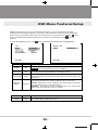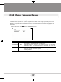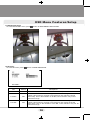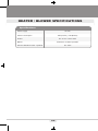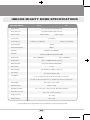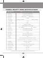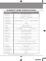
1
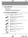
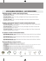
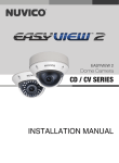
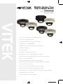
Mighty Series True
Day & Night Dome
Cameras
700 TVL Day & Night
Dome Cameras
VITEK
• 1/3” Sony High Density EXVIEW CCD
• 700 TVL High Resolution
• Sony Effio-E Digital Signal Processor
• 0.0003Lux (F1.2@50IRE)
• 2DNR - Two Dimensional Noise Reduction
• Motion Detection
• Privacy Mask
• Adaptive Tone Reproduction
• Secondary Video Output (Cable Included)
• OSD (On Screen Display) for Camera Function Setup
• Flush or Surface Mount
• Infinity Ball Mount for Any Viewing Angle
• UTP Interface and Heater / Blower Options Available
• ¾” Conduit Knockouts
• Indoor and Outdoor IP 686 Vandal Versions
• 35 IR LED’s with 90ft Range (Model L35)
• Optional Extreme Cold (-60°F) Temperature Kit Available
• Available in Ivory or Black
• Dual Voltage 12VDC & 24VAC
BLACK
TABLE OF CONTENTS
BOX CONTENTS
1
INCLUDED ACCESSORIES
1
AVAILABLE MODELS/ACCESSORIES
2
MIGHTY DOME LAYOUT
3
INSTALLATION
4
JUNCTION BOX INSTALLATION
5
OPEN GIMBAL COVER
6
CONNECTIONS
7
LENS ADJUSTMENT
8
INFINITE AXIS GIMBAL ADJUSTMENT
9
OSD MENU FEATURES/SETUP
1. In the menu
10
2. MAIN menu
10
3. MAIN menu - 1
10
4. MAIN menu - 2
11
5. SHUTTER/AGC menu
11
6. SHUTTER/AGC > AUTO SETUP menu
12
7. SHUTTER/AGC > MANUAL SETUP menu
13
8. LENS menu
13
9. DAY/NIGHT menu
13
10. PICT ADJUST menu
15
11. WHITE BAL menu
15
12. ATR (Adaptive Tone Reproduction) menu
17
13. BACKLIGHT menu
18
14. NR menu
18
15. MOTION DET menu
19
16. PRIVACY menu
19
10
TABLE OF CONTENTS
17. LANGUAGE menu
20
18. CAMERA ID menu
20
19. CAMERA RESET
21
20. EXIT
21
VITEK
DIMENSIONS
22
HEATER/BLOWER SPECIFICATIONS
23
INDOOR MIGHTY DOME SPECIFICATIONS
24
VANDAL MIGHTY DOME SPECIFICATIONS
25
IR MIGHTY DOME SPECIFICATIONS
WARRANTY
26
29
BOX CONTENTS
1) Dome Camera
2) Accessories
3) VT-MD-2VOC (Secondary Video Output Cable)
4) Instruction Manual & Mounting Template
INCLUDED ACCESSORIES
Torx Wrench - (Vandal & IR Versions Only)
Type #: T20
Length: 63mm / Diameter: 4mm
Qty: 1
Phillips head Screws - (Vandal & IR Versions Only)
For attaching the dome cover to the flush housing.
Type #: Phillips head M4x10
Length: 10mm / Diameter: 4mm
Qty: 4
Self Tapping Screws
For attaching the surface mount housing or the the flush mount base to a
solid surface.
Type #: Phillips St4x30
Length: 30mm / Diameter: 4mm
Qty:4
Self Tapping Screws - (Indoor Version Only)
For attaching the dome cover to the flush housing.
Type #: Phillips St4x12
Length: 12mm / Diameter: 4mm
Qty: 4
Dowels
If necessary, use the to help secure the self tapping screws.
Length: 30mm / Diameter: 7mm
Qty: 4
Secondary Video Output Cable for Mighty Domes:
VT-MD-2VOC
109.0
For viewing video image during installation.
Qty: 1
Mounting Template
Surface Mount
Mounting Template
Qty: 1
70.0
1
BLACK
AVAILABLE MODELS / ACCESSORIES
INDOOR MIGHTY DOME CONFIGURATIONS:
VTD-MP2810DN: Indoor True Day and Night Color Dome Camera with 2.8-10mm
Varifocal Lens & 700TVL
VTD-MP922DN: Indoor True Day and Night Color Dome Camera with 9-22mm
Varifocal Lens & 700TVL
VTD-MP1850DN: Indoor True Day and Night Color Dome Camera with 18-50mm
Varifocal Lens & 700TVL
VANDAL RESISTANT MIGHTY DOME CONFIGURATIONS:
VTD-MVP2810DN: Vandal Resistant True Day and Night Color Dome Camera with
2.8-10mm Varifocal Lens & 700TVL
VTD-MVP922DN: Vandal Resistant True Day and Night Color Dome Camera with
9-22mm Varifocal Lens & 700TVL
VTD-MVP1850DN: Vandal Resistant True Day and Night Color Dome Camera with
18-50mm Varifocal Lens & 700TVL
IR MIGHTY DOME CONFIGURATIONS:
VTD-MVP2810/L35: Vandal Resistant Color Dome Camera with 2.8-10mm Varifocal
Lens, 700TVL & 35 IR LED’s
VTD-MVP922/L35: Vandal Resistant Color Dome Camera with 9-22mm Varifocal
Lens, 700TVL & 35 IR LED’s
VTD-MVP1850/L35: Vandal Resistant Color Dome Camera with 18-50mm Varifocal
Lens, 700TVL & 35 IR LED’s
Optional Mounts & Accessories:
1. Heater/Blower Option 24VAC: (Vandal Resistant Models)
2. UTP Option: Unshielded Twisted Pair Transceiver Built-In
3. VT-MD/FMP: Flush Mount Plate for installation in drop ceilings or can be used as cover plate when using 4S
Junction Box
4. VT-MD/PLMT: Mighty Dome Pole Mount Adapter - Requires VT-MD/WMT Wall Mount
5. VT-MD/CMT: Mighty Dome Ceiling/Pedestal Mount (Can be extended if necessary)
6. VT-MD/CNMT: Mighty Dome Corner Mount Adapter - Requires VT-MD/WMT Wall Mount
7. VT-MD/WMT: Mighty Dome Wall Mount (Available In Ivory or Black)
8. VT-MD-EMP: Extender Mounting Plate - Use as stand-off for cable management and extended viewing angle
1.
2.
3.
4.
2
5.
6.
7.
8.
MIGHTY DOME LAYOUT
1) Lens
8) Dome Cover Ring
2) Power Input Connector(12VDC /
24VAC)
9) Flush Mount Base
3) Video Output Connector - BNC
4) Camera Holder and 2nd Video
output
5) Ball with the Camera Assembly
6) Safety Wire
7) Bubble
10) Surface Mount Plate
11) Assembly Screws - Torx M4x9
(Vandalproof)
12) Assembly Screws - Phillips
ST4x12 (Indoor) / Phillips M4x10
(Vandalproof / IR)
13) Mounting Screws - Phillips ST4x30
3
BLACK
INSTALLATION
1) Dome Cover
1.1 Vandal Proof Domes - Use the provided Torx wrench to unscrew the vandal
proof screws and remove the dome cover.
1.2 Indoor Domes - Turn the dome cover to the left to remove the dome cover.
2) Flush Mount Installation:
Using four St4x30 screws, attach the flush mount base to a sturdy surface.
Optional flush mount decorator plate. Model: VT-MD-FMP
3) Surface Mount Installation:
Drill pilot holes at the mounting location using the provided mounting template.
Using four St4x30 screws, mount the surface mount housing to a sturdy
surface. Using four ST4x12 (Indoor) screws or M4x10 (Vandal-proof) screws,
attach the flush mount base to the surface mount housing.
4
JUNCTION BOX INSTALLATION
Mighty Domes can easily be flush or surface mounted to an electrical junction
box (4S J-Box) using the pre-drilled mounting holes on either the surface mount
housing or the the flush mount base.
5
BLACK
OPEN GIMBAL COVER
To adjust the zoom and the focus, the gimbal needs to be removed temporarily
from its base.
1) Remove the ball gimbal from its socket, and hold the base firmly with one hand.
2) Gently squeeze Point A and B and pull away from the base until the gimbal is
removed from the base.
3) Replace the Gimbal cover by aligning the cover to the base and pressing down
until it snaps back onto the base.
6
CONNECTIONS
• Power connection: 12VDC or 24VAC dual input.
• All Mighty Dome cameras come standard with a secondary video output. The
secondary video cable (VT-MD-2VOC) is included in the box.
VTM-LCD
7
BLACK
LENS ADJUSTMENT
LENS ADJUSTMENT
1) Remove the Gimbal cover from the Gimbal base.
1.) Remove the Gimbal Cover from the Gimbal Base
8
2) Loosen Zoom & Focus screws and make necessary adjustments as shown.
2.) Field
Loosen
ZoomTelephoto(T)
& Focus screws
and make necessary adjustments as shown.
of view:
to Wide(W)
Field
of
View:
Telephoto
(T)
to
Wide
(W)
Focus: Near(N) to infinity( )
Focus: Near (N) to Infinity ( )
8
3)
3.)OSD
OSDJoystick
JoystickControl
Control
4)
4.)Reattach
Reattachthe
thegimbal
gimbalcover
coverto
tothe
thegimbal
gimbalbase.
base
3
OSD Joystick
Control
8 8
BLACK
BLACK
INFINITE AXIS GIMBAL ADJUSTMENT
Rotation and “Friction Hold” Placement
The Gimbal mechanism yields maximum rotation and placement as shown below.
9
OSD Menu Features/Setup
SETUP menu
1 In the menu
Use
Press
,
buttons to move the cursor and
,
buttons to change the settings.
button to select or enter.
button stands for MENU or ENTER button.
2 MAIN menu
Follow the chart for submenu settings
MAIN menu-1
MAIN menu-2
3 MAIN menu-1
MAIN menu-1
Default
SHUTTER
/AGC
AUTO
Sets the parameters related to the shutter mode and AGC for AUTO and
MANUAL settings. See page 11 for ‘SHUTTER/AGC menu' details.
Descriptions
LENS
AUTO
Selects the lens type, AUTO or MANUAL. AUTO supports DC auto-iris lens
only. See page 13 ‘LENS menu' for details.
DAY/NIGHT
AUTO
Sets DAY/NIGHT mode to AUTO, COLOR or B/W.
AUTO – Camera switches DAY from/to NIGHT automatically.
BURST, DELAY CNT, DAY NIGHT, NIGHT DAY can be set.
See page 13 for ‘DAY/NIGHT menu' details.
COLOR – Day/Night is disabled and forces to DAY mode only.
B/W – Day/Night is disabled and forces to NIGHT mode only.
Camera removes IR cut filter and switches to B/W.
PICT ADJUST
-
WHITE BAL
ATW
Sets ATW, PUSH, USER1, USER2, ANTI CR, MANUAL or PUSH LOCK.
See page 15 for ‘WHITE BAL menu' details.
ATR
OFF
Sets ON/OFF for enabling/disabling ATR (Adaptive Tone Reproduction)
compensation for the better dynamic range of the image.
See page 17 for ‘ATR menu' to adjust the dynamic ranges.
BACKLIGHT
OFF
Selects BACKLIGHT mode out of OFF, HLC or BLC. Areas and gains for
HLC and BLC are factory preset and not user adjustable.
Sets MIRROR, BRIGHTNESS, CONTRAST, SHARPNESS, HUE or GAIN.
See page 15 for ‘PICT ADJUST menu' details.
NEXT
Moves to MAIN menu-2.
EXIT
Exits the setup menu. To save the changes, move cursor to 'SAVE ALL'
and press
button before exiting the setup menu.
SAVE ALL
Saves all parameters by pressing
button.
10
BLACK
OSD Menu Features/Setup
4 MAIN menu-2
MAIN menu-2
Default
NR
-
MOTION DET
OFF
PRIVACY
OFF
LANGUAGE
ENGLISH
CAMERA ID
OFF
CAMERA
RESET
Descriptions
Sets the noise reduction parameters for NR MODE, Y LEVEL and
C LEVEL. See page 18 for ‘NR menu' details.
Sets ON/OFF for enabling/disabling MOTION DET.
See page 19, ‘MOTION DET menu' for the parameter settings.
Sets ON/OFF for enabling/disabling PRIVACY.
See page 19, 'PRIVACY menu' for the parameter settings.
Selects the language out of 7 languages.
Sets ON/OFF for enabling/disabling of ID display.
Factory default ID is this version of the camera.
User programmed camera ID will be lost and restored with Factory default
ID after CAMERA RESET. See page 20, 'ID menu' for editing ID.
Restores FACTORY DEFAULT.
To save the restored parameters, move cursor to 'SAVE ALL' and press
button before exiting the setup menu.
BACK
Returns to MAIN menu-1.
EXIT
Exits the setup menu.
To save the changes, move cursor to 'SAVE ALL' and press
SAVE ALL
Saves all settings by pressing
button.
button.
5 SHUTTER/AGC menu
This menu offers how to control/select SHUTTER, AUTO IRIS and AGC to get the best image for the
high luminance and the low luminance according to the scene.
For example, to reduce the wash out and extend the dynamic range for the highlight scene, it is
improved by SHUTTER+AUTO IRIS in the outdoor daylight. This mode may show color rolling or the
video level hunting problem in certain lighting condition such as fluorescent lights.
Flickerless mode reduces the flickers by NTSC camera under 50Hz light or PAL camera under
60Hz light. MAIN> SHUTTER/AGC> MANUAL> SHUTTER must be set to 1/100 (NTSC), 1/120 (PAL)
and MAIN> SHUTTER/AGC> AUTO> MODE to AUTO IRIS. Normal shutter speed with an auto iris
lens should be set to 1/60 (NTSC) and 1/50 (PAL) for the best sensitivity.
To enter SHUTTER/AGC menu, press
button at MAIN menu-1>SHUTTER/AGC.
11
OSD Menu Features/Setup
6 SHUTTER/AGC>AUTO SETUP menu
AUTO SETUP
Default
Descriptions
Selects the shutter mode from AUTO IRIS or SHUT+AUTO IRIS when
MAIN>LENS>AUTO but it is fixed to SHUT if MAIN>LENS>MANUAL.
AUTO IRIS - Light level is controlled by an auto iris lens only.
For proper auto iris operation, the auto iris operation mode in MAIN>
LENS>AUTO>MODE must be set to AUTO.
HIGH LUMINANCE
MODE
AUTO
IRIS
The shutter speed is fixed to the setting at MAIN>SHUTTER/AGC>
MANUAL> SHUTTER in this mode.
Set SHUTTER to 1/60 (NTSC) or 1/50 (PAL) for the best sensitivity
unless it is in Flickerless mode.
To set Flickerless mode: MAIN>SHUTTER/AGC>MANUAL>SHUTTER
must be set to 1/100 (NTSC), 1/120 (PAL) and MAIN>SHUTTER/AGC>
AUTO>MODE to AUTO IRIS.
SHUT+AUTO IRIS- Light level is controlled by the combination of an
auto iris lens and shutter control to improve the highlight from washout and extend the dynamic range. Shutter speed can vary between
1/60(1/50)~1/10,000sec.
This mode enhances the overall video quality of daylight but may show
a smeared image in bright spotlights. However, color rolling or video
level hunting may occur under a certain lighting condition such as
fluorescent lights.
LOW
LUMINANCE
BRIGHTNESS
032
Adjusts the brightness of the image by an auto iris lens or a shutter
speed control + an auto iris lens.
MODE
AGC
Sets AGC to compensate the video level when the scene is dim.
BRIGHTNESS
x0.50
Sets the brightness level which starts AGC from x0.25, x0.50, x0.75 and
x1.0 of full video level.
If set to x0.50, the camera will start AGC when the video level goes
down to below the 50% level.
NOTICE : The setting AUTO IRIS at SHUTTER/AGC>AUTO SETUP>HIGH LUMINANCE MODE will be
changed to SHUT+AUTO IRIS if MAIN menu-1>LENS is changed to MANUAL.
As a result, the lens iris can NOT be fully opened when MAIN menu-1>LENS>AUTO IRIS>
MODE is OPEN.
This can be recovered by setting SHUTTER/AGC>AUTO SETUP>HIGH LUMINANCE MODE
to AUTO IRIS.
12
BLACK
OSD Menu Features/Setup
7 SHUTTER/AGC>MANUAL SETUP menu
MANUAL
SETUP
Default
Descriptions
MODE
SHUT
+AGC
Compensates the video level by the manual shutter control and AGC.
SHUTTER
1/60
(1/50)
Sets the manual shutter to 1/60(1/50), 1/100(1/120), 1/250,1/500,1/1000,
1/2000,1/4000 or 1/10000.
Manual shutter is only useful when luminance is unchanged.
AGC
6.00
Sets AGC gain in dB. Higher gain compensates for a brighter scene, but
noise increases.
Manual AGC can be set to 6, 12, 18, 24, 30, 36, 42 or 44 8dB.
8 LENS menu
To enter LENS menu, press
AUTO IRIS
TYPE
button at MAIN menu-1>LENS>AUTO.
Default
DC
MODE
AUTO
SPEED
080
Descriptions
MUST BE SET TO DC ONLY.
This camera does NOT support video type auto iris lens.
AUTO – Lens iris is automatically controlled according to the scene’s
light level.
OPEN – Lens is fully opened regardless of the light level.
CLOSE – Lens is fully closed.
Adjusts the iris control speed.
The lower the value, the faster the speed.
If the speed is too slow or fast, the iris control may be unstable.
9 DAY/NIGHT menu
To enter DAY/NIGHT menu, press
button at MAIN menu-1>DAY/NIGHT
13
OSD Menu Features/Setup
IMPORTANT ACTIVITY!!!
DAY->NIGHT and NIGHT->DAY operations must be examined and verified at the final
installation.
Block the lens for a few seconds for NIGHT mode, then release and let it return to DAY mode.
If camera stays at NIGHT mode for more than 10sec, slightly increase ‘N→D THRES’ and repeat the forementioned steps.
If the scene is too dim or the lens iris was adjusted too low (near close), it may not return to DAY.
DAY/NIGHT
Default
Descriptions
BURST
OFF
BURST mode contains color burst signal when the camera switches to B/W.
ON mode maintains the same color signal in B/W so that the video signal
provides better compatibility with certain color equipment.
OFF mode removes the color burst signal B/W video and increase the total TV
lines.
DELAY
CNT
005
DELAY CNT is the time in seconds before Day↔Night switches. DELAY can
avoid the unwanted/frivolous switching of short term lights such as light from
a passing car.
DAY→NIGHT
005
DAY→NIGHT mode sets a threshold level to determine when switch from
DAY to NIGHT. Lower (Higher) value makes the camera switched from Day to
Night at lower (higher) illumination.
If the camera stays in Color at night time, increase DAY→NIGHT threshold
value until it just switches to Night.
CAUTION If the value between DAY→NIGHT and NIGHT→DAY is
minimal, then camera may switch between DAY and NIGHT mode
repeatedly.
NIGHT→
DAY.
3
NIGHT→DAY mode sets a threshold level to determine when to switch from
NIGHT to DAY. Lower (Higher) value makes the camera switched from Night
to Day at lower (higher) illumination.
If the camera stays in B/W mode during day time, decrease NIGHT→DAY
threshold value until it switches to Day.
CAUTION If the value between DAY→NIGHT and NIGHT→DAY is
minimal, then camera may switch between DAY and NIGHT mode
repeatedly.
14
BLACK
OSD Menu Features/Setup
10 PICT ADJUST menu
To enter PICT ADJUST menu, press
button at MAIN menu-1>PICT ADJUST.
PICT ADJUST
Default
MIRROR
OFF
Picture will be flipped horizontally if it turns ON.
Descriptions
BRIGHTNESS
000
Increases or decreases the brightness of the picture.
This is different from that of DC iris lens because it simply increases or
decreases the digital gain of the video.
Do not increase this too much or the dynamic range for the highlight area
will decrease.
CONTRAST
120
Increases or decreases the contrast of the picture.
SHARPNESS
128
Increases or decreases the sharpness of the picture.
Too much sharpness can make the image too harsh and show more noise
as well as line flicker at the edge of object in the picture.
HUE
128
Adjusts hue for NTSC version only.
GAIN
128
Increases or decreases the color gain of the picture.
11 WHITE BAL menu
White balance can be set to ATW, PUSH, USER1, USER2, ANTI CR, MANUAL or PUSH LOCK.
ATW (Auto Tracking White balance) and PUSH (Full pull-in) are continuously monitoring/analyzing the
color temperature of the incoming light and correcting the white balance.
ATW limits the color temperature range at about 2,500˚K~8,500˚K to reduce the excessive
compensation for the big object which has a single color.
PUSH has no limits between about 1,800˚K~10,500˚K but it may over-compensate the white balance for
the big object which has a single color.
In cases where it goes under 2,500˚K such as halogen light, ATW may stop. If so, PUSH mode is
recommended.
USER1 and USER2 are a fixed white balance which is user-programmable by R-GAIN and B-GAIN and
useful only for the steady light.
ANTI CR (Anti Color Rolling) can reduce color rolling under the fluorescent light when the camera
operates in shutter control without an auto iris lens. (NTSC version only)
15
OSD Menu Features/Setup
MANUAL white balance is a kind of fixed white balance which is user-programmable by B-GAIN.
(R-GAIN will be automatically adjusted in accordance with B-GAIN) and useful only for the steady light.
PUSH LOCK is a fixed white balance where the white balance is compensated only while the
button
is pressed at MAIN>WHITE BAL>PUSH LOCK and finishes the white balance when
button is
released.
To enter ATW (MANUAL) menu, press
ATW
button at MAIN menu-1>WHITE BAL>ATW(MANUAL).
Default
Descriptions
SPEED
250
Sets the AWB compensating speed. Lower value makes AWB faster.
CAUTION Too fast an AWB may force color oscillation.
DELAY CNT
001
Adjusts the AWB compensation period to next update of AWB.
The smaller value will update AWB more frequently (faster).
ATW FRAME
X2.00
Determines the ATW range with respect to the fundamental range.
A higher value than x1.00 extends the ATW range at lower and higher color
temperature.
Selects INDOOR or OUTDOOR.
Their ATW is optimized for the limited application and cannot cover.
ENVIRONMENT
INDOOR
INDOOR - Optimized for Indoor installation and compensates ATW for low
color temperature such as incandescent lights.
OUTDOOR - Optimized for outdoor sunlit applications and compensates
ATW for high color temperature such as daylight.
MANUAL WB
Default
Descriptions
LEVEL
064
Manual White Balance Adjustment value.
16
BLACK
OSD Menu Features/Setup
12 ATR (Adaptive Tone Reproduction) menu
The ATR feature improves the dynamic range and the visibility of the image by providing the optimal
gradation compensation of the image in one field. This is achieved by two ways of image processing,
luminance compression and contrast enhancement, so that the tone can be enhanced at highlighted and
dark areas.
To enter ATR menu, press
ATR
button at MAIN menu-1>ATR.
Default
Descriptions
LUMINANCE
MID
Compresses the highlighted area and enhances the dark area so that the
entire image can converge toward the medium level.
LOW will compensate minimally and HIGH will average out the image.
With setting HIGH, the image may look less contrastive and noise may
increase in the dark area.
CONTRAST
MID
Adjusts the strength of the image contrast.
If set to too high, the dark area may lose detail and the high luminance
area may saturate.
17
OSD Menu Features/Setup
13 BACKLIGHT menu
To enter BACKLIGHT menu, press
button at MAIN menu-1>BACKLIGHT.
BLC OFF
BLC ON
HLC OFF
HLC ON
14 NR menu
To enter NR menu, press
button at MAIN menu-2>NR.
NR
Default
NR MODE
Y/C
Selects OFF, Y, C or Y/C which noise reduction is performed with.
Descriptions
Y LEVEL
006
Indicates the noise reduction strength for the luminance signal.
Higher value performs stronger noise reduction and makes the image
less sharp. Due to the limitation of 2D NR, noise reduction may not be
effective enough.
C LEVEL
004
Indicates the noise reduction strength for the chrominance signal.
Higher value performs stronger noise reduction and makes the image
less sharp. Due to the limitation of 2D NR, noise reduction may not be
effective enough.
16
18
BLACK
OSD Menu Features/Setup
15 MOTION DET menu
Up to 4 motion detection areas are available and each area is programmable in size and location.
The motion is displayed by means of blocks when MAIN menu-2>MOTION DET and MOTION
DET>BLOCK DISP are ON.
To enter MOTION DET menu, press
button at MAIN menu-2>MOTION DET>ON.
MOTION DET
Default
Descriptions
DETECT SENSE
080
Adjusts the sensitivity for detecting motion. A higher value is more sensitive.
BLOCK DISP
ON
MONITOR
AREA
Enables or disables displaying blocks for the area where the motion is
detected.
OFF
Displays four motion windows as programmed in sizes and positions.
AREA SEL
1/4
Selects AREA1~AREA4 to be adjusted.
TOP (BOTTOM) button moves up and
button moves down the top
(bottom) border of the selected window at AREA SEL.
LEFT (RIGHT) button moves left and
button moves right the left
(right) border of the selected window at AREA SEL
16 PRIVACY menu
Up to 8 privacy areas are available and each area is programmable in size and location.
The number of privacy areas is limited to four when MOTION DET>MONITOR AREA is ON.
The privacy areas are masked with the color selected by PRIVACY>COLOR.
To enter PRIVACY menu, press
button at MAIN menu-2>PRIVACY>ON.
19
OSD Menu Features/Setup
PRIVACY
Default
Descriptions
Selects one of AREA1~AREA8 to be adjusted.
AREA SEL
TOP(BOTTOM) button moves up and
button moves down the top
(bottom) border of the selected window at AREA SEL.
1/8
LEFT(RIGHT) button moves left and
button moves right the left
(right) border of the selected window at AREA SEL
COLOR
1
Sets one of 8 colors for the selected mask window at AREA SEL.
TRANSP
1.00
Transparency rate for the mask can be adjusted.
0.00 - Mask is fully transparent and not visible.
0.50 - Mask is 50% transparent.
0.75 - Mask is 25% transparent.
1.00 - Mask is not transparent.
MOSAIC
OFF
Enables or disables the mosaic effect for the selected mask window at
AREA SEL
17 LANGUAGE menu
Seven languages, ENGLISH ,JAPANESE, DEUTCH, FRANCAIS, RUSSIAN, PORTUGUES and
ESPANOL, are available with this camera.
18 CAMERA ID menu
Up to 40 characters can be input for camera ID.
To enter CAMERA ID menu, press
button at MAIN menu-2>CAMERA ID.
CAMERA ID input line
COMMAND LINE
Use
,
,
,
selected character.
buttons to move a block cursor in character table and press
button to input the
To move the character input position on CAMERA ID input line, move a cursor to ←→ on COMMAND
LINE and press
button on ← or →.
To clear CAMERA ID input line, move a cursor to CLR on COMMAND LINE and press
button.
To set the location of CAM TITLE to be displayed on the monitor, move a cursor to POS and press
button. Then, the menu will disappear and the CAMERA ID will be displayed on the monitor.
Move CAMERA ID by using
,
Menu will appear again.
To finish CAM TITLE menu, press
,
,
buttons and press
button to fix.
button on RET on command line.
20
BLACK
OSD Menu Features/Setup
19 CAMERA RESET
Camera loads Factory defaults.
To save them, go to SAVE ALL and press
button.
20 EXIT
Exits SETUP MENU and returns to the normal display
21
DIMENSIONS
Vandal
31
Indoor
22
BLACK
HEATER / BLOWER SPECIFICATIONS
HEADER
Specifications
Power Supply
24 VAC
Power Consumption
10W (Heater) / .7W (Blower)
Heater
On: at 41ºF / Off at 59ºF
Blower
Continuous 24 Hour Operation
Extreme Weather Heater - Optional
On: -60ºF
23
INDOOR MIGHTY DOME SPECIFICATIONS
HEADER
Specifications
NTSC PAL
Image Device
1/3” Sony High Density EXVIEW CCD
Image Processor
Sony Effio-E Digital Signal Processor
Effective Pixels
976(H) x 494(V)
Scan System
976(H) x 582(V)
2:1 Interlace
Scan Frequency
59.94Hz(V), 15.734Khz(H)
50Hz(V), 15.625Khz(H)
Synchronization
Internal
Horizontal Resolution
700TVL
Sensitivity
0.0003Lux (F1.2@50IRE)*
S/N Ratio
More than 50dB with AGC OFF at 50IRE
Electronic Iris
White Balance
Motion Detection
1/60 ~ 1/100,000sec
1,800 ~ 10,5000K Automatic Tracking
YES (24x16 BLOCK ALARM AREA)
Privacy Mask
OSD Language
1/50 ~ 1/100,000sec
8 mask
EN, FR, DE, ES, POR, SC, RUS, JP
Day & Night
True Day and Night by ICR
Lens Options
F1.2 2.8-10mm DC Auto Iris IR Corrected ICR / F1.8 9-22mm
DC Auto Iris IR Corrected ICR / F1.5 18-50mm DC Auto Iris Corrected ICR
Video Output
VBS 1 Vpp +/- 10%, 75ohm
Operating Power
Operating Condition
Dimensions (H x Dia.)
24VAC / 12VDC
-4F ~ 122F (-20C ~ +50C), 85% RH. Max. Non-condensing
4.45” x 5.71” (113mm x 145mm)
Weight (Camera)
1lb / .46Kg
Weight (Carton)
1.6lb / .72Kg
*Light Sensitivity may vary depending on lens specifications and capsule density and color
24
BLACK
VANDAL MIGHTY DOME SPECIFICATIONS
HEADER
Specifications
NTSC
PAL
Image Device
1/3” Sony High Density EXVIEW CCD
Image Processor
Sony Effio-E Digital Signal Processor
Effective Pixels
976(H) x 494(V)
Scan System
976(H) x 582(V)
2:1 Interlace
Scan Frequency
59.94Hz(V), 15.734Khz(H)
50Hz(V), 15.625Khz(H)
Synchronization
Internal
Horizontal Resolution
700TVL
Sensitivity
0.0003Lux (F1.2@50IRE)*
S/N Ratio
More than 50dB with AGC OFF at 50IRE
Electronic Iris
1/60 ~ 1/100,000sec
1/50 ~ 1/100,000sec
White Balance
1,800 ~ 10,500K Automatic Tracking
Motion Detection
YES (24x16 BLOCK ALARM AREA)
Privacy Mask
8 mask
OSD Language
EN, FR, DE, ES, POR, SC, RUS, JP
Day & Night
Infrared Cut-Filter Removable Built-In
IP Rating
IP686
Lens Options
F1.2 2.8-10mm DC Auto Iris IR Corrected ICR / F1.8 9-22mm
DC Auto Iris IR Corrected ICR / F1.5 18-50mm DC Auto Iris Corrected ICR
Video Output
VBS 1 Vpp +/- 10%, 75ohm
Operating Power
Operating Condition
Dimensions (H x Dia.)
24VAC / 12VDC
-4F ~ 122F (-20C ~ +50C), 85% RH. Max. Non-condensing
4.45” x 6.73” (110mm x 170mm)
Weight (Camera)
2.3lb / 1043g
Weight (Carton)
2.9lb / 1315g
*Light Sensitivity may vary depending on lens specifications and capsule density and color
25
IR MIGHTY DOME SPECIFICATIONS
HEADER
Specifications
NTSC
PAL
Image Device
1/3” Sony High Density EXVIEW CCD
Image Processor
Sony Effio-E Digital Signal Processor
Effective Pixels
976(H) x 494(V)
Scan System
976(H) x 582(V)
2:1 Interlace
Scan Frequency
59.94Hz(V), 15.734Khz(H)
50Hz(V), 15.625Khz(H)
Synchronization
Internal
Horizontal Resolution
700TVL
Sensitivity
0.0003Lux (F1.2@50IRE)*
S/N Ratio
More than 50dB with AGC OFF at 50IRE
Electronic Iris
White Balance
IR LED’s
1/60 ~ 1/100,000sec
1/50 ~ 1/100,000sec
1,800 ~ 10,500K Automatic Tracking
35 IR LED’s with up to 90’ Range
Motion Detection
YES (24x16 BLOCK ALARM AREA)
Privacy Mask
8 mask
OSD Language
EN, FR, DE, ES, POR, SC, RUS, JP
Day & Night
Infrared Cut-Filter Removable Built-In
IP Rating
IP686
Lens Options
F1.2 2.8-10mm DC Auto Iris IR Corrected ICR / F1.8 9-22mm
DC Auto Iris IR Corrected ICR / F1.5 18-50mm DC Auto Iris Corrected ICR
Video Output
VBS 1 Vpp +/- 10%, 75ohm
Operating Power
Operating Condition
Dimensions (H x Dia.)
24VAC / 12VDC
-4F ~ 122F (-20C ~ +50C), 85% RH. Max. Non-condensing
4.45” x 6.73” (110mm x 170mm)
Weight (Camera)
2.3lb / 1043g
Weight (Carton)
2.9lb / 1315g
*Light Sensitivity may vary depending on lens specifications and capsule density and color
26
BLACK
VTM-LCDP Series
15”, 17“, and 19” Professional LCD Monitors
• 15”, 17“, and 19” Professional LCD Display Panels
• Designed for continuous 24/7 operation
• VGA, Looping BNC Composite, and S-Video Video
Inputs. DVI & HDMI Inputs on 17“ & 19” Versions
• Resolution up to 1280 X 1024 (17” & 19”)
• Stereo Audio Input/Output
• VESA Standard Mounting
27
CHRONO Series
8, and 16 Channel Digital Video
Recorders
• Highly efficient H.264 compression
H.264
• Built-in Data Redundancy
• Real-time recording and real-time playback
• System Setup Wizard and User Friendly GUI
• Multi-Resolution recording
• 4 Spot Output (8 &16 Channel)
• Highly efficient and stable proprietary Database
Structure
• Identical GUI for DVR and client viewer
• Built-in Point-of-Sales support
• Web clients & CMS (Central Management Software)
Included
• iPhone App
28
BLACK
LIMITED LIABILITY WARRANTY
VITEK products carry a three (3) year limited warranty. VITEK warrants
to the purchaser that products manufactured by VITEK are free of any
rightful claim of infringement or the like, and when used in the manner
intended, will be free of defects in materials and workmanship for a
period of three (3) years, or as otherwise stated above, from the date of
purchase by the end user. This warranty is non-transferable and extends
only to the original buyer or end user customer of a VITEK Authorized
Reseller.
The product must have been used only for its intended purpose, and
not been subjected to damage by misuse, willful or accidental damage,
caused by excessive voltage or lightning.
The product must not have been tampered with in any way or the guarantee will be considered null and void.
This guarantee does not affect your statutory rights.
Contact your local VITEK Reseller should servicing become necessary.
VITEK makes no warranty or guarantee whatsoever with respect to
products sold or purchased through unauthorized sales channels. Warranty support is available only if product is purchased through a VITEK
Authorized Reseller.
28492 CONSTELLATION ROAD VALENCIA, CA 91355
WWW.VITEKCCTV.COM