1
Kramer Electronics, Ltd.
USER MANUAL
Models:
VP-128H, Matrix Switcher
RC-1616, Remote Control
Contents
Contents
1
2
3
3.1
3.2
3.3
4
4.1
4.2
4.3
5
5.1
5.2
5.3
6
6.1
6.2
Introduction
Getting Started
Overview
About the VP-128H
About the RC-1616
Achieving the Best Performance
Your VP-128H Matrix Switcher
The VP-128H with the Front Panel and the Rear Panel Intact
The VP-128H Without the Front Panel (but with the Rear Panel)
The VP-128H Local Control Panel (Detached Front Panel)
Connecting a VP-128H Matrix Switcher
Connecting the VP-128H Matrix Switcher
Controlling via RS-232 (for example, using a PC)
Connecting the VP-128H (also RC-1616) via the 10 Base T network port
Your RC-1616 Remote Control
The RC-1616 with the Front Panel and the Rear Panel Intact
The RC-1616 Front Panel Detached
1
1
2
2
3
3
3
3
5
6
7
7
8
9
11
11
12
6.2.1
Setting the Dipswitches
13
7
8
8.1
Connecting a RC-1616 Remote Control
Operating the VP-128H Matrix Switcher
Switching OUT-IN Combinations
14
15
15
8.1.1
Operating in the AT ONCE Mode
15
9
10
10.1
Technical Specifications
Communication Protocols
Kramer 2000 Protocol Supported Subset
16
17
17
10.1.1 Use of Kramer Machines
10.1.2 Command Details
19
19
10.2
28
Sierra Video Systems (SVS) RS-232 Compatible Protocol
10.2.1 Command Details I
10.2.2 Command Details II
28
29
10.3
39
Generic Protocol Supported Subset
10.3.1 Use of Generic Machines
10.3.2 Command Details
39
39
i
Contents
Figures
Figure 1: VP-128H Matrix Switcher
Figure 2: VP-128H Local Control Panel
Figure 3: VP-128H Front View with Front Panel Detached
Figure 4: Connecting a PC without using a Null-modem Adapter
Figure 5: RJ-45 PINOUT
Figure 6: Connecting a VP-128H Matrix Switcher
Figure 7: RC-1616 Remote Control
Figure 8: RC-1616 Remote Control with its Front Panel Detached
Figure 9: Connecting up to 512 RC-1616 Remote Control Units to a VP-128H
4
6
6
8
9
10
11
12
14
Tables
Table 1: VP-128H Matrix Switcher Front Panel Features
Table 2: VP-128H Matrix Switcher Rear Panel Features
Table 3: VP-128H Front View with Front Panel Detached Features
Table 4: Crossover Cable RJ-45 PINOUT
Table 5: Straight-through Cable RJ-45 PINOUT
Table 6: RC-1616 Remote Control Front Panel Features
Table 7: RC-1616 Remote Control Rear Panel Features
Table 8: RC-1616 Front View with Front Panel Detached Features
Table 9: Dipswitch Definitions S2-1 to S2-8
Table 10: Dipswitch Settings (Levels controlled by the Panel)
Table 11: Technical Specifications of the VP-128H
Table 12: RS-232 Commands for Selecting Different Protocols
ii
5
5
6
9
9
11
12
12
13
13
16
17
KRAMER: SIMPLE CREATIVE TECHNOLOGY
Introduction
1
Introduction
Welcome to Kramer Electronics (since 1981): a world of unique, creative and
affordable solutions to the infinite range of problems that confront the video,
audio and presentation professional on a daily basis. In recent years, we have
redesigned and upgraded most of our line, making the best even better! Our
500-plus different models now appear in 8 Groups1, which are clearly defined
by function. Congratulations on purchasing your Kramer VP-128H Matrix
Switcher and/or RC-1616 Remote Control. The VP-128H Matrix Switcher is
ideal for the following typical applications:
Switching between up to 12 VGA computer inputs and up to eight VGA
display outputs, in which the use of native HD15 connectors for the inputs and
outputs eliminates the need for awkward HD15-to-BNC breakout cables. The
entire VP-128H is only 1RU high compared to 3RU that would be required if
the unit were built with BNC connectors on its rear panel
Any professional system requiring outstanding value in a 12x8 matrix
The RC-1616 Remote Control is ideal for sophisticated control from various
locations via the 10 Base T network. You can connect up to 512 RC-1616
Remote Control panels to one router: 256 XY panels and 256 single bus panels.
The package includes the following items:
VP-128H Matrix Switcher with a power cord and a Null-modem adapter;
or RC-1616 Remote Control with a power adapter
Windows®-based Kramer control software and this user manual2
2
Getting Started
We recommend that you:
Unpack the equipment carefully and save the original box and packaging
materials for possible future shipment
Review the contents of this user manual
Use Kramer high performance high resolution cables3
1 GROUP 1: Distribution Amplifiers; GROUP 2: Video and Audio Switchers, Matrix Switchers and Controllers; GROUP 3:
Video, Audio, VGA/XGA Processors; GROUP 4: Interfaces and Sync Processors; GROUP 5: Twisted Pair Interfaces;
GROUP 6: Accessories and Rack Adapters; GROUP 7: Scan Converters and Scalers; and GROUP 8: Cables and Connectors
2 Download up-to-date Kramer user manuals from the Internet at this URL: http://www.kramerelectronics.com
3 The complete list of Kramer cables is on our Web site at http://www.kramerelectronics.com
1
Overview
3
Overview
This section summarizes the:
VP-128H Matrix Switcher, see section 3.1
RC-1616 Remote Control, see section 3.2
3.1 About the VP-128H
The VP-128H is a true 12x8 matrix switcher for VGA / XGA signals that lets
you simultaneously route any or all of the 12 inputs to any or all of the 8
outputs. The high performance VP-128H is rugged, easy to service1, and fits
into one vertical space (1U) of a standard 19" rack. In particular, the
VP-128H includes:
A very reliable modular design2 (without any internal adjustments3), with
a detachable4 front panel that is fastened into the frame with two front panel
hand operated slide action latches. The detached front panel can be used as a
local control panel, by attaching it to the main electronics module within the
VP-128H using a 9-wire ribbon flat cable
12 input and eight output selector buttons
Video bandwidth of 315MHz that ensures transparent VGA / XGA
performance
DC coupled inputs and outputs
Storing and recalling setup options
The ability to store 10 setups in the control system in Flash
A RGB delayed switching mode (with a user selectable delay increment
of 500ms for each output ranging from 0 to 3.5 seconds) for any output
through black for clean transitions when switching between non genlocked
sources
A linear circuit path for the H and V channels, to cope with any
non-standard H and V sync levels
1 You can easily remove the front panel to access all the components from the front, without having to remove it from its rack
2 That has many advantages over competing systems that are not modular (for example, the Mean Time To Repair (MTTR)
using replacement modules would only take a few seconds, as opposed to hours for a non-modular design). All modules are
secured with positive latches (slide latches or positive leverage long-handle ejector/inserter devices with built-in latching
clasps). All plug-in modules are supported on all four sides. The rear panel is recessed 0.7 inches to protect the rear panel
connectors from damage
3 Video gain is set by 0.1% resistors
4 Removing the front panel reveals the two major slide in components—the main switching module and the plug-in power
supply unit—secured by latches to prevent accidental disconnection in mobile installations
2
KRAMER: SIMPLE CREATIVE TECHNOLOGY
Your VP-128H Matrix Switcher
A passive two BNC sync loop - useful to ensure deterministic switching1
Two VP-128H units can be cascaded
Control the VP-128H via the front panel buttons, or remotely:
Via the 10 Base T network of RC-1616 panels2 or RS-232 serial
commands transmitted by a touch screen system, PC, or other serial controller
3.2 About the RC-1616
The RC-1616 Remote Control is ideal for sophisticated control from various
locations via the 10 Base T network. You can connect up to 512 RC-1616
Remote Control panels to one router: 256 XY panels and 256 single bus panels.
3.3 Achieving the Best Performance
To achieve the best performance:
Connect only good quality connection cables, thus avoiding interference,
deterioration in signal quality due to poor matching, and elevated noise levels
(often associated with low quality cables)
Avoid interference from neighboring electrical appliances and position
the VP-128H / RC-1616 away from moisture, excessive sunlight and dust
4
Your VP-128H Matrix Switcher
The VP-128H Matrix Switcher can be used:
With the front panel and rear panel intact, see section 4.1
Without the front panel (the front panel is blocked off), but with the rear
panel intact, see section 4.2
With the VP-128H front panel detached, which functions as a local
control panel, see section 4.3
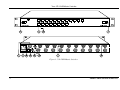
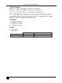
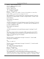
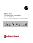
4.1 The VP-128H with the Front Panel and the Rear Panel Intact
Figure 1 and Table 1 and Table 2 define the front3 and rear panels of the
VP-128H Matrix Switcher:
1 Connect video with sync to either BNC. If desired, use the second BNC to loop the signal to another device
2 Network control will allow more powerful panels to store in the panel setup and recall schemes that are tailored to the
configuration of the panels controls. An entire router configuration can be sent to the router from the panel in under one
millisecond
3 The same switch assemblies and metalwork that make up the front panel are used on the remote control panel. You can
connect up to 512 remote control panels to one router: 256 XY panels and 256 single bus panels
3
Your VP-128H Matrix Switcher
Figure 1: VP-128H Matrix Switcher
4
KRAMER: SIMPLE CREATIVE TECHNOLOGY
Your VP-128H Matrix Switcher
Table 1: VP-128H Matrix Switcher Front Panel Features
#
1
2
3
Feature
Slide Action Latches
1
OUT Selector Buttons
3
IN Selector Buttons
Function
Fasten the front panel into the frame
2
Select the output to which the input is switched (from 1 to 8)
Select the input to switch to the output (from 1 to 12)
Table 2: VP-128H Matrix Switcher Rear Panel Features
#
1
2
3
4
5
6
7
8
Feature
RS-232 DB 9F Connector
Slow Blow Fuse
4
Power Connector
10 Base T Port
REF SYNC BNC Connector
REF SYNC BNC Connector
VGA/XGA Video INPUTS
VGA/XGA Video OUTPUTS
Function
Connects to the PC or other Serial Controller
20x5mm 0.5A slow blow fuse
AC connector enabling power supply to the unit
Connects to the 10 Base T network
5
When connected unit switches in vertical interval
When connected unit switches in vertical interval5
Connects to the VGA/XGA video inputs (1 to 12)
Connects to the VGA/XGA video outputs (1 to 8)
4.2 The VP-128H Without the Front Panel (but with the Rear Panel)
You can configure and operate the VP-128H without a front panel when
operating the VP-128H via a remote panel, RS-232 control, or 10 Base T
control.
1 These buttons operate in the ‘one out of n’ mode. When one of these buttons is pressed the previous button is cleared and
the new selection is latched and tallied. If the selected output is ‘locked’ the lamp in the output button flashes and the correct
input status is tallied via the input select buttons
2 Each output can be muted independently; and can be set to a delayed switch through black, with a user selectable delay
increment for each output
3 These buttons operate in the ‘one out of n’ mode. When one of these buttons is pressed the previous button is cleared and
the new selection is latched and tallied. When an output is selected the current state of the corresponding input is tallied in the
appropriate button. If the source is a breakaway, a flashing lamp indicates the audio selection. If the output being controlled is
locked, pressing the input select button has no affect
4 If the power supply needs to be replaced, you can access it from the front after removing the front panel (see section 4.3).
There is no harm leaving the power turned ON continuously, or in using the AC cord as the ON/OFF switch
5 With an HD15-to-BNC breakout, these two SYNC BNC connectors can be connected in a looping manner to a VP-128H
input or output. Inside the VP-128H, the BNC connectors connect to a sync separator circuit, which separates vertical sync
from composite video, composite sync, positive V pulse or negative V pulse. If left unconnected, the VP-128H operation is
not adversely affected. If two or more of the VP-128H inputs are already synchronized to each other, connect the BNC
connectors. By using the same reference to the cameras and to the VP-128H, a much cleaner switch will occur because it will
happen in the vertical interval
5
Your VP-128H Matrix Switcher
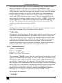
4.3 The VP-128H Local Control Panel (Detached Front Panel)
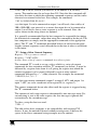
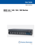
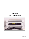
Figure 2 illustrates the front view of the VP-128H local control panel1:
Figure 2: VP-128H Local Control Panel1
The local control panel1 connects via a flat cable to the main switching
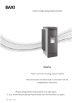
module inside the VP-128H. Figure 3 and Table 3 define the front view of the
VP-128H after its local control panel1 is detached:
Figure 3: VP-128H Front View with Front Panel Detached
Table 3: VP-128H Front View with Front Panel Detached Features
#
Feature
1 Release Latches
2 9-wire Ribbon Flat Cable with
DB9M connectors
3 Main Switching Module
4 Plug-in Power Supply Unit
4a Power Switch
4b Slide Action Latch
Function
Fasten the main switching module into the frame
Connects the circuitry on the (detached) front panel to the main
electronics module
Provides easy accessibility for service and repair
Detachable power module with a power switch and slide action latch on
the front side, and 6-pins on the rear side that transmit power to the power
connector (see item 3 in Table 2)
Illuminated switch for turning the unit ON or OFF
Fastens the plug-in power supply unit into the frame
1 The front panel when it is detached
6
KRAMER: SIMPLE CREATIVE TECHNOLOGY
Connecting a VP-128H Matrix Switcher
5
Connecting a VP-128H Matrix Switcher
You can control the VP-128H via:
Its front (local) panel, see section 5.1
RS-232. For example, by connecting a PC via the null-modem adapter
(when using the Kramer Control software or other controller) if control via
RS-232 is required (see section 5.2)
10 Base T network (see section 5.3)
The RC-1616 Remote Control (see section 6)
5.1 Connecting the VP-128H Matrix Switcher
This section describes how to connect the VP-128H.
To connect your VP-128H Matrix Switcher1, connect the following2:
1. Connect up to 12 VGA/UXGA sources to the 12 HD15F input
connectors. For example1, connect a computer graphics source to the
INPUT 1 HD15F connector, and a laptop graphics source to the INPUT
12 HD15F connector.
2. Connect up to 8 HD15F output connectors to up to3 8 VGA/UXGA
acceptors. For example1, connect the OUTPUT 1 HD15F connector to the
VGA/UXGA acceptor 1, for example, a projector, and connect the
OUTPUT 8 HD15F connector to the VGA/UXGA acceptor 8, for
example, a display.
3. Connect the Sync reference BNC connectors (optional).
4. Connect a PC (if required) to the RS-232 port, see section 5.2.
5. Connect the 10 Base T network port (if required), see section 5.3.
6. Connect the power cord4.
1 As the example in Figure 6 illustrates
2 Switch OFF the power on each device before connecting it to your VP-128H. After connecting your VP-128H, switch on its
power and then switch on the power on each device
3 When less than 8 outputs are required, connect only those outputs of the VP-128H and leave the other outputs unconnected
4 We recommend that you use only the power cord that is supplied with this machine
7
Connecting a VP-128H Matrix Switcher
5.2 Controlling via RS-232 (for example, using a PC)
You can connect a PC to the RS-232 port of the VP-128H unit, with or1
without using a Null-modem adapter (provided with the machine):
To connect a PC to the VP-128H unit, using the Null-modem adapter
provided with the machine:
Connect the RS-232 DB9 rear panel port on the VP-128H unit to the
Null-modem adapter and connect the Null-modem adapter with a 9 wire flat
cable to the RS-232 DB9 port on your PC
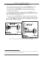
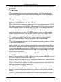
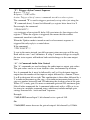
To connect a PC to the VP-128H unit without using a Null-modem adapter:
Connect the RS-232 DB9 port on your PC to the RS-232 DB9 rear panel
port on the VP-128H unit, as Figure 4 illustrates (depending on whether the
PC has a 9-pin or 25-pin connector)
Figure 4: Connecting a PC without using a Null-modem Adapter
1 The construction of the RS-232 I/O includes internal jumpers that allow the VP-128H to require an external null modem or
use a generic pin-to-pin 9 pin cable to a PC with no Null-modem adapter
8
KRAMER: SIMPLE CREATIVE TECHNOLOGY
Connecting a VP-128H Matrix Switcher
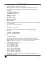
5.3 Connecting the VP-128H (also RC-1616) via the 10 Base T network
port
To connect the VP-128H (also the RC-1616) via the 10 Base T port, do the
following:
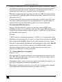
Connect the VP-128H 10 Base T port to the VP-128H 10 Base T port to
the RC-1616 10 Base T port, when not using a hub, via a crossover cable with
RJ-45 connectors, as Table 4 and Figure 5 define
Figure 5: RJ-45 PINOUT
Table 4: Crossover Cable RJ-45 PINOUT
EIA /TIA 568A
Side 2
PIN
1
2
3
4
5
6
7
8
EIA /TIA 568B
Side 1
Wire Color
Green / White
Green
Orange / White
Blue
Blue / White
Orange
Brown / White
Brown
PIN
1
2
3
4
5
6
7
8
Wire Color
Orange / White
Orange
Green / White
Blue
Blue / White
Green
Brown / White
Brown
Pair 1
4 and 5
Pair 1
Pair 2
3 and 6
Pair 2
4 and 5
1 and 2
Pair 3
1 and 2
Pair 3
3 and 6
Pair 4
7 and 8
Pair 4
7 and 8
If connecting the VP-128H / RC-1616 10 Base T port to the 10 Base T
network port on a network hub (for example, to connect multiple RC-1616
panels to one VP-128H) use a straight-through cable with RJ-45 connectors,
as Table 5 defines
Table 5: Straight-through Cable RJ-45 PINOUT
EIA /TIA 568A
Side 2
PIN
1
2
3
4
5
6
7
8
Wire Color
Orange / White
Orange
Green / White
Blue
Blue / White
Green
Brown / White
Brown
EIA /TIA 568B
Side 1
PIN
1
2
3
4
5
6
7
8
Wire Color
Orange / White
Orange
Green / White
Blue
Blue / White
Green
Brown / White
Brown
9
Connecting a VP-128H Matrix Switcher
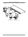
Figure 6 illustrates how to connect the VP-128H (without a remote control
panel):
Figure 6: Connecting a VP-128H Matrix Switcher
10
KRAMER: SIMPLE CREATIVE TECHNOLOGY
Your RC-1616 Remote Control
6
Your RC-1616 Remote Control
The RC-1616 Remote Control1 can be used:
With the front panel and rear panel intact, see section 6.1
With the RC-1616 front panel detached, see section 6.2
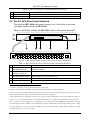
6.1 The RC-1616 with the Front Panel and the Rear Panel Intact
Figure 7, Table 6 and Table 7 define the front and rear panels of the RC-1616:
Figure 7: RC-1616 Remote Control
Table 6: RC-1616 Remote Control Front Panel Features
#
1
2
3
4
5
6
7
Feature
Slide Action Latches
VIDEO2 Button
AUDIO2 Button
VOLUME Up3 Button
VOLUME Down3 Button
IN Buttons
OUT Buttons
Function
Fasten the front panel into the frame
Affects video (audio does not switch)
Affects audio (video does not switch)
Pressing together with an IN / OUT Selector button decreases the level
Pressing together with an IN / OUT Selector button increases the level
Select the VGA/XGA input to switch to the VGA/XGA output (from 1 to 16)
Select the VGA/XGA output4 to which the VGA/XGA input is switched
(from 1 to 16)
1 It is fully enclosed on all sides, 2 inches deep, and includes a small processor board that performs the button functions and
provides the 10 Base T network interface
2 When the panel is powered ON, this button is OFF. Pressing this button will cause that button to latch ON. Pressing the
same button again will turn off this button. If either button is in the ON mode, pressing the other button will turn OFF the first
button (both buttons on, is an invalid condition). If both buttons are pressed at the same time, both buttons turn OFF (“AFV”)
and then re-selecting the desired button is required to turn ON that mode. When the video and audio sources are different, the
audio input lamp flashes on and off to indicate “breakaway”
3 The VOL UP button takes precedence over the VOL DOWN button if both are pressed. The VOL UP and VOL DOWN
buttons illuminate when pressed, but do not cause the Input Selector or Output Selector buttons to illuminate
4 Each output can be muted independently; and can be set to a delayed switch through black, with a user selectable delay
increment for each output
11
Your RC-1616 Remote Control
Table 7: RC-1616 Remote Control Rear Panel Features
#
Feature
1 9V DC 1A Connector
2 10 Base T Port
Function
+9V DC connector for powering the unit1
Connects to the 10 Base T network (used for remote panels)
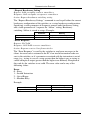
6.2 The RC-1616 Front Panel Detached
The detached RC-1616 front panel connects via a flat cable to the main
switching module inside the RC-1616.
Figure 8 and Table 8 define the RC-1616 with its front panel detached2:
Figure 8: RC-1616 Remote Control with its Front Panel Detached
Table 8: RC-1616 Front View with Front Panel Detached Features
#
Feature
1 9-wire Ribbon Flat Cable
with DB9M connectors
2 Dipswitches (first set 1 to 8 is
named: S1-1 to S1-8)3
3 Dipswitches (second set 1 to
8 is named: S2-1 to S2-8)3
4 Main Switching Module
5 Power Wires
Function
Connects the circuitry on the (detached) front panel to the main
electronics module
Set the panel’s network address4 (by default, set to OFF)
Determine the single bus or the “XY” operation, as well as the video and
audio control levels (see section 6.2.1)
Provides easy accessibility for service and repair
The red wire connects to the “+9V” and the black wire connects to the “GND”
1 Connect to an external ‘desk-top’ universal AC input power supply
2 Slide-in units held in place by latches to prevent accidental disconnection in mobile installations
3 You can access the dipswitches without removing the unit from its rack, as they are located inside the panel. You can access
them by unfastening the front panel via the slide action latches (item 1 in Figure 7)
4 These dipswitches have a dual purpose. There are two groups of 256 network addresses (512 in total). When the panel type
is ‘XY’ S1 to S8, select network addresses 1 to 256. When the panel type is ‘Single bus’ (determined by the setting of S2-1 –
refer to section 6.2.1), S1 through S5 serve a dual purpose. S1 through S5 select the OUTPUT bus controlled by that panel
and S1 through S5 select the 5 LSBs of network address 257 through 512. When the scan determines that the panel is a single
bus type panel, S1-6, S1-7 and S1-8 are the three MSB’s of the panel’s network address. This scheme puts a limit of 8 single
bus panels that can be set to the same output
12
KRAMER: SIMPLE CREATIVE TECHNOLOGY
Your RC-1616 Remote Control
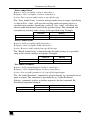
6.2.1
Setting the Dipswitches
You need to set the dipswitches when using more than one RC-1616 remote
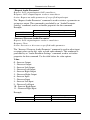
panel. Configure the RC-1616 unit by setting the dipswitches, as Table 9 and
Table 10 define:
Table 9: Dipswitch Definitions S2-1 to S2-8
DIP
Set as follows:
S2-1
ON for Single bus operation, OFF for “XY” operation
S2-2, S2-3, and S2-4
OFF (not in use)
S2-5, S2-6, S2-7, and S2-8
Select the levels controlled by the panel (see Table 10)
Table 10: Dipswitch Settings (Levels controlled by the Panel)
S2-5
S2-6
S2-7
S2-8
Levels controlled by the Panel
OFF
OFF
OFF
OFF
Not a valid situation
ON
OFF
OFF
OFF
This panel only controls Level 1
1
1
OFF
ON
OFF
OFF
This panel only controls Level 2
OFF
OFF
ON
OFF
This panel only controls Level 31
OFF
ON
OFF
ON
OFF
OFF
ON
OFF
This panel only controls Level 41
‘Video’ controls Level 1. ‘Audio’ controls Level 2
OFF
ON
ON
OFF
‘Video’ controls Level 2. ‘Audio’ controls Level 3
OFF
OFF
ON
ON
‘Video’ controls Level 3. ‘Audio’ controls Level 4
ON
OFF
ON
OFF
‘Video’ controls Level 1. ‘Audio’ controls Level 3
ON
OFF
OFF
ON
‘Video’ controls Level 1. ‘Audio’ controls Level 4
OFF
ON
OFF
ON
‘Video’ controls Level 2. ‘Audio’ controls Level 4
ON
ON
ON
OFF
‘Video’ controls Level 1 and 2. ‘Audio’ controls Level 3
ON
ON
OFF
ON
‘Video’ controls Level 1 and 2. ‘Audio’ controls Level 4
OFF
ON
ON
ON
‘Video’ controls Level 2. ‘Audio’ controls Level 3 and 4
ON
OFF
ON
ON
‘Video’ controls Level 1. ‘Audio’ controls Level 3 and 4
ON
ON
ON
ON
‘Video’ controls Level 1 and 2. ‘Audio’ controls Level 3 and 4
1 Any ‘Audio’, ‘Video Only’, ‘Audio Only’, ‘AFV’ or separate ‘Audio IN’ buttons in this situation do not function. When a
user wants to designate one of the above levels as audio, the legend in the switch (switches) may be changed accordingly
13
Connecting a RC-1616 Remote Control
7
Connecting a RC-1616 Remote Control
To connect a single RC-1616 Remote Control, do the following:
1. Connect the RC-1616 10 Base T port to the 10 Base T network, see section 5.3.
2. Detach the RC-1616 front panel by unfastening the slide action latches
(see item 1 in Figure 7) and set the dipswitches (see section 6.2.1).
3. Connect the 9V DC 1A power adapter (wall transformer) to the 9 V DC
socket and connect the transformer to the mains electricity.
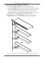
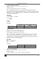
You can connect up to 512 RC-1616 Remote Control units to a single
VP-128H Matrix Switcher via the 10 Base T network (see Figure 9):
Figure 9: Connecting up to 512 RC-1616 Remote Control Units to a VP-128H
14
KRAMER: SIMPLE CREATIVE TECHNOLOGY
Operating the VP-128H Matrix Switcher
8
Operating the VP-128H Matrix Switcher
Operate your VP-128H via:
The front panel buttons
Remotely, from any one of up to 512 RC-1616 remote control panels via
10 Base T network and/or RS-232 serial commands transmitted by a touch
screen system, PC, or other serial controller
8.1 Switching OUT-IN Combinations
To switch an input to an output, do the following:
1. Press an OUTPUT SELECTOR1 button2.
The button lights.
2. Press an INPUT SELECTOR3 button2.
The button lights.
8.1.1
Operating in the AT ONCE Mode
The VP-128H only operates in the AT ONCE mode (that is, there is no
CONFIRM mode option) and pressing an OUT-IN combination implements
the switch immediately.
1 If the selected output is ‘locked’ the lamp in the output button flashes and the correct input status is tallied via the input
select button
2 This button operates in the ‘one out of n’ mode. When a button is pressed the previous button is cleared and the new
selection is latched and tallied
3 When an output is selected the current state of the corresponding input is tallied in the appropriate button. If the source is a
breakaway, a flashing lamp indicates the audio selection. If the output being controlled is locked, pressing the input select
button has no affect
15
Technical Specifications
9
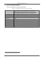
Technical Specifications
Table 11 includes the technical specifications:
1
Table 11: Technical Specifications of the VP-128H
INPUTS:
12 analog red, green, blue signals - 0.7 Vpp / 75 ; H & V syncs, TTL level on
HD15F connectors. The H and V channels are not TTL, they are linear
OUTPUTS:
8 analog red, green, blue signals - 0.7 Vpp / 75 ; H & V syncs, TTL level on
HD15F connectors. The H and V channels are not TTL, they are linear
+/- 1.5V (RGB channels only)
315MHz, Fully Loaded
< 0.06 %
< 0.17 deg.
<0.05%
60dB weighted to 5MHz
> 45dB@150MHz
20 front panel switches, RS-232, and RC-1616 control panels network
DC
90-240VAC 47-63Hz, 120mA AC
48.3cm x 30.5cm x 4.5cm (19-inch x 12-inch x 1U, W, D, H) rack mountable
5.5 kg. (12.2 lbs.) approx.
Power cord, Null modem adapter, Control software
MAX. OUTPUT LEVEL:
BANDWIDTH (-3dB):
DIFF. GAIN:
DIFF. PHASE:
K-FACTOR:
S/N RATIO:
CROSSTALK (all hostile):
CONTROLS:
COUPLING:
POWER SOURCE:
DIMENSIONS:
WEIGHT:
ACCESSORIES:
1 Specifications are subject to change without notice
16
KRAMER: SIMPLE CREATIVE TECHNOLOGY
Communication Protocols
10 Communication Protocols
The VP-128H is compatible with the Kramer 2000 Protocol Supported
Subset (see section 10.1), the Sierra Video Systems (SVS) RS-232
Compatible Protocol (see section 10.2), and the Generic Protocol Supported
Subset (see section 10.3).
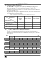
The following commands (as defined in Table 12) are used to switch between
ASCII protocols and Protocol 2000:
Table 12: RS-232 Commands for Selecting Different Protocols
To Protocol
Protocol
2000
Generic Protocol
Sierra Protocol
0x38 0x82 0x81 0x81
0x38 0x81 0x81 0x81
From Protocol
Protocol 2000
Generic Protocol
A1<Enter>
Sierra Protocol
*CHANGE HEX!
10.1
A2<Enter>
*CHANGE NORT!
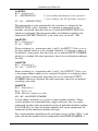
Kramer 2000 Protocol Supported Subset
This RS-232 communication protocol uses four bytes of information as
defined below. The default data rate is 9600 baud, with no parity, 8 data bits
and 1 stop bit.
MSB
LSB
DESTINATION
INSTRUCTION
0
D
N5
N4
N3
N2
N1
N0
7
6
5
4
3
2
1
0
1
I6
I5
I4
I3
I2
I1
I0
7
6
5
4
3
2
1
0
1
O6
O5
O4
O3
O2
O1
O0
7
6
5
4
3
2
1
0
1
OVR
X
M4
M3
M2
M1
M0
7
6
5
4
3
2
1
0
1st byte
INPUT
2nd byte
OUTPUT
3rd byte
MACHINE NUMBER
4th byte
17
Communication Protocols
1st BYTE:
Bit 7 – Defined as 0.
D – “DESTINATION”:
0 - for sending information to the switchers;
1 - for sending to the PC (from the switcher).
N5…N0 – “INSTRUCTION”
The function that is to be performed by the switcher(s) is defined by the
INSTRUCTION (6 bits). Similarly, if a function is performed via the
machine’s keyboard, then these bits are set with the INSTRUCTION NO.,
which was performed. The instruction codes are defined according to the
table below (INSTRUCTION NO. is the value to be set for N5…N0).
2nd BYTE:
Bit 7 – Defined as 1.
I6…I0 – “INPUT”.
When switching (i.e., instruction codes 1 and 2), the INPUT (7 bits) is set as
the input number which is to be switched. Similarly, if switching is done via
the machine’s front-panel, then these bits are set with the INPUT NUMBER
which was switched. For other operations, these bits are defined according to
the table.
3rd BYTE:
Bit 7 – Defined as 1.
O6…O0 – “OUTPUT”.
When switching (i.e., instruction codes 1 and 2), the OUTPUT (7 bits) is set
as the output number which is to be switched. Similarly, if switching is done
via the machine’s front-panel, then these bits are set with the OUTPUT
NUMBER which was switched. For other operations, these bits are defined
according to the table.
4th BYTE:
Bit 7 – Defined as 1.
Bit 5 – Don’t care.
OVR – Machine number override.
M4…M0 – MACHINE NUMBER.
Used to address machines in a system via their machine numbers. When
several machines are controlled from a single serial port, they are usually
configured together with each machine having an individual machine number.
If the OVR bit is set, then all machine numbers will accept (implement) the
command, and the addressed machine will reply.
For a single machine controlled via the serial port, always set M4…M0 = 1, and
make sure that the machine itself is configured as MACHINE NUMBER = 1.
18
KRAMER: SIMPLE CREATIVE TECHNOLOGY
Communication Protocols
10.1.1
Use of Kramer Machines
A router may be represented via the Kramer protocol as a maximum of two
machines. Based on the largest supported, 8 level switcher, the levels
correspond accordingly:
Level
1
2
3
4
5
6
7
8
Machine #
1
2
1
2
1
2
1
2
Function
Video
Video
Audio
Audio
RGB Mute
RGB Mute
Audio Levels
Audio Levels
Parameter Terminology:
Setups - Setup # 0 refers to the present switcher status. Setup # 1 and higher
are the settings saved in the switchers memory, (i.e., those used for store and
recall).
Bi-Directional - specifies a bi-directional command. If the switcher receives
the code, it will perform the instruction; if the instruction is performed, the
switcher will use the same codes for its response.
10.1.2
Command Details
“Switch Video”: Switch Video Crosspoint”
Request: 0x01 <input> <output> <machine>
Response: 0x41 <input> <output><machine>
Action: Set output to input
The “Switch Video” command is used to request that a connection be made.
Input and output are specified in hexadecimal notation. If 0 is specified for
output, all outputs will be switched to the specified input. If 0 is specified for
input, the specified output will be disconnected (Video Mute). Bi-Directional
command example:
Command To Switcher
Response From Switcher
Command
0x01 0x85 0x88 0x81
0x41 0x85 0x88 0x81
Meaning
Connect video input 5 to output 8
Video input 5 connected to output 8
19
Communication Protocols
“Switch Audio”: Switch Audio Crosspoint”
Request: 0x02 <input> <output> <machine>
Response: 0x42 <input> <output><machine>
Action: Set output to input
The “Switch Audio” command is used to request that a connection be made.
Input and output are specified in hexadecimal notation. If 0 is specified for
output, all outputs will be switched to the specified input. If 0 is specified for
input, the specified output will be disconnected (Audio Mute). Bi-Directional
command example:
Command To Switcher
Response From Switcher
Command
0x02 0x85 0x88 0x81
0x42 0x85 0x88 0x81
Meaning
Connect audio input 5 to output 8
Audio input 5 connected to output 8
“Request Video Output Status”
Request: 0x05 <setup#> <output> <machine>
Response: 0x45 <setup#> <input><machine>
Action: Request status of Output
The “Request Video Output Status” command is used to request the current
input connected to a specified output. This allows clients to poll the current
status of the switcher. Bi-Directional command example:
Command To Switcher
Response From Switcher
Command
0x05 0x80 0x88 0x81
0x45 0x80 0x85 0x81
Meaning
Request video input on output 8
Video input 5 is connected
“Request Audio Output Status”
Request: 0x06 <setup#> <output> <machine>
Response: 0x46 <setup#> <input> <machine>
Action: Request status of Output
The “Request Audio Output Status” command is used to request the current
input connected to a specified output. This allows clients to poll the current
status of the switcher. Bi-Directional command example:
Command
Command To Switcher
Response From Switcher
20
0x06 0x80 0x88 0x81
0x46 0x80 0x85 0x81
Meaning
Request video input on output 8
Video input 5 is connected
KRAMER: SIMPLE CREATIVE TECHNOLOGY
Communication Protocols
Setup Save”: Store / Delete Video Status
Request: 0x03 <setup#> <options> <machine>
Response: 0x43 <setup#> <options> <machine>
Action: Saves or deletes a Setup
The “Setup Save” command can be used to either save a setup based on the
current switcher status, or to erase an existing setup.
Options:
1 – Save
0 – Delete
Bi-Directional command example:
Command To Switcher
Response From Switcher
Command
0x03 0x81 0x81 0x81
0x43 0x81 0x81 0x81
Meaning
Save current status to setup location 1
“Setup Recall”
Request: 0x04 <setup#> 0x00 <machine>
Response: 0x44 < setup#> 0x00 <machine>
Action: Recalls a setup to the active status
The “Setup Recall” command is used to recall an existing setup. BiDirectional command example:
Command To Switcher
Response From Switcher
Command
0x04 0x81 0x80 0x81
0x44 0x81 0x80 0x81
Meaning
Recall setup location 1
Setup location 1 recalled
“Breakaway Setting”: Audio follows video
Request: 0x08 <command> <value> <machine>
Response: 0x48 <command> <value> <machine>
Action: Sets breakaway switching behavior
The “Breakaway Setting” runs in two command modes. Specifying a 0 for the
command parameter gives you value options 0 for “Audio-Follows-Video”
and 1 for “Audio Breakaway”. Specifying a 1 for the command parameter
gives you value options 0 for “Follow Mode” and 1 for “Normal Mode”.
Follow mode is used when several different types of routers (RS-422,
AES/EBU etc.,) will all follow each other, not just video and audio units. BiDirectional command example:
Command
Command To Switcher
Response From Switcher
0x08 0x80 0x80 0x81
0x48 0x80 0x80 0x81
Meaning
Enables “Audio follow video” mode
“Audio follow video” enabled
21
Communication Protocols
“Request Breakaway Setting”
Request: 0x0b <setup#> <value> <machine>
Response: 0x4b <setup#> <response> <machine>
Action: Request breakaway switching setting
The “Request Breakaway Settings” command is used to poll either the current
breakaway configuration of the switcher, or a setup breakaway configuration.
Specifying a value parameter of 0 requests current audio breakaway setting,
and a value parameter of 1 requests the “follow” setting. Breakaway
switching / follow is stored in setups. Example:
Command To Switcher
Response From Switcher
Command
0x0b 0x80 0x80 0x81
0x4b 0x80 0x81 0x81
Meaning
Request current breakaway setting
Audio currently in breakaway mode
“Error Response”
Request: Not Valid
Response: 0x50 0x00 <error> <machine>
Action: Response sent to client from switcher
The “Error Response” is used by the switcher to send error messages to the
client. An error code is returned to the PC if an invalid instruction code was
sent to the switcher, or if a parameter associated with the instruction is out of
range (e.g., trying to save to a setup greater than the highest one, or trying to
switch an input or output greater than the highest one defined). Reception of
this code by the switcher is not valid. The error value can be any of the
following values:
Error:
0 – Error
1 – Invalid Instruction
2 – Out of Range
3 – Machine Busy
Example:
Command
Command To Switcher
Response From Switcher
22
0x50 0x80 0x82 0x81
Meaning
Out of Range error message
KRAMER: SIMPLE CREATIVE TECHNOLOGY
Communication Protocols
“Store Audio Status”
Request: 0x13 <setup#> <value> <machine>
Response: 0x53 <setup#> <value> <machine>
Action: Saves current audio status to specified setup
The “Store Audio Status” is used to manage audio status in setups. Specifying
a value of 0 for “value” will store the existing audio crosspoint status to a
specified setup number. Specifying a value of 1 for “value” will delete the
current audio information stored in the specified setup. This command will
overwrite any existing audio settings in the specified setup. Example:
Command To Switcher
Response From Switcher
Command
0x13 0x85 0x80 0x81
0x53 0x85 0x80 0x81
Meaning
Store current audio status to setup 5
Audio setup 5 stored
“Recall Audio Status”
Request: 0x14 <setup#> 0x00 <machine>
Response: 0x46 <setup#> 0x00 <machine>
Action: Restores audio status from specified setup
The “Recall Audio Status” command loads the audio settings in a specified
setup to the current switcher crosspoints. Example:
Command
Command To Switcher
Response From Switcher
Meaning
0x14 0x85 0x80 0x81
0x54 0x85 0x80 0x81
Recall audio setup 5
Audio setup 5 recalled
“Set Audio Parameter”
Request: 0x16 <input/output> <value> <machine>
Response: 0x56 <input/output> <value> <machine>
Action: Sets an audio parameter of a specified input/output
The “Set Audio Parameter” command is used to directly set a parameter on an
input or output. This command is precluded by an “Audio Parameter
Settings” command, used to set further properties for this command. BiDirectional command example:
Command
Command To Switcher
Response From Switcher
0x16 0x85 0xff 0x81
0x56 0x85 0xff 0x81
Meaning
Sets Audio Gain to 127 on in/out 5
In/out 5 has a value of 127
23
Communication Protocols
“Request Audio Parameter”
Request: 0x19 <input/output> 0x00 <machine>
Response: 0x59 <input/output> <value> <machine>
Action: Request an audio parameter of a specified input/output
The “Request Audio Parameter” command is used to retrieve a parameter on
an input or output. This command is precluded by an “Audio Parameter
Settings” command, used to set further properties for this command.
Example:
Command To Switcher
Response From Switcher
Command
0x19 0x85 0x00 0x81
0x59 0x85 0xff 0x81
Meaning
Request audio parameter for in/out 5
In/out 5 has a value of 127
“Increase / Decrease Audio Parameter”
Request: 0x18 <input/output> <value> <machine>
Response: None
Action: Increases or decreases a specified audio parameter
The “Increase / Decrease Audio Parameter” command is used to adjust input
or output values on the left, right, or both audio channels. This command is
precluded by an “Audio Parameter Settings” command, used to set further
properties for this command. Use the table below for value options.
Value:
0 – Increase Output
1 – Decrease Output
2 – Increase Left Output
3 – Decrease Left Output
4 – Increase Right Output
5 – Decrease Right Output
6 – Increase Input
7 – Decrease Input
8 – Increase Left Input
9 – Decrease Left Input
10 – Increase Right Input
11 – Decrease Right Input
Example:
Command To Switcher
Response From Switcher
24
Command
0x18 0x85 0x80 0x81
Meaning
Increase output value on output 5
KRAMER: SIMPLE CREATIVE TECHNOLOGY
Communication Protocols
“Audio Parameter Settings”
Request: 0x2A <input bits> <value> <machine>
Response: None
Action: Set Parameters for the next command
The “Audio Parameter Settings” command is used to provide further
information for the “Request Audio Parameter”, “Increase / Decrease Audio
Parameter”, and “Set Audio Parameter” commands. Use the table below for
input bit and value options.
Input Bits:
0 – (0 = Input; 1 = Output)
1 – 1 = Left
2 – 1 = Right
Value:
0 – Gain
Example:
Command To Switcher
Response From Switcher
Command
0x2a 0x86 0x80 0x81
Meaning
Selected Gain on left & right input
“Set Auto-Save”
Request: 0x39 <save> 0x00 <machine>
Response: 0x79 <save> 0x00 <machine>
Action: Enable / disable auto save feature
The “Set Auto-Save” command is used to disable the saving of switcher
status at power down. This value is stored in volatile memory. At each
startup, auto set is automatically enabled. If bits 3 and 4 are set in the save
parameter, auto save will be enabled.
Save Bits:
Bit 3 – (1 = No Save)
Bit 4 – (1 = Save)
Example:
Command To Switcher
Response From Switcher
Command
0x2a 0x84 0x80 0x81
0x79 0x84 0x80 0x81
Meaning
Enable Auto Save
Auto Save Enabled
“Execute Loaded Data”
Request: 0x3A <setup#> <value> <machine>
Response: None
Action: Commits current cached crosspoint information
25
Communication Protocols
The “Execute Loaded Data” command is used in conjunction with the “Load
Video Data” and “Load Audio Data” commands to commit loaded crosspoint
information to the actual running status, or to a specified setup location.
Setting the “setup #” parameter to 0 writes cached crosspoint information to
running status.
Value:
1 – Take
2 - Cancel
Example:
Command To Switcher
Response From Switcher
Command
0x3a 0x85 0x81 0x81
Meaning
Store current cached info to setup 5
“Load Video Data”
Request: 0x3B <input> <value> <machine>
Response: None
Action: Cache video crosspoint changes for later execution
The “Load Video Data” command is used to write a crosspoint change into
cache for later recall using the “Execute Loaded Data” command. The “input”
parameter can be a specified input to set (0 = Disconnect), or can be set to a
value of 127 to specify a setup location. Depending on the value set for
“input”, “value” is either a video output (0 = All Outputs), or a setup location.
Example:
Command To Switcher
Response From Switcher
Command
0x3b 0xff 0x85 0x81
Meaning
Load setup 5 video data into cache
“Load Audio Data”
Request: 0x3C <input> <value> <machine>
Response: None
Act Action: Cache audio crosspoint changes for later execution
The ”Load Audio Data” command is used to write a crosspoint change into
cache for later recall using the “Execute Loaded Data” command. The “input”
parameter can be a specified input to set (0 = Disconnect), or can be set to a
value of 127 to specify a setup location. Depending on the value set for
“input”, “value” is either an audio output (0 = All Outputs), or a setup
location. Example:
Command To Switcher
Response From Switcher
26
Command
0x3c 0xff 0x85 0x81
Meaning
Load setup 5 audio data into cache
KRAMER: SIMPLE CREATIVE TECHNOLOGY
Communication Protocols
“Define Machine”
Request: 0x3D <command> <options> <machine>
Response: 0x7D <command> <response> <machine>
Action: Gets machine physical configuration information
The “Define Machine” command is used to request information about a
specified machine’s physical configuration. See “command” and “options”
below for specific configuration information.
Command:
1 – Number of inputs
2 - Number of outputs
3 – Number of setups
Options:
1 – For video
2 – For audio
Command To Switcher
Response From Switcher
Command
0x3d 0x81 0x82 0x81
0x7d 0x81 0x90 0x81
Meaning
Requests the number of audio inputs
16 inputs
27
Communication Protocols
1
10.2
Sierra Video Systems (SVS) RS-232 Compatible Protocol
Target hardware application: the protocol is designed to be compatible with
most existing applications that have driven the RS232 port on SVS routers. In
some cases commands have been shortened and should be compatible with all
SVS external drivers. The protocol only uses one command format to set
crosspoints, on format to load setups and one for the structure of all reply
messages.
10.2.1
Command Details I
"Clear": Clear Matrix
“Config” Configure system (requires 4 digit password)
“Change” Change from this protocol to another protocol
"X": Connect Crosspoint
"D": Delay Vertical Sync Intervals
"P": Setup a Salvo Connect Sequence
"T": Trigger a Salvo Connect Sequence
“A” Audio gain controls
“M” RGB Mute switching time
"S": Status Inquiry
"U": Automatic Output Change Reporting On/Off
“?” Query
“E” Error messages
Generic Protocol:
Commands are sent to a routing switcher in a group called a command string.
A command string can contain zero or more commands, limited only by the
size of the receive buffer of the router.
A command string consists of a leader asterisk character, zero or more
commands, and a trailer character, an exclamation mark. When a command
string is received, it is not acted upon until the final trailer character (!) of the
command string is received. At that time, the routing switcher executes the
commands within the string.
The protocol uses only 7-bit ASCII characters. The 8th bit of received
characters is treated as if it is 0. Alphabetic characters within the command
string may be in either upper-case or lower-case letters. The router always
sends upper case characters. When sending commands to the router, SPACE
characters are optional, but if used should only appear before and after each
individual command and NOT embedded within an individual command.
1 A Kramer Electronics company
28
KRAMER: SIMPLE CREATIVE TECHNOLOGY
Communication Protocols
Just before the router begins executing a command string, it sends a leader
character (asterisks) to the host. As it executes the commands, some
commands call for a response back to the host. Many of these strings contain
<CR> characters within the string in order to make the message more human
readable when viewed as raw data as would be the case when emulating a
terminal. Software written to drive these routing switchers may ignore all
spaces and <CR> characters in reply strings. After the command string has
been executed, the routing switcher returns the string " **OK!! " followed by
a trailer character (!!) and a <CR> (carriage return, ASCII 0D) character, to
the host. This indicates that the command has executed successfully. The
simplest possible command string would be:
**!!
which consists of the leader and trailer characters but no commands between
them. This command string would generate the response:
**OK!!<CR>
All responses from the router to the host begin with the asterisk character and
end with the exclamation character. In addition many response strings end
with a <CR> character. Status messages for multiple outputs from the router
to the host are delimited with a <CR> at the end of the data for each output
and before the beginning of data for the next output. When viewing the
response this produces easy to read data in columns. When read as part of a
driver program, these <CR> characters can be ignored if desired.
10.2.2
Command Details II
"Clear": Clear Matrix
Request: **CLEAR!!
Response: **OK!!<CR>
Action: Clear entire router matrix.
The command "CLEAR" requests that the switch matrix be cleared so that all
outputs are disconnected from inputs (in routers where this is possible) or else
all outputs at all levels have input #1 as their source (when disconnecting is
not possible). If output locks are supported, all output locks are removed by
this command. This command can take several seconds to execute (depending
on the size of the switch matrix), and therefore the OK response at the end of
the command string could be quite late. In order to help ensure that this
command isn'
t accidentally executed, it requires four additional characters
following the "C" character, to spell out the word "CLEAR" in full.
For example, the command:
**CLEAR!!
29
Communication Protocols
would clear the matrix, and when finished, the following response would be
generated:
**OK!!<CR>
This command only clears the crosspoint settings. Any data stored in the
setup memory space or the values from the audio gains are not changed by
this command. In order to clear or reset these values, the following additional
types or clear commands are used:
"Config": Configure Matrix
Request: **CONFIG1234 , oo , ii , l , f1 , f2!!
The Configuration command is protected with a four-digit password (1234 in
the above example is a placeholder). The command tells the software the size
of the switching matrix, the number of levels and several special functions
such as the assignment of levels used for RGB muting and audio gain
controls. Like the clear commands explained above, the configure command
must begin with the six letters CONFIG, upper or lower case and without
spaces between the letters. The present software will accept output values
from 1 to 64 (oo) and input values from 2 to 64 (ii) and level values up to 8
(l). f1 and f2 are eight bit (0-255) flag values that can be used to define
special system operations. They are normally sent as 000 and 000.
The Config command must have all six arguments in order to affect a change
in the router configuration.
Note: changing the router configuration with this command does not change
the contents of the non-volatile memory that stores the router’s current state
or the contents of the setup registers. Most routers are based on an eight level
scheme. When the configuration flags are both set to 000 and 000, the eight
levels are used as follows:
Level 1. First video level. If the router is an RGBHV router this level is used
for RGBHV.
Level 2. Second video level. This video level can be another RGBHV level or
it can be composite video or SDI video, etc.
Level 3. First stereo audio level. The crosspoint hardware will switch left and
right channels together as one level.
Level 4. Second stereo audio level. The crosspoint hardware will switch left
and right channels together as one level.
Level 5. Used to effect RGB mute switching in conjunction with Level 1.
Level 6. No assignment – can be used as a video or audio channel as needed.
Level 7. Used in conjunction with level 3 to effect remote control of audio
levels.
Level 8. Used in conjunction with level 4 to effect remote control of audio
levels.
30
KRAMER: SIMPLE CREATIVE TECHNOLOGY
Communication Protocols
For other uses of the eight levels and other future features, either the first or
second or both flag values will be non-zero.
When the router has received a valid Config command and after it has
reconfigured itself accordingly, the router sends the following response
message:
*CONFIGURATION <CR>
OUTPUTS (oo) <CR>
INPUTS (ii) <CR>
LEVELS (l) <CR>
FLAG 1(nnn)<CR>
FLAG 2(nnn)!
In addition when the router is powered up the message above is sent with one
of two added lines:
Crosspoints restored from memory!
or
Crosspoint restore failed!
The last flag in this situation is followed by a <CR> in place of the !
character.
"Change": Change protocol
Request: **CHANGE HEX!!
or
**CHANGE NORT!!
The Change commands are used to exit from this protocol to either the
Kramer 2000 protocol or the Generic protocol. When used with the Kramer
2000 protocol the system appears as a maximum of two machines.
Tentatively the eight levels are:
Level 1: Machine 1 video
Level 2: Machine 2 video
Level 3: Machine 1 audio
Level 4: Machine 2 audio
Level 5: Machine 1 RGB Mute
Level 6: Machine 2 RGB Mute
Level 7: Machine 1 audio levels
Level 8: Machine 2 audio levels
When using the “NORT” protocol the system appears as only levels one
through four as follows:
31
Communication Protocols
Level 1: Video crosspoint control
Level 2: Audio crosspoint control
Level 3: RGB Mute
Level 4: Audio levels
"X": Connect Crosspoint
Request: **X!! out,in,lvl
Response: **OK!! or an ‘Update’ message when updates are turned on.
Action: Make a connection to an output on a level.
The command "X" is used to request that a connection be made. It must be
followed by an output number, a comma, an input number, a comma, and a
level number(s).
For example, the command:
**X24,13,2!!
says that a connection is to be made between output 24 and input 13 on level
2. If the level number is specified as "0", this means that the connection is to
be made on all levels (AFV).
For example, the command:
**X8,3,0!!
says that a connection is to be made between output 8 and input 3 on all
levels.
The above structure of the x command is 100% compatible with all SVS
routers. Expanding on this, this protocol can address more than one level
identity in a single message. For example:
**X8,3,2,3,4!!
Tells the router to switch output 8 to input 3 on levels 2, 3 and 4 while
leaving level 1 unchanged.
Or
**X8,3,2,3,4X8,7,1!!
Tells the router to switch output 8 to input 3 on levels 2, 3, 4 and to switch
level 1 to input 7.
"D": Delay Vertical Sync Intervals
Request: !D numsyncs*
Response: **OK! !<CR>
Action: Delay a number of vertical sync intervals.
The command "D" is used to delay before continuing execution of the
commands that follow. It must be followed by a number giving the number of
vertical sync intervals by which to delay. If the number is 1, the delay will be
32
KRAMER: SIMPLE CREATIVE TECHNOLOGY
Communication Protocols
to the VERY NEXT vertical sync interval. If the number is 0, no delay
occurs. The number must be no larger than 255. Note that this command will
also delay the time at which the remaining command responses and the trailer
character are returned to the host. For example, the command:
**X1,5,0 D200 D100 X1,6,0 S!!
says that input 5 is to be connected to output 1 on all levels, then a delay of
300 (=200+100) sync intervals is to occur, then input 6 is to be connected to
output 1 on all levels, then a status response is to be returned. Note: the
spaces shown in the string above are optional.
It is generally recommended that the host computer be responsible for timing
the initiation of commands, rather than using this command to do the job. The
host computer can simply send the appropriate commands at the appropriate
times. The "P" and "T" commands described below can aid in ensuring that
lengthy connect sequences aren'
t delayed due to the time it takes to send them
to the router.
"P": Setup a Salvo Connect Sequence
Request: **P reg connect connect ... ~!!
Response: **OK!!<CR>
Action: Store a list of connect commands in a salvo register.
The command "P" is used to set up a salvo, which is a series of connect
commands for later execution with the "T" command (see below). It must be
followed by a register letter from A to Z giving the register into which the
connect sequence is to be stored, followed by zero or more connect
commands followed by a "~" (tilde) character. For example, the command:
**PB X2,5,0 x1,7,0 ~ !!
says that two connect commands (output 2 to input 5 AFV, and output 1 to
input 7 AFV) are to be stored into salvo register B (i.e. register 2).
The connect commands do not take effect until the register is triggered using
the "T" command below.
The contents of each setup register is determined by one message string. If a
second string is sent to the same register, the first message is ignored and
overwritten by the second message.
To clear a setup the host can send:
**PB ~ !!
The tilde in the above examples is for compatibility with existing SVS
drivers. It may be omitted if desired without causing errors. Likewise the
spaces in the above command string examples may be omitted.
33
Communication Protocols
"T": Trigger a Salvo Connect Sequence
Request: **T reg!!
Response: **OK!!<CR>
Action: Trigger a list of connect commands stored in a salvo register.
The command "T" is used to trigger a previously set up salvo (set using the
"P" command above). It must be followed by a register letter from A to Z
For example, the command:
**TB D180 TC!!
says to trigger salvo register B, delay 180 sync intervals, then trigger salvo
register C. When the register is triggered, this means that the connect
commands stored in it take effect.
When the Updates mode is turned on and a salvo connect sequence is
triggered the only reply is as noted above.
If the command:
**TB? D180 TC?!!
Is sent to the router instead, two full crosspont status messages will be sent.
Each with its own * and ! delimiters. If setup C contains changes to setup B,
the two status reports will indicate both switch changes to the same output
buses.
“A” : A Command Audio Gain Control
The “A” commands are used to change the audio input or output gain values.
The gain values can be set to an absolute value, incremented up or down.
In a A command the A must be followed by an I or O to designate input or
output then the number of that input or output followed by a comma. Then a
L or R to designate left or right. This combination is then either followed by a
U to indicate increment up one step, a D to indicate increment down by one
step or a number between 0 and 255 indicating the absolute value of the gain.
Where 127 is unity gain, 0 is mute or minimum gain and 255 maximum gain.
Like all other commands the A command either ends with a <CR> or it can
be strung in a multiple command string, which may include multiple gain
settings executed in a ‘stack-and-load’ sequence.
Example:
**AI2,L150!! means Input 2, left channel set to a gain of 150.
Or:
**AO4,LD!! means decrease the gain of output 4 left channel by 1/256th.
34
KRAMER: SIMPLE CREATIVE TECHNOLOGY
Communication Protocols
Changes in audio gains are NOT reported when Updates is turned on. Doing
so would cause the router to send to the host long strings as panel operators
turned up and down the volume. The query (?) command works for the A
commands in the same way it operates on the X commands.
When the configuration message flags are both set to 000, the action of these
gain commands is upon the audio channel connected to hardware level 3 and
effected via level 7.
If there is more than one level with variable audio, possibly levels three and
four, then a different configuration flag configuration if required and the A
command must specify which audio path levels are being addressed.
M Command (RGB Mute delay)
Purpose: The M command is used to set the delay time for RGB ‘mute’
switching. It can be set to a different value for each output. This parameter is
stored in non-volatile memory when the power is turned off. It is not stored in
the individual setup registers.
Example:
**M3,5!! means switching on output bus 3 will have a 2.5 second mute delay.
The delay is in increments of 1/2 second. A value of 0 means there is no RGB
delay mode and the RGBHV channels all switch together to the new source.
Like the A command the M command, with configuration flag values 000,000
operates levels 1 and 5 to achieve control of the RGB and HV channels.
For other configuration flag values, the M command may require the
inclusion of which level is being controlled.
"S": Status Inquiry for Crosspoints
Request: **S!!
The command "S" requests that matrix status information be returned to the
host. The reply from the router to the host is with a list of all outputs and all
inputs connected to the outputs.
The number of lines of data in the list is equal to the number of outputs as set
up by the Configuration command explained later.
The number of columns in the list is also set by the Configuration command.
The configuration command determines the number of levels.
35
Communication Protocols
The default sequences across each line of the status message is:
Output number – comma
level 1 input number – comma
.
.
.
level 8 input number– comma <CR>
At the beginning of the first line the router sends an asterisk and after the last
line the router sends an exclamation !.
"SA": Status Inquiry for Audio gains
Request: **SA!!
The command "SA" requests the status information for all audio gain values
be returned to the host. The reply from the router to the host is with a list of
all output and all input gain values. The number of lines of data in the list is
equal to the number of outputs plus the number of inputs as set up by the
Configuration command explained later. The number of columns in the list is
also set by the Configuration command. The configuration command
determines the number audio channels. The default sequences across each
line of the status message is:
Output number – comma
left level– comma
right level<CR>
Then:
Input number – comma
left level– comma
right level<CR>
At the beginning of the first line the router sends an asterisk and after the last
line the router sends an exclamation !.
The example above is for a typical system with one stereo audio path. For
systems with more than one stereo audio path, each line within the list will
have the next channel’s left and right gains and so on for whatever number of
channels the system may have. The audio level is a number from 0 to 255.
When a system with no audio gain registers is queried by the “SA” command
the router may respond with: !* which indicates that there is no data
36
KRAMER: SIMPLE CREATIVE TECHNOLOGY
Communication Protocols
"U": Automatic Output Change Reporting On/Off
Request: **U!! { 0 | 1 | 2 }
Response: (none)
Action: Turn automatic output change reporting off or on.
The command "U" turns on or off the automatic sending of output change
reports. The command letter must be followed by either a number 0, 1, or 2 to
specify the new automatic change report state, as follows:
* 0: Automatic output change reporting is turned off.
* 1 or 2: Automatic output change reporting is turned on, and crosspoint
change commands immediately report changed.
Output change reports are automatic messages sent to the host whenever an
output'
s crosspoint status (i.e. connected source) is change via either the local
control panel or via some other port.
Changes are reported in the same structure as described for the S command,
except there may be fewer lines to the report.
For example, the command:
**U1!!
turns on automatic output change reporting. The format of crosspoint
reporting is the same for U, S and ? messages.
"?": Query command
Request: **X5?!!
Response: **5,3,3,3,3!!<CR>
Action: The status of the previous command is requested.
The "? " Query can be added in a command string to cause a response back to
the host with selected status information.
The ? command can be placed in a shortened X command as illustrated
bellow to give the status of a single output.
**X5?!!
The ? command can be put at the end of a valid X command to give the status
of a switch after it is made. Such as
**X5,4,1?!!
In which case the response will confirm that that the above crosspoint
selection has been effected. Or it can be used multiple times in a command
string:
**X6?X5,4,1?!!
37
Communication Protocols
Is responded to with two messages that will report the status of output 6 and
then output 5.
**PA?!!
Will cause a response string in the same format as used for an S command
response, except the data reported is the contents of a setup register A rather
than a the status of the current crosspoint configuration. These messages may
only contain as many lines of configuration information as stored in the setup
register and the order presented is the order in which they have been loaded
into the setup.
"E": Error messages (from the router to the host) command
Response: **E1!!<CR>
The router produces a number of possible error messages. They are:
E1 means invalid command (other than the specific errors listed below)
E2 means invalid input number
E3 means invalid output number
E4 means invalid configuration password
E5 means invalid level number
E6 through E9 reserved for future use
38
KRAMER: SIMPLE CREATIVE TECHNOLOGY
Communication Protocols
10.3
Generic Protocol Supported Subset
This RS-232 communication protocol uses a default data rate of 9600 baud, 8
data bits, and 1 stop bit.
10.3.1
Use of Generic Machines
A router may be represented via the Kramer protocol as a maximum of two
machines. Based on the largest supported, 8 level switcher, the levels
correspond accordingly:
Level
1
2
3
4
10.3.2
Function
Video Crosspoint
Audio Crosspoint
RGB Mute
Audio Levels
Command Details
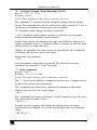
“Reconfig”: Router Manual Reconfiguration Indicator
Request: None
Response: RECONFIG<CR><LF>
Action: Indicates manual router crosspoint change has been performed via
an interface other than the serial client.
“RECONFIG” is a switcher initiated message indicating that a user has
adjusted the current configuration of the switcher by a front panel or remote
panel interface. Example:
Command
Command To Switcher
Response From Switcher
RECONFIG<CR><LF>
Meaning
Manual status change
“RGB Delay”:
Request: <delay>*<output>D
Response: Out<output> Dly<delay><CR><LF>
Action: Sets the RGB interval for switches on a specified output.
The “RGB Delay” command is used to set a delay in seconds, from 0 to 10, in
.5 second increments.
Examples
Command To Switcher
Response From Switcher
Command
7*13D
Out13 Dly07<CR><LF>
Meaning
Set 3.5 second delay on out 13
3.5 second delay on out 13
Command To Switcher
Response From Switcher
13D
Out 13 Dly05<CR><LF>
Request delay on out 13
2.5 second delay on out 13
39
Communication Protocols
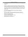
“Audio Input Gain and Attenuation”:
Request: <input>*<gain>G
Response: In<input> Aud=<dB Value><CR><LF>
Action: Sets audio gain to a positive value
Request: <input>*<gain>G
Response: In<input> Aud=<dB Value><CR><LF>
Action: Sets audio gain to a negative value
Request: <input>|G
Response: In<input> Aud=<dB Value><CR><LF>
Action: Increments audio gain by 1dB
Request: <input>|g
Response: In<input> Aud=<dB Value><CR><LF>
Action: Decrements audio gain by 1dB
The “Audio Input Gain and Attenuation” commands are used to adjust the
audio gains on specified inputs. This command is specific to input
adjustment, and cannot be used to adjust outputs. Examples:
Command To Switcher
Response From Switcher
Command
1*2G
In01 Aud=+02<CR><LF>
Meaning
Set input 1 audio gain to +2dB
Audio Gain set to +2dB
Command To Switcher
Response From Switcher
1*2g
In01 Aud=-02<CR><LF>
Set input 1 audio gain to -2dB
Audio Gain set to -2dB
Command To Switcher
Response From Switcher
5|G
In05 Aud=+03<CR><LF>
Increment audio input 5 by 1dB
Audio input 5 incremented 1dB
Command To Switcher
Response From Switcher
5|g
In07 Aud=-09<CR><LF>
Decrement audio input 5 by 1dB
Audio input 5 decremented 1dB
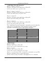
“Global Setups”:
Request: <setup>,
Response: Spr<setup><CR><LF>
Action: Saves current configuration as a setup.
Request: <setup>.
Response: Rpr<setup><CR><LF>
Action: Saves current configuration as a setup.
Request: <esc>P<setup><CR> <standard tie commands> <esc>p<CR>
Response: End Write Setup <setup><CR><LF>
Action: Creates a setup “on-the-fly” with supplied user tie commands
40
KRAMER: SIMPLE CREATIVE TECHNOLOGY
Communication Protocols
Global setups store and recall the current status of the switcher. Examples:
Command To Switcher
Response From Switcher
Command
<esc>P14<CR>
Write Setup 14 Ready<CR><LF>
Meaning
Start recording setup 14
Started recording…
Command To Switcher
Response From Switcher
1*3!
7*8%
A&V input 1 tied to out 3
Vid input 7 tied to out 8
Command To Switcher
Response From Switcher
<esc>p<CR>
End Write Setup 14<CR><LF>
Done Recording
Saved Setup 14
Command To Switcher
Response From Switcher
<esc>.<CR>
Rpr14<CR><LF>
Recalls the setup
Recalled setup 14
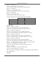
“Video Mute Commands”:
Request: <output>*1B
Response: Vmt<output>*1<CR><LF>
Action: Mutes specified output video (video off)
Request: <output>*0B
Response: Vmt<output>*0<CR><LF>
Action: Disables Mute specified output video (video on)
Request: <output>*B
Response: <on/off><CR><LF>
Action: Request video mute state of a specified output
Request: <on/off>*B
Response: Vmt1<CR><LF>
Action: Mutes / un-mutes all Video outputs
Controls muting and un-muting video outputs. Examples:
Command To Switcher
Response From Switcher
Command
2*1B
Vmt2*1<CR><LF>
Meaning
Mute output 2 video (video off)
Output 2 video off
Command To Switcher
Response From Switcher
1*B
Vmt1
Mute all video (global)
All video muted
“Audio Mute Commands”:
Request: <output>*1Z
Response: Amt<output>*1<CR><LF>
Action: Mutes specified output audio (audio off)
41
Communication Protocols
Request: <output>*0Z
Response: Amt<output>*0<CR><LF>
Action: Disables Mute specified output audio (audio on)
Request: <output>*Z
Response: <on/off><CR><LF>
Action: Request audio mute state of a specified output
Request: <on/off>*Z
Response: Amt1<CR><LF>
Action: Mutes / un-mutes all audio outputs
Controls muting and un-muting video outputs. Examples:
Command
Meaning
Command To Switcher
Response From Switcher
2*1Z
Amt2*1<CR><LF>
Mute output 2 audio (audio off)
Output 2 audio off
Command To Switcher
Response From Switcher
1*Z
Amt1
Mute all audio (global)
All audio muted
“Create Ties”:
Request: <input>*<output>!
Response: Out<output> In<input> All<CR><LF>
Action: Tie specified input to specified output (All levels).
Request: <input>*<output>&
Response: Out<output> In<input> RGB<CR><LF>
Action: Tie specified input to specified output (Level 1 Only).
Request: <input>*<output>%
Response: OutOut<output> In<input> Vid<CR><LF>
Action: Tie specified input to specified output (Level 3 Only).
Request: <input>*<output>$
Response: Out<output> In<input> Aud<CR><LF>
Action: Tie specified input to specified output (Level 2 Only).
Request: <esc>Q<input>*<output>!...<input>*<output>!<CR>
Response: Out Multi In Multi All<CR><LF>
Action: Tie specified inputs to specified outputs (All levels).
Request: <input>!
Response: Out Multi In <input> All<CR><LF>
Action: tie specified input to all outputs.
The “Create Ties” commands are used to set crosspoints on the switcher, at
one or more levels.
Examples:
42
KRAMER: SIMPLE CREATIVE TECHNOLOGY
Communication Protocols
Command
Meaning
Command To Switcher
Response From Switcher
1*3!
Out03 In01 All
Tie input 1 A&V to output 3
Output 3 tied to input 1
Command To Switcher
Response From Switcher
<esc>Q3*4!3*5!3*6!<CR>
Out Multi In Multi All
Command stack switches
Multiple outputs switched
“View Ties, Gain, Mutes, and Setups”:
Request: V/v<output>%
Response: Out<output> In<input> Vid<CR><LF>
Action: View video output tie
Request: V/v<output>$
Response: Out<output> In<input> Aud<CR><LF>
Action: View audio output tie
Request: V/v<input>G
Response: In<input> Aud=<numeric dB value><CR><LF>
Action: View gain for specified input
Request: VM/vm
Response: <execMode> <output1 input> <output2 input>…Mut<CR><LF>
Action: View all output mutes. Each position listed in the response is an
output, left =1…
Request: V/v<setup>.
Response: <output1> <output2>…Vid <output1> <output2>… Aud<CR><LF>
Action: View setup configuration (setup 0 for current config)
The “View Ties, Gain, Mutes, and Setups” commands are used to retrieve
current setup and running status information. Examples:
Command To Switcher
Response From Switcher
Command
V7%
Out07 In02 Vid<CR><LF>
Meaning
Get video input tied to output 7
Video Output 7 tied to input 2
Command To Switcher
Response From Switcher
V3$
Out03 In06 Aud<CR><LF>
Get audio input tied to output 3
Output 3 audio tied to input 6
Command To Switcher
Response From Switcher
VM
0 1 0 2 0 3…Mut<CR><LF>
View all video mutes
List of video mutes
Command To Switcher
Response From Switcher
V4G
In04 Aud=-02
Get audio gain for input 4
Gain for input 4 is -2dB
Command To Switcher
Response From Switcher
V0.
08 08 08…Vid 05
0505…Aud<CR><LF>
View current switcher status
Reports current status of each video output, then
the status of each audio output.
43
LIMITED WARRANTY
Kramer Electronics (hereafter Kramer) warrants this product free from defects in material and workmanship under the
following terms.
HOW LONG IS THE WARRANTY
Labor and parts are warranted for seven years from the date of the first customer purchase.
WHO IS PROTECTED?
Only the first purchase customer may enforce this warranty.
WHAT IS COVERED AND WHAT IS NOT COVERED
Except as below, this warranty covers all defects in material or workmanship in this product. The following are not covered
by the warranty:
1.
2.
3.
Any product which is not distributed by Kramer, or which is not purchased from an authorized Kramer dealer. If you are
uncertain as to whether a dealer is authorized, please contact Kramer at one of the agents listed in the web site
www.kramerelectronics.com.
Any product, on which the serial number has been defaced, modified or removed.
Damage, deterioration or malfunction resulting from:
i)
Accident, misuse, abuse, neglect, fire, water, lightning or other acts of nature
ii)
Product modification, or failure to follow instructions supplied with the product
iii)
Repair or attempted repair by anyone not authorized by Kramer
iv)
Any shipment of the product (claims must be presented to the carrier)
v)
Removal or installation of the product
vi)
Any other cause, which does not relate to a product defect
vii)
Cartons, equipment enclosures, cables or accessories used in conjunction with the product
WHAT WE WILL PAY FOR AND WHAT WE WILL NOT PAY FOR
We will pay labor and material expenses for covered items. We will not pay for the following:
1.
2.
3.
Removal or installations charges.
Costs of initial technical adjustments (set-up), including adjustment of user controls or programming. These costs are the
responsibility of the Kramer dealer from whom the product was purchased.
Shipping charges.
HOW YOU CAN GET WARRANTY SERVICE
1.
2.
3.
To obtain service on you product, you must take or ship it prepaid to any authorized Kramer service center.
Whenever warranty service is required, the original dated invoice (or a copy) must be presented as proof of warranty coverage,
and should be included in any shipment of the product. Please also include in any mailing a contact name, company, address, and
a description of the problem(s).
For the name of the nearest Kramer authorized service center, consult your authorized dealer.
LIMITATION OF IMPLIED WARRANTIES
All implied warranties, including warranties of merchantability and fitness for a particular purpose, are limited in duration to
the length of this warranty.
EXCLUSION OF DAMAGES
The liability of Kramer for any effective products is limited to the repair or replacement of the product at our option. Kramer
shall not be liable for:
1.
2.
Damage to other property caused by defects in this product, damages based upon inconvenience, loss of use of the product, loss
of time, commercial loss; or:
Any other damages, whether incidental, consequential or otherwise. Some countries may not allow limitations on how long an
implied warranty lasts and/or do not allow the exclusion or limitation of incidental or consequential damages, so the above
limitations and exclusions may not apply to you.
This warranty gives you specific legal rights, and you may also have other rights, which vary from place to place.
NOTE: All products returned to Kramer for service must have prior approval. This may be obtained from your dealer.
This equipment has been tested to determine compliance with the requirements of:
EN-50081:
"Electromagnetic compatibility (EMC);
generic emission standard.
Part 1: Residential, commercial and light industry"
EN-50082:
"Electromagnetic compatibility (EMC) generic immunity standard.
Part 1: Residential, commercial and light industry environment".
CFR-47:
FCC Rules and Regulations:
Part 15: “Radio frequency devices
Subpart B – Unintentional radiators”
CAUTION!
Servicing the machines can only be done by an authorized Kramer technician. Any user who makes changes or modifications to the unit
without the expressed approval of the manufacturer will void user authority to operate the equipment.
Use the supplied DC power supply to feed power to the machine.
Please use recommended interconnection cables to connect the machine to other components.
44
KRAMER: SIMPLE CREATIVE TECHNOLOGY
For the latest information on our products and a list of Kramer
distributors, visit our Web site: www.kramerelectronics.com,
where updates to this user manual may be found.
We welcome your questions, comments and feedback.
Safety Warning:
Disconnect the unit from the power supply before
opening/servicing.
Caution
Kramer Electronics, Ltd.
Web site: www.kramerelectronics.com
E-mail: [email protected]
P/N: 2900-000024 REV 4