1
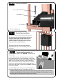
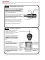
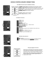
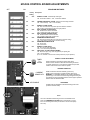
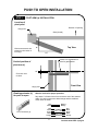
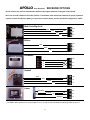
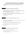
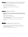
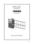
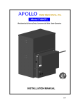
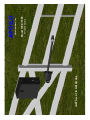
03/07 INSTALLATION MANUAL Swing Gate Operator Model 1500 / 1600 Gate Operators, Inc. APOLLO CONTENTS Safety Precautions ................................................... 3 Applications .............................................................. 4 Pre-Installation Checklist ........................................ 5 Parts Identification ................................................... 6 Operator Installation ................................................ 7-11 Pivot Arm Installation Actuator Installation Control Box Installation Connecting the Actuator Gate Bracket Installation Limit Switch Adjustment Control Board Connections Control Board Adjustments Push to Open Installation .......................................... 12 Radio Receiver Options ............................................. 13 Troubleshooting guide .............................................. 14-16 Warranty .................................................................... 2 17 IMPORTANT SAFETY INSTRUCTIONS WARNING - To reduce the risk of injury or death: READ AND FOLLOW ALL INSTRUCTIONS. Installation should be performed by a professional installer. Required welding should be performed by a qualified welder. Should electricity be required, use a certified electrician only. Any device that requires 120 Volts AC should be U.L. approved. Review with the owner all safety concerns including: Do not operate the gate unless area around gate is in full view. Never let children operate or play with gate controls. Keep the remote control away from children. Always keep people and objects away from the gate. NO ONE SHOULD CROSS THE PATH OF THE MOVING GATE. Periodically test the obstruction sensitivity to assure safe and proper operation. Do not test sensitivity by standing between the gate and the hinge or stop post. The “CAUTION AUTOMATIC GATE” signs should be clearly visible from both sides of the gate. Always insure that the gate has closed securely before leaving area. Arrange with local fire and law enforcement for emergency access. Use the emergency release only when the gate is not moving. A secondary entrapment device such as loop detectors, edge switches, and beam detectors are highly recommended and required to meet the UL325 standard. Install control devices such as keypads far enough away (5 feet or further) from any moving parts of the operator and gate to prevent possible injury. Do not install control box where the gate can come in contact with person using the push button on side of control box. Always disconnect the battery or power source when making adjustments or repairs to any part of the gate or operator. All rollers should be covered to prevent injury. KEEP GATES PROPERLY MAINTAINED. Read the owner’s manual. Have a qualified service person make repairs to gate hardware. The entrance is for vehicles only. Pedestrians must use separate entrance. Test the gate operator monthly. The gate MUST reverse on contact with a rigid object or stop when an object activates the non contact sensors. After adjusting the force or limit of travel, retest the gate operator. Failure to adjust and retest the gate operator properly can increase the risk of injury or death. SAVE THESE INSTRUCTIONS. 3 APPLICATIONS The Apollo Model 1500/1600 Swing Gate Operator is designed to handle swing gates up to 16 feet in length and 600 pounds each. A professional fence or gate dealer is recommended to assure proper installation. Apollo Gate Operators are available only through qualified dealers with an outstanding reputation in the fence and gate industry. These dealers will be able to recommend the proper equipment for particular applications. Apollo Gate Operators are 12 Volt DC (Direct Current) powered. A 12 Volt sealed battery (33ampere hour minimum) with connecting posts located on the top is recommended. There are several advantages with 12 Volt DC systems: Low voltage virtually eliminates risk of electrical shock. Battery powered operators provide up to 200 operations in the event of power outages. The battery may be recharged with a trickle charger or by solar energy (eliminating the need for costly trenching to remote entrances). If a trickle charger is used and a standard electrical outlet is not readily available, a licensed electrician will be required for proper electrical hook up. The following table should be used as a guide for capacity of operation of operators only, additional options may reduce the the daily usage. Please note that the charge capability of solar panels will vary with different geographical locations. Daily Cycles 1-10 5 watt solar panel 1-20 1-40 1-60 1-80 80+ * 10 watt solar panel * 20 watt solar panel (requires 5310 regulator) 30 watt solar panel (requires 5310 regulator) * * 40 watt solar panel (requires 5310 regulator) * 1.5 amp battery charger * 10 amp battery charger * Note: Double the amount of solar panels for Dual Gate Operators. 4 PRE-INSTALLATION CHECKLIST The following checklist should be used before beginning installation: Verify that the proper operator has been selected for this application. Verify proper installation and operation of the gate. 1. Are the hinges servicable? 2. Does the gate swing free and level? 3. Will the gate require a locking device? 4. Is the hinge and stop posts sturdy enough to handle the gate & operator? Determine the general location of the operator, attachment points, and solar panel (if used). 1. Is there a suitable location for the operator? 2.Can the solar panel (if used) be mounted in an unobstructed area facing south (in the northern hemisphere)? 3. Will additional solar panel cable be required? 4. Is electricity available (if required)? Consider safety and access options. Recommend if needed. 1. Will there be children or animals in the area? 2. Are safety loops, edge switches, or photo beam detectors required? 3. How can the gate be opened in emergencies? 4. How will visitors enter and exit? 5. Will vehicles (and trailers) have sufficient room off roadway to operate any control devices such as keypads? 5 PARTS IDENTIFICATION 416E Actuator with 8’ cable (416EX slave actuator with 38’ cable supplied with 1600) #11111B Control Box #10000415 Pivot Arm (2 with 1600) #10025215 Gate Bracket (2 with 1600) #1125 Hardware Kit (2 with 1600) OPTIONS #201 5 Watt Solar Panel & Bracket (optional) (2 required with 1600) #404C Automatic Battery Charger (optional) 6 #446 Bolt On Pivot Arm (optional) (2 required with 1600) OPERATOR INSTALLATION STEP 1 PIVOT ARM INSTALLATION (standard pull to open) Location of Pivot Point. Notes: PULL TO OPEN pulls gate open (actuator is extended when gate is in the closed position). PUSH TO OPEN pushes the gate open (actuator is retracted when gate is in the closed position). For PUSH TO OPEN installations see page 12. If a 400 Upgrade Kit is to be used, refer to the 400 instructions for pivot point location. The following instructions provide up to 105o of swing. Right Hand Swing Left Hand Swing Gate (closed) Direction of opening 13” 6” 13” 6” Top View Measurements are taken from the center of the hinge. Center Line of attachment point for gate bracket Vertical position of pivot arm 1/2” Pivot ArmMust be level Front View Hinge post 7 STEP 2 Actuator Installation 1/2” x 3 1/2” Hex Bolt 1/2” Washer 1/2” Lock Nut Do not over tighten nut STEP 3 Control Box Installation Mount the control box within 4 feet of the pivot arm. Do not mount the control box where the person using the push button on side of the box can come in contact with the gate. Use mounting hardware capable of supporting the weight of the control box with the battery installed. Set battery inside of control box with terminals toward the front (Do not use any battery with side terminals). STEP 4 Connecting the Actuator (s) Connect actuator cable to the “MASTER” connector on the control board. If a 1600 Dual Operator is being installed and conduit is being used under the drive (recommended), cut the slave (opposite side where control box is mounted) actuator cable about 12” from the white connector. Run the remaining cable across the drive through conduit and up through the control box. Cutoff any excess cable and splice the short piece back to the cable.* Connect to the “SLAVE” connector on the control board. MASTER Connect the RED power wire (s) to the battery positive ( + ) and the BLACK power wire (s) to the battery negative ( - ) * Instead of cutting the slave cable, remove the pins on the plug with a jeweler's common blade screwdriver or appropriate tool (the staples on the actuator shipping carton work great) ,run the cable through the conduit and reinsert the pins into the plug. 8 IMPORTANT Never weld parts to the gate or posts when the operator circuit board is powered. Doing so may damage the board beyond repair. STEP 5 GATE BRACKET INSTALLATION Activate push button on the side of the control box and extend the actuator until it stops (PULL TO OPEN only, leave actuator retracted for PUSH TO OPEN). WARNING: Do not let extension tube rotate as it extends. Do not insert fingers or tools in the hole at the end of the extension tube 1/2” x 3” Bolt 1/2” Washer (2 places) Align the hole in the end of the actuator extension tube with the holes in the gate bracket and locate gate bracket mounting position with the gate in the closed position. Weld or bolt the gate bracket to the gate using 3/8” bolts, lock washers, and nuts. 1/2” Lock Nut Tip: Tack weld or C clamp at first if uncertain about location. Run the unit through a complete cycle to insure proper operation then mount permanently . Bolt the actuator to the gate bracket as shown. STEP 6 Limit Switch Adjustment Cycle the operator and adjust limits as required. If the operator opens automatically after closing, extend less until gate remains closed. Remove limit switch end caps Do not retract the extension tube too far or the retract limit switch will not be activated. (You can depress the LED ENABLE button on the control board to see when the actuator has reached it’s limit) Extend Limit Screw 1600 Adjustments As you open and close the gates, you will notice that the slave side moves 2-3 To Extend More Turn Extend seconds slower than the master. Limit Screw CounterClockwise Tip: By welding stop tabs on the top and bottom of the master side, the two gates may now be adjusted so the slave To Extend Less Turn Extend gate will close against the stop tabs of Limit Screw the master gate and create enough Clockwise tension to prevent gates from moving Retract Limit Screw back and forth. 9 To Retract More Turn Retract Limit Screw Clockwise To Retract Less Turn Retract Limit Screw CounterClockwise 635/636 CONTROL BOARD CONNECTIONS 8 Pin White Connector (two on 636 Master & Slave) 7 8 5 6 3 4 1 2 1 ORANGE - Open Limit Input (Normally open unless gate is opened) 2 WHITE - Close Limit Input (Normally open unless gate is closed) 3 BLACK - Motor - Positive during open cycle, Negative during close cycle 4 RED - Motor - Negative during open cycle, Positive during close cycle 5 GREEN - Ground (Limit Switch Common) 6 Ground Not used 7 BLACK - Ground - Battery Negative 8 RED - Battery Positive (+12 VDC) MASTER 7 Pin Black Connectors 123 1 Edge 1 Input 2 Edge 2 Input 3 Ground 4 Ground 5 Stop Input (N/C) 3 Button Control 6 Close Input (N/O) 7 Open Input (N/O) 8 Ground 9 Ground 10 Free Exit Input (Open only for telephone entry, probes, etc.) 11 Ground 12 Under Gate or Shadow Loop Input 13 Ground 14 Safety Loop or Photo Beam Input 3 Pin Black Connectors (3) GND Ground INP Input (Activates gate when momentarily connected to ground) 12V +12 Volt Output (For powering options - 3 Amps Max.) Emergency Bypass Connector Used when the control board is not functioning. Unplug the motor harness from the Master (or Slave) Connector and momentarily insert into the Emergency Bypass Connector to open the gate. In the event the motor is not disconnected quickly enough, the blue 15 amp fuse will protect the circuit board from damage and should be replaced when the 10 original problem is fixed. 635/636 CONTROL BOARD ADJUSTMENTS OFF PROGRAM SWITCHES ON Factory Setting Description #1 OFF TIMER TO CLOSE - Automatically closes gate ON - Close timer enabled OFF - Close timer disabled #2 OFF CURRENT SENSITIVITY OPTION - Delays current sensing from start ON - 4 second delay OFF - 2 second delay #3 ON #4 OFF #5 OFF #6 OFF #7 ON #8 ON #9 OFF TIMER TO CLOSE OPTION ON - timer to close works only when open limit switch is activated OFF - timer to close works from any open gate position DUAL CONTROL SLAVE OPTION ON - disables slave side of dual board OFF - enables slave side of dual board DUAL CONTROL MASTER OPTION ON - disables master side of dual board OFF - Enables master side of dual board MAXIMUM RUN TIMER OPTION ON - stops and reverses gate if run timer times out before closing OFF - stops gate if run timer times out before closing MAXIMUM RUN TIMER VALUE ON - 40 seconds OFF -20 seconds TIMER TO CLOSE VALUE ON - 20 to 70 seconds (adjustable) OFF - 10 to 35 seconds (adjustable) OPEN, STOP, CLOSE CONTROL ENABLE ON - allows for open, stop, close unit (optional) to operate gate OFF - normal operation (If 9 is on, terminals 4 & 5 must be normally closed for proper operation.) TIMER TO CLOSE ADJUSTMENT TIMER TO CLOSE Rotate clockwise to increase time before gate closes. Rotate counter clockwise to decrease time before gate closes. If program switch #3 is on, the gate must activate the open limit switch in order for the timer to close to operate. CURRENT SENSITIVITY Rotate clockwise to decrease sensitivity (more force). Rotate counter clockwise to increase sensitivity (less force). WARNING: The CURRENT SENSITIVITY should be adjusted to prevent injury in the event of someone being entrapped in the gate. This feature should be periodically tested to assure proper operation. Refer to SAFETY PRECAUTIONS. CURRENT SENSITIVITY LED ENABLE LED ENABLE Enables LEDs for installation and troubleshooting (must be depressed to observe LEDs). Fuses There are 4 standard automotive type fuses on the 635/636 circuit board. The EMERGENCY BY-PASS plug is protected by a 15 Amp fuse. The remaining three fuses (one for each of the 12 Volt outputs) are 3 amp. 11 PUSH TO OPEN INSTALLATION STEP 1 PIVOT ARM (s) INSTALLATION Location of pivot point Direction of opening Hinge post Gate (closed) 6” Both measurements are taken from the center of the hinge. Top View 11” Center Line of attachment point for gate bracket Vertical position of pivot arm (s) 1/2” Pivot arm must be level Front View Hinge post Rewiring actuator (s) for push to open Must be re-wired for proper operation Strip back 6” of black sleeve from connector end of the actuator cable. Cut and reconnect the white/orange and the red/black motor wires as shown: Red Black 8 Pin Connector (s) Red Black Green White Orange 12 Battery + Battery Red Black Green White Orange Continue with STEP 2, page 6 APOLLO Gate Operators RECEIVER OPTIONS Do not confuse the receiver code switches with the red program switches on the gate control board. Never set all code switches to the same position. Transmitters must match code switches for proper operation. If power is taken directly from battery or connected as shown below, receiver should be configured for 12VDC Multi-Code/Digi-Code GND GND INP INP 12V 12V GND GND INP INP 12V black 12V gray gray red Allister white black red Lift-Master* GND INP INP 12V 12V GND GND INP INP 12V 2 3 4 GND 1 12V Heddolf black white yellow red Linear white/gold INP 12V n/o GND INP common GND white/silver 12V * Lift-Master will require that the 12/24 jumper be set to 12 and the C/M (constant/momentary) jumper be set to C 13 TROUBLESHOOTING OPERATOR & ACCESSORIES Some troubleshooting will require a hand held multimeter. An inexpensive digital multimeter may be purchased at Radio Shack or a local electric supply company. Refer to the owners manual for instructions. SYMPTOM Gate opens OK but after closing, opens back up. 1. Excessive closing pressure on gate. Re-adjust the close limit switch on the actuator. 2. Automatic reverse sensitivity is set too sensitive. Re-adjust - CAUTION: Automatic reverse sensitivity should be set sensitive enough to avoid injury. 3. Gate is mechanically binding. Disconnect actuator from gate and eliminate binding. 4. Battery voltage is too low. Battery voltage should be 12 to 14 volts under load. Check solar panel output or battery charger output or re-evaluate usage. 5. Replace circuit board. SYMPTOM Gate moves only a few feet, then stops or reverses. 1. Battery voltage is too low. Battery voltage should be 12 to 14 volts under load. Check solar panel output or battery charger output or reevaluate usage. 2. Gate is mechanically binding. Disconnect actuator from gate and eliminate binding. 3. Actuator extension tube is bent. Inspect for damage and replace extension tube if required. 4. Current sensitivity is adjusted too sensitive. Re-adjust current sensitivity. 5. Replace circuit board. SYMPTOM Gate surges too much. Does not run smooth. 1. Pivot arm is not ridged. Re-weld and/or brace pivot arm. 2. Bolts are loose. Snug all bolts. Pivot arm bolt should be snug but not tight. 3. Gate is too limber. Reinforce gate. 14 SYMPTOM Gate will open using push button on side of box, but not with transmitter. 1. Code switches do not match. Check that the code switches in the transmitter and the receiver match. 2. Low or dead battery in transmitter. Replace battery. 3. Fuse blown on circuit board. Check fuses on gate control board. 4. Low battery in operator. Battery voltage should be 12 to 14 volts under load. 5. Replace receiver. SYMPTOM Transmitter works, but not very far. Note: Transmission distances will vary according to terrain, obstructions, and electrical interference. The normal range from inside a vehicle is 50-100 feet while 100-150 feet may be obtained from outside the vehicle. 1. Low battery in transmitter. Replace battery. 2. Transmitter malfunctioning. Try a different transmitter. 3. Antenna not making good connection. Be sure center conductor of antenna is penetrating the female connector on the side of the gate box. 4. Reception is being blocked. Raise the height of the antenna using a #244 antenna extension kit. 5. Replace receiver. SYMPTOM Gate randomly opens, closes, or stops for no reason. 1. Transmitter is stuck on. Check all transmitters, keypads, pushbuttons, etc. for a stuck button. 2. Transmitter and receiver code switches are all down, up, or in the middle. Change at least one switch position in the transmitter and receiver. 3. Push button on side of control box is defective. Disconnect and test. 15 SYMPTOM Gate will not open or close. Disconnect the solar panel or charger and measure the battery voltage. Battery should read 12 or more volts and never drop below 11 volts when gate is operating. Reset program switches to factory setting. # 1,# 3,# 7,# 8 ON, all others OFF. RED & WHITE PROGRAM SWITCHES 1 ON 2 off 3 ON 4 off 5 off 6 off 7 ON 8 ON 9 off Disconnect all accessories from the circuit board - receivers, push buttons, keypads, loops, phones, intercoms, etc. INP 12V If the operator works, reconnect each accessory individually starting with push button and test operation. GND Activate the operator by momentarily shorting GND to INP on one of the three pin connectors. Momentarily short with a piece of wire or needle nose. Disconnect actuator from circuit board and inspect pins in the connector for damage or poor connections. Check for proper limit switch configuration (multimeter required) on the connector from the actuator: GATE IN OPEN POSITION .......Orange & Green wires are shorted, White & Green are open. GATE IN CLOSED POSITION .. White & Green wires are shorted, Orange & Green wires are open. GATE IN MID TRAVEL............ White, Green, & Orange wires are open, no shorts. Replace circuit board. 16 wires APOLLO Gate Operators, Inc. LIMITED TWO-YEAR WARRANTY Apollo Gate Operators are warranted against defects for a period of 24 months from the date of purchase, providing recommended installation procedures are followed. This warranty is in lieu of all other warranties expressed or implied (some states do not allow limitations on how long an implied warranty lasts, so this limitation may not apply to you) and shall be considered void if damage was due to improper installation or use, connection to improper power source, or if damage was caused by fire, flood, or lightning. The manufacturer will not be responsible for any labor charges incurred in the removal or replacement of defective parts. In case of failure due to defective material or workmanship during the warranty period, the defective part will be repaired or replaced at the manufacturer’s option at no charge if returned freight prepaid. New or factory rebuilt replacements may be used. Replacement parts are warranted for the remaining portion of the original warranty period. The manufacturer will pay standard ground freight on the return of repaired or replaced items in warranty. 17