1
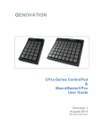
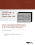
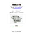
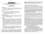
17741 MITCHELL NORTH, IRVINE CALIFORNIA 92614 USA PHONE: (949) 833-3355 FAX: (949) 833-0322 INTERNET: http://www.genovation.com Email: [email protected] Controlpad™ 681 Fully Programmable 35-Key Serial or USB Virtual Serial Keypad Controlpad 681 Controlpad 681-U RS232C Standard Serial USB Virtual Serial Device User Manual Revision 4.0 For Windows 95/98, NT 4.0, 2000, ME, XP Copyright © 2005, Genovation Inc. Manual Last Updated May 1, 2005 Table of Contents 1. o o 2. o o 3. 4. o o o o o o o 5. Technical Specifications. Controlpad 681 (RS232). Controlpad 681-U (USB). Hardware Installation. Controlpad 681 (RS232). Factory Default Settings. Controlpad 681-U (USB). Factory Default Settings. Software Installation. Basic Programming and Set-Up. Running the MacroMaster681 Application. Setting up the Serial COM port. Keypad Properties. Programming Keys. Saving your Set-Up. Downloading to the Keypad. Testing the Controlpad 681. Advanced Programming Functions. o o o o o o o o Two-Level Applications. 6. 7. 8. Creating and Printing Keycap Legends. Inserting Delays into your Key Definition. Assigning a Level Select Key. Level Shift Key. Level Toggle Key. HOST Application In-Line Commands. Turn LED ON/OFF. Set Keyboard Typematic Delay/Rate. Contacting Technical Support. Product Warranty Agreement. TECHNICAL SPECIFICATIONS (Controlpad 681) Number of keys 35 Key Type / Life Full-Travel, Cherry, Gold Contact (50,000,000+ operations) Interface Port Standard RS232C Compatible (Half-Duplex) Power 5vdc Regulated Wall AC Adaptor (Included) Temperature 0-60C (32-140F) Programmability 35 keys, two levels. Program Method Memory Keycap Labels Equipment Provided 111 bytes per key per level. Easy to use Windows based graphical interface to modify the serial port communication settings, and key codes. Once programmed, Controlpad 681 will retain its definitions in its internal memory. It will then function on any standard RS232C compatible serial port. No computer memory or TSR’s required. Controlpad 681 indefinitely retains macro definitions even when power is removed. Pre-made templates can be edited using any Windows Wordpad application or Microsoft Word 6.0 and above. • 6-foot RS232C Compatible Cable • DB-9 Female Connector (Serial) • 5vdc Regulated AC Wall Adaptor • Quick Installation Guide • CD-ROM Installation Software TECHNICAL SPECIFICATIONS (Controlpad 681-U) Number of keys 35 Key Type / Life Full-Travel, Cherry, Gold Contact (50,000,000+ operations) Interface Port USB (1.0, 1.1, 2.0) Compatible Port Power Self-Powered from the USB Port. Temperature 0-60C (32-140F) Programmability 35 keys, two levels. Program Method Memory Keycap Labels Equipment Provided 111 bytes per key per level. Easy to use Windows based graphical interface to modify the serial port communication settings, and key codes. Once programmed, Controlpad 681 will retain its definitions in its internal memory. It will then function on any standard USB port. No computer memory or TSR’s required. Controlpad 681 indefinitely retains macro definitions even when power is removed. Pre-made templates can be edited using any Windows Wordpad application or Microsoft Word 6.0 and above. • 6-foot USB Compatible Cable • • Quick Installation Guide CD-ROM Installation Software HARDWARE INSTALLATION (Controlpad 681) The Controlpad 681 is designed to connect to a standard RS232C compatible serial port via a standard DB9 female plug. A 5vdc regulated AC wall adaptor is included to provide power. Default Codes Hardware Reset to Factory Settings • Standard ASCII number values (1=31h) • Unplug power from the keypad • Followed by “ENTER” (0Dh) • Hold down any two keys on the keypad • Example (Key # 35) = (31h + 35h +0Dh) • Plug the power into the keypad • Release the two keys. HARDWARE INSTALLATION (Controlpad 681-U) The Controlpad 681-U is designed to connect to a standard USB compatible port and creates a virtual serial COM port within the Windows Operating system. Default Codes Default Codes • Standard ASCII number values (1=31h) • Unplug power from the keypad • Followed by “ENTER” (0Dh) • Hold down any two keys on the keypad • Example (Key # 35) = (31h + 35h +0Dh) • Plug the power into the keypad • Release the two keys. SOFTWARE INSTALLATION The Controlapd 681 includes a CD-ROM which contains the drivers and applications for all Genovation products. • • • • • • Insert the CD-ROM. The CD-ROM will auto-start to an opening menu. Click on the “Controlpad 681“. Select the “Controlpad 681“ from the list. You can print the manuals, or select to install the MacroMaster681. Follow the prompts as they pop-up. Re-boot your PC when finished. Upgrading? You can use this same software to perform a new installation or an upgrade. Need special or custom installation assistance? If you are working in a network environment and need to deploy the driver software or your custom definition files across the network, contact our technical support if you need assistance. (The contact information is located on page 7 of this manual). Check our web site www.genovation.com for upgrades. The sub-folder "Macro Files" is the directory location where ControlPad Definitions are saved and retrieved. The "Help" sub-folder holds the program's internally used help files. The "Keycap Files" sub-folder is the directory location where Keycap Label files are saved and retrieved. When programming keycap labels in Microsoft Word, find the provided template files in this directory. BASIC PROGRAMMING METHOD To create and download custom macro definitions for the CONTROLPAD 681, follows these instructions. Click on • • • • • Start Programs Genovation CONTROLPAD 681 MacroMaster681 Program. Basic Macro Programming: One level, standard key characters, factory default parameters. • Select the key to program in the CONTROLPAD 681 key area on the screen (Point & Left-Click to select a key) • Select the key to insert into a macro by pointing to it on the 104 keyboard graphic and left-click the mouse to select it, or by typing the "green" colored keys on your standard keyboard. Repeat this step for additional keys to insert into the macro. • You can give each key macro a name which may make it easier to remember what the keys function is. Simply Click on the edit box called "Name" and type in the name of the key macro. For example: Cut, Copy, or Paste. You can create a name for a key macro on level one and two if you use two levels. • Repeat steps 1 and 2 to program other CONTROLPAD 681 keys. Macromaster681.exe looks like this. Setting up the Serial COM port • Click on “Set Port“ button to locate the Controlpad 681. • If you already know the serial port COM number, then click on the “Set COM port manually“ selection, then choose the COM port you are using and click “OK“ to save. If you do not know the serial COM port, then click on the “Search for Controlpad automatically“ selection, then the OK button to connect. When finished, any Controlpad 681 devices found will be listed in the dropdown box. Choose the port you want and click “OK“ to save. Keypad Properties Click on the “Properties“ Button to open the “Keypad Properties“ window. This is where you can modify the basic serial port settings and functionality of the Controlpad 681. Click the “Apply“ button to save any changes made. LED Mode: This property sets how the LED will operate. • • • LED OFF- Disables LED controls Level Indicator - LED shows “ON” when Level 2 is “ACTIVE” and “OFF” when level 1 is “ACTIVE” LED Under Host Control - Allows the Host application program to control the LED state. Character Pacing: This property controls the time delay in between each ASCII byte sent. If you program a key with more than one byte of data (String), then the Controlpad 681 will send the first byte and delay by the time set in this property. For Example: Let’s assume that a key is programmed to send a string of ASCII bytes “HELLO”. The Controlpad 681 will send the following H delay E delay L delay L delay O delay Download Delay: This property is similar to the above “Character Pacing” property. This property controls the time delayed between each byte sent to the Controlpad 681 during a download. This value may need to adjusted if errors occur during the download process. Command Prefix: This property controls Command prefix byte which is sent by the host application to the Controlpad 681 as part of an in-line command to control various keypad functions like clearing the LCD display, changing the LCD cursor type, moving the LCD cursor position, activating the internal beeper or alarm, etc. If this property is changed, then you must perform a hardware factory reset prior each download. This is because the download application uses the default prefix. A full list of the in-line commands are provided in the Controlpad 681 Hardware Manual. RS232 Settings :This property controls the serial COM port communications settings such as baud rate, data bits, stop bits, parity and protocol. If this property is changed, then you must perform a hardware factory reset prior each download. This is because the download application uses the default RS232 settings of (9600,8,n,1). Keypad Flow Control: This property activates the Xon/Xoff flow control property and allows you to change the ASCII value used to command the keypad in and out of Xon/Xoff mode. Basically, the host application can command the Controlpad 681 to Xoff or stop transmitting. The keypad will then buffer any keys pressed until the host sends the Xon command. It will then send the entire contents of the buffer to the host application. Key Rollover: This property sets how many keys can be pressed at the same time. The default is two. This means that after one key is pressed and held down another key can be detected. If you select the one-key rollover option then when one key is held down, no other keys can be detected. PROGRAMMING KEYS Enter the ASCII codes that you want to record into the selected key location. There are three ways to enter ASCII codes. • Use your mouse to click on the keys you want to record. Use the keyboard graphic which is located on the bottom of the MacroMaster681 Program window. This will automatically insert each ASCII code selected into the black colored grid. • Use your standard keyboard, which is already attached to your PC, to type in the ASCII codes. Only the green colored keys are available from your keyboard directly because they represent ASCII text characters. The other codes will have to be entered using your mouse. You may also enter the actual ASCII code manually by typing the ASCII code as a decimal or hexadecimal value and then click the INSERT button. SAVE YOUR SET-UP Save your ASCII code definitions to a file. This file will contain all the keypad properties and the ASCII table needed to download to the keypad. • Click on the "Save as" button. Type in a filename and click on "Save". Download to the Keypad Click on the "Download" button. This will download the macro definitions from the filename you last saved. Testing the Set-Up Test your work. • Click on the "Test" Button. A window will open and you can test your Mini-Terminal 9xx set-up here. • Select the serial COM port that the Mini-Terminal is plugged into. • Change the serial port settings if needed. (Baud rate etc) Click on the “Open” button. (Opens the selected COM port) • Any ASCII data received by the test program will be displayed in the “Serial Data-IN (Receive) “ text window. • To send a message to the LCD, simply type in a text message in the “String” window and click on the “Send“ button. • You may also send command strings by entering the ASCII code (in Decimal) into either the “Start Packet“ or “End Packet“. If nothing is entered, then these are ignored. • For example: Enter the decimal number “64“ into the “1“ Start Packet byte and enter the decimal number “67“ into the “2“ Start Packet byte. (This will clear the LCD display.) • Now type “Hello World !!!” into the “String” window. (This will Clear the LCD and then send the message every time you click the “Send” button). Now, Enter the decimal number “64” into the “1” End Packet byte and enter the decimal number “66” into the “2” End Packet byte and finally enter the decimal value “50” into the “3” End Packet Byte. This will command the keypad beeper to activate for 50 milliseconds. Any time the “Send” key is clicked, the test program will send the “Start” Packet (Clear LCD), then the text message, then activate the beeper for 50 milliseconds. Advanced Programming Two Level Programming: To program a key's second level, click on the Level 2 tab located near the top of the graphic keyboard then proceed to program key codes the same as for level 1. Delay between characters: To insert a delay/pause into a key definition,. just set the slider located above the numpad on the keyboard graphic to the delay you want and click on the button "Insert Delay". Any delay value can be inserted between 4 millisecond and 500 milliseconds. 500 milliseconds is equal to ?second. For really long delays, several delay entries can be successively programmed. This function will stop the transmitting of key data for the specified time period. Level Select Key: To access the second level of key definitions, a key on the Controlpad 681 a key must be chosen as a level select key. There are two types of level select keys, level shift and level toggle. To select a key to be a level control key, right-click on it and the click on either level shift or level toggle. • Level Shift: A level shift key when pressed and held along with another key will output the level 2 definition of the other key. Once the level shift key is released, level 1 macros will again be selected when you press keys. NOTE: To use the Level Shift key, a minimum of 2 key rollover must be programmed under Keypad Properties since the Shift control key must be pressed and held with another key to access that key's second level macro (the default rollover is 1). • Level Toggle: Pressing and releasing the level toggle key will lock the Controlpad 681 into level 2 until the level toggle key is pressed and released again • Both Shift and Toggle can each be assigned a key on the Controlpad 681. Auto Repeat Enable: Each key on the Controlpad 681 can be individually selected to autorepeat. When programming a key, the checkbox below the level tabs on the graphic keyboard labeled "This macro can auto-repeat" will determine if the Controlpad 681 key selected will auto-repeat. If this box is not checked, the key will not auto-repeat. HOST Application In-Line Commands: The Controlpad 681 allows the HOST side application to send In-Line commands directly to control specific functions. ‘L’ - 4Ch - Turn LED on/off Description: Allows a Host side application program to turn the LED “ON” and “OFF” by sending a Only bit 0 of the parameter byte is used, so any odd value turns LED on, while any even value turns LED off. Example: Turn the LED on. Prefix Command Param Type ASCII: @ L ^A Dec: 64 76 1 Hex: 40h 4Ch 01h Example: Turn the LED off. Prefix Command Param Type ASCII: @ L ^B Dec: 64 76 2 Hex: 40h 4Ch 02h ‘T’ - 54h - Set Keyboard Typematic Delay/Rate Description: Sets the keyboard repeat values for initial-delay and repeat-rate.The initial-delay is the amount of time from when a key is held before the key begins to auto-repeat.The repeatrate is the frequency of characters once the auto-repeat takes effect.Note that these values are subject to other operating conditions such as the RS232 character pacing. The format of the supplied parameter is identical to the delay/repeat byte the IBM PC uses internally for its keyboard: 0 Delayb6 Delayb5 Rate Rate Rate Rate Rate b4 b3 b2 b1 b0 The base delay value is 0.25 seconds. If b5 is set, then an additional 0.25 seconds is added to the delay value.If b6 is set, then an additional 0.5 seconds is added to the delay value.Therefore the delay can be from 0.5 seconds to 1.00 seconds. The repeat-rate (actually a period) is fastest at 00000b and is approximately 30 characters/second.The slowest rate is 11111b and is equivalent to approximately 2 characters per second. The default power-on value for this parameter is ‘l’ (lowercase L) which is (6Ch).This provides a delay of 1 second and a repeat rate of 10 characters/second. Example:1.00 second delay and approximately 2cps repeat rate. Prefix Command Typematic Type Delay/Rate ASCII: @ T ~ Dec: 64 84 126 Hex: 40h 54h 7Eh Creating and Printing Keycap Legends Allows the user to create and print custom keycap legends using a pre-designed template for Microsoft Word Click on the”Keycap Labels” button to open a Microsoft Word Template. You may then add text and graphics to create keycap legends. TECHNICAL SUPPORT If you require technical support or if you wish to make suggestions about the product, don’t hesitate to contact us. We can be reached Monday though Friday from 7:30 AM to 11:00 AM and from 11:30 AM to 4:00 PM Pacific Time. If the customer support lines are busy or after hours, leave a message or send a FAX or E-MAIL and a representative will respond typically within 24 hours. VOICE NUMBER: FAX NUMBER: EMAIL: WEB: (949) 833-3355 ext. 120 (949) 833-0322 [email protected] http://www.genovation.com WARRANTY REPAIR SERVICE AND LICENSE Genovation, Incorporated ("Genovation") warrants this product to be in good working order and free of defects in materials and workmanship under normal use for a period of one year from the date of purchase. Any implied warranties, including warranties of merchantability and fitness for a particular purpose, are limited in duration to a period of thirty (30) days from date of purchase. Any abuse including opening the case will void the warranty. Your sole remedy and Genovation's entire liability for this product will be repair or replacement as provided for above, or at Genovation's option, the refund of your purchase price. A RETURN MATERIAL AUTHORIZATION (RMA) number is absolutely required before returning a product. Any shipment received without an RMA will be returned unopened. Please contact Customer Service for instructions before returning any product. Genovation makes this software available and licenses its use to you world wide for use only with a single Genovation ControlPadd. FCC CERTIFICATION The Serial Micropad has been certified to comply with FCC, EC, TUV and other test standards. See label on the product for confirmation. FCC CERTIFICATION REQUIRED STATEMENT WARNING: This equipment has been certified to comply with the limits for a Class B Computing Device, pursuant to Subpart J of Part 15 of the FCC rules. Only peripherals (computer, computer input/output devices, terminals, printers, etc.) certified to comply with the Class B limits may be attached to this device. Operation with non-certified peripherals is likely to result in interference to radio and TV reception. NOTE: This equipment generates and uses radio frequency energy and if not installed and used properly, that is, in strict accordance with the manufacturer's instructions, may cause interference to radio and television reception. It has been type tested and found to comply with the limits for Class B computing devices in accordance with the specifications in Subpart J of part 15 of the FCC Rules, which are designed to provide reasonable protection against such interference in a particular installation. If this equipment does cause interference to radio or television reception, which can be determined by turning the equipment off or on, the user is encouraged to try to correct the interference by one or more of the following measures: * Reorient the receiving antennas * Relocate the computer with respect to the receiver * Move the computer away from the receiver * Plug the computer and receiver into different circuits If necessary, the user should consult the dealer or an experienced radio/television technician for additional suggestions. The user may find the following booklet prepared by the Federal Communications Commission helpful: How to identify and Resolve Radio-TV Interference Problems". This booklet is available from the U.S. Government Printing Office, Washington, DC 20402. (Stock #004-000-00345-4).