1
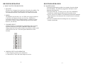
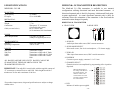
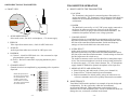
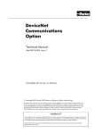
IMPORTANT SAFETY INSTRUCTION
For your protection, please read and observe all safety instructions before operating this receiver
and keep this sheet and any additional instructions for future reference.
INSTALLATION
OBSERVE WARNINGS: All warnings in the operating instructions should be carefully
followed.
WATER AND MOISTURE: Do not use or install this equipment near water. Severe electrical
shock, personal injury or damage to the equipment may result.
Operations Manual
HEAT: Do not install the equipment near heat sources such as radiators, stoves, heat registers
and other appliances that produce heat.
CARE & USE
POWER SOURCE: Connect the equipment to a power source only of the type described on the
operating instructions or as marked on the equipment.
MiniLink® 5.8 GHz System
ATTACHMENTS: Use only MicroTek recommended attachments.
WHEN NOT IN USE: Unplug the power if the equipment is left unattended or unused for long
periods of time or during lightning storms
REPLACEMENT PARTS: When replacement parts are required, use only replacement parts
specified by the manufacturer or that have the same characteristics as the original part.
Unauthorized substitutions may result in fire, electrical shock or other hazards and will void the
warranty.
FCC NOTICE
This equipment has been tested and found to comply with the limits of a Class B
device, pursuant to PART 15C of the FCC Rules. These limits are designed to
provide reasonable protection against harmful interference.
This equipment generates, uses and can radiate radio frequency energy, and, if
not installed and used in accordance with the instructions, may cause
harmful interference to radio communications. However, there is no guarantee
that interference will not occur in a particular installation. If this equipment does
cause harmful interference to radio or television reception, which can be determined
by turning the equipment off and on, the user is encouraged to try to correct
the interference by one or more of the following measures:
• Reorient or relocate the receiving antenna.
• Increase the separation between the equipment and receiver.
• Connect the equipment into an outlet on a circuit different from that to which
the receiver is connected.
• Consult your dealer or an experienced radio/RF technician for help.
Microtek Electronics, Inc.
P.O. Box 3464, San Clemente, CA 92673
Information Hotline 888-36-MICRO
www.microtekelectronics.com
Any changes or modifications not expressly approved by the manufacturer could void
the user’s authority to operate the equipment.
INDEX
QUICK START GUIDE
SECTION
PAGE #
QUICK START GUIDE
RECEIVER DESCRIPTION -----------------------------FRONT PANEL ----------------------------------------------REAR PANEL ------------------------------------------------REMOTE CONTROL ---------------------------------------WIRING DIAGRAM ----------------------------------------RECEIVER OPERATION --------------------------------HOW TO PROGRAM NEW CHANNELS --------------REMOTE CONTROL KEY OPERATION --------------RECEIVER SPECIFICATIONS ------------------------LNB DESCRIPTION ---------------------------------------HOW TO SETUP THE LNB -------------------------------MAINTENANCE --------------------------------------------LNB SPECIFICATIONS ----------------------------------TRANSMITTER DESCRIPTION -----------------------FCC NOTICE -------------------------------------------------FRONT VIEW ------------------------------------------------REAR VIEW --------------------------------------------------TRANSMITTER OPERATION -------------------------HOW TO SETUP THE TRANSMITTER ----------------MAINTENANCE --------------------------------------------TRANSMITTER SPECIFICATIONS ------------------TROUBLE SHOOTING ------------------------------------
2
3-6
3
4
5
6
7–9
7
8-9
10
11
11
11
12
13
13
13
13
14
14
14
15
16
-1-
TRANSMITTER SETUP
1. Remove Transmitter from box, select frequency and audio mode.
(Factory set to channel 1)
2. Mount the transmitter at the desired transmit location. Position
transmitter for desired polarity using rear label arrow as a reference,
transmitter and receiver polarity must match one another.
3. Connect power, audio and video inputs to transmitter.
LNB SETUP
1. Remove LNB from box and mount at the desired receive location in line
of site with the transmitter. Position LNB for desired polarity using rear
label arrow as a reference, transmitter and LNB polarity must match one
another. The LNB is weatherproof.
2. Connect cable to the LNB. (Use only RG 6 coaxial cable with the
supplied waterproof “F” connectors to connect Receiver and LNB.
Cable length should be a minimum of 10 feet and a maximum of 200
feet.)
Note: If a dish is used with the system, assemble the dish and mount the LNB in the dish
as described in the dish installation instructions. Position the dish with LNB and connect
the cable to the LNB as described above.
RECEIVER SETUP
1. Remove Receiver from box and position it at the desired receive
location.
2. Connect cable from the LNB to the “RF IN” on the back panel of the
receiver.
3. Connect the audio and video outputs to a monitor.
4. Connect the power using the included 12 VDC power supply.
Trouble Shooting: If video does not appear on the screen or you are having other
operational difficulties, please visit the trouble shooting section on page 15 of the
operations manual or contact MicroTek toll free at (888) 366-4276 for technical
assistance.
-2-
MINILINK® 5.8 RECEIVER DESCRIIPTION
C. BOTTOM VIEW
A. FRONT VIEW
1
2
1
1. LED INDICATOR
Indicates power is on when illuminated
B. REAR VIEW
1. CHANNEL SELECT DIPSWITCH
Dip switch for selection channels 1 – 10. (Receiver and transmitter
channels must match)
1
2
3
4
5
1. POWER INPUT
12VDC 440 mA. Power supply included.
2. RF INPUT
“F” connector, connection to LNB via RG6 coaxial cable.
3. AUDIO OUTPUT
Mono audio output to video monitor or VCR, use either right or left
channel
4. VIDEO OUT
Supply filtered, clamped video output to video monitor or VCR.
5. VIDEO OUT
Supply filtered, clamped video output to video monitor or VCR.
2. CHANNEL SELECT LABEL
Shows dip switch settings for channels 1 – 10.
D. WIRING DIAGRAM
IMPORTANT: Use only RG 6 coaxial cable
with the supplied waterproof “F” connectors to
connect Receiver and LNB. Cable length should
be a minimum of 10 feet and a maximum of 100
feet. Longer cable runs require line amplifier,
contact MicroTek for information.
12VDC
Power
Supply
DVR/Monitor Audio In
DVR/Monitor Video In
Extra Video Out
-3-
-4-
LNB
RECEIVER OPERATION
RECEIVER OPERATION
A. HOW TO SETUP THE RECEIVER
B. MAINTENANCE
1. LOCATON
The Receiver is designed to be placed on a flat surface for stability. The
Receiver is not weatherproof and should be placed indoors or in an
environmental enclosure if used outdoors or in a harsh environment.
2. POWER
The MiniLink is powered by a 10-14.5 VDC power supply connected
to the Power In connector on the rear of the case. The Receiver
incorporates internal reverse voltage protection. The Receiver itself
uses 220 mA of power and the LNB, which gets its power from the
Receiver, uses 220 mA.
Your Microtek Electronics product is an example of superior design
and craftsmanship. The following suggestions will help to ensure
maximum operational life.
• Keep the product dry. If it does get wet, wipe it dry immediately.
Liquids may contain minerals than corrode electronic circuits.
• Use the system only within the environmental specifications indicated.
High temperatures can shorten the life of electronic devices and melt
plastic parts.
• Excessive mechanical shock can damage the case, connectors or
internal circuit board.
3. CHANNEL SELECT
Channel selection is accomplished by programming of the 4-position
dipswitch located at the rear panel. Match the dipswitches to the
setting on the label for the desired channel (Any numbers visible on the
switch itself are not used. The white squares indicate the switch
location).
4. ORDER OF SETUP AND OPERATION
• Select Frequency (Factory set to channel 10)
• Connect Power, Video and Audio outputs to receiver.
-5-
-6-
RECEIVER SPECIFICATIONS
MINILINK® 5.8 LNB DESCRIPTION
MINILINK® 5.8 RECEIVER
A. FRONT VIEW
RF SECTION
Input Frequency Range
Frequency Control
Input Impedance
IF Bandwidth
Static Threshold
Image Rejection
971 MHz to 1088 MHz
Synthesized PLL
75 Ohms
15 MHz
6 dB (Typical)
40 dB (Typical)
VIDEO SECTION
Format
DE-Emphasis
Frequency Response (3 dB)
Output Level
Output Impedance
NTSC/PAL
CCIR 405-1
50 Hz to 3.8 MHz
1.0 V P-P +/- 5%
75 Ohms
AUDIO SECTION
Sub-carrier Frequency
Bandwidth
Frequency Response (3 dB)
Output Impedance
6.0 MHz
150 KHz
50 Hz to 18 KHz
10 K Ohms (unbalanced)
MECHANICAL
Size
Weight
4.69”w x 4.38”d x 1.44”h
16 oz
POWER
Power Requirements
10-14.5 VDC @ 440 mA
Internally fused, reverse
voltage protected
(LNB power supplied by Receiver)
ENVIRONMENTAL
Humidity
Operating Temperature
95% non-condensing
-20F to +180F case temperature
*For product improvement, design and specifications are subject to change
without notice.
-7-
B. REAR VIEW
1
1. RF OUTPUT
Coaxial cable output to the receiver (971 – 1088 MHz). Power supplied to
the LNB from receiver through this cable at 9-16 VDC.
IMPORTANT: Use only RG 6 coaxial cable with the supplied waterproof
“F” connectors to connect Receiver and LNB. Cable lengths should be a
minimum of 10 feet and a maximum of 100 feet. Longer cable runs
require line amplifier, contact MicroTek for information.
LNB OPERATION
A. HOW TO SETUP THE LNB
LOCATION
The LNB is designed to be mounted against a flat surface for support and
stability. The LNB may also be mounted with an adjustable mount for
positioning. The LNB is designed for environmental applications and is
suitable for use outdoors where it may encounter rain, snow, high wind, etc.
B. MAINTENANCE
Your MicroTek Electronics product is an example of superior design and
craftsmanship. Use the system only within the environmental
specifications indicated. High temperatures can shorten the life of
electronic devices and melt plastic parts. Excessive mechanical shock can
damage the case, connectors or internal circuit board.
-8-
LNB SPECIFICATIONS
MINILINK® 5.8 TRANSMITTER DESCRIPTION
MINILINK® 5.8 LNB
The MiniLink 5.8 GHz transmitter is available in two transmit
configurations utilizing directional and omni directional antennas. A
directional transmit path is ideal for frequency isolation and fixed pointto-point applications. An omni directional transmit path is ideal for
situations where the orientation of the transmitter is not fixed and the
transmit location changes frequently.
RF SECTION
LO Frequency
IF Output
MECHANICAL
Dimensions
Weight
Connections
Cable (see note below)
POWER
Power Requirements
4770 MHz
971 to 1088 MHz
2.75” x 2.75” x 1.5”
7.7 oz
Waterproof “F” connectors
(2 included with system)
RG 6 Coaxial Cable
(10 ft minimum, 100 ft maximum)
DIRECTIONAL TRANSMITTER
A. FRONT VIEW
B. REAR VIEW
6
9-16 VDC @ 220 mA
(LNB power supplied by Receiver)
ENVIRONMENTAL
Humidity
Operating Temperature
RANGES
1000 Feet
2500 Feet
1 Mile
4 Mile
5
100% non-condensing
-20F to +180F
Transmitter to LNB
Transmitter to LNB with 6” Patch
Transmitter to LNB with 18” Dish
Transmitter to LNB with 1 Meter
Dish
ALL RANGES ASSUME LINE OF SITE. RANGES CANNOT BE
GUARANTEED IF THERE ARE OBSTACLES IN THE
TRANSMIT/RECEIVE PATH.
IMPORTANT: Use only RG 6 coaxial cable with the supplied waterproof
“F” connectors to connect Receiver and LNB. Cable lengths should be a
minimum of 10 feet and a maximum of 100 feet.
*For product improvement, design and specifications are subject to change
without notice.
-9-
4 3 2
1
1. AUDIO IN
Audio input from audio source, BNC coaxial connection.
2. AUDIO MODE SELECT
Select audio source, line level or microphone, +5 V electret supply.
3. VIDEO IN
Video input from camera source, BNC coaxial connection.
4. POWER IN
Connect to power supply, connector 2.1 x 5.5 mm.
5. CHANNEL SELECT
Channel selection is accomplished by programming of the 4-position
dipswitch.
Match the dipswitches to
the setting on the label for
the desired channel. Any
numbers visible on the
switch itself are not used.
The white squares indicate
the switch location.
6. LED
Indicates if unit has power applied.
- 10 -
OMNI-DIRECTIONAL TRANSMITTER
TRANSMITTER OPERATION
A. FRONT VIEW
A. HOW TO SETUP THE TRANSMITTER
1
2
3
4a
4b
5
1. AUDIO MODE SELECT
Select audio source, line level or microphone, +5 V electret supply
2. VIDEO IN
Video input from camera source, 4 inch 24 AWG white wire.
3. AUDIO IN
Audio input from audio source,4 inch 24 AWG green wire.
4. POWER IN
(a) Ground – 4 inch 24 AWG black wire. Also connected to 4 pin
plug attached to power supply.
(b) Power – Red wire connected to 4 pin plug attached to power
supply
5. CHANNEL SELECT
Channel selection is accomplished by programming of the 4-position
dipswitch.
Match the dipswitches to
the setting on the label for
the desired channel. Any
numbers visible on the
switch itself are not used.
The white squares indicate
the switch location.
1. LOCATON
The Transmitter is designed to be mounted against a flat surface for
support and stability. The Transmitter is not weatherproof and should be
mounted in an environmental enclosure if used outdoors or in a harsh
environment.
2. POWER
The MiniLink is powered by a 6-14.5 VDC power supply connected to
the Power In connector on the rear of the case of the directional
transmitter or the 4 pin plug of the omni-directional transmitter. The
transmitter incorporates internal reverse voltage protection.
3. CHANNEL SELECT
Channel selection is accomplished by programming of the 4-position
dipswitch located at the rear panel of the directional transmitter and on
the front of the omni-directional transmitter. Switch and frequency
settings are listed on the label below the switch access.
4. AUDIO SELECT
Audio mode selection is enabled by programming the 2-position
dipswitch located at the rear panel of the directional transmitter and on
the front of the omni-directional transmitter. Switch settings are listed on
the label adjacent to the switch access.
The Audio In connector can be used for either line or microphone input
levels. If an electret microphone is used, the second switch position can
be selected to supply +5 V to the electret element. The +5V microphone
supply should be disabled for dynamic microphone or line input uses.
5. ORDER OF SETUP AND OPERATION
• Select Frequency and Audio mode. (Factory set to channel 10)
• Connect Power, Video and Audio inputs to transmitter.
• Position transmitter for desired polarity using rear label arrow as a
reference, transmitter and receiver polarity must match one another.
B. MAINTENANCE
Your MicroTek Electronics product is an example of superior design and
craftsmanship. Use the system only within the environmental
specifications indicated. High temperatures can shorten the life of
electronic devices and melt plastic parts. Excessive mechanical shock can
damage the case, connectors or internal circuit board.
- 11 -
- 12 -
TRANSMITTER SPECIFICATIONS
TROUBLE SHOOTING
MINILINK® 5.8 TRANSMITTER
PROBLEM
RF SECTION
Power Output
Transmitting Frequency
No picture or sound, no
indicator lights
50 mV/Meter @ 3 Meters
5741, 5754, 5767, 5780, 5793, 5806,
5819, 5832, 5845, 5858 MHz
JRR-PS37-4
FCC ID (Directional Transmitter)
FCC ID (Omni-directional Transmitter) JRR-PHL4-13
VIDEO SECTION
Color Format
Pre-emphasis
Input Level
NTSC
CCIR 405-1, 525 lines
1.0 V P-P @ 75 Ohms
AUDIO SECTION
Input Level
Line Level 0.5 V P-P @ 10 K Ohms
Microphone Level 50 mV P-P
Powered Input +5 V @ 25mA
MECHANICAL - DIRECTIONAL
Dimensions
Weight
Connections
BNC
2.75” x 2.75” x 1.5”
9.04 oz
Power supply, video BNC, Audio
MECHANICAL – OMNI DIRECTIONAL
Dimensions
1.5” x 2.4” x 0.43” (w/out antenna)
Weight
1.8 oz
Connections
Power, video, audio and ground on
4 pin plug. (Video, audio and ground
connections are 4 inch 24 AWG leads)
POWER
Power Requirements
ENVIRONMENTAL
Humidity
Operating Temperature
No Picture or sound but
indicator lights are on
6-14.5 VDC @ 100 mA
Reverse voltage protected
Picture has sparkles or
picture is grainy
Video fine-tuning will
not adjust channel
properly. Excessive
black or white sparkles
on all channels
Audio Sounds distorted
or hearing noise, pops
and clicks
SOLUTION
1. NO POWER – make certain that all equipment
is plugged into the proper power source.
2. Check power supply to make sure it is
outputting the required voltage.
1. LNB is not pointed at the transmitter. Verify the
transmitter is aimed at the LNB properly. You
should have clear, wide-open line of site
between the transmitter and LNB
2. Poor cable connections. Check all cable
connections and connectors.
3. Defective LNB. Replace defective part.
1. Receiver antenna is not aligned with the
transmitter. Readjust antenna to match polarity.
2. Video channel is improperly set.
3. Excessive signal loss between LNB and
receiver. Install line amplifier.
4. LNB is defective. Check all coaxial
connections.
5. Poor connections. Check all coaxial
connections.
6. Water in coaxial cable connections. Check all
connections, dry out if necessary and make sure
all connectors used outdoors are suitable for
environmental conditions.
1. LNB off frequency. Have a qualified service
technician check LNB
1. Select audio is not tuned to proper sub-carrier.
Check correct audio frequency.
95% non-condensing
-20F to +180F
RANGES
SEE LNB SPECIFICATIONS ON PAGE 9 FOR SPECIFIC RANGES.
*For product improvement, design and specifications are subject to change
without notice.
- 13 -
- 14 -
MICROTEK LIMITED WARRANTY
Microtek Electronics extends the following LIMITED WARRANTY to the
original owner/purchaser of this product:
1) If, within two years after date of initial sale, this product, or any part or
portion thereof, shall prove upon examination by MICROTEK, to be
defective in material or workmanship, MICROTEK will repair or replace
such part or portion at MICROTEK’s option. The warranty period on the
repaired or replaced part or portion of this product shall be limited to the
unexpired term of the original warranty. The buyer shall be responsible
for all shipping and transportation of the product to MICROTEK for any
performance under this warranty.
2) Conditions and Exceptions:
a) Any accident to this product, any misuse or abuse, alternation, use in
modified form, or any attempt to repair this product shall void this
warranty. These conditions to the warranty include, but are not
limited to, incorrect power connections, physical damage due to
mechanical shock, exposure to moisture, and circuit modification.
b) SHOULD THIS PRODUCT PROVE DEFECTIVE FOLLOWING
PURCHASE, THE BUYER, NOT THE MANUFACTURER,
DISTRIBUTOR, OR RETAILER, ASSUMES THE ENTIRE COST
OF ALL SERVICING OR REPAIR, EXCEPT AS OTHERWISE
PROVIDED BY THE TERMS OF THIS WARRANTY.
c) FOR BREACH OF ANY WRITTEN OR IMPLIED WARRANTY
ON THIS PRODUCT, THE BUYER IS LIMITED TO THE
FOLLOWING DAMAGES. (1) THE COST OF LABOR TO
REPAIR OR REPLACE DEFECTIVE PARTS OR PORTIONS OF
THIS PRODUCT, AND (2) THE COST OF THE REPAIRED OR
REPLACE PARTS OR PORTIONS OF THIS PRODUCT.
d) NO OTHER EXPRESSED OR IMPLIED WARRANTIES HAVE
BEEN MADE OR WILL BE MADE ON BEHALF OF MICROTEK
WITH RESPECT TO THE SALE, REPAIR, INSTALLATION,
OPERATION, OR REPLACEMENT OR THIS PRODUCT.
MICROTEK DISCLAIMS ANY IMPLIED WARRANTY OF
MERCHANTABILITY OF THIS PRODUCT OR ITS FITNESS
FOR ANY PURPOSE, AND THE BUYER AGREES THAT THIS
PRODUCT IS SOLD “AS IS” AND THAT THE ENTIRE RISK OF
QUALITY AND PERFORMANCE OF THIS PRODUCT IS WITH
THE BUYER, EXCEPT AS OTHERWISE PROVIDED BY THE
TERMS OF THIS WARRANTY.
e) Some states/jurisdictions do not allow exclusions or limitations of
incidental or consequential damages, or limitations on how long an
implied warranty lasts, so the above exclusions or limitations may not
apply to you.
3) Contact your dealer regarding return authorization for out of warranty
repairs and any further product information.
Microtek Electronics, Inc.
P.O. Box 3464, San Clemente, CA 92673
Information Hotline 888-36-MICRO
www.microtekelectronics.com