
1
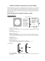
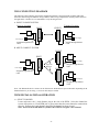
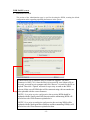
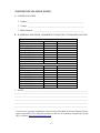
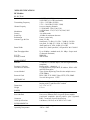
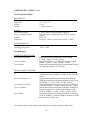
OPERATIONS MANUAL
MiniLink® Wireless Ethernet Systems
MicroTek Electronics, Inc.
25691 Atlantic Ocean Drive, Suite B-3; Lake Forest, CA 92630
Information Hotline 888-36-MICRO
www.microtekelectronics.com
IMPORTANT SAFETY INSTRUCTION
For your protection, please read and observe all safety instructions before operating this system and keep this sheet and
any additional instructions for future reference.
INSTALLATION & USE
OBSERVE WARNINGS: All warnings in the operating instructions should be carefully followed. Do not make any
modifications to the WEM, PIM, or any other MicroTek electronic device, as the unit will no longer comply with FCC
regulations and therefore cancel its warranty.
WATER AND MOISTURE: The Wireless Ethernet Modules used in this system are weatherproof provided they are
installed in accordance to the mounting details listed on page 7 (or included dish manual for the 30-mile systems).
However, further protection or housing is suggested for harsh environments, as moisture damage voids its warranty (as
described on page 22). The Power Injection Modules used in this system are NOT weatherproof. None of the modules
in this system are waterproof and should never be submerged. Severe electrical shock, personal injury or damage to the
equipment may result.
POWER SOURCE: Connect the equipment to a power source only of the type described on the operating instructions or
as marked on the equipment. Excessive or insufficient amperage or voltage can cause extended trouble-shooting or even
damage that could negate its warranty. The power supplies’ cable should not be modified/extended due to the ability to
use up to 300 feet of power over Ethernet (see pg 7, part D). In addition, Ethernet cable running from the PIM to the
WEM should be kept separated from high-voltage cables and/or transformers.
ATTACHMENTS: Use only MicroTek supplied or recommended Power Injection Modules, Power Supplies, CAT5
Cables and weather seals and plugs.
WHEN NOT IN USE: Unplug the power if the equipment is left unattended or unused for long periods of time or
during lightning storms.
REPLACEMENT PARTS: When replacement parts are required, use only replacement parts specified by MicroTek
Electronics, Inc. Unauthorized substitutions may result in damage to the system and will void the warranty.
FCC-Required Information Federal Communications Commission
Radio Frequency Interference Statement for Class A Digital Devices
This equipment has been tested and found to comply with the limits for a Class A digital device, pursuant to Part 15 of
the FCC Rules. These limits are designed to provide reasonable protection against harmful interference when the
equipment is operated in a commercial environment. This equipment generates, uses, and can radiate radio frequency
energy and, if not installed and used in accordance with the instruction manual, may cause harmful interference to radio
frequencies. Operation of this equipment in a residential area is likely to cause harmful interference in which case the
user will be required to correct the interference at his own expense.
This equipment is designed to be professionally installed exclusively for fixed point-to-point applications. These products
must be controlled due to radio frequency power output levels emitted with special consideration given to antenna
placement as it relates to human exposure. Compliance is the responsibility of the installer and user.
Radio Frequency Interface Statement
This equipment has been tested and found to comply with the limits for an intentional radiator, pursuant to Part 15,
Subpart C of the FCC Rules. This equipment generates, uses, and can radiate radio frequency energy. If not installed and
used in accordance with the instructions, it may cause interference to radio communications. The limits are designed to
provide reasonable protection against such interference in a residential situation. However, there is no guarantee that
interference will not occur in a particular installation. If this equipment does cause interference to radio or television
reception, which can be determined by turning the equipment on and off, the user is encouraged to try to correct the
interference by one or more of the following measures:
•
Reorient or relocate the receiving antenna of the affected radio or television.
•
Increase the separation between the equipment and the affected receiver.
•
Connect the equipment and the affected receiver to power outlets on separate circuits.
•
Consult the dealer or an experienced radio/TV technician for help.
Shielded cables must be used with this unit to ensure compliance with Class A FCC limits. Changes or modifications to
this unit not expressly approved by the party responsible for compliance could void the users authority to operate the
equipment. Changes or modifications not expressly approved by MicroTek could void the users authority to operate the
equipment.
-(i)-
FCC Output Power Restrictions
The FCC does not require licensing to implement this device. License-free operation in the industrial, scientific, and medical
band is documented in FCC Rules Part 15.247. It is the responsibility of the individuals designing and implementing the
radio system to assure compliance with any pertinent FCC Rules and Regulations. This device must be professionally
installed.
Exposure to Radio Frequency Fields
The Minilink 5.8WES is designed to operate at 5.8 GHz with up to 50 Watts EIRP maximum transmit power. This level of
RF energy is above the Maximum Permissible Exposure (MPE) levels specified in FCC OET65:97-01. The following
precautions must be taken during installation of this equipment:
•
The installed antenna must not be located in a manner that allows exposure of the general population to the direct
beam path of the antenna at a distance less than 1 Meter. Installation on towers, masts, or rooftops not accessible
to the general population is recommended; or
•
Mount the antenna in a manner that prevents any personnel from entering the area within 1 Meter from the front of
the antenna.
•
It is recommended that the installer place radio frequency hazard warnings signs on the barrier that prevents
access to the antenna.
•
During installation and alignment of the antenna, do not stand in front of the antenna assembly.
•
During installation and alignment of the antenna, do not handle or touch the front of the antenna.
These simple precautions must be taken to prevent general population and installation personnel from exposure to RF
energy in excess of specified MPE levels.
Industry Canada Restrictions
This device is in compliance with the applicable sections of the Industry Canada RSS-210 Spectrum Management and
Telecommunications Radio Standard Specification that governs Low Power License-Exempt Radiocommunication Devices.
Specifically, the output EIRP of this device relative to antenna gain is factory set to ensure compliance with section
6.2.2(q1)(iv)(g).
In addition, it is noted for all users that high power radars are allocated as primary users (meaning they have priority) of the
5250-5350 MHz and 5650-5850 MHz frequency bands and these radars could cause interference and/or damage to LELAN
devices such as are covered by this manual.
Environmental Limitations of FCC License-Free Wireless Devices
MicroTek products are engineered to the highest standards and designed to work in a variety of wireless applications and
environments. A wireless environment includes not only a particular site in which the product is installed but also the
installation itself and any extra materials that might be necessary to complete the wireless project. Due to the fact that
environments and installations differ from site to site, MicroTek cannot control the variables required to ensure an ideal
environment. Therefore, it is not possible to guarantee a successful application based on a drawing, application note, quote
or other type of material that MicroTek may provide. Should a quote, drawing, etc. be made available, it is based on the
performance of the WES product in an ideal environment with clear line-of-sight, absence of 5 GHz interference and/or
frequency multi-path reflection. Therefore, MicroTek cannot be held responsible should the products not operate as desired
or should additional products be required to complete a project. In addition, should a particular environment restrict the
usage of the MiniLink WES in any way, MicroTek offers a thirty (30) day return policy from date of original shipment (see
page 3).
- ( ii ) -
INDEX
SECTION
PAGE #
IMPORTANT SAFETY INSTRUCTIONS, FCC NOTICE ---------------- ( i )
RADIO FREQUENCY EXPOSURE, INDUSTRY CANADA ------------- ( ii )
QUICK START GUIDE ----------------------------------------------------------- 2
PRE-INSTALLATION REMINDER, RETURN POLICY ----------------- 3
WEM DESCRIPTION ------------------------------------------------------------- 4
FRONT, REAR & SIDE VIEWS -------------------------------------------------- 4 - 5
PIM DESCRIPTION --------------------------------------------------------------- 5
TOP, RIGHT & LEFT SIDE VIEWS ---------------------------------------------- 5
WES CONNECTION DIAGRAM ----------------------------------------------- 6
WEM INSTALLATION & OPERATION ------------------------------------- 6 - 8
SELECT CHANNEL & POLARITY SELECT ---------------------------------- 6
MOUNT WEM & CONFIGURE CABLE ---------------------------------------- 7
CONNECT WEM & ESTABLISH LINK ---------------------------------------- 8
ADVANCED OPERATION ------------------------------------------------------ 8 - 15
WEB BROWSER INTERFACE --------------------------------------------------- 8
LOGIN & INFORMAITON ---------------------------------------------------------- 9 – 11
STATIONS/APs ----------------------------------------------------------------------- 12
WIRELESS & SECURITY ----------------------------------------------------------- 13
SECURITY ---------------------------------------------------------------------------- 14
ADMINISTRATION ----------------------------------------------------------------- 15 – 16
SYSTEM INSTALLAION NOTES ------------------------------------------------ 17
WEM SPECIFICATIONS -------------------------------------------------------- 18 - 19
TROUBLE SHOOTING ----------------------------------------------------------- 20
FAQ------------------------------------------------------------------------------------- 21
WARRANTY ------------------------------------------------------------------------- 22
COVERED PRODUCTS
PART #
ML WAP
ML WAPOM
ML WSUOM
ML WSU
ML WSUP
ML WSUDI
ML WEM
ML WEMP
ML WEM-30
DESCRIPTION
MiniLink 5.3 & 5.8 GHz Wireless Host / Access Point - Directional
MiniLink 5.3 & 5.8 GHz Wireless Host / Access Point - Omni-directional
MiniLink 5.3 & 5.8 GHz Wireless Client / Subscriber Unit - Omni
MiniLink 5.3 & 5.8 GHz Wireless Client / Subscriber Unit - Standard
MiniLink 5.3 & 5.8 GHz Wireless Client / Subscriber Unit - Patch
MiniLink 5.3 & 5.8 GHz Wireless Client / Subscriber Unit - Dish
MiniLink 5.3 & 5.8 GHz Wireless Ethernet Module
MiniLink 5.3 & 5.8 GHz Wireless Ethernet Module w/ 6” patch antenna
MiniLink 5.8 GHz Wireless Ethernet Module - 30 mile system
*In this manual, WEM refers to all Point-to-Point, Host/Access Point and
Client/Subscriber Unit devices as described in the covered products table above.
-1-
QUICK START GUIDE
MicroTek Electronics, Inc. recommends that all equipment be bench tested
before being installed onsite. This test will ensure the equipment is
functioning properly.
WIRELESS ETHERNET MODULE (WEM) SETUP
1. Remove the WEMs from box, select frequency via the rotary switch at the side of the unit.
(Factory set to channel 1 – channels 0, 1 & 2 are the same frequency) The channels of each
set of WEMs must be matched for the WEMs to communicate with each other. For multiconnect devices, each Client SU WEM must be set to the same channel as the Host AP WEM
it will be connected to. If connecting more than one Client SU WEM to a Host AP WEM,
please see the advanced operation section of this manual for setup.
2. Mount the first WEM at the desired location.
3. Point the WEM as accurately as possible to the point where the second matched WEM or
Host AP WEM will be mounted.
4. Remove the Power Injection Modules (PIMs) from the box and determine where they will be
located for each WEM. The total distance between a WEM and connected Ethernet device
cannot exceed 300 feet (100 meters). The PIMs can be located anywhere along the 300 feet
of CAT5 cable. Connect standard CAT5 straight through cable to the “Ethernet Out” port on
each PIM to its corresponding WEM. The “Ethernet In” port on each PIM should be
connected to its respective Ethernet device using a standard CAT5 straight through cable. A
crossover cable may be needed depending on your Ethernet device.
5. Connect the included power supplies to the “Power In” port on the PIMs and plug the
transformers into a standard 110VAC outlet. If the Ethernet devices on each end are
connected, powered up and aimed correctly, the “Link Activity”, “Power” and “Signal
Level” LEDs will illuminate. If the Ethernet device is not connected the “Power” LED and
“Signal Level” LEDs only will illuminate. If the “Signal Level” LED is flashing, the WEMs
are communicating but at slower rate than 20 Mbps. Reposition the modules to achieve max
signal strength. For multi-connect applications, the Each Client WEM will show a solid
green light when connected to a Host AP WEM. A flashing green LED on the “Multi-point
Host AP” will indicate the number of Client Subscriber Units to which it is connected.
Note: If a dish is used with the system, assemble the dish and mount the WEM in the dish as
described in the dish installation instructions. Position the dish with WEM and connect the
CAT5 cable as described above.
Trouble Shooting: If the signal level indicator is not fully lit, video does not appear on the
screen or you are having other operational difficulties, please visit the trouble shooting
section on page 20 of the operations manual or contact MicroTek toll free at (888) 366-4276
for technical assistance.
-2-
PRE-INSTALLATION REMINDERS
The information on the Quick Start Guide is intended for ease of use and application, the following
reminders will help to ensure your satisfaction with MicroTek products and service.
1. Read through this manual before bench testing and installation
2. Perform a bench test incorporating all components of the application
3. Install your MiniLink Wireless Ethernet System
4. Toll-free technical assistance is available Monday through Friday (8-5pm PST) at 888-3664276
MICROTEK ELECTRONICS RETURN POLICY
MicroTek Electronics products come with a 2-year limited warranty, (see the last page for warranty
information) unless otherwise specified. In addition to the 2-year warranty, products may be returned
within thirty (30) days of shipment provided the products are in like new condition and in the original
packaging. Contact your MicroTek Electronics dealer or distributor to obtain an authorization to
return the merchandise for credit.
Return authorizations for repair can be sent directly to Microtek Electronics with a valid RA number.
Call MicroTek Electronics to obtain an RA number for repair.
ETHERNET STANDARD WIRING NOTE
The Ethernet standard straight-through cable configurations used must be configured to one
of the two Ethernet standards (568-A or 568-B) in order for the WES system to operate
correctly. Any deviation from one of the two standard configurations can lead to undesired
activity so make sure your cables are configured as shown in one of the drawings below:
568-A
568-B
•
•
Drawing shown with gold pins facing up and RJ-45 clip in rear (clip not shown)
If 568-B is configured on end of a CAT5 cable and 568-A is configured on the other
end, that configuration would be a standard crossover cable.
-3-
MINILINK WIRELESS ETHERNET SYSTEM (WES)
The MiniLink WES is a plug and play CAT5/Ethernet cable replacement device. It operates in the
5.3 and 5.8 GHz U-NII bands on 8 non-overlapping channels. The WES system enables a wide
variety of IP cameras, DVRs, encoders/decoders and web servers to be used across wireless line-ofsight links in ranges of 500 feet to 30 miles. The system operates independent of any network it
may be connected to.
MINILINK WIRELESS ETHERNET MODULE (WEM)
WEM DESCRIPTION
A. FRONT VIEW
B. REAR VIEW
NOTE: Horizontal
Ethernet Port is not
available. Mount
WEM so that
Vertical Ethernet
Port is at bottom and
use weatherproof
caps and plugs as
described on pg 7.
5
1 23 4
1. LINK ACTIVITY LED
Indicates that a solid Ethernet link is connected between powered Ethernet device & WEM.
2. POWER LED
Indicates the WEM has power.
3. SIGNAL LEVEL LED
Indicates the signal strength level between WEMs. On the Host AP WEM, indicates the
number of Client SU WEMs connected. Note: This is not an indication of available throughput.
4. ETHERNET PORT
Standard RJ-45 connector.
5. CHANNEL SELECT
Rotary switch for channel selection, factory set to Channel 0.
Note: Channel positions 0, 1 and 2 are all the same frequency- next available frequency is Channel 3.
C. SIDE VIEW
1
3
2
1.
MOUNTING HOLES
(2) ¼ - 20 mounting holes – Attach the outdoor mounting equipment as described in detail on page 7
of this manual.
-4-
C. SIDE VIEW (cont’d)
2.
ETHERNET PORT
Standard RJ-45 connector.
3. ROTARY CHANNEL SELECT SWITCH
Shows switch settings for channels 0 – 9.
*Note: Channels 0, 1 and 2 are the same frequency. If two or more systems are in use and
either channel 0, 1 or 2 are used on the first system, the following systems must be set to
channel 3 or higher. If the second system is not set to channel 3 or higher, the two systems
could interfere with one another. When changing channels, power to each WEM must be
cycled for the WEM to recognize and operate on the new channel.
POWER INJECTION MODULE (PIM)
Note: The Power Injector Modules are not weatherproof units and must be protected from moisture.
PIM DESCRIPTION
A. TOP VIEW
2
1
3
1. ETHERNET IN – Connect to Ethernet device
2. POWER IN – 12-20 VDC Center Positive
3. ETHERNET OUT – Connect to WEM
B. RIGHT SIDE VIEW
1. POWER LED – Lit when power is on
2. ETHERNET OUT – Connect to WEM
3. POWER IN – Connect to Power Supply
1
2
3
C. LEFT SIDE VIEW
1. ETHERNET IN – Connect to Ethernet device
1
-5-
WES CONNECTION DIAGRAM
The following wiring schemes represent the configurations that have been tested and verified by MicroTek
Electronics based on typical Ethernet wiring solutions. Other wiring configurations could be possible based on
the application. A bench test is recommended to verify the designs below.
A. POINT-TO-POINT SYSTEM
Transmit Location
Receive Location
HOST
CLIENT
PIM
PIM
Power Supply
Power Supply
Straight-through Ethernet
Cable
Straight-through Ethernet
Cable
B. MULTI-CONNECT SYSTEM
CLIENT
PIM
HOST
PIM
Power Supply
Up to 90
Degrees
Straight-through Ethernet
Cable
CLIENT
Power Supply
Straight-through Ethernet
Cable
PIM
Power Supply
Straight-through Ethernet
Cable
Note: The Ethernet/IP device connects to the “Ethernet In” RJ45 Ethernet port on the PIM. Depending on the
Ethernet/IP device you are using, a crossover cable may be needed.
WEM INSTALLATION & OPERATION
A. SELECT CHANNEL
Locate and remove the ½ inch diameter plug at the side of the WEM. Select the channel the
system will operate on. Each WEM pair or group must share the same channel to communicate
properly. Replace the ½ inch diameter plug after the channel has been selected.
Note: Power to the WEM must be cycled for the WEM to recognize a new channel.
-6-
WEM INSTALLATION & OPERATION (cont’d)
B. MOUNT DIRECTIONAL WEM
Mount the WEM with the
included wall/pole mount
B-1
bracket and hardware. Connect
the mounting block with ball
adjustment to mounting bracket
with the ¼ - 20 button head
screw. Connect the WEM to the
mounting block using the ¼-20
mounting holes in the WEM.
Position the WEM and point
it in the desired direction
Tighten the jam nut against
¼ - 20
Button Head
the bottom of the WEM case
Screw - 1x
to lock it in position.
B-2
Directional WEM
U-Bolts w/
Clamps - 2x
¼ - 20 Lock
Washer – 5x
¼ - 20 Nut – 4x
C. MOUNT OMNI-DIRECTIONAL WEM
Mount the WEM with the
included wall/pole mount
bracket and hardware. Connect
the WEM to the wall/pole mount
bracket using the ¼-20 button head
Omni -directional
¼ - 20 Lock
Washer – 2x
¼ - 20 button
Head Screw – 2x
screws and lock washers.
¼ - 20 Lock
Washer – 2x
U-Bolts w/
Clamps - 2x
¼ - 20 Nut – 4x
D. CONFIGURE CABLE
Determine the length of CAT5 cable that will be needed and where the PIM will be located. The
total cable length from the WEM to the Ethernet device cannot exceed 300 feet, however, the
PIM can be located anywhere along the 300 feet of cable. The PIM and power supply are not
weather proof and must be placed indoors or in an environmental enclosure. On the WEM end,
feed the CAT5 cable through the supplied weatherproof connector. Slide the supplied black
cable jacket over the cable. Crimp an RJ45 CAT5 connector on the end of the cable and
configure as a straight-through cable.
-7-
WEM INSTALLATION & OPERATION (cont’d)
E. CONNECT WEM
Connect the cable to the WEM. Slide the cable jacket up to the base of the connector. Slide the
weatherproof connector over the cable jacket and screw it into the WEM and tighten. Tighten
the clamping nut until the CAT5 cable is sealed in the connector. Check the WEM positioning
and make sure the Power and Link Activity LEDs are on. The Link Activity indicator, amber
LED, will only illuminate if an Ethernet source device is connected and powered up, and the red
LED will verify power is being sent over the Ethernet cable. See drawing B-2 (page 7).
F. ESTABLISH LINK
Follow above steps, A through E, for both ends of the link to be established. After both ends
have been installed and powered up, the green Signal Level LED will illuminate. A solid green
LED indicates the WEMs are communicating at a maximum throughput standard rate of up to 20
Mbps. If the green LED is flashing, the WEMs are communicating at a level less than 20 Mbps.
If this occurs, realign the WEMs to achieve the maximum throughput.
NOTE: Maximum throughput requires a line-of-sight transmission path between the WEMs and
no 5 GHz interference. In some cases, depending on the physical and RF environment, a useable
throughput rate may not be possible. Contact MicroTek for more information – 888-366-4276
or [email protected].
ADVANCED OPERATION
WEB BROWSER INTERFACE
Each WEM has a web browser interface to access the advanced setup functions. If changing
advanced settings, be sure to connect and power the WEMs individually. To access this interface,
connect the WEM to the Ethernet port on a computer, launch the web browser and type in the
default IP address. The configuration of the computer used to access the WEM may need to be
changed depending on its IP settings. The IP address of the computer should be changed to
192.168.1.xxx. The xxx setting can be any address 2 – 254 excluding 200 and 201 or any other IP
address(s) you wish to use for a WEM (or Encoder/Decoder solution if applicable). The Subnet
mask should be 255.255.255.0. If you have any questions or concerns about changing these
settings, please contact your network administrator. The default user name for each WEM is admin
and the password is admin.
WARNING: IF YOU CHANGE THE USER NAME AND/OR PASSWORD, YOU WILL NEED TO KEEP A
RECORD OF YOUR CHANGES IN A SAFE PLACE. IF THE USER NAME AND/OR PASSWORD IS
FORGOTTEN OR MISPLACED, THE WEM MUST BE RETURNED TO MICROTEK TO BE RESET.
A. POINT-TO-POINT SYSTEMS
A point-to-point system consists of a Host AP WEM and a Client SU WEM. The default IP
address for the Host AP WEM is 192.168.1.200. The default IP address for each Client SU
WEM is 192.168.1.201. To access the either WEM unit, type in the default IP address of the unit
you wish to connect to.
B. MULTI-CONNECT SYSTEMS
The default IP addresses for each Host AP WEM is 192.168.1.200. To access the Host AP
WEM, type in the default IP address 192.168.1.200. The default IP address for each Client SU
WEM is 192.168.1.201. If more than one Client SU WEM will be connected to a Host AP
WEM, the IP address of each additional Client SU WEM will need to be changed in the
-8-
B. MULTI-CONNECT SYSTEMS (cont’d)
Administration Page (Section E below) manually. If you ordered a complete system with
multiple Client SU WEMs, they have been pre-configured with IP addresses as follows:
Client SU WEM
Unit 1
Unit 2
Unit 3
Unit 4
Unit 5
Serial Number
00511*
00512*
00553*
00624*
00714*
IP Address
192.168.1.201
192.168.1.202
192.168.1.203
192.168.1.204
192.168.1.205
(*Actual serial numbers will be different)
Note: The lowest serial number of the Client SU WEM you received is pre-configured with IP address
192.168.1.201. The next higher sequential serial number of the Client SU WEMs you received has IP
address 192.168.1.202, etc. If you ordered an additional Client SU WEM separate from your original
order, the default address is 192.168.1.201. The IP address in this additional unit will need to be changed
manually to the next available IP address before installation. An IP address-numbering table is included
in the SYSTEM INSTALLATION NOTES section of this manual on page 17 for your convenience in
keeping track of IP address changes and other notes about your specific application. The green LED on a
multi-connect Host AP will flash to indicate the number of Client SU units connected to it.
WEB PAGES
A. LOGIN
The default user name for each WEM is admin and the password is admin.
Note: The user name and password are case sensitive.
-9-
WEB PAGES (cont’d)
B. INFORMATION
1. POINT-TO-POINT HOST AP WEM
The information page provides the details of how the Single-Point Host WEM is configured.
Access Point Name:
Bridge Name:
MAC Address:
Firmware Version:
Current Channel:
Turbo Mode:
Rotary Switch Pos:
25.5dBi Jumper:
17.7dBi Jumper:
Security:
IP address:
In most cases, the Access Point, or Host, is the receiving unit
The subscriber or client unit is the transmitting device
Individual Ethernet device identification code
The latest firmware version is 6.4.0P (7.01)
Refer to “Rotary Switch Position” for actual frequency channel
0= default (off), 1 or 2= on, both units must be on channel 3,6 or 8 to turn turbo mode on
Indicates what channel the software has determined that has been enabled
“On” for: MLWES-30. Client “on” for: MLWES-D6 or MLWSU-DI
“On” for: MLWES-2-4. Client “on” for: MLWSUP
WPA AES 128 bit is standard default, WEP can also be enabled
Shows the IP address of the connected WEM and can be changed as desired
- 10 -
A. INFORMATION (cont’d)
2. MULTI-CONNECT HOST AP WEM
The information page provides the details of how the Multipoint Host WEM is configured.
3. CLIENT SU WEM
The information page provides the details of how the Client WEM is configured.
- 11 -
WEB PAGES (cont’d)
C. STATIONS/APs
1. POINT-TO-POINT AND MULTI-CONNECT HOST AP WEMS
The Stations/Associations page of the Host AP WEM shows the MAC address(s) of the
paired or grouped Client SU WEM(s) the Host AP WEM is connected to. For Point-to-Point
systems, one WEM MAC address will be shown. For Multi-connect systems, the Host AP
WEM will show all of the Client SU WEM MAC addresses currently connected. The page
will also show the mode, rate and RSSI communication information for each connected
Client SU WEM.
RSSI=
Received
Signal
Strength
Indicator.
(Max 70)
Rate= This is
a snapshot of
the rate in
Megabits/sec
of the last
packet as it
went across
the link*
2. CLIENT SU WEM
The APs/Access Points page shows the MAC address(s) and SSID of the Host AP WEM the
Client SU WEM is connected to. It also shows the channel the units are connected on along
with mode, rate and RSSI communication information.
* The Rate as shown on these web page snap-shots do not account for roughly 60% of over-head.
- 12 -
WEB PAGES (cont’d)
D. WIRELESS
The wireless page is used for enabling Super mode. The Super mode combines adjacent
channels to provide up to 50+ Mbps of throughput. The channels available in Super mode are:
3, 6 and 8 only. If another channel is selected, Super mode will not be enabled. To enable Super
mode, click the arrow in the drop down box and select “Super A without Turbo” (30+ Mbps) or
Super A with Static Turbo” (50 Mbps). Each WEM in your system will need to have this feature
enabled independently.
E. SECURITY
1. WPA CONFIGURATION
WPA is the highest grade of encryption available in this system and is enabled at the factory
as the default. WPA2, AES and password are the default selections. After updating the
settings as desired, click save to update the WEM. Please note that paired or grouped WEMs
must have the same settings to operate correctly.
NOTE: Client SU
WEMs do not have the
option of leaving the
PSK blank or a WPA
Group Key Update
Interval selection.
- 13 -
D. SECURITY (cont’d)
2. WEP CONFIGURATION
The security page is used for enabling WEP encryption and setting the parameters for WEP
encryption. Click the “Enable WEP” check box to enable (The WPA configuration will be
automatically disabled). After this box is checked, the Default WEP key is available, as are:
Authentication, WEP key lengths and WEP Key 1-4. After updating the settings as desired,
click save to update the WEM. Please note that paired or grouped WEMs must have the same
settings to operate correctly.
- 14 -
WEB PAGES (cont’d)
F. ADMINISTRATION
This section of the Administration page is used for rebooting the WEM, resetting the default
configuration and/or upgrading/uploading the firmware in the system.
Contact MicroTek to obtain the files for a firmware upgrade. The latest
firmware is 6.04P (7.01). Once the file(s) is/are received, save it/them a file to
be easily accessed in your computer and click “Browse” to search for the file to
upload. Then click “Upload” and wait for up to sixty seconds as the WEM
reboots. Make sure all WEMs that will be communicating with one another are
also uploaded with the correct firmware.
NOTE 1: In a point-to-point configuration, the receiving WEM should be
updated with the Single-point Host firmware and the transmitting WEM will
need to have the Client firmware uploaded to it.
NOTE 2: In a point-to-multipoint configuration, the receiving WEM will be
updated with the Multi-point Host firmware and the transmitting WEM(s) will
need to have the Client firmware uploaded to them.
- 15 -
E. ADMINISTRATION (cont’d)
This section of the Administration page is used for selecting the device name, changing IP
settings and changing the user name and password needed to access the system.
NOTE:
The Device name on the
Admin page of a HOST
AP will be “MicroTek
Host AP”.
The Device name on the
Admin page of a Client
SU will be “MicroTek
Client”.
For Point-to-Point
systems default IP
addresses will be as
follows:
Host AP: 192.168.1.200
Client SU: 192.168.1.201
Please see Advanced
Operation starting on
page 8 for systems
utilizing multiple Client
SU WEMs.
- 16 -
SYSTEM INSTALLATION NOTES
A. SYSTEM LOCATION
1. Address: _________________________________________________________
2. Contact: _________________________________________________________
3. Phone Number: ___________________________________________________
B. IP ADDRESS AND SERIAL NUMBERING TABLE FOR CUSTOM APPLICATIONS
Site #1
Device
WEM #1 (point-to-point applications)
WEM #2 (point-to-point applications)
Host AP WEM
Client SU WEM #1
Client SU WEM #2
Client SU WEM #3
Client SU WEM #4
Client SU WEM #5
Client SU WEM #6
Site #2
Device
WEM #1 (point to point applications)
WEM #2 (point to point applications)
Host AP WEM
Client SU WEM #1
Client SU WEM #2
Client SU WEM #3
Client SU WEM #4
Client SU WEM #5
Client SU WEM #6
Serial Number
IP Address
Serial Number
IP Address
C. NOTES: ______________________________________________________________________
_________________________________________________________________________________
_________________________________________________________________________________
_________________________________________________________________________________
_________________________________________________________________________________
_________________________________________________________________________________
If you have any questions regarding the advanced setup of the MiniLink Wireless Ethernet System,
please contact MicroTek’s Technical Assistance at 888-366-4276 (Monday through Friday 8-5pm
PST) or online at www.microtekelectronics.com
- 17 -
WEM SPECIFICATIONS
RF Modules
RF SECTION
Power Output
Transmitting Frequency
Channel Capacity
Modulation
Latency
Sensitivity
Polarization
Antenna Type & Gain
Beam Width
Data Throughput Rate
FCC ID
Industry Canada
MANAGEMENT
Interface
Frequency Selection
Web Browser Interface
Access Method
Protocols Used
MECHANICAL
Physical
Dimensions
Weight
POWER
Power Requirements
Power Method
1 W EIRP @ 5.3 GHz (maximum)
50 W EIRP @ 5.8 GHz (maximum)
5.250 – 5.350 GHz (U-NII-2)
5.725 – 5.825 GHz (U-NII-3 / ISM)
8 non-overlapping channels
5.3 GHz Band - 5280, 5300, 5320
5.8 GHz Band - 5745, 5765, 5785, 5805, 5825
OFDM
<10 milliseconds
-82 dBm for maximum data rate
Linear, vertical only
Omni, 2.5 dBi
Small patch, 7.5 dBi @ 5.3 GHz , 7.8 dBi @ 5.8 GHz
6x6 patch, 12.2 dBi @ 5.3 GHz, 16.7 dBi @ 5.8 GHz
Small patch in 18” dish, 24 dBi @ 5.8 GHz
Omni-360°, Small patch-90°, 6x6 patch-24° & 18” dish-8°
Up to 20 Mbps - standard mode, 50+ Mbps – Super mode
(3 channels maximum)
JRRWES
4887A-WES
10/100 Base T, half/full duplex, rate auto negotiated (802.3
compliant)
Rotary switch – channels 0 – 9
User ID/Password, Super Mode, IP Address, WPA2 AES
and WEP Encryption
Time division duplexing/Time division multiple access
(TTD/TDMA)
IPV4, UDP, TCP, ICMP, Telnet, HTTP, FTP, SNMP
Network Management HTTP
Environmental, sealed, billet aluminum, powder coated
housing with UV stabilized PVC radome
3.6” x 3.6” x 1.75”
15.2 oz
Connector
Cable Specifications
12 - 20 VDC @ 3 W (Reverse voltage protected)
Power-over-Ethernet (PoE) via power injector module
(“mid-span” compliant – pins 4,5 positive – pins 7,8 ground)
RJ45 – in and out of power injection box
100 Meters (328 Feet) on 24 AWG CAT-5 cable
ENVIRONMENTAL
Humidity
Operating Temperature
95% non-condensing
-20F to +150F
- 18 -
WEM SPECIFICATIONS (cont’d)
Power Injection Module
MECHANICAL
Physical
Dimensions
Weight
Interface
POWER
Power Requirements
Power-over-Ethernet (PoE)
Plastic housing, not weatherproof
2.6” x 2.6” x 1.1”
2.5 oz
2 – RJ45 connectors
Indicator
Connectors
12 VDC 500 mA (wall transformer supplied)
PoE “mid-span” compliant (pins 4,5 positive – pins 7,8
ground)
LED - red
DC Jack 2.5 mm x 5.5 mm center positive, 2 – RJ45
ENVIRONMENTAL
Humidity
Operating Temperature
95% non-condensing
-20F to +150F
System Ranges
POINT-TO-POINT SYSTEMS_______
Up to 2600 & 3900 Feet
Integral directional patch antennas on both WEMs 5.3 GHz – 2600 ft, 5.8 GHz – 3900 ft
Up to 2 & 4 Miles
Integral directional 6 x 6 13-dBi patch antennas on both
WEMs – 5.3GHz – 2 miles, 5.8 GHz – 4 miles
Up to 30 Miles
Integral directional patch antennas on both WEMs mounted
in 25 dBi dish antennas - 5.8 GHz only
MULTI-CONNECT SYSTEMS
Up to 500 & 1000 Feet
Up to 1300 & 2600 Feet
Up to 2600 & 3900 Feet
Up to 1 & 2 Miles
Up to 6 Miles
Integral omni-directional patch antennas on both the Host
AP WEM & Client SU WEM - 5.3 GHz - 500 ft, 5.8 GHz –
1000 ft
Integral omni-directional patch antenna on the Host AP
WEM & integral directional patch antenna(s) on the Client
SU WEM(s) - 5.3 GHz 1300 ft, 5.8 GHz - 2600 ft
Integral directional patch antenna on the Host AP WEM &
Client SU WEM(s) - 5.3 GHz – 2600 ft, 5.8 GHz – 3900 ft
Integral directional patch antenna on the Host AP WEM &
integral directional 6 x 6 13-dBi patch antenna(s) on the
Client SU WEM(s) - 5.3GHz – 1 mile, 5.8 GHz – 2 miles
Integral directional patch antenna on the Host AP WEM &
Client SU WEM(s) – Client SU WEM(s) mounted in 25 dBi
dish antenna(s) 5.8 GHz only
*For product improvement, design and specifications are subject to change without notice.
- 19 -
TROUBLE SHOOTING
PROBLEM
No Link Activity
No Signal Level LED or
Flashing Signal Level
LED
All three solid LEDs but
no picture or picture
drops out after a period
of time
No Green Signal Level
LED (When Using the
MLWES-30 with two
18” Parabolic Dishes)
SUGGESTION
1. NO POWER – make certain both WEMs have power and
the red Power LED is on. Make sure the connected
Ethernet/IP device is powered.
2. Check the configuration of all WEMs. Each pair and/or all
groups of WEMs setup to communicate with each other
must be set to the same channel. If you have changed any
of the advanced settings, make sure the configurations of all
WEMs being used in the system are the same.
3. Make sure the cable run between the WEM and Ethernet
device is no longer than 300 feet.
4. Make sure the cables being used are straight through and all
cable connectors are attached properly.
5. If using an Ethernet hub or fast switch, try a crossover cable
between the hub and the Power Injector Module.
1. Check line-of-sight of the WEMs. Verify the WEMs are
aimed properly. You should have clear, wide-open line of
sight between the WEM modules.
2. Change channels; cycle power.
3. Verify sufficient voltage into each PIM.
Note: The Host AP WEM green signal level LED will flash indicating
the number of Client SU WEMs it is communicating with. This is
normal for this device and should not be confused as lack of signal
strength. The green LED on the Client SU WEM should be solid if
the Client SU is communicating with the Host AP at a full 20Mbps
(50+ Mbps – super mode).
1. Check video at the camera
2. Check wiring into encoders or decoders
3. Try changing channels; cycle power. An uninterruptible
power supply (UPS) may be required and is suggested.
4. Connect one WEM directly into a PC or laptop and verify
that the IP address is accessible. Check the other WEM(s)
the same way, then verify that each IP address is accessible
over the wireless link into a PC/laptop.
5. Verify the connected Ethernet/IP device is configured
correctly.
1. Verify wide-open line-of-sight
2. Re-angle your dish antenna in a downward angle until both
LEDs are solid green.
3. Mount the dishes higher above ground level and/or above
any obstruction.
If you have tried the trouble shooting steps above and the system is still not working correctly, please
contact MicroTek at 888-366-4276, Monday through Friday, between the hours of 8:00AM and
5:00PM Pacific Time. One of our technicians will work with you to rectify the problem over the
phone.
Thank you,
MicroTek Electronics, Inc.
- 20 -
FAQ
Q. Which unit is the transmitter and which is the receiver?
A. WES systems are bi-directional so it is not crucial which of the units is mounted at the receive
location (and vice-versa), however, typically the ‘host’ is the receiver and the ‘client’ is the
transmitter.
Q. How can I tell whether I received the point-to-point WES system versus the point-tomultipoint WES system?
A. There are a few ways to tell which system you have:
1. Each system box is sealed and labeled with the manufacturer’s model number. Point-tomultipoint systems have the following model numbers: MLWES-D, MLWES-OD,
MLWES-D1-2, MLWES-D6 or single units: MLWAP, MLWAPOM, MLWSUOM,
MLWSU, MLWSUP or MLWSUDI
2. The green Signal Level LED on the Access Point (point-to-multipoint systems) will
flash to indicate the number of connected Subscriber Units with which it is
communicating.
3. If the system box is labeled as: MLWES-2500, MLWES-2-4 or MLWES-30, then the
system is a point-to-point system.
Q. Why is one unit labeled as “host” and the other labeled as “client”?
A. The latest revision of the WES firmware enables the WEMs to communicate as one host with
either one only or multiple client, or subscribing, units. A host unit is only able to communicate
with a client and will not communicate wirelessly with another host.
Q. What is the Locator Program?
A. A software program is available that will locate IP addresses of individual WES modules
connected as a system. This program is helpful in case the internal web browser of the WEMs
cannot be accessed.
Q. Is it possible to add cameras (or Ethernet devices) to my existing Wireless Ethernet System?
A. The total amount of data that can be transmitted over the wireless system is 20 Mbps
(Megabits per second) per channel in standard mode (and 50+ Mbps in super mode). As long as
there is bandwidth available in your configuration, more systems can be added to an existing
WES system. Contact MicroTek technical support or sales at 888-366-4276 (Weekdays 8am –
5pm PST) for more information since multiple applications are possible.
Q. What is “super mode”? And, when should super mode be used?
A. Super mode combines bandwidth of adjacent channels to provide 50+ Mbps of throughput.
However, enabling this mode limits the number of channels that are available for transmission (3
channels available: 3, 6 & 8). This mode is ideal for multiple cameras transmitting over one
WES system or to gain bandwidth when transmitting amongst heavy 5 GHz interference.
Q. What does the red dot (sticker) indicate?
A. A red-dot sticker indicates that the 5.3 frequencies are inactive. These units are part
of the MLWES-30 or MLWES-D6 systems only. Channel selections 0-4 are combined
to match channel 5; ensuring that only 5.8 frequencies are used.
- 21 -
WARRANTY INFORMATION
MICROTEK LIMITED WARRANTY
MicroTek Electronics extends the following LIMITED WARRANTY to the
original owner/purchaser of this product:
1) If, within two years after date of initial sale, this product, or any part or
portion thereof, shall prove upon examination by MICROTEK, to be
defective in material or workmanship, MICROTEK will repair or replace
such part or portion at MICROTEK’s option. The warranty period on the
repaired or replaced part or portion of this product shall be limited to the
unexpired term of the original warranty. The buyer shall be responsible
for all shipping and transportation of the product to MICROTEK for any
performance under this warranty.
2) Conditions and Exceptions:
a) Any accident to this product, any misuse or abuse, alternation, use in
modified form, or any attempt to repair this product shall void this
warranty. These conditions to the warranty include, but are not
limited to, incorrect power connections, physical damage due to
mechanical shock, exposure to moisture, and circuit modification.
b) SHOULD THIS PRODUCT PROVE DEFECTIVE FOLLOWING
PURCHASE, THE BUYER, NOT THE MANUFACTURER,
DISTRIBUTOR, OR RETAILER, ASSUMES THE ENTIRE COST
OF ALL SERVICING OR REPAIR, EXCEPT AS OTHERWISE
PROVIDED BY THE TERMS OF THIS WARRANTY.
c) FOR BREACH OF ANY WRITTEN OR IMPLIED WARRANTY
ON THIS PRODUCT, THE BUYER IS LIMITED TO THE
FOLLOWING DAMAGES. (1) THE COST OF LABOR TO
REPAIR OR REPLACE DEFECTIVE PARTS OR PORTIONS OF
THIS PRODUCT, AND (2) THE COST OF THE REPAIRED OR
REPLACE PARTS OR PORTIONS OF THIS PRODUCT.
d) NO OTHER EXPRESSED OR IMPLIED WARRANTIES HAVE
BEEN MADE OR WILL BE MADE ON BEHALF OF MICROTEK
WITH RESPECT TO THE SALE, REPAIR, INSTALLATION,
OPERATION, OR REPLACEMENT OF THIS PRODUCT.
MICROTEK DISCLAIMS ANY IMPLIED WARRANTY OF
MERCHANTABILITY OF THIS PRODUCT OR ITS FITNESS
FOR ANY PURPOSE, AND THE BUYER AGREES THAT THIS
PRODUCT IS SOLD “AS IS” AND THAT THE ENTIRE RISK OF
QUALITY AND PERFORMANCE OF THIS PRODUCT IS WITH
THE BUYER, EXCEPT AS OTHERWISE PROVIDED BY THE
TERMS OF THIS WARRANTY.
e) Some states/jurisdictions do not allow exclusions or limitations of
incidental or consequential damages, or limitations on how long an
implied warranty lasts, so the above exclusions or limitations may not
apply to you.
3) Contact your dealer regarding return authorization for out of warranty
repairs and any further product information.
MicroTek Electronics, Inc.
25691 Atlantic Ocean Drive, Suite B3, Lake Forest, CA 92630
Information Hotline 888-36-MICRO
www.microtekelectronics.com
- 22 -


![Independent Market Operator MPR User Guide [DRAFT] September](http://vs1.manualzilla.com/store/data/006868987_1-010fe7f81b44bbd7b66576ca8ddb10c5-150x150.png)