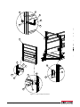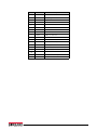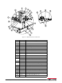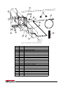
1
Multiple Animal Scale Portable
Installation/Service Manual
PN 132795 Rev E
Contents
1.0
Introduction..................................................................................................................................... 1
1.1 Overview . . . . . . . . . . . . . . . . . . . . . . . . . . . . . . . . . . . . . . . . . . . . . . . . . . . . . . . . . . . . . . . . . . . . . . . . 1
1.2 Safety . . . . . . . . . . . . . . . . . . . . . . . . . . . . . . . . . . . . . . . . . . . . . . . . . . . . . . . . . . . . . . . . . . . . . . . . . . 2
1.2.1
Safety Decals . . . . . . . . . . . . . . . . . . . . . . . . . . . . . . . . . . . . . . . . . . . . . . . . . . . . . . . . . . . . . . . . . . . . . . 3
1.3 Unloading . . . . . . . . . . . . . . . . . . . . . . . . . . . . . . . . . . . . . . . . . . . . . . . . . . . . . . . . . . . . . . . . . . . . . . . 5
1.3.1
1.3.2
1.3.3
Slinging the scale. . . . . . . . . . . . . . . . . . . . . . . . . . . . . . . . . . . . . . . . . . . . . . . . . . . . . . . . . . . . . . . . . . . . 5
Lift the Scale . . . . . . . . . . . . . . . . . . . . . . . . . . . . . . . . . . . . . . . . . . . . . . . . . . . . . . . . . . . . . . . . . . . . . . . 5
Remove Lifting Fixture. . . . . . . . . . . . . . . . . . . . . . . . . . . . . . . . . . . . . . . . . . . . . . . . . . . . . . . . . . . . . . . . 5
1.4 Lifting Assembled Scale. . . . . . . . . . . . . . . . . . . . . . . . . . . . . . . . . . . . . . . . . . . . . . . . . . . . . . . . . . . . . 6
1.5 Package Removal . . . . . . . . . . . . . . . . . . . . . . . . . . . . . . . . . . . . . . . . . . . . . . . . . . . . . . . . . . . . . . . . . 6
2.0
Installation ...................................................................................................................................... 7
2.1 Permanent Installation . . . . . . . . . . . . . . . . . . . . . . . . . . . . . . . . . . . . . . . . . . . . . . . . . . . . . . . . . . . . . 7
2.2 Portable Installation . . . . . . . . . . . . . . . . . . . . . . . . . . . . . . . . . . . . . . . . . . . . . . . . . . . . . . . . . . . . . . . 7
2.3 Switching Modes . . . . . . . . . . . . . . . . . . . . . . . . . . . . . . . . . . . . . . . . . . . . . . . . . . . . . . . . . . . . . . . . . 8
2.3.1
2.3.2
Convert to Weigh Mode . . . . . . . . . . . . . . . . . . . . . . . . . . . . . . . . . . . . . . . . . . . . . . . . . . . . . . . . . . . . . . 8
Convert to Non-Use Mode . . . . . . . . . . . . . . . . . . . . . . . . . . . . . . . . . . . . . . . . . . . . . . . . . . . . . . . . . . . . 8
2.4 Cage Wall Assembly . . . . . . . . . . . . . . . . . . . . . . . . . . . . . . . . . . . . . . . . . . . . . . . . . . . . . . . . . . . . . . . 9
2.4.1
2.4.2
2.4.3
Apply the silicone bead . . . . . . . . . . . . . . . . . . . . . . . . . . . . . . . . . . . . . . . . . . . . . . . . . . . . . . . . . . . . . . . 9
Install walls . . . . . . . . . . . . . . . . . . . . . . . . . . . . . . . . . . . . . . . . . . . . . . . . . . . . . . . . . . . . . . . . . . . . . . . . 9
Install the Gate . . . . . . . . . . . . . . . . . . . . . . . . . . . . . . . . . . . . . . . . . . . . . . . . . . . . . . . . . . . . . . . . . . . . 10
2.5 Gate and Latch Adjustment Procedure . . . . . . . . . . . . . . . . . . . . . . . . . . . . . . . . . . . . . . . . . . . . . . . .
2.6 T-Belt . . . . . . . . . . . . . . . . . . . . . . . . . . . . . . . . . . . . . . . . . . . . . . . . . . . . . . . . . . . . . . . . . . . . . . . . .
2.7 Optional 920i Weighcenter Mounting . . . . . . . . . . . . . . . . . . . . . . . . . . . . . . . . . . . . . . . . . . . . . . . . . .
2.8 Wiring the Scale. . . . . . . . . . . . . . . . . . . . . . . . . . . . . . . . . . . . . . . . . . . . . . . . . . . . . . . . . . . . . . . . . .
2.9 Load Cell Wiring Diagrams. . . . . . . . . . . . . . . . . . . . . . . . . . . . . . . . . . . . . . . . . . . . . . . . . . . . . . . . . .
2.10 Optional AC/DC Power Supply Adapter Box Kit . . . . . . . . . . . . . . . . . . . . . . . . . . . . . . . . . . . . . . . . .
2.10.1
3.0
4.0
11
11
11
13
14
15
Mounting to Scale. . . . . . . . . . . . . . . . . . . . . . . . . . . . . . . . . . . . . . . . . . . . . . . . . . . . . . . . . . . . . . . . . . 15
Repair Parts .................................................................................................................................. 18
Maintenance ................................................................................................................................. 24
4.1 Maintenance Schedule . . . . . . . . . . . . . . . . . . . . . . . . . . . . . . . . . . . . . . . . . . . . . . . . . . . . . . . . . . . . 24
4.2 Scale Maintenance Procedures . . . . . . . . . . . . . . . . . . . . . . . . . . . . . . . . . . . . . . . . . . . . . . . . . . . . . 24
4.3 Specifications . . . . . . . . . . . . . . . . . . . . . . . . . . . . . . . . . . . . . . . . . . . . . . . . . . . . . . . . . . . . . . . . . . . 25
MAS-P Limited Warranty .......................................................................................................................... 26
Technical training seminars are available through Rice Lake Weighing Systems.
Course descriptions and dates can be viewed at www.ricelake.com/training
or obtained by calling 715-234-9171 and asking for the training department.
© Rice Lake Weighing Systems. All rights reserved. Printed in the United States of America.
Specifications subject to change without notice.
Rice Lake Weighing Systems is an ISO 9001 registered company.
February 10, 2015
Contents
i
Rice Lake continually offers web-based video training on a growing selection
of product-related topics at no cost. Visit www.ricelake.com/webinars.
ii
Multiple Animal Scale Portable - Installation Manual
1.0
Introduction
The Multiple Animal Scale Portable (MAS-P) system is manufactured with top quality components and is
engineered using the latest technology to provide operating features and reliability unmatched for years to come.
Please take the time to read this manual completely through before attempting to use the system. Although the
MAS-P has been designed for easy set up and use, a thorough understanding of this manual will ensure that you
receive the maximum benefit from the system.
If you have any questions or comments please contact Rice Lake Weighing Systems.
1.1
Overview
The MAS-P shown below consists of a sheeted animal cage suspended by four S-type load cells through a cam style
On-Board lift system on top a portable base frame. In transport mode, the scale system is locked down, protecting
the load cells from damage during transport. The scale is raised to the weigh mode using a lever and cam system. A
digital indicator is connected to the scale to display the weight.
The MAS-P can be used on any firm surface up to 7% grade (4-degree slope) and has a low deck height (6'') for
easy step in.
Figure 1-1. MAS-P Animal Scale
Introduction
1
1.2
Safety
Safety Symbol Definitions:
DANGER Indicates an imminently hazardous situation that, if not avoided, will result in death or serious injury.
Indicates a potentially hazardous situation that, if not avoided could result in death or serious injury, and
WARNING includes hazards that are exposed when guards are removed.
CAUTION Indicates a potentially hazardous situation that, if not avoided may result in minor or moderate injury.
Indicates information about procedures that, if not observed, could result in damage to equipment or
Important corruption to and loss of data.
General Safety
Do not operate or work on this equipment unless you have read and understand the instructions and
warnings in this manual. Failure to follow the instructions or heed the warnings could result in injury or
death. Contact any Rice Lake Weighing System dealer for replacement manuals. Proper care is your
responsibility.
WARNING
Failure to heed may result in serious injury or death.
DO NOT allow minors (children) or inexperienced persons to operate this unit.
DO NOT operate without all shields and guards in place.
DO NOT use for purposes other than weighing.
DO NOT place fingers into slots or possible pinch points.
DO NOT place hands, feet or any body part underneath the scale at any time. The scale could be lowered, crushing body
parts.
DO NOT use any load bearing component that is worn beyond 5% of the original dimension.
DO NOT use this product if any of the components are cracked.
DO NOT exceed the rated load limit of the unit.
DO NOT make alterations or modifications to the unit.
DO NOT remove or obscure warning labels.
Keep hands, feet and loose clothing away from moving parts.
Some procedures described in this manual require work inside the indicator enclosure. These procedures are to be performed by qualified service personnel only.
Always be certain when lowering the scale that everyone is clear of the scale and any moving parts.
Use two hands when gripping the lift handle to raise or lower the scale.
Be sure the gates are latched or tied inward before transporting the scale.
Ensure all three hitch lock pins are installed and the suspension stops are in the transport position before moving the
scale.
Important
Animal Safety:
Animal safety is a very serious issue and must be observed when handling any type of animal.
The scale surface may become slippery during use; a build-up of manure on the scale may reduce traction. It is
recommended that you take any necessary precautions to maintain an acceptable level of animal footing.
Calibration:
Do not calibrate this scale with a weight cart having a gross weight in excess of 25% of the total capacity of the scale (3750
lbs or 1,700 kg max for the MAS-P 8X13, 5000lb or 2,268 kg max for MAS-P 8x18). This device is designed to be calibrated
with single block weights spread evenly throughout the floor of the scale. Shift tests should not be done with more than
4,000 lbs or 1,815 kg in a 4’ x 4’ area. Failure to comply with this warning will result in damage to the scale and void the
warranty.
2
Multiple Animal Scale Portable - Installation Manual
1.2.1
Safety Decals
1
3
2
7
6
Note
2
1
4
5
Items 2-4 are on units
equipped with the 920i
Weighcenter only.
8
3 4
5
Both
Sides
6
Both
Sides
7
Both
5
8
1
Side
s
6
Both
Sides
Both
Sides
Figure 1-2. Safety Decal Locations
Item #
Part #
1
2
3
4
5
6
7
8
151908
151904
151906
151907
151909
151910
128266
151902
Description
Read Manual
Caution, Low Clearance (Weighcenter)
Warning, Do Not Open (Weighcenter)
Warning, Do Not Leave Tray Down (Weighcenter)
Caution, Pinch Point
Caution, Always Grip With Two Hands
Do Not Use For Transportation of Goods
Warning, Opens Quickly
Qty
3
1
1
2
14
4
2
2
Table 1-1. Safety Decal Parts List
Introduction
3
1
2
3
See Detail A Below
See Detail A
4 Below
5
4
3
Detail A
3
4
Figure 1-3. Non-Safety Decals
Item #
Part #
1
2
3
4
5
164911
127091
132692
127094
16863
Description
Label, 920i Weighcenter Operation
Label, Basic Operation
Label, Weigh/Transport
Label, Weigh/Transport
Serial Number Label
Table 1-2. Non-Safety Decals Parts List
4
Multiple Animal Scale Portable - Installation Manual
Qty
1
1
2
2
1
1.3
Unloading
Follow instructions below to unload the scale.
1.3.1
Slinging the scale.
MAS-P can be slung with four equal length straps connected from the lifting lugs to a single point in the center.
• Strap length 8 x 13 = 7 ft minimum
• Strap length 8 x 18 = 10 ft minimum
11
T
EE
9F
FEE
T
Figure 1-4. Slinging the Scale
1.3.2
Lift the Scale
1. If stacked, monitor the four corners directly below the lifting fixtures. Each corner has a shipping stub
inserted, these stubs are not bolted in place, ensure they remain with the lower scale.
2. Once the upper scale of the stack is removed the stubs can be discarded.
Shipping Stub
Figure 1-5. Shipping Stub
3. The scale can now be stored as is or placed on a relatively flat location to be assembled.
1.3.3
Remove Lifting Fixture
Lifting
Fixture
Remove the lifting fixture after scale has been placed in position.
1. Remove the nylon locknut from the bolt installed for shipping.
2. Remove the lifting fixture from the bolt.
3. Reinstall the nut, retain the lifting fixture for future moves.
Nylon
Locknut
Figure 1-6. Lifting Fixture
Introduction
5
1.4
Lifting Assembled Scale
Lift the scale only in designated locations (see Figure 1-7). The scale can be lifted by four straps and a crane or
loader. Ensure the scale is in the transport mode (locked down – see Section 2.3 on page 8) when loading and
transporting the scale.
Install lifting fixtures to the four inside
corners, see in Figure 1-6.
Install cable hooks at each lifting
fixture to lift scale.
Figure 1-7. Lift Points
1.5
Package Removal
The indicator is shrink wrapped for transportation. Be careful when removing to avoid damaging the indicator.
Remove indicator, then re-strap the walls if the scale is to be transported while packaged.
6
Multiple Animal Scale Portable - Installation Manual
2.0
Installation
As with any weighing equipment, the accuracy of the scale is dependent on the installation. The following points
must be adhered to when installing the MAS-P Animal Scale.
In all installations, the scale must be level to ensure proper operation. All MAS-P Animal Scales are equipped with
a bubble level (located on top the base frame – see Figure 2-1). Ensure the bubble is fully inside the circle marked
on the top of the level.
2.1
Permanent Installation
Rice Lake Weighing Systems recommends a concrete foundation (piles or piers) for permanent installations. The
foundation must be able to support the gross weight of the scale (scale dead weight plus scale capacity), and the
piles or piers must be situated directly under the load cell stands (see shimming location in Figure 2-1). The
foundation must not be subject to distortion or motion due to frost action. A qualified local professional should be
consulted to recommend the proper size of foundation for the location. Foundation dimensional requirements are
available from the dealer or Rice Lake Weighing Systems. Requirements may vary from one Weights and
Measures jurisdiction to another, please contact the local office.
2.2
Portable Installation
The MAS-P is ideal for use in many locations. Simply load and unload the scale as described in the Section 1.4 on
page 6. Locate the scale in as level a location as possible, and shim (with wood or metal shims) under the load cell
stands to ensure the scale is level as described above. Please contact the local Weights and Measures office
regarding the moving of the scale to ensure the validity of the certification.
Scale Cable
Bubble Level
Figure 2-1. Shim/Load Cell Stand Locations
Installation
7
2.3
Switching Modes
2.3.1 Convert to Weigh Mode
1. Place the scale in as level a location as possible. Ensure there are no obstructions under the deck that would
affect weighing accuracy. Check the bubble level. Use shims or timbers to ensure the scale is as close to
level as possible.
Note The scale will weigh properly on any firm surface up to 7% grade (4-degree slope).
2. Inspect all four corners of the scale. Although the scale will weigh properly up to four degrees off level,
individual corners of the scale should not be allowed to teeter. If any of the corners are not contacting the
ground, place shims directly under the base frame, under the load cell stands, to prevent teetering (see
Figure 2-1) .
3. Plug the indicator into the scale cable. The scale cable runs from the junction box (inside the base frame) to
the indicator (see Figure 2-1).
4. Connect power to the indicator and switch ON.
5. USING BOTH HANDS, raise the platform to enable the scale (see Figure 2-2).
The lift mechanism is an over center cam style lift and lock. If not disturbed, the scale will remain “locked”
WARNING in the up position. Always grip lift handle with two hands when raising and lowering the scale.
Cam levers point toward each other in weigh mode and away from each other in transport. See decals for
Note direction of levers in each mode.
6. The scale is now ready to weigh.
2.3.2
Convert to Transport Mode
When the scale is not in use, the scale should be locked down in transport mode to prevent any accidental overload
of the weigh system.
1. USING BOTH HANDS disengage and lock the scale in transport mode by rotating all four cam levers
counter clockwise into the fully locked position.
The lift mechanism is an over center cam style lift and lock. If not disturbed, the scale will remain “locked”
WARNING in the up position. Always grip lift handle with two hands when raising and lowering the scale.
Cam levers point toward each other in weigh mode and away from each other in transport. See decals for
Note direction of levers in each mode.
2. Turn off indicator. A stand alone indicator should be stored indoors when the scale is not in use. The weigh
center should be closed and latch to prevent damage.
Rotate Cam to raise
scale into weigh
position, see decal.
Figure 2-2. Scale Lift
8
Multiple Animal Scale Portable - Installation Manual
2.4
Cage Wall Assembly
2.4.1
Apply the silicone bead
Before installing the walls, a silicone bead must be added.
1. Clean the upper flange of the floor and the lower wall flange with mineral spirits.
2. Apply a 1/8'' bead of silicone along the upper edge of the floor panel along the entire length as shown in
Figure 2-3.
Wall Insert
Silicone
Figure 2-3. Silicon Bead
2.4.2
Install walls
WARNING Wall installation should be done with two people or an overhead crane.
1. Lift the first wall by using one sling in the center.
Note The wall with the holes for the indicator is mounted on the left side.
2. Stand the wall vertical and place the inserts from the wall into the tubes of the cage floor. The more vertical
the wall the easier assembly will be.
3. Repeat for the opposite wall.
4. Install the top cross members.
5. Insert the 3/4 x 3 1/2'' bolts through the cage wall and inserts on the indicator side of the cage, head of bolt
to the inside.
A come-along from the top of the cross member to bottom of the cage corner post may be required. A ratchet
Note strap is provided in hardware kit.
When both walls are in place, ensure that they are perfectly square. Straps may need to be used to pull for
squareness.
Installation
9
2.4.3
Install the Gate
Note
Install the gate with the hinge bolts on the opposite side of the scale.
Hinge bolts must be assembled with lock washer on the inside of gate and the jam nut on the outside.
Install Spring Pins after
gate is in place.
Spring Pin
Cage Wall
Nylon washer
Hook Bolt
Gate
Jam nut
Nut and washer
Washer
Figure 2-4. Assemble Gate to Scale
1. Install jam nut and lock washer onto the hinge bolts. Screw the nut on about 2”.
2. Insert one hinge bolt into the lower and upper holes of the cage wall with the hook portion pointing
upward.
3. Install nut and washer onto the hinge bolts securing them to the cage wall.
4. Place nylon washer onto the hook portion of the upper and lower hinge bolts and install the gate onto the
hooks.
5. Insert roll pin through the hinge bolts.
6. Repeat steps 2-4 for second gate.
7. Adjust the hinge side gap between the gate and the cage wall to about 3” and snug hinge bolts.
10
Multiple Animal Scale Portable - Installation Manual
2.5
Gate and Latch Adjustment Procedure
Note Assemble gates according to the following criteria:
•
•
•
Hinge Bolts - Assemble with lock washer on inside of gate and jam nut on the outside.
Hinge Side Gap - Approximately 3” between the gate and the corner post.
Gate Latch Pin - Install rubber tubing on the latch pin (Mobile units only).
Adjust gates as follows:
1. Adjust the hinge bolts to align the top of the gate on the latch side with the top of the cage wall.
2. Adjust the hinge bolts so the latch side gap is about 1 1/2”.
3. Install and adjust the latch so the gate latch pin does not rub on the top or bottom of the latch. Adjust the
hinge bolts only if necessary.
4. Ratchet straps can be used diagonally to help square up gates to walls.
2.6
T-Belt
Ensure the T-Belt hold down loops are installed and hooked into the corner posts of the cage.
Hold Down
Loop
Figure 2-5. T-Belt
2.7
Optional 920i Weighcenter Mounting
The MAS-P is NTEP approved only when purchased with 920i Weighcenter. When using other indicators, it
Note must be re-calibrated each time it’s moved.
1. Before installing the bracket, a bead of silicone must be
added. See Figure 2-6.
2. Clean the wall tubes where the bracket will mount and the
space between the holes on the mount bracket with
mineral spirits.
3. Place the mounting bracket onto the cage wall by pressing
the adhesive tightly to the cage.
4. Secure with four bolts.
5. Mount the weighcenter onto the mounting bracket and
route the cable as shown in Figure 2-6.
6. Install the clamps to secure the conduit.
• Mount the upper conduit clamp using the lower left
mounting bracket bolt.
• Secure the lower end of the conduit by drilling a hole
through the cage sheeting and installing the clamp with
the bolt provided.
Silicone
Silicone Detail
Conduit Clamp 9/32Ø
Figure 2-6. Weighcenter Mounting
Installation
11
Battery Box Connections
For use with the optional battery box, PN 153765.
1. Connect the scale cable and secure with a cable tie.
2. Connect the power wires as shown in Figure 2-7.
3. Replace the battery cover.
Fus
e
Red
RT
Black
LT 12V TL BRK GND
Blue
See Figure 2-8 for
more wiring details.
Chassis
Figure 2-7. Weighcenter Battery Connections
12
Multiple Animal Scale Portable - Installation Manual
Black
86
Deep Cycle Battery
Relay 85
Red
30 Amp
Circuit
Breaker
Red
Yellow
Red
20 Amp
+V
Left
Right
7.5 Amp
Black
Blue
Orange
Tail
Brakes
30
87
GND
Female
Connector
Male
Connector
D
Indicator
Connector
A
A
B
C
D
Weigh Center
See Detail Below
Black
Battery Box
Chassis
Ground
Point
Wiring the Scale
Load cell cable
to j-box mounted
in scale frame
2.8
-EXC
+SIG
+EXC
-SIG
B
C
Black
Green
Red
White
A
Scale
B
D
C
Scale/Indicator System Connection Detail
Conn PN
127259
127260
Description
Conn, MS, Male
Complete Kit
Conn, MS, Female
Pins w/ clamp
Used With
127260 or
127261
127259
Cap
PN
Cap
Description
15731 Dust Plug, MS
External THD
15730 Dust Cap, MS
INTL THD
Table 2-1. Weighcenter Connector and Plug Configurations
Figure 2-8. Scale Wiring Diagram
Installation
13
2.9
Note
Load Cell Wiring Diagrams
Load cell wiring shown is effective for all models built after 09/17/2013. Models built prior to this date should
rewire the scale to the updated configuration. For information on rewire download Technical Bulletin PN 159193
from www.ricelake.com.
Load
Cell 1
Load
Cell 2
Add 20 ft of cable to load cell 1 for
18 ft mobile scale.
Note
Load
Cell 2
Cables
Add 10 ft of cable to load cell 1 for
13 ft mobile scale.
Load
Cell 2 & 3
Cables
Load
Cell 1 & 4
Cable
Load
Cell 4
Load
Cell 3
J-Box
PT1
EXP
V1
V2
+SE
-SI
-EX
SHD
Load
Cell 2
SHD
-SI
Multiple Animal Scale Portable - Installation Manual
l#
3
-EX
1
C
CELL3
JP3
+SI
el
S2C
l#
2
el
C
PT3
Lo
ad
JP4
Lo
ad
1
el
C
el
C
PT4
l#
1
l#
4
r
ca
to
M
SHD
Figure 2-9. Load Cell Wiring Diagram
14
+SI
-SI
Lo
ad
+EX
-EX
V4
+SI
LCELL4
oa
d
di
In
-EX
V3
+EX
-SE
1
+SI
JP2
1
-SI
Red
+E
Black
SHD
-E
Green
+S
White
-S
SHD
Shield
GND
-SI
Load
Cell 4
IND
+EX
1
-EX
+SI
PT2
JP1
Trimmers
CELL2
CELL1
Load
Cell 1
1
+EX
+EX
Load
Cell 3
2.10 Optional AC/DC Power Supply Adapter Box Kit
The following are instructions to install the AC/DC Power Supply Adapter Box on a portable animal scale.
Figure 2-10. AC/DC Power Supply Adapter Box Kit
2.10.1 Mounting to Scale
Angle Bracket
Bolts for securing
bracket to frame
Backplate
Extensions
Base Frame
of Scale
Figure 2-11. Mounting Power Box Assembly to Frame
Note The mounting bracket can be positioned anywhere along the frame within the limits of the conduit.
1. Place mounting bracket assembly on the outer beam of the bottom frame on the scale in desired location.
Angle bracket should extend past the front of the beam and backplate extensions should be flush with back
of beam.
2. Tighten bolts to secure to frame. Ensure they are tight enough to resist movement when scale is in use.
When ordering a complete package, the enclosure box will be assembled to the mounting bracket.
Note Skip to Step 4.
3. Mount the enclosure box to the mounting bracket using the bolts and washer supplied.
Installation
15
Mounting Bracket
Bolt and Washer
Enclosure
Scale Frame
Figure 2-12. Mount Enclosure Box
To Weighcenter
Conduit Elbow
Existing Conduit
Elbow and Conduit
to Weighcenter
Power Cord
Load Cell Cable Conduit
Through Frame to J-Box
Figure 2-13. Wiring Diagram
16
Multiple Animal Scale Portable - Installation Manual
Ground (Green)
To J-Box
J-Box to
Weighcenter
-12V (Black)
+12V (Red)
Power Cord
Figure 1. Power Supply Connections
4. Disconnect the homerun cable from the weighcenter (see the weighcenter manual PN 156758) and pull it
out of the conduit and conduit elbow.
5. Insert the conduit elbow into the designated hole in the enclosure. Secure with nut.
6. Pass the weighcenter cable from the inside of the enclosure through the conduit elbow and conduit to the
weighcenter.
7. Reconnect the cable to the weighcenter.
Note
The cable to the weighcenter is part of existing assembly and runs through existing conduit retrofitted to power
supply box.
8. Disconnect the cable from the j-box.
9. Connect conduit elbow to the enclosure at designated hole and secure with nut.
10. Connect the other conduit elbow to the frame near the j-box.
11. Pass the j-box cable through the conduit elbow, supplied conduit and conduit elbow on the frame.
12. Reconnect the j-box cable to the j-box.
13. Connect the j-box cable connector and the Weighcenter cable connector inside enclosure.
14. Secure connectors and excess cable with zip-ties inside the enclosure.
Installation
17
3.0
Repair Parts
See Figure 3-2 for
gate hardware
(item 2).
See Figure 3-3 for lift
mechanism parts.
Figure 3-1. MAS-P Parts Illustration
18
Multiple Animal Scale Portable - Installation Manual
Item No.
1
2
3
Part No.
NS
130931
131782
131992
131993
128280
126775
127234
127236
127235
127235
127053
21939
35170
131855
126787
127271
127081
130022
128169
131708
131946
131708
131947
14697
15179
15097
72083
14646
21939
127007
15147
126819
127740
131885
121129
14633
88956
127561
16133
NS
131374
4
5
6
7
8
9
10
11
12
13
14
15
16
17
18
19
20
21
22
NS
Description
Cage Crossmember
Gate, MAS, see Figure 3-2
Mat Installation Kit - 13' (Includes items 4-7)
Mat Installation Kit - 18' (Includes items 4-7)
Adhesive, Insta-Cure + (13’ Qty 1 / 18’ Qty 2)
Sealant, Silicone II Black (13’ Qty 2 / 18’ Qty 3)
Matting, MAS End Section - 13' (Qty 2)
Matting, MAS End Section - 18' (Qty 2)
Matting, MAS Center - 13' (Qty 1)
Matting, MAS Center - 18' (Qty 3)
Bolt, Carriage 5/16-18
Washer, Plain 5/16 Type A
Nut, Lock 5/16-18NC Hex
Mounting Strip, Rubber
Belting, Scale T Profile (83” width)
Hold Down Loops
Bubble Level Circular
Operator Shield
Screw, Self Drilling 12-24 x 7/8
Cage Wall 13’
Cage Wall 18’ Right
Cage Wall 13’
Cage Wall 18’ Left
Nut, Lock 3/4-10 Hex, Nylon Insert Zinc
Washer, Plain 3/4 Type A
Cap Screw, 3/4-10NCx3-1/2
Bolt Carriage 5/16 x 1/2 Round Head Grade A Zinc
Nut 5/16 Flanged Serrated
Washer, Plain 5/16 Type A
Screw, Cap 1/4-20 x 1/2
Washer, Lock 1/4 Regular
Foam Gasket J-box
Cover Plate Scale Frame/J-box
Mount Plate for JBox
Screw 10-32 x 0.5
Nut, 10-32
JBox
Scale Cable Female MS Conn 132”
Sealant, Silicone Clear, (used on cage walls and optional
weighcenter installation)
Paint, Touchup
Table 3-1. MAS-P Parts List
Repair Parts
19
1
5
2
17
4
3
6
7
8
16
9
13
12
8
10
15
11
14
13
Figure 3-2. Gate Component Details
20
Multiple Animal Scale Portable - Installation Manual
Item No.
Part No.
Description
1
132217
2
110950
Pin, Spring 1/4 x 1 1/4
3
165944
Hinge Bolt
4
15179
Washer, 3/4
5
111074
Nut, 3/4-10NC
6
131782
Gate, MAS
7
131701
Eye Bolt, 5/16-18 x 2 1/2
8
131887
Quick Link 1/4 in
9
131886
Cable, 1/4” OD x 6 ft
10
21939
Washer, 5/16
11
14646
Nut, Lock 5/16-18NC
12
131784
Gate Latch Assembly
15
21938
Washer, 3/8 Lock
14
151559
Cap Screw, 3/8-16NCx
15
151560
Cap Screw, 3/8-16 x 3/4
16
155916
Strike Plate
17
151807
Washer, Plain 3/4in Nylon
18
22072
Nut, 3/8-16 Grade5
Jam Nut, 3/4-10NC
Repair Parts
21
1
2
3
15
19
4
18
5
16
14
13
6
17
12
11
7
10
8
9
Figure 3-3. MAS-P Detail Parts Illustration
Item No.
1
2
3
4
5
6
7
8
9
10
11
12
13
14
15
16
17
18
19
20
NS
NS
22
Part No.
Description
127007
Cap Screw, 1/4-20 x 1/2
127200
Load Cell Cam Stand Cover SS
126926
Pin Spring Slotted 1/4x2-1/4
127163
Load Cell S-Type 10K
128184
Upper Notched Load Cell Pin
127668
Lower Load Cell Retainer
127177
Lower Notched Load Cell Pin
126789
Plug Plastic Round 2”
126788
Plug Plastic Round 1-1/8”
14765
Bolt 1/2-13NC x 4
15167
Lockwasher 1/2
131785
127676
127732
Cam Lever Without Lockdown - Rear Left
Cam Lever with Lockdown - Front Left
Cam Handle Mask
131787
127675
127165
Cam Lever with Lockdown - Right Front
Cam Lever Without Lockdown - Rear Right
Spacer Upper Notched Pin
14656
Nut 3/8 SS
15161
Flat washer 3/8 SS SAE
128626
Scale Damper Assembly w/Bushings
126815
Bushing, Rubber 7/8 OD x 3/8 ID x 1.25 Long
22093
Cap Screw, 3/8-16NCx2 Hex
127562
Scale Cable Female MS Conn 132”
76832
Bolt, 3/4-10NC x 6-1/2 Hex
Multiple Animal Scale Portable - Installation Manual
20
1
22
8
2 3 4
9
5
6
7
21
10
16
11
20
19
17
6
7
18
12
15
14
13
Supplied with
enclosure.
Figure 3-4. AC/DC Power Box Parts Illustration
Item No
Part No.
1
2
3
4
5
6
7
8
9
10
11
12
13
14
15
16
17
18
19
20
21
22
128123
156759
151901
151906
15656
127008
81427
127135
105380
15694
156795
16141
156761
127028
41757
15655
156760
106462
81427
156764
156829
128022
Description
Conduit, Non Metallic
AC/DC Adapter Box
Decal, Caution Not a Step
Decal, Warning Do Not Open
Locknut, 3/8 NPT
Screw, Cap 1/4-20 x 3/4
Washer, Flat 1/4 Steel
Conn, Non Metallic Liquid
Power Cord, Pigtail
Conn, Eye Crimp No 8
AC/DC Power Supply, Mount
Cable Tie, 8in Nylon
Power Supply, Switching
Washer, Flat No 4 18-8 SST
Screw, Cap M3-0.5x8
Cable, Grip 3/8NPT
AC/DC Mounting Assembly (Includes Items 18-21)
Screw, Cap, 1/4-20NC x 1 1/2”
Washer, Flat, 1/4” Steel
Mounting Bracket, Angle
Mounting Bracket
Vent, Integrated Screw
Repair Parts
23
4.0
Maintenance
4.1
Maintenance Schedule
Weekly
1. Check entire scale for buildup of debris. Remove any debris found on, under or around the scale.
2. Check for dirt and debris in the load cell stands and clean accordingly.
3. Check all external cables and conduit for damage.
Yearly (in addition to weekly and monthly maintenance)
1. Disassemble each load cell location and grease all pins and eye bolts.
4.2
Scale Maintenance Procedures
Cleaning Load Cell Stands
It is very important to keep any excess debris from building up in the load cell stand. Lift scale and block it up,
clean any dirt out of the load cell stands through the drain holes located at the bottom of the stand.
Disassembly and Greasing
This is very important to ensure the long life of your unit. Use the parts list drawings for item numbers.
Note
Use quality high-pressure grease.
Avoid bending or twisting the load cell wires.
1. Remove the cell stand cover.
2. Remove the plug covers.
Spacers
Inner Cam
Cam Handle
Load Cell Pin
3. Remove the bolt which holds together
the outer cam, load cell pin and inner
cam.
4. While holding the cam handle, remove
the outer cam.
5. Remove the load cell pin and spacers.
The load cell assembly will be free on
top and rest against the inside of the cell
stand.
6. Remove the inner cam.
Outer Cam
Bolt
Cell Stand Cover
Load Cell
Lower Retainer
Plug Covers
Right Cam
Left Cam
Left Cam
Right Cam
7. Remove the lower retainer.
8. Grease all bearing surfaces except where
the eye bolt contacts the pin (upper and
lower pins, cams, upper and lower eye
bolts).
9. Reassemble in reverse order as
described above.
Figure 4-1. Disassembly and Greasing
24
Multiple Animal Scale Portable - Installation Manual
4.3
Specifications
MAS8-13
MAS8-18
Length Overall
13’-6”
19’-3”
Length Deck
12’-9”
18’-6”
Width Overall
8’-4.13”
8’-4.13”
Width Deck
6’-11.5”
6’-11.5”
Deck Height
6”
6”
100.2”
100.2”
Height
5/8” Recycled Rubber Flooring System
Deck Covering
3230 lb
3800 lb
Capacity
15000 lb
20000 lb
Section Cap
10000 lb
20000 lb
Approval Class
IIIL (IIIHD)
IIIL (IIIHD)
Weight
O
NA
L CO N F E
R
EN
CE
•
• NA
TI
Approvals
99-091
S
EI
UR
ES
ON W
G
Measurement
Canada
AM4847
Approved
HT
S AND ME
Grad Size
**Paint
A
5 lb (2 kg)
5 lb (2 kg)
Powder Coated Galvanized Steel
**Structural Steel is not galvanized.
Notes:
Size / Model # ___________________________
Serial # _________________________________
Date Purchased _________________________
Unit ID # _______________________________
Maintenance
25
MAS-P Limited Warranty
Rice Lake Weighing Systems (RLWS) warrants that all RLWS equipment and systems properly installed by a
Distributor or Original Equipment Manufacturer (OEM) will operate per written specifications as confirmed by the
Distributor/OEM and accepted by RLWS. All systems and components are warranted against defects in materials
and workmanship for two years.
RLWS warrants that the equipment sold hereunder will conform to the current written specifications authorized by
RLWS. RLWS warrants the equipment against faulty workmanship and defective materials. If any equipment fails
to conform to these warranties, RLWS will, at its option, repair or replace such goods returned within the warranty
period subject to the following conditions:
• Upon discovery by Buyer of such nonconformity, RLWS will be given prompt written notice with a detailed
explanation of the alleged deficiencies.
• Individual electronic components returned to RLWS for warranty purposes must be packaged to prevent
electrostatic discharge (ESD) damage in shipment. Packaging requirements are listed in a publication,
Protecting Your Components From Static Damage in Shipment, available from RLWS Equipment Return
Department.
• Examination of such equipment by RLWS confirms that the nonconformity actually exists, and was not
caused by accident, misuse, neglect, alteration, improper installation, improper repair or improper testing;
RLWS shall be the sole judge of all alleged non-conformities.
• Such equipment has not been modified, altered, or changed by any person other than RLWS or its duly
authorized repair agents.
• RLWS will have a reasonable time to repair or replace the defective equipment. Buyer is responsible for
shipping charges both ways.
• In no event will RLWS be responsible for travel time or on-location repairs, including assembly or
disassembly of equipment, nor will RLWS be liable for the cost of any repairs made by others.
THESE WARRANTIES EXCLUDE ALL OTHER WARRANTIES , EXPRESSED OR IMPLIED , INCLUDING WITHOUT
LIMITATION WARRANTIES OF MERCHANTABILITY OR FITNESS FOR A PARTICULAR PURPOSE. NEITHER RLWS
NOR DISTRIBUTOR WILL, IN ANY EVENT, BE LIABLE FOR INCIDENTAL OR CONSEQUENTIAL DAMAGES.
RLWS AND BUYER AGREE THAT RLWS’ SOLE AND EXCLUSIVE LIABILITY HEREUNDER IS LIMITED TO REPAIR
OR REPLACEMENT OF SUCH GOODS. IN ACCEPTING THIS WARRANTY, THE BUYER WAIVES ANY AND ALL OTHER
CLAIMS TO WARRANTY.
SHOULD THE SELLER BE OTHER THAN RLWS, THE BUYER AGREES TO LOOK ONLY TO THE SELLER FOR
WARRANTY CLAIMS.
NO TERMS, CONDITIONS, UNDERSTANDING, OR AGREEMENTS PURPORTING TO MODIFY THE TERMS OF THIS
WARRANTY SHALL HAVE ANY LEGAL EFFECT UNLESS MADE IN WRITING AND SIGNED BY A CORPORATE
OFFICER OF RLWS AND THE BUYER.
© Rice Lake Weighing Systems, Inc. Rice Lake, WI USA. All Rights Reserved.
RICE LAKE WEIGHING SYSTEMS • 230 WEST COLEMAN STREET
RICE LAKE, WISCONSIN 54868 • USA
26
Multiple Animal Scale Portable - Installation Manual
230 W. Coleman St. • Rice Lake, WI 54868 • USA
U.S. 800-472-6703 • Canada/Mexico 800-321-6703 • International 715-234-9171 • Europe +31 (0)26 472 1319
www.ricelake.com www.ricelake.mx www.ricelake.eu www.ricelake.co.in m.ricelake.com
© Rice Lake Weighing Systems
02/2015
PN 132795 Rev E