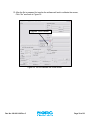
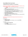
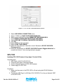
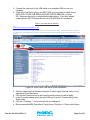
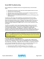
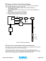
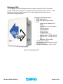
1
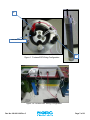
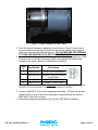
!"#$#%&& ESP Monitoring System !.%12-.(&$'11'$."(/'(3'1 ' ()*+%#%, - ' ()$./%, - % 0%#)$./%, NOTICE This manual is intended for private information only, with the understanding that any other use of the subject matter, in whole or in part, by reference or otherwise, shall be only with the prior knowledge and approval of Sercel-GRC Corp, and with the further understanding that this manual is for informational purposes only and that suggestions and recommendations contained herein shall not be understood or construed as a guarantee or warranty of any method, product or device. Federal copyright law protects the publication. No part of this publication may be copied or distributed, transmitted, transcribed, stored in a retrieval system, or translated into any human or computer language, in any form or by any means, electronic, magnetic, manual or otherwise, or disclosed to third parties without the express written permission of Sercel GRC Corp. Any questions concerning the content of this manual, equipment operation, field maintenance, maintenance assistance and operation or maintenance training courses should be directed to Sercel-GRC. Copyright © 2013 by Sercel-GRC Corp. All rights reserved worldwide. Document Number: 006-0211-00 Sercel-GRC Corp. 6540 East Apache Street, Tulsa, Oklahoma 74115-3616 USA P.O. Box 581570 Tulsa, Oklahoma 74158-1570 USA E-Mail: [email protected] or [email protected] Telephone: (1) 918-834-9600 / Fax: (1) 918-838-8846 Visit our web page at www.Sercel-GRC.com Document: 006-0211-00 Rev C Page 2 of 63 Table of Contents INTRODUCTION ............................................................................................................. 5 Customer Service/Support ........................................................................................... 5 BENCH TESTING AND VERIFICIATION PROCEDURES ............................................. 6 Tools Required ............................................................................................................ 6 Process Steps for Bench Test and Verification ............................................................ 6 INSTALLATION PROCEDURES FOR DOWNHOLE GAUGE ....................................... 8 Installing the ESP Sensor to the Motor ........................................................................ 9 Installing the Sensor Discharge Pressure Base Adapter (For ESP& QESP-3500 Gauge Models Only) .................................................................................................. 11 Installing the Resistance Temperature Detector “RTD” (For Non-Factory Installed RTDs, Probe Style) .................................................................................................... 13 Wye Point Replacement ................................................................................................... 15 INSTALLING THE SURFACE INTERFACE EQUIPMENT ........................................... 19 SCOUT-3000 Installation ........................................................................................... 19 SPS-3000 Installation ................................................................................................ 19 SPS-1500 Installation ................................................................................................ 21 SCOUT-2200 Installation ........................................................................................... 22 INSTALLING THE SURGE SUPPRESSOR AND SURFACE CHOKE ........................ 23 Surface Choke ........................................................................................................... 26 Surge Panel Protector/Suppressor ............................................................................ 23 Surface Choke and Surge Protector Panel Assembly #90B2175 .............................. 25 SCOUT-3000 RELAY ALARMS SETUP ...................................................................... 28 SOFTWARE AND FIRMWARE INSTALLATION AND UPDATES .............................. 31 Scout-3000 (for Rev. A Only) ..................................................................................... 31 Updating SPS Firmware Using Tera Term - TTermpro ..................................................... 31 Updating LCD Firmware ............................................................................................ 33 Scout-3000 (for Rev. B and Later Versions) .............................................................. 41 Updating RCM Firmware with Memory Tools & USB Cable .......................................... 41 SPS-1500 .................................................................................................................. 41 Updating SPS-1500 Firmware Using Hyper-Terminal Utility ............................................. 42 Updating SPS-1500 Using Tera Term - TTermpro............................................................ 45 Procedure for Viewing USB Memory with Memory Tools Software ........................... 46 4-20 mA CARD INSTALLATION AND CONFIGURATION .......................................... 48 Installing 4-20mA optional cards into the Scout-3000 ................................................ 48 Scout-3000 4-20mA Port Setup ................................................................................. 51 TROUBLESHOOTING .................................................................................................. 52 Sensor To Surface Communication Troubleshooting ................................................ 52 Scout-3000 Troubleshooting ...................................................................................... 53 SPS-1500 Troubleshooting ........................................................................................ 56 SCOUT and SPS Error Codes and Corrective Actions .............................................. 57 Document: 006-0211-00 Rev C Page 3 of 63 Table of Contents, cont. APPENDIX .................................................................................................................... 58 Surface Readout Status Message Summary ............................................................. 57 Fortress ESP Monitoring System Field Checklist....................................................... 58 ESP Gauge and Surface Control Interface Diagram.................................................. 59 Surface Readout Devices - Gauge Interface Specifications ...................................... 60 SPS-3000 ......................................................................................................................... 61 SPS-1500 ......................................................................................................................... 61 Scout-3000 ....................................................................................................................... 62 Datalogger-2000 .............................................................................................................. 63 Doc No. 006-0211-00 Rev C Page 4 of 63 INTRODUCTION This field installation manual will detail and explain the operation and installation of the Sercel-GRC FORTRESS ESP Monitoring System, including gauges: ESP-1000 ESP-1500 ESP-1800 ESP-2500 ESP-3500 QESP-2500 QESP-3500 SPS-3000 Surge Suppressor (Protector) Surface Choke and surface readout equipment: SCOUT-2200 SCOUT-3000 SPS-1500 In the Appendix of this manual is a copy of the FORTRESS ESP Monitoring System Field Checklist. This checklist will provide the installer with the ability to follow and record the installation of the monitoring system. Please follow this guide and use the checklist provided when installing the Fortress ESP Gauge System. Customer Service/Support If any assistance is needed please contact any of our service centers listed below. The engineers and technicians will be more than happy to provide you with any assistance needed. SITE LOCATION PHONE CAPABILITIES Tulsa, OK, USA 6540 E. Apache Street Tulsa, OK 74115 USA +1.918.834.9600 Headquarters, Engineering, Manufacturing, Sales, Service for USA and Canada Villahermosa, Mexico Comalcalco Num. 111 Fracc, Prados De Villahermosa, Villahermosa, Tabasco, Mexico C.P. 86030 993-312-7234 Sales, Service for Mexico Dubai, UAE Sercel Dubai Building ZC02/ZC03 - Blue Shed Area, P.O. Box 17523, Jebel Ali Free Zone Dubai, UAE +971 4 8832142 Sales, Service for Middle East Mumbai, India SK Oilfield Equipment Co Pvt Ltd. 26,Tarun Bharat Chakala, Andheri East, Mumbai, 400009 India 91 22 2837 7070 Sales and Service for India Singapore 65 6417 7000 Sales and Service for South East Asia/Australia Sercel Singapore 68 Loyang Way Singapore 508758 Document: 006-0211-00 Rev C Page 5 of 63 BENCH TESTING AND VERIFICIATION PROCEDURES Note: Bench test and verification procedures are applicable to all Fortress ESP gauges. Tools Required 110V Power Source Either a Sercel-GRC SCOUT-3000 (Surface Readout) o Portable Scouts will include a twisted wire pair with alligator clips Or a SERCEL-GRC SCOUT-2200 Bulkhead Cable Assembly Process Steps for Bench Test and Verification 1. SECURE THE GAUGE to keep the gauge from rolling or moving during testing. 2. Remove the top shipping cap from the Fortress ESP Sensor. 3. Inspect to make sure no liquid and/or debris is present. (If liquid or debris is present, contact Sercel-GRC). 4. Connect the red wire (Gauge Signal Wire) from the SCOUT to one of the 3 pins in the hockey puck as shown in Figure 1 “a”. See page 25 for Surge Panel connections. See figure 1A and 1B for an illustration of connections from Scout-3000 to Surge Panel to ESP Gauge. 5. Connect the white/black wire (Ground Wire) to the body of the sensor as shown in Figure 1 “b”. 6. This next step is applicable to all FORTRESS ESP Sensors EXCEPT the ESP-1800 and where the motor temperature sensor (Resistance Temperature Detector, “RTD”.) is not factory installed. 7. Locate the RTD kit (Probe Style or Threaded Style). 8. Locate the two white wires exiting the top of gauge. 9. Temporarily connect the two RTD wires to the two white wires exiting the gauge. (As there is no polarity, wires can be connected in any way). NOTE: Installation Procedure for the RTD connection can be found in the installation section. 10. Power up SCOUT (Red Switch to “On” position) a. Red switch illuminates indicating SCOUT is powered up. If switch light does not illuminate, check power connection and/or fuse. 11. SCOUT will begin auto-analyze steps (sync phase and analyze messages on display). 12. SCOUT will begin displaying gauge data in approximately 2-5 minutes. 13. Record the parameter readings on the Fortress ESP Sensor Checklist in the Appendix of this manual for test verification records. a. Bench Test Validation Parameters: i. Pressure: 0-40 psi ii. Temperature: ±5º F of ambient iii. Motor Temperature: ±7º F of ambient iv. Vibration (If Available): 0-1.2g Doc No. 006-0211-00 Rev C Page 6 of 63 a HOCKEY PUCK Figure 1: Fortress ESP Wiring Configuration b Figure 1A Fortress ESP Wiring Configuration Doc No. 006-0211-00 Rev C Page 7 of 63 Figure 1B: Fortress ESP Wiring Configuration The end of the 3-phase cable will come out somewhere in the center of the ESP cable spool as shown in Figure 1 above. Follow the steps below to test the gauge through the ESP cable spool once the cable has been connected to the motor. Since the SCOUT is powered by 110 VAC, an external power supply will be needed. Do not set the SCOUT on the Spooling unit as shown on this trailer. ONLY CONDUCT THIS CHECK WHILE THE SPOOL IS NOT MOVING. NEVER AT ANY TIME STEP OVER THE 3 PHASE ESP CABLE. 1. Connect the red wire (gauge signal wire) to one of the 3 phase leads. 2. Connect the white or black wire (ground) to the shielding on the 3 phase cable. 3. Power on the SCOUT. 4. Record the parameter readings on the Fortress ESP Sensor Checklist given in the Appendix of this Manual. 5. Repeat this for every 10 stands of completion tubing until the last tubing stand has been assembled. Doc No. 006-0211-00 Rev C Page 8 of 63 INSTALLATION PROCEDURES FOR DOWNHOLE GAUGE Installing the ESP Sensor to the Motor This procedure outlines the best practices that should be taken in the field. The sensor can be mounted to the motor before the motor is shipped to the field. In that case, the procedure will be the same, but probably not done on the back of a flat bed trailer as shown in these pictures. 1. Layout the sensor so that the three female connections on the Hockey puck are aligned with the three pins coming out of the motor, and the holes on the motor base are aligned with the holes on the motor head as shown in Figure 2. Figure 2. Aligning the motor pins to the Hockey puck. 2. Carefully stab the sensor onto the motor watching closely that the three pins mate up with the three female connections on the hockey puck. IT IS VERY IMPORTANT DURING THIS STEP YOU DO NOT TWIST THE SENSOR WHILE STABBING ONTO THE MOTOR BASE. DOING SO WILL RESULT IN DAMAGING THE HOCKEY PUCK AND RUINING COMMUNICATION TO THE SENSOR ONCE THE MOTOR IS STARTED. Doc No. 006-0211-00 Rev C Page 9 of 63 Figure 3. Gauge stabbed into motor base. 3. Once the sensor has been stabbed as far as shown in Figure 3, place one of the motor base bolts through the bolt hole and into the sensor motor head to make sure that the bolt holes are lined up. DO THIS BEFORE PROCEEDING TO STAB THE SENSOR FULLY ONTO THE MOTOR BASE. 4. Use of the fill and plug valve to fill the gauge with oil from the gauge plug. Most customers do not use the fill and plug valve on the gauge and use the one located on the motor. Below is a description of the plug: Item # 1 2 Part Number Description 089-0252-00 089-0254-00 PLUG, VENT & DRAIN GASKET, VENT & DRAIN LEAD SEAL VALVE, DRAIN & FILL GASKET, LEAD SEAL 3 4 089-0251-00 089-0253-00 Note: Both gaskets listed above are single-use components. Item 3 (valve) should be torqued to 210 in-lbs and Item 1 (plug) should be torque to 100 in-lbs. 5. Connect the SCOUT to the motor and gauge assembly. Connect the red wire (gauge signal) to one of the motor lead power connections and the white or black wire to the motor housing. 6. Record the parameter readings on the Fortress ESP Sensor Checklist. Doc No. 006-0211-00 Rev C Page 10 of 63 Testing the ESP Sensor While Installing Tubing Figure 4. Spooling Unit. Installing the Sensor Discharge Pressure Base Adapter (For ESP& QESP-3500 Gauge Models Only) Discharge Port Connection All Dual Pressure gauges are equipped with a Discharge Pressure Port. The Discharge Pressure Port must be purged with motor oil, vent plugged, and connected to the hydraulic tubing connecting to the pump discharge sub before being deployed. Failure to install the Discharge Bleed Plug will result in failure to read the discharge pressure. See Installation and Troubleshooting guide for instruction to purge discharge pressure port connections. Discharge Pressure Bleed Port Plug Must be INSTALLED before running gauge into the well. Compression Fitting 1/8” NPT to ¼” inch capillary tubing Figure 5. Discharge tubing connection. Doc No. 006-0211-00 Rev C Page 11 of 63 THIS OPERATION NEEDS TO BE COMPLETED IN ITS ENTIRITY BEFORE THE MLE IS CONNECTED TO THE MOTOR. 1. 2. 3. 4. Remove the fitting and ensure that the NPT threads have been Teflon taped. Install the n fitting back into the base. Remove the compression nut and ferrules. Install compression nut and ferrules onto the capillary tubing ensuring the correct ferrule orientation. 5. Place the capillary tubing with nut and ferrule into the fitting and tighten until one thread only is visible on the fitting or until the fitting is hand tight using a 9/16” end wrench. 6. Nipple up BHA and Discharge Sub. 7. Leave the fitting on the discharge sub hand tight so that it will leak fluid slightly. 8. Once the BHA and discharge sub is installed, POOH BHA and connect a pressure test system to the Discharge pressure bleed port. 9. Remove pressure test system and install plug in port. 10. Fill the line with hydraulic fluid until fluid exits the pressure bleed port. 11. RIH BHA and tighten the pressure fitting on the discharge pressure port. 12. POOH BHA and remove plug from port. 13. Immediately install the pressure test system and pressure test to 5Kpsi for 10 min. 14. If the pressure remains constant +/- 20 psi, then the installation is complete, if not, then repeats Steps 1-13. Megger testing motor and cable The motor and cable may be Megger tested if required using the following guidelines: The output voltage of a Megger will exceed the breakdown voltage of the protective MOV mounted on the fuse block. The MOV will conduct if a Megger is used, giving incorrect readings. Disconnect the three-phase choke and fuse block from the motor cable before testing. Do not Megger test the downhole equipment while any of the surface components are connected to the motor power cable. NOTE: MEGGER TEST THE SENSOR IN REVERSE POLARITY ONLY!! Doc No. 006-0211-00 Rev C Page 12 of 63 Installing the Resistance Temperature Detector “RTD” (For Non-Factory Installed RTDs, Probe Style) All ESP Gauges monitor Motor Temperature with a Platinum 1K RTD. There are several RTD Motor Temperature Probe options including Probe, Threaded, and customer supplied. Motor Temp probes are mounted inside the gauge assembly and placed against the Motor Windings for maximum temperature transfer and fast response. Motor Temperature Sensors can be ordered as an accessory or wired permanently inside the gauge eliminating field connection concern. The following procedure appears much more complex than it actually is and can be performed in either the field or shop environment. Also included in this document is the wye point solder procedure that Manufacturing uses. Motor RTD Connection Instructions a. The first step is to determine where the RTD is going to be placed. It can be either inside the ESP motor oil passage or inside the Sercel-GRC gauge. Inside the gauge is the safest and is the least likely to come in contact with rotating motor components, but it will be slower in responding to temperature variations of the ESP motor. Placing the RTD inside the motor oil passages provides faster response times to temperature changes, but runs the risk of contacting rotating parts. b. Shorten the two wires coming from the gauge for the RTD to match where you have determined to place the RTD. If it’s going inside the motor oil passage secure the wiring and its excess to insure that the RTD is not drawn further into the oil passage by the oil flowing through it. This prevents the RTD from coming in contact with the rotating internal parts of the motor. Also insure that the wiring will not come in contact with the end of the rotating motor shaft located where the motor and ESP gauge are mated together. If the RTD is being placed inside the gauge do not coil up the excess wire inside gauge but instead shorten the wires and then insert the RTD and wiring back into the gauge. The reason for not coiling the excess wire up and placing it inside the gauge is this can possibly allow motor noise to show up on the motor temperature readings. c. Strip 1/4” to 3/8” of insulation from the RTD and gauge wires. d. Cut a piece of high temp heat shrink tubing, around 2.5”, and slide it over and past both stripped gauge wires. e. Using two more pieces of high temperature heat shrink tubing, around 1.5” long, slide each piece over and past each individual gauge wire. The result should look like the example in Figure 6. Doc No. 006-0211-00 Rev C Page 13 of 63 Figure 6. Three pieces of shrink tubing on gauge wires. f. Twist one RTD wire and one RTD gauge wire together creating a splice so that it appears as a straight wire and not two wires side by side. At this time solder the two wires together using high temp solder. Do the same step for the other two wires (one from the RTD and the other from the gauge). g. Slide the heat shrink tubing down over each individual soldered bare wire and heat shrink the two pieces of tubing using a hot air gun (heat gun). The solder joint should be located in the center of the length of the tubing and the result should appear as shown in Figure 7. h. From step c, now slide the longer piece of heat shrink tubing over both wires so that the solder joint is centrally located inside the tubing as shown in Figure 8. Solder joint located at the center of the heat shrink tubing. Figure 7. Heat shrink tubing over solder joints. Doc No. 006-0211-00 Rev C Page 14 of 63 Figure 8. Long piece of heat shrink tubing over both wires. Finally, replace the wye point if you have removed it. Attach the Scout-3000 or portable Scout to any of the motor terminals of the wye point or to the gauge wire if not using our wye point. Turn on the Scout and check/record gauge readings. Place the RTD in the position you had determined and reassemble the gauge and motor. Re-check and record readings using the Scout attached to the top of the motor on one motor lead. Wye Point Replacement If you do have to remove the wye point, below is the GRC procedure that is used when Manufacturing is attaching the wye point. Purpose The purpose of this procedure is to give instructions on how to solder the communication wire to the WYE terminal for ESP gauges. Cautions and Warnings Ensure there are no nicks on the conductor of the communication wire when stripping. Ensure there are no sharp edges on solder joint of wire and terminal. Ensure shrunken heat shrink does not back off from the terminal. Read entire procedure before initiating procedure. Equipment needed 2 Heat Shrink Wraps 1 ½ inches long, P/N: 133-0051-00 Needle nose pliers Heat Gun High Temperature Solder, P/N: 140-0001-00 Flux Isopropyl Alcohol WYE Adapter Communication Wire (From Assembly 90C2025, not to be confuse with the RTD white wire) Terminal, P/N: 90B1863 Doc No. 006-0211-00 Rev C Page 15 of 63 Procedure Cut P/N 037-0050-04 off from the communication wire, refer to Appendix Fig. A1. Thread the communication wire through the hole on the terminal. Be sure not to use the RTD wires as all wiring from the choke is white. Fold the excess wire back towards itself making a loop. Refer to Figure 52. Figure 9. WYE Connector Shown with the Communication Wire Prior to Crimping. Any excess wire extending beyond the insulation of the wire should be removed. Before soldering, gently crimp the wires with needle nose pliers to close the gap of the wire loop. Refer to Figure 10. Figure 10. WYE Terminal Shown with the Communication Wire After Being Crimped. Doc No. 006-0211-00 Rev C Page 16 of 63 Now solder the wire to the terminal with the aid of flux making sure not to leave any sharp edges. Refer to Fig. 11. After soldering, clean the solder with alcohol and slide the clear plastic wire insulator to the solder joint. Refer to Fig. 11. Figure 11. WYE Terminal Shown with the Communication Wire Soldered. Slide one piece of heat shrink tubing down to the hex base of the terminal. Apply heat to shrink the first heat shrink tubing before applying second layer of heat shrink tubing. Refer to Figure 12. Figure 12. WYE Connector Shown with the First Heat Shrink Tubing Un-Shrunk. Doc No. 006-0211-00 Rev C Page 17 of 63 Now slide the second piece of heat shrink tubing down to the base of the threaded pin. This will go over the first heat shrink tubing. Refer to Fig. 13a. Figure 13. WYE Connector Shown with the Second Heat Shrink Tubing. Apply heat to the heat shrink to complete the assembly. Refer to Fig.13b for final assembly. Figure 13b. WYE Connector Terminal Shown with Both Heat Shrink Tubing Shrunk. Doc No. 006-0211-00 Rev C Page 18 of 63 INSTALLING THE SURFACE INTERFACE EQUIPMENT SCOUT-3000 Installation Figure 14 shows a typical wiring and installation schematic for the ESP surface equipment. Figure 15 describes the specific connections of a Scout-3000 to a gauge. Connections are also detailed for the 4-20mA Current Loop and Modbus. Figure 14. SCOUT and Suface System Wiring Diagram ! CAUTION ! Lethal Voltages Present Inside Enclosure. Remove power anytime the front panel of the Scout-3000 is removed. There are potentially dangerous voltages present! Doc No. 006-0211-00 Rev C Page 19 of 63 Signal Name Recommended Wire Colors AC Power-In Black-Live, White-Neutral, Green-Earth Gnd Gauge Red-Signal (+), Green-Return (-) 4-20mA #1 Orange/Gray (Connections for Scout-3000 w/ Optional 4-20mA Current Loop) Blue/Violet (Connections for Scout-3000 w/ Optional 4-20mA Current Loop) Blue/Violet Modbus (Connect to Pins 1 and 4) Figure 15. Scout-3000 Wiring and Connections 4-20mA #2 SPS-3000 Installation The connections for the SPS-3000 are shown in Figure 16 below. Gauge: +Connection to ESP gauge signal. –Connection to dedicated wellhead ground. VDC: Connections to a +12 to 18VDC and Ground. ModBus: TR- and TR+ Connections to ModBus master SPS-3000 Sig+ Grd- 12-18V Grd TR+ TR- + + + Panel Surge + +Power + + + +Master ModBus (to Wellhead Ground) Supply 12-18 VDC or 485 Converter TR+ TR- + +ModBus + Slave Figure 16. SPS-3000 Connections Doc No. 006-0211-00 Rev C Page 20 of 63 SPS-1500 Installation Illustrations on how to install the SPS-1500 is shown in Figure 17 below. USB Connection Gauge Fuse: 5x20mm 100mA Fast Acting Orange LED: Gauge Data Byte Green LED: Gauge Data BIt Gauge Fuse Gauge Comm. Bi-Color LED Power/Gauge Connections RS-485 / RS422 Modbus Slave Power/Modbus Bi-Color LED USB PC Connection Power/Gauge 1: Gauge Signal 2: Well Ground 3: Vdc Ground 4: Vdc +12 to 28V Blue LED: Power Red LED: Modbus Traffic RS-485/422 1: TR 2: TR + 3: TR + 4: TR - Gauge signal fuse, 100mA fast acting 5x20mm, GRC P/N 0430042-00 Flashes green for every gauge data bit received Flashes orange for every gauge data byte received 1. Gauge Signal 2. Gauge Signal Return/Wellhead Ground 3. Vdc Ground 4. Vdc Power +12V to 28V DC RS-485: Install (2) Jumpers | RS-422: Remove (2) Jumpers 1. TR | 1. T2. TR + | 2. T+ 3. TR + | 3. R+ 4. TR | 4. RSolid blue when power is connected Blinks Red when a ModBus request is received Modbus and firmware updating via USB Virtual COM Port Figure 17. SPS-1500 Connections. Doc No. 006-0211-00 Rev C Page 21 of 63 SCOUT-2200 Installation For installations using a SCOUT-2200 ESP Surface Monitoring System, the installation and operations manual can be found on the Sercel-GRC website at www.sercelgrc.com. Doc No. 006-0211-00 Rev C Page 22 of 63 INSTALLING THE SURGE SUPPRESSOR (PROTECTOR) AND SURFACE CHOKE The ESP gauge surface readout equipment such as the Scout-3000 connects to the downhole tool via the motor power cable through the Surge Suppressor and Surface Choke. Communication and power are provided via a “Comms-On” technique; meaning the communication and power are both transmitted through the motor cable. The surface readout equipment provides “Comms-On” power to the ESP gauge and is connected to the ESP Surge Protection Equipment via the gauge signal and wellhead ground. Surface Choke The surface choke, shown in Figures 18a/b, is connected between the VSD 3-phase power and the Surge Panel or Surge Protector. The purpose of the surface choke is to allow the ESP Gauge Interface to provide power to and communicate with the downhole tool. The ESP Gauge Interface provides between 30-80VDC to the Neutral wire on the Surface Choke to power the downhole gauge. The Surface Choke is designed to block AC voltages from entering the ESP Surface Equipment as well as creating a virtual ground via WYE point for direct connection for Downhole communication. Three Phase Motor Power Connection Neutral or WYE Figure 18a. Surface Choke Photo. Part Number #99B990. Doc No. 006-0211-00 Rev C Page 23 of 63 Figure 18b. Three Phase Surface Choke Connections Surge Panel Protector/Suppressor The Surge Panel provides protection for the ESP Surface Interface equipment from several failures including; overvoltage from imbalance, transient voltage pulses, and switching spikes. User Replaceable 1/2A HV Fuse User Replaceable MOV – Recommended replacement anytime fuse is replaced Figure 19a. Surge Protector Photo. Doc No. 006-0211-00 Rev C Page 24 of 63 Figure 19b. Surge Protector Schematic and Connections Late model Surge Panel Protectors have a bleed resistor installed across the MOV (pin7 to pin 8) to dissipate static line charges. Surge Protector/Fuse Block Connections 1 - 8 1. No Connection 2. Gauge signal wire to SPS-1500 or Scout-3000 3. No Connection 4. To three-phase choke Y-point 5. No Connection 6. Gauge ground to SPS-1500 or Scout-3000 7. Dedicated wellhead ground 8. No Connection Assembly Connections 1. Once the tubing is installed and the cable is terminated at the junction box, check the sensor with the SCOUT at the junction box. This will ensure that everything is good downhole and the rig crew can proceed with their rig down. 2. Record the parameter readings on the Fortress ESP Sensor Checklist. 3. Mount the Surface Choke and Surge Protector (Suppressor) inside the transformer cabinet. 4. Reference Figures 18 & 19 to see the electrical connections. Surface Choke Tips 1. Make sure that the Surface Choke wires that are connected to the transformer are braided. 2. If longer cable is needed from the Transformer to the Surface Choke, make sure that it is rated for the Transformer voltage. 3. Each wire from the surface choke connects to one phase of the transformer. Doc No. 006-0211-00 Rev C Page 25 of 63 Surface Choke and Surge Protector Panel Assembly #90B2175 Surface Choke Interface to motor power cable Surge Protector Assembly 3 Phase Fuse Assembly Figure 20. Combined Surge Protector and Surface Choke Panel Doc No. 006-0211-00 Rev C Page 26 of 63 Surface Interface Connection to Scout or SPS-1500 Red – Gauge Signal Black – Gauge Ground Motor Wire Connection Green – WHG (Wellhead Ground) Phase A, B, C Figure 21. Surface Choke and Surge Protector Wiring Diagram Doc No. 006-0211-00 Rev C Page 27 of 63 SCOUT-3000 RELAY ALARMS SETUP The Relay Alarms Setup menu allows high/low trip points to be set for alarms. If the Scout-3000 was purchased with an optional relay board, the relay contacts will close when the alarm trips, allowing control of external equipment via the alarms. If you do not have the optional relay board, you may still use the relay alarms to log events to the USB drive showing alarms on the Scout-3000 display. Figure 22. Relay Alarm Setup Screen Up to 6 different thresholds can be set by pressing the arrow next to the Edit Alarm Thresholds text. You can select the parameter, less than or greater than, and edit the trip level on this screen. The Alarm Trip Delay value allows you to pick a time to delay before tripping the alarm. The parameter must trip for more than this time before the alarm trips. This is useful if you want to ignore small transients, and only want it to trip if Motor Temperature exceeds 270°F for at least 5 minutes (for example). You can also disable the alarms, or set it to trip instantly (no time delay) with this setting. See Figure23 to see the available options. The current status of all alarm thresholds is displayed on the Relay Alarm Setup screen as well. The threshold setting is shown on the left, and the latest value is shown on the right. A green value means the threshold has not been exceeded. A red value means the trip threshold has been reached. If an alarm trip delay is programmed and the delay time has not been reached, the value with also show “DELAYED X min”, meaning the threshold has been reached for X minutes (but the time delay has not been reached, so the alarm has not occurred yet). Doc No. 006-0211-00 Rev C Page 28 of 63 Figure 23. Select Alarm Trip Delay Screen When at least one threshold is reached for at least the Alarm Trip Delay time programmed the alarm trips. When the alarm trips, the following events occur automatically: 1. If the relay board is installed as an option, the relay contacts close. 2. A short 5 second alarm is sounded on the Scout-3000 (the volume is the same as is set in the Display/Sound menu). 3. The event is recorded to the USB thumb drive in a file called “ALARMLOG.CSV”. The file is appended with one line, in a comma-separated text format, showing the information about the alarm. An example of one trip event in the file is: "TripTime=Jan 27, 2011 Thu 09:35:00","Tool= 94351 MultiESP","Alarm=Motor Temp > 250.0 °F","LastValue=253.0 °F" 4. All data values on the main Scout-3000 screens turn red and the bottom right corner of the screen flashes “ALARM TRIPPED!” Pressing the “ALARM TRIPPED!” text takes you directly to the Relay Alarm Setup menu screen. Doc No. 006-0211-00 Rev C Page 29 of 63 Figure 24. Data Screen with the Alarm Tripped 5. The Relay Alarm Setup screen changes to show the details of what tripped the alarm. Figure 25. Relay Alarm Setup with the Alarm Tripped To clear the alarm once tripped cycle power to the Scout-3000. This will also reset the optional relay board if installed. Doc No. 006-0211-00 Rev C Page 30 of 63 SOFTWARE AND FIRMWARE INSTALLATION AND UPDATES Scout-3000 (for Rev. A Only) Updating SPS Firmware Using Tera Term - TTermpro Parts Required: 1. USB A-B CABLE 2. TTL CONVERTER 3. TTERMPRO UTILITY Procedure: 1. 2. 3. 4. 5. Use USB A-B cable between computer and TTL converter. Attach TTL converter to J3 (small ribbon cable is located on this header) Open TTERMPRO Select SERIAL BUTTON DROP DOWN BOX and SELECT USB SERIAL PORT (See Figure 26) Figure 26. Select USB Serial Port. 6. OK 7. SETUP MENU then SERIAL PORT to check the SERIAL PORT SETTINGS. See Figure 27. a. PORT: Select Com Port b. DATA: 8 Bit c. PARITY: NONE d. STOP: 1 BIT e. FLOW CONTROL: NONE Doc No. 006-0211-00 Rev C Page 31 of 63 Figure 27. Serial Port Settings. 8. Select OK 9. SHIFT-U and power up the Scout-3000 10. FILE TRANSFER XMODEM SEND 11. Screen shows BEGIN TRANSFER and “C” 12. Select file MODBUS 32.BIN from whatever location you have it stored in and DOUBLECLICK. 13. File begins transferring. See Figure 28. Figure 28. Files transferring. 14. File transfer is completed. See Figure 29. Doc No. 006-0211-00 Rev C Page 32 of 63 Figure 29. File transfer completed. 15. Close TTERMPRO 16. Power down Scout-3000 17. Remove TTL Convertor and re-attach ribbon cable to last two pins on the right side of J3. 18. Reinstall Scout-3000 faceplate. Updating LCD Firmware Parts Required: 1. USB Cable Type A to Type B Mini 2. BMPLoad software 3. Latest firmware version (90A2330) for the Scout-3000 SLCD_Firmwarexx.FWU Procedure: 1. Remove the Scout-3000 front panel. 2. Disconnect the wiring harnesses from J1 and J2 across the top of the back side of the LCD. 3. Plug USB Type B Mini cable from PC to J3 Mini USB socket on the left side of the LCD. 4. Open the screen update software “BMPLoad” program. See Figure 30. Doc No. 006-0211-00 Rev C Page 33 of 63 Select Comm port Change Baud Rate Connect Figure 30. BMPLoad Software. 5. Select the Comm Port associated with the USB connection. 6. Change the Baud Rate to 460800. 7. Click “Connect”. Doc No. 006-0211-00 Rev C Page 34 of 63 Load File Button SLCD Status Message Figure 31. BMPLoad software checking the SLCD status. 8. Verify SLCD Status shows ‘Connected’. 9. Click “Load from File” and the Open screen will appear, change the file type to Combined Upgrade .FWU. See Figure 32a. Doc No. 006-0211-00 Rev C Page 35 of 63 Change File Type to Combined Upgrade [*.FWU] Figure 32a. Changing the file type. 10. Select Firmware file “Scout-3000 SLCD_Firmwarexx.FWU” and click “Open”. See Figure 32b. Select Firmware file “Scout-3000 SLCD_Firmwarexx.FWU” Figure 32b. Selecting the right firmware for the Scout-3000. Doc No. 006-0211-00 Rev C Page 36 of 63 11. A message will appear that indicates the binary file is ready to be transferred. Click “OK” 12. Click “Store into SLCD” to begin transferring the file to the LCD. See Figure 33. The SLCD status screen will indicate the file transfer as shown in Figure 34. Click “Store into SLCD” to begin transferring the firmware to the LCD Figure 33. Transferring the firmware for the LCD. Doc No. 006-0211-00 Rev C Page 37 of 63 The SLCD Status screen will indicate the file transfer. Figure 34. SLCD status screen indicating the LCD file transfer. Doc No. 006-0211-00 Rev C Page 38 of 63 13. After the file is prepared for transfer the software will ask to calibrate the screen, Click “No” as shown in Figure 35. Calibrate Touch Screen - NO Figure 35. Do not calibrate the touch screen. Doc No. 006-0211-00 Rev C Page 39 of 63 14. After Clicking “No” the software will show the LCD is programmed. Click “Quit” to exit the program. See Figure 36. SLCD Status screen will show the program was successfully transferred. Click “Quit”. Figure 36. Final screen showing that the program was transferred successfully. 15. Disconnect the USB Cable from the LCD and reattach the wiring harnesses to the LCD ports and close the front panel. Doc No. 006-0211-00 Rev C Page 40 of 63 Scout-3000 (for Rev. B and Later) Updating RCM Firmware with Memory Tools & USB Cable NOTE: THIS PROCEDURE ONLY WORKS WITH REV. B SCOUT-3000 AND LATER VERSIONS, NOT WITH REV. A VERSIONS OF THE SCOUT. 1. Open Memory Tools and select drop down box located on second toolbar from the top. 2. Scroll down to Scout-3000 and select. 3. Go to PREFERENCES and select Scout-3000 Interface. 4. Select the correct Com Port that your laptop is using, Baud Rate=115200, Parity=NONE, Data Bits=8 and Stop Bits=1. Click APPLY. 5. Go to PREFERENCES, then to PROGRAM MODE and pick DIAGNOSTIC. 6. Enter password: XGRCService 7. Select REAL TIME from the tool bar. 8. Select RCM UPGRADE button at bottom of screen. 9. Select the location that Scout-3000 RCM Firmware xx.bin is located at and then select OPEN. 10. Follow the screen prompts. NOTE: SCOUT-3000 RCM UPDATE WORKS WITH BOTH REV.A AND REV.B SCOUT-3000 Parts Required: 1. USB to 232 Adapter 2. Programming Cable (has two headers, use the one marked PROG) 3. Rabbit Field Utility Procedure: 1. Open Rabbit Field Utility (RFU) 2. Open SETUP 3. Open COMMUNICATIONS and See Figure 37. Doc No. 006-0211-00 Rev C Page 41 of 63 Figure 37. RFU in the Communications Options 4. Select USE SERIAL CONNECTION button. 5. Select 115200 from BAUD RATE DROPDOWN BOX. 6. Select correct com port from the COMM PORT DROPDOWN BOX. 7. Clear ENABLE PROCESSOR DETECTION CHECKBOX. 8. Check USE USB TO SERIAL CONVERTER CHECKBOX. 9. Click OK 10. Select FILE from the top toolbar. 11. Select LOAD FLASH IMAGE 12. Select file from wherever it has been stored. Standard is SCOUT-3000 RCM Firmware xx.bin 13. Some GE installations use SCOUT-3000 RCM Firmware 20ggemodbus.bin for use with the Vector 7 drive running the basic program. SPS-1500 Updating SPS-1500 Firmware Using Hyper-Terminal Utility Parts Required: 1. USB Cable, A-B (P/N 136-0076-01) 2. Computer with Hyper-Terminal software 3. Current released version of SPS-1500 firmware 4. Power supply for SPS-1500 Procedure: 1. Make sure the power to the SPS-1500 is off and unplug the RS-485 Modbus interface. 2. Connect the USB Type A to B Cable (P/N 136-0076-01) to the port labeled “USB” on the SPS-1500. Doc No. 006-0211-00 Rev C Page 42 of 63 3. Connect the other end of the USB cable to an available USB port on your computer. 4. If this is the first time to plug in the SPS-1500, you may need to install drivers (SEE SCOUT-3000 USB SERIAL DRIVER SECTION BELOW in Figure 38). Windows should try to automatically install drivers. If this fails, please contact Sercel-GRC Customer Service at (918) 834-9600 for assistance. SCOUT 3000 USB SERIAL DRIVER Go to: http://www.ftdichip.com/FTDrivers.htm Select the Operating System that matches the PC you are using. Normally, when the Scout is connected to a PC that is connected to the internet, the PC will automatically download the appropriate driver from the site. Figure 38. Scout-3000 USB Serial Driver Installation. 5. Start the HyperTerminal software using the "Launch HyperTerminal" button or by selecting it in the Start menu. 6. Click on the Properties icon in the HyperTerminal toolbar (on the far right). 7. In the Properties dialog select the new COM port from the "Connect using" drop down menu. 8. Click the "Configure..." button and set the port settings to: 9. Bits per second=9600, Data bits=8, Parity=None, Stop bits=1, Flow control=None Doc No. 006-0211-00 Rev C Page 43 of 63 10. Press and hold the "Shift" and "U" keys on the computer keyboard while simultaneously turning the SPS-1500 power on. You should soon see "BEGIN TRANSFER" displayed in HyperTerminal. If you do not, power down the SPS1500 and repeat this step. 11. Select "Send file..." from the "Transfer" option on the HyperTerminal menu bar. 12. In the dialog box that opens select the file that contains the SPS-1500 firmware, set the protocol to "X modem", and press "Send". 13. When the transfer is complete, remove power from the SPS-1500, disconnect the USB cable and reconnect the RS-485 interface. 14. Power the SPS-1500 back on and verify the new firmware version is displayed on the LCD screen. Doc No. 006-0211-00 Rev C Page 44 of 63 Updating SPS-1500 Using Tera Term - TTermpro 1. Open TTERMPRO 2. Select SERIAL BUTTON 3. Drop down box and select USB SERIAL PORT and COM PORT NUMBER found under CONTROL PANEL/DEVICE MANAGER/PORTS. 4. OK 5. SETUP MENU then SERIAL PORT. See Figure 39. a. PORT: Select Com Port b. Baud Rate: 9600 c. DATA: 8 Bit d. PARITY: NONE e. STOP: 1 BIT f. FLOW CONTROL: NONE 6. Select OK Figure 39 TTERMPRO Serial Port Setup. 7. Depress SHIFT-U while powering up the SPS-1500. You should see the screen in Figure 40. Doc No. 006-0211-00 Rev C Page 45 of 63 Figure 40. 8. On the Tera Term toolbar select FILE-TRANSFER –XMODEM-SEND 9. Go to file location and choose 90A3141-MODBUS (SPS 1500) to open location. 10. Select SPS-1500_20g.BIN and then click OPEN which will begin transfer as shown in Figure 41. Figure 41. Transferring firmware file. 11. Screen will say TRANSFER COMPLETE when done. 12. Power the SPS-1500 off and then back on and you will see the firmware version on the display. Doc No. 006-0211-00 Rev C Page 46 of 63 Procedure for Viewing USB Memory with Memory Tools Software Viewing Data On A Computer 1. Open Memory Tools program. 2. Click on READ Button at top of page, choose the file on the USB memory you would like to see. 3. Open file, then click on SAVE. 4. Click YES then SAVE. 5. To see the Well Test Data 6. Click the WELL TEST DATA tab. 7. Click on OUTPUT FORMAT box, choose the format that you would like to see. 8. To Export Data in Excel Format 9. Click on FILES 10. Click on EXPORT 11. Choose CSV ASCII 12. Check HEADER and COLUMN box 13. Click on SAVE FORMAT and choose the one you like. 14. Click on SAVE 15. Create a file name 16. Click on SAVE 17. Now the data you have selected is in Excel format. Doc No. 006-0211-00 Rev C Page 47 of 63 4-20 mA CARD INSTALLATION AND CONFIGURATION Installing 4-20mA optional cards into the Scout-3000 Figure 42 labels the main components of the Scout-3000. The procedure follows. SPS Module (Gauge Power Supply) RCM (control module for Scout-3000) Gauge Signal and Signal Return Connections Modbus module Connecti on 4-20mA Current Loop Module Connection Earth Ground Connection Graphing Memory Backup Battery AC Power Input Connection Figure 42. Scout-3000 Internal Subcomponent Identification. 1. Install a 4-20 mA card 99B470 into J8 (4-20 mA) connector on the Scout mother board and secure it with the standoff included in kit as shown in Figures 43 & 44. 4-20mA Current Loop Module Connection Figure 43. 4-20 mA module. Doc No. 006-0211-00 Rev C Page 48 of 63 Install standoff here Figure 44. Standoff placement. 2. Check switch position on 4-20 mA card to verify it is configured properly as shown in Figure 45. 4-20mA Switch position If a second 4-20 mA card is installed, the upper card will have this switch in the opposite position. The lower card will have the switch in the position shown. Figure 45. Switch Position. 3. Wire 4-20 mA current loop with power supply. Figure 46. 4-20 mA Receiver Figure 46. 4. Install Relay card and secure with 4-40 screw provided. Figure 47. Install screw here Figure 47. Screw position. Doc No. 006-0211-00 Rev C Page 49 of 63 5. Check switch position on relay card to verify its position is correct as shown in Figure 48. Relay Switch position Figure 48. Check switch position on relay card. 6. Connect the signal wires to the relay card as shown below. Normally Closed contact Common contact Normally Open contact Figure 49. Signal wires connection. 7. Configure the Analog Card and Relay Card in the Scout Ports menu as detailed below. The Ports menu is under the Menu tab on the Scout-3000 Home Screen. Doc No. 006-0211-00 Rev C Page 50 of 63 Scout-3000 4-20mA Port Setup The 4-20mA Port Setup menu allows you to configure the optional 4-20mA current output loops. The term Channel reflects which gauge sensor is connected to the current loop. The single 4-20 mA card is channel 1. The 4 mA allows you to set the value that the 4 mA of current will reflect. In the example in Figure 50, a reading of 0.0 PSI will output 4 mA. The 20 mA allows you to set the value that the 20 mA of current will reflect. In this example, a reading of 5000.0 PSI will output 20 mA. Alarms: It is possible to set high and low trip alarm points on the 4-20 mA current loops. In this example, a reading under -5.0 PSI or above 5050.0 PSI will trip the alarm For example, you could setup a SCADA system to turn the motor off if 12.0 mA current is received which could represent a particular intake pressure. Note: The 4-20 mA current loops can actually output 0 to 24 mA, so this alarm current could be set outside the 4-20 mA range for easy detection. Trim 4.00 mA and Trim 20.00 mA allow you to calibrate the 4-20 mA output with your loop measuring equipment. Select Trim 4.00 mA and adjust the setting until your system reads as close to 4.00 mA as possible. Select Trim 20.00 mA and adjust the setting until your system reads as close to 20.00 mA as possible. Figure 50. Scout-3000 4-20mA Current Loop Configuration Menu Doc No. 006-0211-00 Rev C Page 51 of 63 TROUBLESHOOTING Sensor To Surface Communication Troubleshooting The definitive method for troubleshooting installation problems is to separate the downhole equipment from the surface equipment, including the junction box and surface cable. Once this is done the ability is gained to truly see where the problem lies with the installation. THE USE OF A MEGGER IS STRICTLY PROHIBITED DURING THIS TEST UNLESS ALL OTHER AVENUES ARE EXHAUSTED. IT IS NECESSARY TO CONTACT A GRC SERVICE ENGINEER BEFORE ANY MEGGER TESTING IS EXECUTED. Troubleshooting Steps It is recommended to use a known functioning portable SCOUT unit for this exercise. 1. Record display screen information or error messages. 2. Insure all power going downhole is shutdown. FAILURE TO DO THIS WILL RESULT IN INJURY, DEATH AND DAMAGE TO EQUIPMENT. 3. Shut down power at the surface display so that no voltage is applied to the Surge Suppressor/Choke assembly. 4. Check to insure there is no voltage present at the Surge Suppressor/Choke assembly. Visually inspect for damage/discoloration of components and wiring. Then conduct individual resistance checks of the fuses, MOV and Surface Choke. a. All components should be isolated from the rest of the circuit while checking; this will prevent a false reading b. MOV should read infinite in both directions when checked with a multimeter. c. Fuses should check less than 2 ohms except for the fuse in the Scout3000, which will read approximately 12 ohms. d. Surface Choke should read approximately 260 ohms phase to phase and 130 ohms phase to neutral wire. 5. Depending on the type of wellhead penetration used, separate the downhole cable from the surface cable at the wellhead. If the downhole cable continues to the surface junction box (i.e. no cable termination at the wellhead) the test may be performed there. Disconnect the surface cable going from the junction box to the transformer in this case. 6. Perform phase to phase resistance checks of the cable and record the values and record. 7. Attach the positive lead of the portable surface display to one of the three phases and the negative lead to a good clean wellhead ground. 8. Power the portable surface display on and allow the system to boot up and to go through the analyzing process. If the system does not complete the analyzing step, record the errors shown and compare it to the Scout-3000 Error Chart. 9. If errors are being seen, one corrective measure to try is to change the Line Voltage value, to both a lower and higher value by putting the SCOUT in Manual Mode. This is shown in the section “SCOUT-3000 Operation Settings” Doc No. 006-0211-00 Rev C Page 52 of 63 Scout-3000 Troubleshooting Before attempting to troubleshoot there are a few general items you should double check: Check that all connections to the fuse block and three phase choke are correct. Check the fuse on the fuse block. Check the fuses in the Scout-3000 (line circuit breaker and gauge signal fuse). Check for a short circuit in the motor power circuit. Make sure you have a dedicated ground wire from the Scout-3000 directly to the wellhead ground. If the Scout is still having trouble establishing communications with the tool after checking the above problems try restoring/rebooting the Scout by going to the SPS Menu and selecting the Restore option, followed by the Reboot option. If this does not work, try to manually set the operating parameters. Turn off the Auto Volt and Auto Analyzer and begin stepping the voltage from 40 V to 80 V to see if that doesn’t solve the problem. The SPS is susceptible to faults caused by phase imbalances that can result in AC voltage at the gauge signal connection point. Phase imbalance voltages can result in tool communication problems. In addition, if the voltages at the gauge signal connection is higher than the rated signal fuse, it will result in a blown fuse. If this situation occurs, disconnect the Scout-3000 from the Surface Package and troubleshoot the phase imbalance situation before attempting further communications with the tool. Note: The ESP gauge will not operate if any phase on the motor circuit becomes shorted or open. If a ground fault develops in the motor/cable power circuit and current exceeds 37mA then the LCD will display “High Amps”. The Scout-3000 should then be shut down and the system checked. Low Amps, High Amps, DC-DC Bad Errors If communications are not established with the tool, the SPS “Start” voltage may be incorrect for your application. Some of the error messages that may be encountered for this situation are: “Low Amps”, “High Amps” and “DC-DC Bad”. It is normal to see these errors during start-up but if they continue over a 4 to 5 minute period then there are a few parameters in the SPS menu that can be changed to overcome them. 1. Connect the Scout-3000 to the ESP gauge and turn on the power. 2. Press the Menu tab shown in Figure 51 to bring up the configuration menu. Doc No. 006-0211-00 Rev C Page 53 of 63 Figure 51. Scout-3000 Main Display Select “SPS Menu”. Figure 52. Scout-3000 System Menu Select “Operation Settings”. Select Operation Settings Figure 53. Scout-3000 SPS Setup Menu Select “Set Voltage” to change the SPS voltage. Doc No. 006-0211-00 Rev C Page 54 of 63 Select Set Voltage Figure 54. SPS Operating Settings Menu After changing the voltage, the voltage will be set on the SPS. (Set Voltage cannot be saved with Auto Volt turned on) Now turn off the Scout-3000 and turn it back on again. If you still are receiving errors then repeat the above process incrementing the voltage by 4 volts. Continue repeating this process until the Scout is reading the gauge data. It will take around 12 minutes to begin receiving tool data. As it is acquiring data, the LCD screen will read a series of headers: Hdr 1 through Hdr 13 after Hdr 12 it will show the Serial # of the tool. After Hdr 13 it will show the pressure and temperature data. Status message will display on this line Figure 55. SPS Operating Settings Menu Doc No. 006-0211-00 Rev C Page 55 of 63 SPS-1500 Troubleshooting The SPS-1500 may experience communication problems due to noisy environments, grounding problems, or installation issues. The LCD on the SPS-1500 will display certain error codes depending on the failure the controller is detecting. Below is a list of common error codes and possible solutions to assist with troubleshooting the SPS1500. To change the settings recommended you will need to use Memory Tools as described in Section 4 of the SPS-1500 Operations Manual (document number 0060202-00). Note: During normal start-up communications with the tool you will see error messages such as “High Amp”, “Low Amp”, “DC to DC Bad”, “Analyze 1” through “Analyze 16” as well as other normal messages that are all part of acquiring the tool. After the Scout analyzes the line current from the tool you will see the message “SPS Power OFF” a couple of times and then it will go through 2 or 3 phase Sync packages and then begin to get header data. This is all part of normal operations of the SPS-1500. There is only a concern when an error message is repeated multiple times and communications is not established with the gauge after several minutes. Note: Corrections represent individual actions in the sequence they should be tried. If one doesn’t work try the next one. Note: Many problems with the SPS-1500 can be solved with proper grounding techniques. A good ground must be established from the production tubing at wellhead back to the ground point(at the surface package for proper SCOUT-3000 Operation Settings WHERE DOES THIS FIT?)operation. Doc No. 006-0211-00 Rev C Page 56 of 63 SCOUT and SPS Error Codes and Corrective Actions ERROR MESSAGE POSSIBLE REASONS OKAY No error, normal operations DC-DC BAD DC-DC NOISY LINE BAD LINE NOISY Phase imbalance, short circuit or damaged equipment HI AMPS Short circuit LOW AMPS Not enough voltage All of the above and/or fuse blown NO TOOL NO SIGNAL Blown fuse, bad connection most likely Gauge is potentially not working or bad connection CORRECTIVE ACTION Scout is communicating with the gauge Check VFD, grounding to wellhead, surface cable to wellhead and system grounds. Check Surge Suppressor MOV, Fuses, Surface Choke and wiring. Check fuse located of the front panel of the Scout. Perform resistance/insulation test at wellhead of downhole cable and perform operation test at wellhead w/portable Scout. Check surface package, wiring and downhole equipment if necessary. Check and replace fuse in the Scout or in the Surface Package. Try restore/reboot for the Scout to analyze again, use the SPS menu to do this. Check all fuses and connections Check at wellhead with portable Scout-3000. Check wiring between wellhead and Scout-3000. BAUD SLOW BAUD FAST BAUD NOISY NO SYNC BREAK Bad ground, phase imbalance Installation problem, locked on something besides the gauge, bad ground, phase imbalance Check motor drive, ground problems HdrPACKET XSUM Incorrect gauge voltage In manual mode, increase the voltage; in auto-volt mode, try running it manually. HEADER TO BIG REFERENCE ERR ESP FRAMING ESP OVERRUN ESP STARTBIT DATPACKET XSUM Downhole tool is sending up erroneous header data; tool may be bad. If error keeps occurring the SPS board inside the Scout3000 may be damaged. Communication problem as the Scout looks for the optimal voltage to run the gauge. Try restore/reboot for the Scout to analyze again, use the SPS menu to do this. Replace SPS board inside the Scout or change out the Scout-3000. Call Sercel-GRC customer service. In manual mode, increase the voltage; in auto-volt mode, try running it manually. SPS EEPROM!! SPS FLASH!! SPS board inside Scout-3000 is damaged. Replace SPS board or change out Scout-3000. ANALYZING Normal operation during start up. Normal operation. Doc No. 006-0211-00 Rev C Page 57 of 63 APPENDIX Surface Readout Status Message Summary Status Messages Message SPS Idle SPS SncPhs 1 SPS SncPhs 2 SPS SncPhs 3 SPS SncPhs 4 SPS SncPhs 5 SPS Power Off SPS Init EE Rcv Hdr nn Rcv Dat mm Analyze 1-16 Config Coils Driving HighV Doc No. 006-0211-00 Rev C Description Run Mode Disabled Applying Voltage Initial Current Check Detecting 1st Signal Transition Measuring Tool Signal Wait for End of Sync Phase Gauge Power Off Initialization Receiving Tool Header Receiving Tool Data Analyzer Initialization Safe Volt Disabled and Driving Imbalance Page 58 of 63 FORTRESS ESP Monitoring System Field Checklist Initals Initals Initals Initals Initals Initals Initals Initals Initals Initals Initals Initals Initals Initals Initals PRE LOADOUT CHECK ESP SENSOR READING SURGE SUPPRESSOR Pi Ti mT Vx Vy CL FUSE Ω CONTIN PIN 2-4 SN PWR ON SCOUT FUSE INTEGRITY GAUGE LINE CONTINUITY BETWEEN 3 PHASES AND Y-POINT 3 PHASE SURFACE CHOKE LINE 1-Y LINE 2 -Y LINE 3 - Y TECHNICIAN SIGN DATE SUPERVISOR SIGN DATE LOADOUT TECH MGR DELIVERY DATE 90D2500 ESP SENSOR 90D2215 SURGE SUPPRESSOR 90B990 3 PHASE SURFACE CHOKE 90D2200 SCOUT-2200 CK 1 - SCOUT TO MOTOR Pi Ti mT Vx Vy CL ESP SENSOR READING CK 2 -SPOOL (MOTOR AT SURF) Pi Ti mT Vx Vy CL ESP SENSOR READING CK 3 - 10 STANDS IN HOLE Pi Ti mT Vx Vy CL ESP SENSOR READING CK 4 - 20 STANDS IN HOLE Pi Ti mT Vx Vy CL ESP SENSOR READING CK 5 - 30 STANDS IN HOLE Pi Ti mT Vx Vy CL ESP SENSOR READING CK 6 - 40 STANDS IN HOLE Pi Ti mT Vx Vy CL ESP SENSOR READING CH 7 - 60 STANDS IN HOLE Pi Ti mT Vx Vy CL ESP SENSOR READING CK 8 - 90 STANDS IN HOLE Pi Ti mT Vx Vy CL ESP SENSOR READING CK 9 - 100 STANDS IN HOLE Pi Ti mT Vx Vy CL ESP SENSOR READING CK 10 - 120 STANDS IN HOLE Pi Ti mT Vx Vy CL ESP SENSOR READING CK 11 - FINAL STAND IN HOLE Pi Ti mT Vx Vy CL ESP SENSOR READING CH 12 - END OF SPOOL AT JUN BOX Pi Ti mT Vx Vy CL ESP SENSOR READING CH 13 - SYSTEM INSTALLATION MOTOR POWER OFF Pi Ti mT Vx Vy CL ESP SENSOR READING CH 13 - SYSTEM INSTALLATION MOTOR POWER ON Pi Ti mT Vx Vy CL ESP SENSOR READING CUSTOMER WELL OPERATOR WELL NAME FIELD TVD GAUGE DEPTH SENSOR TYPE DATE TIME DATE TIME DATE TIME DATE TIME DATE TIME DATE TIME DATE TIME DATE TIME DATE TIME DATE TIME DATE TIME DATE TIME DATE TIME DATE TIME I have witnessed the Field Service Representative, _______________________________, make all sensor checks and the ESP system is running to my satisfaction. Client representative____________________________________ Doc No. 006-0211-00 Rev C Page 59 of 63 ESP Gauge and Surface Control Interface Diagram The following components are used to provide downhole pressure and temperature data in an ESP installation as shown in Figure 56. 1. ESP Gauge Surface Readout Interface (SPS-1500/SPS-3000/Scout3000/Datalogger-2000) 2. Surge Panel Equipment (Surge Suppressor and Fuse Protection #90D2215 or #90B2175) 3. Surface Choke - 3-phase choke (P/N 99B990) 4. Motor Head Adapter and WYE point connection 5. Downhole Choke and Sensor Module (Gauge) Modbus or Analog communication ESP Gauge Interface Controller VSD Earth Ground 15 VDC Or AC for Scout Gauge Signal Gauge Ground Surge Panel Gauge Signal Y-point Surface Choke Well Head Ground Step-Up Transformer 3-Phase Motor Cable Line Service Transformer Motor and Pump Power Source Motor Head Adapter and WYE Choke and Sensor Figure 56. ESP System Diagram ESP Downhole Choke and Sensor Module (Gauge) Pressure Measurement The intake pressure measures the pressure inside the motor housing. Motor oil protects the intake pressure port from well fluid contamination. The discharge pressure measures the pressure at the pump discharge port via a hydraulic line connection to the discharge port on the pump. This connection is available only on Dual Pressure gauges such as the ESP-3500 and QESP-3500. Doc No. 006-0211-00 Rev C Page 60 of 63 Surface Readout Devices – Gauge Interface Specifications SPS-3000 The Scout-3000 is our simplest gauge interface that provides Modbus slave polling via RS-485, RS-422, and RS-232. SPS-3000 Specifications: Low cost dust proof enclosure Single ESP gauge interface Modbus communication via RS485, RS232, RS422 12-24VDC power required, 200mA Configurable via free Memory Tools software Operating Temperature: -10ºC to +70ºC Figure 57. SPS-3000. SPS-1500 The SPS-1500 includes a 2-Line Character LCD readout for display of real-time downhole data. A USB interface is also supplied for Modbus via USB monitoring of the downhole gauge. 24VDC is required to power the SPS-1500 SPS-1500 Specifications: • Small footprint DIN rail mount enclosure • Enclosure size: 3-1/2” x 3-1/2” x 2-1/2” • 2-Line LCD display with scrolling update of downhole sensor data • 2 Multi-color displays for immediate communication and downhole tool status • Single ESP gauge interface with field replaceable fuse. • Modbus communication via RS485, RS-232, RS422 • USB available for downhole monitoring to PC • 12-24VDC power required, 200mA • Configurable via free Memory Tools software • Operating Temperature: -10ºC to +70ºC Figure 58. SPS-1500 Doc No. 006-0211-00 Rev C Page 61 of 63 Scout-3000 The SPS-3000 provides increased user interface with a graphical backlit color touch screen interface. All data may be viewed in addition to viewing graphical pressure and temperature trending data. Real-time graphical trending data may be viewed in for periods of hours to 42 days. Figure 59. Scout-3000. Scout-3000 Specifications NEMA 4X Enclosure with clear latching cover Single ESP gauge fused interface Removable 8G USB Memory Storage of well data Front Panel USB connection for PC monitoring and configuration Power Requirement:110-220 VAC or 12-24VDC Configurable via Touch Screen display Graphic Data trending display of Pressure and Temperature Operating Temperature: -10ºC to +70ºC Doc No. 006-0211-00 Rev C Page 62 of 63 Datalogger-2000 The Datalogger-2000 ESP Gauge interface includes a powerful RTU for local data storage as well as a robust set of I/O for control and monitoring of other sensors. Pushbutton control and a 2-line Character LCD is also onboard for local control and monitoring of any parameters. Datalogger-2000 Specifications: • NEMA 4X Enclosure • Single SPS-3000 gauge interface • RTU: • Internal 4-Line Character LCD display • 2 GB Internal removable logging memory • 8 Analog Outputs • 16 Analog Inputs • 9 Relay Outputs • 16 Digital Inputs • 4-20mA mA in and out • Modbus master - RS485, RS-232 • Modbus slave - RS-485, RS-232, USB • Baud rate: 1200 to 38400 • 110-220 VAC/12-24VDC • Configurable via internal key entry or with Supplied Software • Operating Temperature: -10ºC to +70ºC Figure 60. Datalogger-2000 Doc No. 006-0211-00 Rev C Page 63 of 63 Anywhere. Anytime. Everytime. Sercel-GRC Corp. is a worldwide leader in downhole data acquisition and the leader in proprietary technology for measuring, recording and delivering reliable and accurate well data with extremely high resolutions. Sercel-GRC provides gauges and surface readout tools for permanent, memory, mechanical and artificial lift applications and is the manufacturer of the Amerada® mechanical gauge used for over 80 years in the oil and gas industry. For more information on this product or any of the quality monitoring and data acqusition solutions Sercel-GRC offers, contact us. Sercel-GRC Corp. 6540 East Apache Tulsa, OK 74115-1570 USA Telephone: +1.918.834.9600 Fax: +1.918.838.8846 Email: [email protected] www.Sercel-GRC.com Printed in the USA. © Sercel-GRC Corp. Ahead of the Curve SM