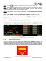
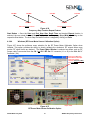
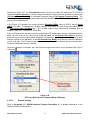
1
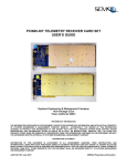
TSS200A TELEMETRY SIGNAL SIMULATOR
USER’S GUIDE
Systems Engineering & Management Company
1430 Vantage Court
Vista, California 92081
PROPRIETARY INFORMATION
THE INFORMATION CONTAINED IN THIS DOCUMENT CONSTITUTES PROPRIETARY INFORMATION AND INTELLECTUAL PROPERTY
OF SYSTEMS ENGINEERING & MANAGEMENT COMPANY (SEMCO). ACCORDINGLY, THE USER(S) OF THIS INFORMATION
AGREE(S) TO PROTECT THIS INFORMATION TO THE EXTENT THAT THEY WILL PREVENT OTHERS FROM COPYING AND/OR
REPRODUCING THIS INFORMATION, EITHER IN WHOLE OR IN PART, OR MANUFACTURE, PRODUCE, SELL OR LEASE ANY
PRODUCT COPIED FROM OR ESSENTIALLY REPRODUCED FROM THE INFORMATION CONTAINED IN THIS DOCUMENT WITHOUT
THE EXPRESSED WRITTEN APPROVAL OF SYSTEMS ENGINEERING & MANAGEMENT COMPANY.
DISTRIBUTION STATEMENT
DISTRIBUTION OF THIS DOCUMENT IS AUTHORIZED TO U.S. GOVERNMENT AGENCIES, THEIR CONTRACTORS, AND
INTERNATIONAL USERS WHO HAVE PURCHASED SEMCO’S TSS200A TELEMETRY SIGNAL SIMULATOR UNDER U.S. EXPORT
RULES AND REGULATIONS. THIS PUBLICATION IS PROVIDED AND REQUIRED SOLELY FOR THE USE AND OPERATION OF THE
TSS200A TELEMETRY SIGNAL SIMULATOR. OTHER REQUESTS FOR THIS DOCUMENT SHALL BE REFERRED DIRECTLY TO
SYSTEMS ENGINEERING AND MANAGEMENT COMPANY
A2522-003/01 July 2012
SEMCO Proprietary Information
SAFETY SUMMARY
System Weight and Handling Restrictions - Depending upon the specific system and configuration,
each TSS200A chassis weighs between 25 and 35 pounds. Accordingly, take care in the lifting and
installation of each chassis. When lifting the chassis, always lift from the bottom of the main chassis
frame.
Electrical – The TSS200A is designed to operate on 115/230 VAC 50/60 Hz, and comply with all U.S.
and International safety codes and regulations required for safe operation and use of commercial
equipment. Use standard and accepted safety practices with respect to operating commercial electrical
equipment at all times to avoid the risk of personal injury or death.
EMI/EMC – The TSS200A complies with all FCC and CE regulations regarding electromagnetic
interference and compatibility. There are no personnel hazards or safety issues with respect to
EMI/EMC when operating the system.
Exposure to Radio Frequency (RF) Signals – The TSS200A is designed to transmit RF signals from
70 MHz to 5250 MHz at levels of +10 dBm to -100 dBm. These signal levels are well below the minimum
safe exposure levels prescribed by both U.S. and International standards.
A2522-003/01 July 2012
SEMCO Proprietary Information
LIST OF EFFECTIVE PAGES
Page
Change
Date
All
A2522-001
02/01/2011
All
A2522-002
06/01/2011
All
A2522-003
07/01/2012
Page
Change
Date
Note:
This Document applies to the TSS200A with SGCMS v4.0.0 or higher
Local Software installed, and system networks that have SGCMS
v4.0.0 or higher Remote Software installed.
This Document also applies to the TSS200A with 4.3” Touch Screen
v1.0.0 and higher software installed.
The latest revision levels of all released software (SGCMS Local,
SGCMS Remote and 4.3” Touch Screen) are available on SEMCO’s
website (www.semco.com) and can be downloaded, installed and
used on all TSS200A systems, regardless of system S/N. Instructions
for downloading and installing this software are on the website as
well as in this User’s Manual.
A2522-003/01 July 2012
SEMCO Proprietary Information
TABLE OF CONTENTS
SECTION
TITLE
PAGE
1
1.1
1.2
INTRODUCTION
Scope
Purpose and Description
1
1
1
2
2.1
2.1.1
2.2
2.3
2.3.1
2.3.2
2.3.3
2.3.4
2.3.5
2.3.5.1
GETTING STARTED
System Description
System Configuration and Options
System Hardware Installation and Set-up
System Software Installation
Software Overview
Software Installation and Boot Procedures
System Shutdown
SGCMS Program Installation
Touch Screen Software Installation
Touch Screen
2
2
2
3
4
4
4
6
7
8
8
3
3.1
3.2
3.2.1
3.2.2
HARDWARE I/O AND SOFTWARE CONTROLS
Simulator Hardware I/O and Operation
SGCMS Network Program Description
SGCMS Local (Client) Program
SGCMS Remote PC (Server) Program
12
12
13
13
14
4
4.1
4.2
4.2.1
4.2.2
4.2.3
4.2.4
4.2.5
4.2.6
4.2.6.1
4.2.6.2
4.2.6.3
4.2.6.4
4.2.6.5
4.2.6.6
4.2.6.7
4.2.6.8
4.2.6.9
4.2.6.10
4.2.6.11
TELEMTRY SIGNAL SIMULATOR OPERATION
Overview
Telemetry Signal Simulator Software Control Panel
RF Control Panel
Modulation Control Panel
Bit Synchronizer Control Panel
Bit Error Rate (BER) Control Panel
Fader Control Panel
Toolbar Settings
Presets (Saving a Preset)
Presets (Loading a Preset)
System Config (Naming Options)
System Config (One Touch Presets Configuration)
Accessing One Touch Presets from the Touch Screen
System Config (Calibration)
Windows (System Configuration)
Windows (Step Function)
Windows (RF Power Meter Sensor Calibration Option)
Network Settings
Help
16
16
16
17
20
25
27
29
29
29
30
31
31
33
33
34
34
36
37
38
A2522-003/01 July 2012
i
SEMCO Proprietary Information
ILLUSTRATIONS
FIGURE
TITLE
PAGE
1-1
TSS200A Telemetry Signal Simulator
1
2-1
2-2
2-3
2-4
2-5
2-6
2-7
2-8
2-9
2-10
2-11
2-12
TSS200A System Power and Boot-Up Connections
System Local and Remote Control Connections
Touch Screen Display
SGCMS GUI Control Panel
System Configuration Display
Touch Screen System Power Down Sequence
Touch Screen Firmware/Software Installation Screen
Touch Screen Firmware Installation Status Screen
Touch Screen Software Installation Sequence
Touch Screen Software Location
Touch Screen Boot-up Display
Touch Screen Main Menu Display
3
3
4
5
5
6
8
9
9
10
10
11
3-1
3-2
3-3
3-4
3-5
TSS200A System I/O Interface
Local (Client) Network Settings and Server Address Set-up
Remote PC (Server) Status Panel
Selecting a TSS200A Control Panel from the Control Window
Selecting a TSS200A Control Panel from the Client’s List
12
13
14
14
15
4-1
4-2
4-3
Software Control Panel and Touch Screen Display
RF Control Panel
Frequency band Display and Frequency Incremental Tuning
Feature
User-Selectable Incremental dBm Level Feature
Touch Screen RF Control Panel
Output Modes
70 MHz Source
Modulation Control Panel
Modulation Mode Menu
Modulation Source Selection
File Playback Feature (with File loaded)
File Playback Feature (File running)
File Playback Feature (no File loaded or selected)
Deviation Indicator
Bit Synchronizer Software Control and Status Panel
Bit Synchronizer Source Selection
Bit Synchronizer Source Type Selection
Bit Synchronizer Data Polarity Selection
Bit Synchronizer Input Code Selection
Bit Synchronizer Output Code Selection
Bit Synchronizer Data Pattern Selection
BER Control and Status Panel
BER Test Conditions
Fader Control Panel
16
17
4-4
4-5
4-6
4-7
4-8
4-9
4-10
4-11
4-12
4-13
4-14
4-15
4-16
4-17
4-18
4-19
4-20
4-21
4-22
4-23
4-24
A2522-003/01 July 2012
ii
18
18
19
19
20
21
21
22
23
23
24
24
25
25
26
26
26
27
27
27
28
29
SEMCO Proprietary Information
ILLUSTRATIONS (continued)
FIGURE
4-25
4-26
4-27
4-28
4-29
4-30
4-31
4-32
4-33
4-34
4-35
4-36
4-37
4-38
4-39
TITLE
PAGE
Toolbar Selections
Saving a Preset
Loading a Preset
Naming Options Feature
One Touch Presets Configuration Feature
Setting Up the One Touch Presets Feature
Accessing One Touch Presets Feature from the Touch Screen
On-Screen TSS200A Calibration Feature
System Configuration Feature
Step Function Feature
dBm Step Function Repeat Feature
Frequency Step Function Repeat Feature
RF Power Meter Sensor Calibration Option
RF Power Meter Sensor Frequency Band Calibration
Toolbar Help Feature
38
29
30
30
31
31
32
33
33
34
34
35
36
36
37
TABLES
TABLE
TITLE
PAGE
3-1
TSS200A Rear Panel Signal I/O
12
4-1
4-2
External Modulation Source Requirements
External Modulation TTL Signal Level and Impedance
22
22
A2522-003/01 July 2012
iii
SEMCO Proprietary Information
1 - INTRODUCTION
1.1
Scope
This User’s Guide provides the necessary information for the installation and operation of SEMCO’s
TSS200A Telemetry Signal Simulator, which is used to test telemetry simulators and telemetry ground
stations by dynamically simulating telemetry signals normally encountered from dual element tracking
antennas during the test of aircraft, missiles and weapon systems.
1.2
Purpose and Description
This User’s Guide provides detailed information to allow for installation and operation of the TSS200A
Telemetry Signal Simulator (Figure 1-1). This Guide addresses all TSS200A systems produced by
SEMCO after the date of this document. This Guide can also be used as reference material for earlier
production systems, even though these earlier system configurations do not have all of the latest
features available with the latest system configurations.
Section 2, Getting Started briefly describes and lists the standard and optional hardware features of the
TSS200A system and then describes how to install and apply power to the TSS200A hardware. Section
2 also describes the initial installation and boot process for the Signal Generator Control and Monitor
Software (SGCMS) program and related Touch Screen software.
Section 3, Hardware I/O and Software Controls describes system hardware I/O interface and provides
instructions for setting up system operation and control. The standardized hardware I/O description
facilitates installation of each TSS200A Telemetry Signal Simulator in a typical Telemetry Ground
Station.
Section 4, Telemetry Signal Simulator Operation provides instructions for TSS200A operations,
including set-up and status monitoring of all simulator operating features and parameters.
Figure 1-1
TSS200A Telemetry Signal Simulator
A2522-003/01 July 2012
1
SEMCO Proprietary Information
2 – GETTING STARTED
2.1
System Description
The TSS200A Telemetry Signal Simulator is a 2U rack-mounted system designed for pre-mission
checkout of a telemetry ground station, as well as telemetry simulator calibration and maintenance
testing. The simulator provides an internally generated pseudo-random PCM code generator, userselectable multi-mode modulator, calibrated single and dual RF outputs, an embedded Bit Synchronizer
and a Bit Error Rate Tester (BERT). The RF output frequency range is 200-1150 MHz, 1415-1585 MHz,
1650-1850 MHz, 2185-2485 MHz and 4400-5250 MHz. Modulation formats include PCM/FM, NTSC
Composite Video, PM, BPSK, QPSK, IRIG 106-09 Tier I SOQPSK-TG and Tier II Multi-h CPM.
The TSS200A can be externally modulated with a user-provided signal and test pattern, and also has
binary file playback capability for external modulation using pre-recorded mission data.
Dynamic combiner performance testing can be accomplished using the combiner fade circuitry which
provides for user-selectable phase shifts and CH1/CH2 signal level shifting (fade) at user-selectable fade
rates.
The TSS200A design consists of a dual channel Test Signal Simulator/Fader, FPGA-based I/Q
modulator an internal 10 MHz reference, an embedded Bit Synchronizer/BERT that includes a pseudorandom code generator, and an internal power meter sensor for providing precise, calibrated RF outputs
within +/- 0.1 dBm. These components are all housed in a ruggedized 2U PC chassis. The Test Signal
Simulator provides a phase-locked RF source and modulator with user-selectable, calibrated RF signal
outputs from +10 dBm to -100 dBm in 0.1 dB increments.
TSS200A system set-up, control and statusing is provided by both a local PC interface and SGCMS GUI
(PC display keyboard and mouse/trackball) and a front panel Touch Screen. Both Local and Remote
operation via Ethernet using the SGCMS Network Software is also provided.
2.1.1
System Configurations and Options
The TSS200A is produced in several user-specified configurations. Standard hardware features include:
a)
b)
c)
d)
e)
f)
g)
Single Band RF Tuning (2185-2485 MHz)
PCM/FM modulation
External modulation
File playback
Embedded Bit Synchronizer and BERT
Front Panel Touch Screen controls and status displays
Removable 32 GB solid state drive
Optional features include:
a)
b)
c)
d)
e)
Multi-band tuning bands spanning 200 MHz to 5250 MHz
Dynamic Combiner Test (fade, phase and fade rate)
Multi-mode demodulation (PM, BPSK, QPSK, IRIG 106-09 Tier I SOQPSK-TG and Tier II
Multi-h CPM)
Composite NTSC Video modulation
Embedded power meter sensor for precision RF outputs
A2522-003/01 July 2012
2
SEMCO Proprietary Information
2.2
System Hardware Installation and Set-up
The user should read this User’s Guide and become familiar and comfortable with the overall features,
options and configuration of the specific system that will be installed and operated.
Ensure safe system installation for operation (i.e., secured in the equipment rack or safely positioned on
a non-slip work surface that can support the system size and weight). Figure 2-1 illustrates the front and
rear panel I/O of all system configurations with respect to AC power, software communications, display,
keyboard and mouse. A jumper cable is installed where shown between the “Translator In” and
“COM 1” connectors in order to operate properly.
Translator In
Jumper to COM 1
Video
AC Power
KB/Mouse
Ethernet
Figure 2-1
TSS200A System Power and Boot-Up Connections
Figure 2-2 depicts the proper system set-up for initializing the system software for both local control and
remote control via Ethernet. (Initializing the system via the Touch Screen does not require this set-up).
Display
Video
Keyboard
Keyboard
Mouse
TSS200A
Mouse
Ethernet
Remote PC
Translator In
Com 1
AC Power
Figure 2-2
System Local and Remote Control Connections
A2522-003/01 July 2012
3
SEMCO Proprietary Information
2.3
System Software Installation
2.3.1
Software Overview
The TSS200A uses the Signal Generator Control and Monitor Software (SGCMS) program and related
Touch Screen software. The SGCMS provides a Graphical User Interface (GUI) for all user-required
control and status monitoring of system operation. The SGCMS runs on a Windows-Based Operating
System (Windows XP), and is designed for local operation using a front panel Touch Screen, a display
and keyboard/mouse, and/or remotely controlled via RS-232 or Ethernet.
This document addresses the SGCMS Local software v4.0.0 and higher program, SGCMS Remote
software V4.0.0 and higher program, and the 4.3” Touch Screen software v1.0.0 and higher program. All
system functions and set-up controls are by keyboard entry and/or by pull-down menu screens selected
and controlled by the mouse/touchpad, or via the Touch Screen on specific systems with this feature.
System status is via display indicators (alpha-numerical readouts) on both a PC display and the system
Touch Screen.
2.3.2
Software Installation and Boot Procedures
Once AC power is applied to the system chassis, start the Windows XP Operating System as well as the
SGCMS program by depressing the ON/OFF button located on the front panel.
Clicking on the Antenna icon in the Start-Up Menu or Desktop will also initiate system software.
During the “auto-boot” process, “Obtaining System Settings…..” and a numerical countdown window is
displayed. The first countdown is the commands being sent to all installed cards to determine what
system configuration is installed (i.e., what cards are installed). The second countdown is all the system
settings. The system automatically retrieves and displays all system settings from the last system set-up.
The SGCMS “auto-boot” process enables the front panel Touch Screen (Figure 2-3).” The corresponding
local GUI display is shown in Figure 2-4.
Figure 2-3
Touch Screen Display
A2522-003/01 July 2012
4
SEMCO Proprietary Information
Figure 2-4
SGCMS GUI Control Panel
Once the applicable GUI control panels appear on the display and Touch Screen, the next step is to click
on “Windows” and then “System Configuration” (Figure 2-5). The System Configuration display
provides important information to ascertain initial system health and communication status, as well as
determine the exact system Circuit Card Assembly (CCA) and software/firmware configuration.
Figure 2-5
System Configuration Display
A2522-003/01 July 2012
5
SEMCO Proprietary Information
2.3.3
System Shutdown
There are 3 methods to Shutdown a system:
A.
Standard Windows shutdown through the Windows Operating System
Step 1 - Press Start on the GUI Desktop
Step 2 - Select Shutdown
Step 3 - Select Shutdown from the resulting pop-up window to shut down the system.
B.
Shutdown Sequence using the system Touch Screen (Figure 2-6)
Step 1 - Press Utility from the top level menu
Step 2 - Press red SHUTDOWN button in top right corner
Step 3 - Select YES to commit to shutting down the simulator
Step 2
Step 1
Step 3
Figure 2-6
Touch Screen System Power Down Sequence
C.
Physical shutdown by a SINGLE ONE (1) SECOND PRESS of the power button on the system
front panel of the simulator.
A2522-003/01 July 2012
6
SEMCO Proprietary Information
NOTE:
This method is only valid for momentary (Green) power switches.
Latching On/Off (Red) power switches will shut off power to the
chassis without executing a clean system shutdown as described in
previous steps.
CAUTION
The methods described above should be used in all circumstances
unless absolutely unavoidable. Physically removing power from the
chassis by means of cutting AC power to the chassis or holding the
power button down for a hard shutdown is not recommended.
If the operating system is in the middle of a write cycle, a hard
shutdown could cause file corruption resulting in faulty operation or
inability to boot the system.
2.3.4
SGCMS Program Installation
A.
Using a CD provided by the factory.
Step 1 - To install a new or updated SGCMS program, click the GUI Desktop “Start”, “Control Panel”,
“Add or Delete Programs” and then uninstall the “SEMCO SGCMS” program on the simulator.
Step 2 – Go to C:\Program Files\SEMCO and then delete all files within the program folder (“SEMCO
SGCMS” or “SEMCO SGCMS Server”) on the simulator, except for the .pdf User’s Manual. Alternatively,
copy the User’s Manual to another hard drive location, delete the program folder and copy the PDF
manual back into the program folder after the new SGCMS program is installed in Step 3.
Step 3 – Connect an external USB-CD drive to the TSS. If an external USB-CD drive is not available,
then the SGCMS program can be installed using a commercially-available USB Thumb drive and one of
the system’s USB ports. The files located on the CD must be transferred to the USB Thumb Drive.
Another alternative is to access the installation files on a network through the Ethernet port.
Step 4 – Install the SGCMS program on the simulator by executing the Setup.exe program file on the CD
(USB drive, Network) and follow the instructions appearing on the monitor display.
B.
Downloading and Installing SGCMS Software from the SEMCO website.
Step 1 – If the TSS Simulator has internet access, go to the www.semco.com homepage and select
TECHNICAL and then PRODUCT SOFTWARE. Select and download the software to the hard drive.
Proceed to Step 3.
If using an internet capable PC, go to the www.semco.com homepage and select TECHNICAL and then
PRODUCT SOFTWARE. Select and download the software to the hard drive. Alternatively, download
the software to a USB Flash Drive, if Flash Drives are authorized at the Telemetry Simulator Installation
site.
A2522-003/01 July 2012
7
SEMCO Proprietary Information
Step 2 - Using an installed Read-Write CD drive or commercially-available USB-compatible external CD
drive connected to one of the PC USB ports; burn the downloaded software program(s) to a new CD. A
USB Flash Drive can also be used if authorized at the Telemetry Simulator Installation site.
Step 3 – Follow section A., Steps 1 thru 4 above.
2.3.5
Touch Screen Software Installation
2.3.5.1
Touch Screen
Step 1 – Download the latest 4.3” Touch Screen software from the www.semco.com website (see
paragraph 2.3.4 B.). Extract the LCD folder from the downloaded “zip” file and replace the “C:\LCD”
folder located on the hard drive of the simulator.
Step 2 - First make sure the SEMCO SGCMS GUI is completely closed.
Step 3 - The program that is used for installation of new or updated Touch Screen firmware and software
is available on the hard drive of each simulator system in C:\LCD\BMPloadxxxx.exe. Execute the
BMPload program. The program will open with the window shown in Figure 2-7. Please make sure the
text “BMPload Vx.x.x Supports SLCD43” is displayed in the blue bar of the program as shown. Contact
the factory if the text is different.
Step 4 - Ensure that the latest firmware is installed in the Touch Screen. Contact the factory for a CD
with the latest 4.3” Touch Screen firmware, or go to www.semco.com home page to check and, if
necessary download the latest firmware version.
Step 3
Step 6
Step 5
Step 4
Step 7
Figure 2-7
Touch Screen Firmware/Software Installation Screen
A2522-003/01 July 2012
8
SEMCO Proprietary Information
Step 5 - Click on the “Add Firmware” button. A window will pop up for navigating to the location of the
firmware upgrade file (i.e. Hard Drive, Flash Drive or CD).
Step 6 - Set the Port Settings as shown in Figure 2-7. Select the COM3 Port and a 460800 Baud Rate.
Select USB Autobaud and press Connect. If an error appears try 115,200 Baud Rate.
Step 7 - If the connection is successful, click on the button “Store into SLCD”. When programming is
complete, the SLCD Status screen will appear as shown in Figure 2-8.
Figure 2-8
Touch Screen Firmware Installation Status Screen
Step 8 - After new firmware is loaded into the Touch Screen, all parameters including the Baud rate are
reset. The baud rate should now be 115,200. If the baud rate has not automatically changed to 115,200,
change it to that rate as shown in Figure 2-9.
Step 8
Step 10
Step 11
Step 12
Figure 2-9
Touch Screen Software Installation Sequence
A2522-003/01 July 2012
9
SEMCO Proprietary Information
Step 9 – The latest 4.3” Touch Screen software file, which was downloaded in Step 1, is shown in Figure
2-10. Alternatively, contact the factory to obtain a copy of the latest software version. This software
program name will always end in .BIN.
Select .BIN file
for download
Figure 2-10
Touch Screen Software Location
Step 10 – Referring again to Figure 2-9, click on “Load from File” and a pop-up window will appear.
Navigate to the location of the .BIN file, select the file and press Open.
Step 11 - Make sure the following boxes are selected (checked); Set Power On Macro, Enable Bitmap
Compression, Power On Macro = 1 and High Color.
Step 12 - Click on “Store into SLCD” and wait until the “SLCD Status” completes (see Figure 2-9).
Step 13 – Power down the simulator system. This action allows the Touch Screen to reset itself with the
new programming. Restart the system. As soon as the computer starts booting, the Touch Screen
display will appear as shown in Figure 2-11.
Figure 2-11
Touch Screen Boot-up Display
A2522-003/01 July 2012
10
SEMCO Proprietary Information
At this point, verify that the latest SGCMS Local Software has been installed, and refer to paragraph
2.3.4 if the SGCMS Software needs to be installed. When the GUI completes its startup, the Touch
Screen will be functional, and the Touch Screen Main Menu screen appears as shown in Figure 2-12.
Figure 2-12
Touch Screen Main Menu Display
A2522-003/01 July 2012
11
SEMCO Proprietary Information
3 – HARDWARE I/O AND SOFTWARE CONTROLS
3.1
Simulator Hardware I/O and Operation
Figure 3-1 depicts the TSS200A front and rear panel I/O. The front panel consists of a POWER ON/OFF
and POWER/RESET indicator, 2 USB ports, a 4.3” Touch Screen and a lockable door assembly housing
a removable Solid State Drive (SSD). Table 3-1 lists and describes the TSS200A rear panel I/O
interface.
Video
AC Power
KB/Mouse
RS485 Translator-to-COM Port Jumper Cable
Signal I/O
Ethernet
Figure 3-1
TSS200A System I/O Interface
Table 3-1
TSS200A Rear Panel Signal I/O
Ref. Des.
J1
J2
J3
J4
J5
J6
J7
J8
J9
J10
J11
J12
J13
J14
Input/Output
CH 1 RF Out
CH 2 RF Out
PCM Out
70 MHz Out
Data In 2
Data In 1
Sync
I Data In
Data Out
Q Data In
CLK Out
70 MHz In
AUX 1
CAL In
A2522-003/01 July 2012
Description
“N” Connector RF Output (Channel 1)
“N” Connector RF Output (Channel 2)
Not Used
BNC 70 MHz Output Signal (Modulated)
BNC Channel 2 Data Input (from TM Simulator Baseband Video)
BNC Channel 1 Data Input (from TM Simulator Baseband Video)
Not Used
BNC External TTL Modulation Data Input
BNC Bit Synchronizer Data Output
BNC External TTL Modulation Data Input
BNC Bit Synchronizer Clock Output
BNC Input for external 70 MHz Modulation Source
BNC Auxiliary I/O reserved for future requirements
“N” Connector input used for optional precision RF output calibration
12
SEMCO Proprietary Information
3.2
SGCMS Network Program Description
SEMCO’s SGCMS Network Program provides for remote control of one or several TSS200A systems.
The Network Software comes in two separate applications. The Remote PC (“Server”) side uses the
SGCMS Server Program, and the Local TSS200A (“Client”) side uses the SGCMS Client Program.
The SGCMS Client program is installed on each individual TSS200A system. This program allows for
local monitoring and control of the TSS200A via a display and keyboard/mouse. In addition, each Local
TSS200A (Client system) will attempt to connect to the SGCMS Remote PC (Server application) at a
specified Server IP address that has been set in the SGCMS Client application.
The SGCMS Server application resides on one remote PC (the “Server”) and, once activated, listens for
any Client systems requesting connection to it. A connection is established when a Client’s request is
detected, and a graphical status panel is displayed in the Server system’s main window.
3.2.1
SGCMS Local (Client) Program
Figure 3-2 depicts a single channel simulator control panel with the SGCMS Client Program installed. To
set up the TSS200A in a network, the user selects “Network Settings” on the Toolbar as shown in
Figure 3-2, and then proceeds with the following steps:
Step 1 - The user then verifies that the IP address that is displayed in the “Server Address” window is
the correct IP address for the Remote PC (Server). If so, then the user simply clicks on “Reset
Connection”, and the Client simulator is activated for network operation.
Step 2 - If the Remote PC (Server) Address is different, then the user clicks on the “IP Address” window
(i.e., “192.168.1.209” as depicted in Figure 3-2), and the “Server Address Setup” window appears as
shown.
Step 3 - The user then types in the correct Remote PC (Server) IP address in the “New Address”
window, clicks “OK” and then “Reset Connection” to activate the Client simulator for network operation.
The user then installs the Client SGCMS on each simulator system that will be networked and repeats
steps 1 through 3 for each TSS200A system that is connected to the network.
Blue Antenna Icon indicates system is networked
Figure 3-2
Local (Client) Network Settings and Server Address Set-up
A2522-003/01 July 2012
13
SEMCO Proprietary Information
3.2.2
SGCMS Remote PC (Server) Program
The user installs the Remote PC (Server) SGCMS Program on the server PC and
this icon appears on the server desktop. Clicking on this icon opens the program
and displays status panels of all system clients (TSS200A systems) that are on
the network. Figure 3-3 is an example of a networked TSS200A system.
Blue Antenna Icon
indicates system is
networked
Figure 3-3
Remote PC (Server) Status Panel
To control a Local (Client) system remotely, the user right clicks anywhere on the status panel of the
desired system and then clicks on the “Control” window. As shown in Figure 3-4, clicking on the
“Control” window opens up the control panel of the TSS200A selected, and the system settings can be
changed as desired. This control panel is identical to the local control panel of the selected Local (Client)
TSS200A. Any changes made at either the Local (Client) control panel or Remote PC (Server) control
panel is activated on both panels.
An alternative method for selecting a system control panel is shown in Figure 3-5. By clicking on
“Clients” in the Toolbar, the user can click on any client TSS200A and open its respective control panel.
Figure 3-4
Selecting a TSS200A Control Panel from the Control Window
A2522-003/01 July 2012
14
SEMCO Proprietary Information
Figure 3-5
Selecting a TSS200A Control Panel from the Clients List
A2522-003/01 July 2012
15
SEMCO Proprietary Information
4 – TELEMETRY SIGNAL SIMULATOR OPERATION
4.1
Overview
This section describes all steps and features required for Telemetry Signal Simulator operation. The
Graphical User Interface (GUI) and front panel Touch Screen described herein is for all delivered
TSS200A systems.
The TSS200A is designed for local operation using its internal PC (Single Board Computer), or remote
operation via Ethernet. The TSS200A Signal Generator Control and Monitor Software (SGCMS)
program, as further described in this section is hosted on a Windows XP Operating System that is
installed on each Local (Client) simulator system. The SGMS Remote PC (Server) software program is
installed on a remote PC (Server) running Window XP and connected to the TSS200A via Ethernet.
Using the SGCMS program, all system functions and set-up are controlled by keyboard entry and/or by
pull-down menu screens on the GUI display that are selected and controlled by the mouse. System
status is provided via display indications (numerical readouts and bar graphs).
All of these GUI controls and displays are also available via the 4.3” Touch Screen on the TSS200A front
panel. SGCMS program GUI control panels, sub-panels and correlating Touch Screen controls are
described in subsequent paragraphs.
4.2
Telemetry Signal Simulator Software Control Panel
Figure 4-1 depicts the Test Simulator Software Control Panel and corresponding front panel Touch
Screen display. The TSS200A software control panel (and Touch Screen) is divided into the following
sub-panels:
A.
C.
D.
RF
Modulation
Internal Data
B.
D.
F.
Fader
Bit Sync
BER
Each of these functions is described in the following paragraphs.
Figure 4-1
Software Control Panel and Touch Screen Display
A2522-003/01 July 2012
16
SEMCO Proprietary Information
4.2.1 RF Control Panel
The RF Control panel (Figure 4-2) is used to select the Output Frequency (Frequency (MHz)), and
provides status (Synth) indicating whether or not the Simulator output channel is tuned to the frequency
of interest. A GREEN LOCK Synth means that the RF outputs are tuned to the frequency entered in the
Frequency (MHz) box. The Synth indicator is also used to determine health and status monitoring of the
Simulator channel. A constant RED NO COMM (never GREEN) Synth indication means user control and
status monitoring is not available or working, and indicates a malfunction in the internal TSS200A
PC/Simulator communication link. A RED UNLOCKED Synth after a valid frequency has been entered
(i.e., was GREEN LOCK before frequency entry) indicates a TSS200A hardware malfunction.
Frequency (MHz) - The RF Output Frequency can be either typed in, or selected by scrolling in 100 kHz
increments using the up-down arrow (▲▼) icons located on the right of the frequency indicator box. The
system will only accept valid frequencies of the particular frequency bands installed in the Simulator.
The entire frequency (for example: 2335.0) must be typed in. The system will tune and output an RF
signal at that frequency as long as the Synth indicator remains a GREEN LOCK.
Once the user has typed in the frequency of interest, the user then hits “ENTER” and the Frequency
(MHz) window turns gray, indicating that the frequency has been accepted and tuned.
Right-clicking on the Frequency (MHz) provides a display of all frequency bands installed in a given
TSS200A. Right-clicking on the actual frequency displayed in the Frequency (MHz) window provides
user-selectable RF frequency tuning increments of 0.1, 1.0, 10.0 and 100.0 MHz steps. Figure 4-3
illustrates these features.
Figure 4-2
RF Control Panel
A2522-003/01 July 2012
17
SEMCO Proprietary Information
Right-Clicking on
Frequency (MHz)
displays installed
Frequency Bands
Right-Clicking on
1750.0 displays userselectable frequency
tuning increments
Figure 4-3
Frequency Band Display and Frequency Incremental Tuning Feature
Level (dBm) – Referring again to Figure 4-2, The RF Output level can be either typed (entered) from
+10 dBm to -100 dBm in 0.1 dB increments, or selected by scrolling in 0.1 dB increments using the updown arrow (▲▼) icons located on the right of the Level (dBm) box.
Right clicking on the Level (dBm) window allows the user to change the increments to either 0.1 dB, 1
dB or 10 dB (Figure 4-4).
Right-Clicking on the
0.0 displays userselectable dBm Level
Tuning increments
Figure 4-4
User-Selectable Incremental dBm Level Feature
The corresponding Touch Screen FREQ (MHz) and Synth indicator is shown in Figure 4-5. Touching
the FREQ (MHz) window produces the keyboard for frequency entry as shown.
The RF Output level can also be changed via the Touch Screen (Figure 4-5) by touching the LEVEL
(dB) window or the Up/Dn arrows.
Level increments can be changed to 0.1 dB, 1.0 dB or 10.0 dB by touching the Units window as shown
in Figure 4-5.
A2522-003/01 July 2012
18
SEMCO Proprietary Information
Touching the LEVEL (dB) window (e.g. -50.0 or
Up/Down arrows) changes the RF output level.
Touching the Units window changes the LEVEL (dB)
increments to 0.1, 1.0 or 10.0 dB
Touching the FREQ (MHz) window (e.g. 2335.0)
displays the keypad for frequency entry (a new
frequency of 2250.5M is shown, but not yet entered).
Figure 4-5
Touch Screen RF Control Panel
Outputs – Figure 4-6 depicts the GUI pull-down window and Touch Screen control that allows the user
to select CH1, CH2 or both (COMB) RF Outputs. The user can also turn the RF Outputs off (OFF).
Clicking on the GUI
Outputs window
displays pull-down
menu
Touching the
Touch Screen
OUTPUT box
changes the RF
Output mode
Figure 4-6
Output Modes
A2522-003/01 July 2012
19
SEMCO Proprietary Information
70 MHz Source – Figure 4-7 depicts the GUI pull-down menu and Touch Screen control that allows the
user to select either the internal 70 MHz modulation source (Internal), or an external 70 MHz modulation
source (External).
Clicking on the GUI 70
MHz Source window
displays pull-down
menu (External or
Internal)
Touching the Touch Screen 70 MHz Ref box changes the 70
MHz modulation source (Internal or External)
Figure 4-7
70 MHz Source
4.2.2
Modulation Control Panel
The Modulation Control panel (Figure 4-8) is used to select modulation format (Mode), and the
modulation data source (Data Source).
Mode – This pull-down menu (Figure 4-9) allows the user to select the desired modulation mode by
clicking on the arrow (▼) icon to the right of the Modulation Mode box. Touching the Mode box on the
Touch Screen provides this same selection. Available modulation modes include PCM/FM, PCM/PM,
BPSK, QPSK, Tier I SOQPSK-TG, Tier II Multi-h CPM and NTSC Video.
Source – Figure 4-10 shows a pull-down menu that allows the user to select the desired modulation
source by clicking on the arrow (▼) icon to the right of the Modulation Data Source box. The user then
clicks on either no modulation (None), the internal modulation source (Internal), a binary playback file
(File Plybck) or an external modulation source (External). Touching the Source box on the Touch
Screen provides these same selections as shown.
A2522-003/01 July 2012
20
SEMCO Proprietary Information
When External is selected, the user provides an external TTL modulation input to the I and Q Input BNC
connectors on the rear panel as defined in Tables 4-1 and 4-2.
Figure 4-8
Modulation Control Panel
Touching the Touch
Screen Mode box selects
the available modulation
modes
Clicking on the GUI
Mode window (▼)
displays Modulation
Mode pull-down menu
Figure 4-9
Modulation Mode Menu
A2522-003/01 July 2012
21
SEMCO Proprietary Information
s
Clicking on the GUI Data
Source window (▼)
displays data source
pull-down menu
Touching the Touch
Screen Source box selects
the available data source
modes
Figure 4-10
Modulation Source Selection
Table 4-1
External Modulation Source Requirements
Mode Back Panel J8
EXT. DATA IN / I DATA IN
FM, PM, BPSK
Digital (TTL) Data
QPSK
Digital (TTL) Data I
SOQPSK, CPM
*Digital (TTL) Data
*Data is latched on falling edge of Digital Clock.
Back Panel J10
EXT. CLOCK IN / Q DATA IN
Not Used
Digital (TTL) Data Q
Digital (TTL)Clock
Table 4-2
External Modulation TTL Signal Level and Impedance
Input Logic
VIH
VOH
Minimum Signal Level
1.7 V
Maximum Signal Level
0.7 V
Impedance
75 ohms
75 ohms
File Playback – Figure 4-11 illustrates the File Playback (File Plybck) mode on both the GUI and Touch
Screen. The File Playback mode allows the user to load a binary file (usually recorded mission data) on
the TSS200A Solid State Drive (SSD), and then be able to select and run this file as the data source for
modulating the TSS200A RF output.
The user can load the binary file of interest either via the TSS200A USB port(s), or access the SSD with
a remote PC via Ethernet when running SCGMS Network software. Figure 4-11 depicts the GUI and
Touch Screen controls when a file has been loaded on the SSD and is available to select and play back
(the example file is “pn15”).
As shown in Figure 4-12, the user then selects and runs the file from either the GUI or Touch Screen.
The user has the ability to start and stop the file, or to run the file in a continuous loop.
A2522-003/01 July 2012
22
SEMCO Proprietary Information
Clicking on the GUI Data
Source window (▼) and
selecting File Plybck
displays the File
Playback window as
shown
Touching the Touch
Screen Playback box
selects the FILE
PLAYBACK MENU
Figure 4-11
File Playback Feature (with File loaded)
File Loading
Touching the
Touch Screen
Loop File On box
and then START/
STOP box starts
the Loop file run
Playback Start
Playback Stop
Figure 4-12
File Playback Feature (File running)
A2522-003/01 July 2012
23
SEMCO Proprietary Information
Figure 4-13 is the Touch Screen display that is present when PLAYBACK is selected, but no file has
been loaded or selected. The Touch Screen has no Windows navigation capabilities. However, Playback
can be initiated from the Touch Screen after a playback file has been preloaded using the GUI.
Figure 4-13
File Playback Feature (no file loaded or selected)
Deviation Indicator – Figure 4-14 depicts the Deviation display (GUI and Touch Screen), which
provides the modulation index relative to data rate for all phase modulation modes in radians (Rads),
and in Hz (Hz) for the PCM/FM modulation format. The PM deviation can be changed using the up-down
arrow (▲▼) icons located on the right of the Deviation box. Touching the Deviation box on the Touch
Screen opens a keypad for entering the desired deviation. All other modes are relative to data rate.
PCM/FM
A2522-003/01 July 2012
Figure 4-14
Deviation Indicator
24
QPSK
SEMCO Proprietary Information
4.2.3
Bit Synchronizer Control Panel
Figure 4-15 depicts the Bit Synchronizer Control Panel (GUI and Touch Screen). The Status displays a
bit synchronizer OFF, UNLOCK or LOCK status indication. In LOCK condition, the Status indicator can
also be FAST or SLOW, indicating either an over-clocked or under-clocked condition. The Received
Rate (bps) displays the bits per second in 1 x 10-N (E-00N) format. User selectable features include
Source, Source Type, Data Polarity, Input Code, Output Code and Pattern (2^n).
Touching the BS/BER window accesses
the BITSYNC-BER MENU
Figure 4-15
Bit Synchronizer Software Control and Status Panel
Source - Clicking Source provides a pull-down menu (Figure 4-16) for Data Input 1 or Data Input 2 on
the rear panel. Touching the SOURCE window on the Touch Screen BITSYNC-BER MENU selects
either Data Input 1 or 2.
Figure 4-16
Bit Synchronizer Source Selection
A2522-003/01 July 2012
25
SEMCO Proprietary Information
Source Type – Clicking Source Type provides a pull-down menu (Figure 4-17) for selecting either an
Analog or Digital Data source. Touching the TYPE window on the Touch Screen BITSYNC-BER MENU
selects either an Analog or Digital Data source.
Figure 4-17
Bit Synchronizer Source Type Selection
Data Polarity - Clicking Data Polarity provides a pull-down menu (Figure 4-18) for selecting either
Positive (POS) or Negative (NEG). Touching the POLARITY window on the Touch Screen BITSYNCBER MENU selects either Positive or Negative.
Figure 4-18
Bit Synchronizer Data Polarity Selection
Input Code - Clicking Input Code provides a pull-down menu (Figure 4-19) for all user-selectable input
codes. Touching the INPUT CODE window on the Touch Screen BITSYNC-BER MENU provides for all
user-selectable input codes.
Figure 4-19
Bit Synchronizer Input Code Selection
Output Code - Clicking Output Code provides a pull-down menu (Figure 4-20) for all user-selectable
output codes. Touching the OUTPUT CODE window on the Touch Screen BITSYNC-BER MENU
provides for all user-selectable input codes. This Output Code is the code used by the internal
modulator for generating the modulated RF Output(s).
A2522-003/01 July 2012
26
SEMCO Proprietary Information
Figure 4-20
Bit Synchronizer Output Code Selection
Pattern (2^n) - Clicking Pattern (2^n) provides a pull-down menu (Figure 4-21) for all user-selectable
data patterns. Touching the PATTERN window on the Touch Screen BITSYNC-BER MENU provides for
all user-selectable data patterns. This Pattern (2^n) length is used by the internal modulator for the
modulated RF Output(s).
Figure 4-21
Bit Synchronizer Data Pattern Selection
4.2.4
Bit Error Rate (BER) Control Panel
Figure 4-22 depicts the Bit Error Rate (BER) Control Panel (GUI and Touch Screen). Status displays a
BERT OFF, SYNC or LOSS status indication. Seconds displays the BERT test interval in seconds.
Current BER displays the current BER. Errors display the number of bit errors during the test interval.
Clicking on Test Period (or touching Touch Screen PERIOD window) provides a pull-down Test
Period menu (or PERIOD selection) in seconds (1 S, 2 S, 5 S, 10 S, 30 S or 60 S), or accumulated time
(free-running at no fixed interval) by selecting ACC. Clicking on Start/Stop or touching the Touch
Screen START-STOP window starts and stops the BER tests.
Figure 4-22
BER Control and Status Panel
A2522-003/01 July 2012
27
SEMCO Proprietary Information
Figure 4-23 depicts the 3 condition indications (GUI and Touch Screen) that might possibly occur during
BER testing (BER SYNC with no bit errors, BER LOSS indicating no signal present, and BER SYNC with
bit errors)
BER SYNC with No Bit Errors
BER LOSS
BER SYNC with Bit Errors
Figure 4-23
BER Test Conditions
A2522-003/01 July 2012
28
SEMCO Proprietary Information
4.2.5
Fader Control Panel
Figure 4-24 depicts the Fader Control Panel (GUI and Touch Screen). The user selects Depth (dB) to
enter the CH1/CH2 fade depth in dB (0 to 30 dB in 1 dB increments). The user selects Phase (degrees)
to enter the desired phase shift between CH1 and CH2 (0 to 180 degrees in 1 degree increments). The
user selects Rate (Hz) to enter the desired CH1/CH2 fade rate in Hz (1 Hz to 100 kHz). Clicking on the
Fader OFF/ON window turns the Fader OFF or ON. With the Fader ON, the CH1 and CH2 RF Outputs
change in dB amplitude (Depth) and Phase (degrees) at the selected Rate (Hz).
Clicking on this
window turns Fader
ON or OFF
Touching the
OFF/ON button
enables Fader
Figure 4-24
Fader Control Panel
4.2.6
Toolbar Settings
The SGCMS GUI Toolbar (Figure 4-25) allows the user to select a variety of functions and features as
pull-down menus or displays under the headings of “Presets”, “System Config”, “Windows”, “Network
Settings”, ”Configuration” and “Help”.
Figure 4-25
Toolbar Selections
4.2.6.1
Presets (Saving a Preset)
Figure 4-26 depicts the pull-down menu for Presets – Save >System selection. With this selection, the
user can name and save TSS200A setups in the system Solid State Drive.
A2522-003/01 July 2012
29
SEMCO Proprietary Information
As shown in Figure 4-26, clicking on Presets – Save >System directs the user to a directory where the
TSS200A set-ups can be named (Step 1) and saved (Step 2) as a .chs file. The example shown is a
Preset Save for a 4 Mbps PCM/FM setup at 2185 MHz.
Step 1
Step 2
Figure 4-26
Saving a Preset
4.2.6.2
Presets (Loading a Preset)
Once the user has named and saved a Preset as previously described in paragraph 4.2.6.1, this Preset
can be loaded at any time. Figure 4-27 depicts the sequence for loading the 4 Mbps PCM/FM example
previously saved (Figure 4-26).
Step 1
Step 2
Selecting the Saved File (Step 1) and
then opening the file (Step 2) sets the
TSS200A up at all saved settings in
the file
Figure 4-27
Loading a Preset
A2522-003/01 July 2012
30
SEMCO Proprietary Information
4.2.6.3
System Config (Naming Options)
Figure 4-28 depicts the System Config – Naming Options selection on the Toolbar. Selecting this
feature allows the user to type in and save a name for both the System and SigGen 1 GUI displays,
which then appear on the two corresponding blue GUI headers.
Both System Name and SigGen 1
Name can be changed and saved
Figure 4-28
Naming Options Feature
4.2.6.4
System Config (One Touch Presets Configuration)
Figure 4-29 depicts the System Config – One Touch Presets Configuration selection on the Toolbar.
This feature provides for displaying and enabling “Saved” Presets on the GUI display with one click of the
mouse. The user clicks on “System Config” as shown in Figure 4-29, and then uses the “One Touch
Preset Configuration” to bring desired Presets to the GUI Control Panel as shown in Figure 30.
Figure 4-29
One Touch Presets Configuration Feature
A2522-003/01 July 2012
31
SEMCO Proprietary Information
Step 1
Step 2
Step 5
Step 3
Step 4
Figure 4-30
Setting Up the One Touch Presets Feature
Referring to Figure 4-30, the user sets up the One Touch Presets feature as follows:
A2522-003/01 July 2012
32
SEMCO Proprietary Information
Step 1 – Click on
to access the “Complete System Preset” Directory (Figure 4-30).
Step 2 – Select and open the desired Preset to be accessible on the GUI Control Panel. In the Figure 430 example, “PCM FM at 4 Mbps” has been loaded into “Preset #1”. Clicking on “Reset” removes the
loaded preset from the One-Touch Preset Configuration window.
Step 3 - Verify all of the desired Presets are loaded into the “One-Touch Presets Configuration”
window.
Step 4 - Select “Windows” and then “One Touch Presets-Full System” as shown in Figure 4-30.
Step 5 – Figure 4-30 depicts the One-Touch Presets Windows Display on the front panel GUI. The user
can then enable any preset by clicking on the preset desired. “PCM FM at 4 Mbps” is depicted in the
Figure 4-30 example.
4.2.6.5
Accessing One-Touch Presets from the Touch Screen
Once “Presets” have been loaded and saved into the “One-Touch Preset Configuration” (Figure 4-30),
these “Presets” can be accessed via the front panel Touch Screen by touching Presets and then
selecting (touching) the desired Preset # as depicted in Figure 4-31.
Figure 4-31
Accessing One Touch Presets Feature from the Touch Screen
4.2.6.6
System Config (Calibration)
Figure 4-32 shows the window that appears when System Config – Calibration is selected. This
password-protected feature provides access to all on-screen factory calibration procedures, and can only
be accessed by personnel who have been trained and certified as TSS200A maintenance technicians.
Contact the factory if having this capability is essential to operations and maintenance training is desired.
Figure 4-32
On-Screen TSS200A Calibration Feature
A2522-003/01 July 2012
33
SEMCO Proprietary Information
4.2.6.7
Windows (System Configuration)
Selecting “Windows” and then “System Configuration” on the software control panel Toolbar provides
a display as depicted in Figure 4-33. This display indicates what CCAs are installed in the system, what
firmware revision level is installed in each CCA, and the Serial Number of each CCA.
The “System Configuration” window is created by polling each CCA upon start-up and extracting the
displayed information accordingly. This provides an indication of system software communication health
as well as being a source for a status accounting of each system’s hardware and software configuration.
Figure 4-33
System Configuration Feature
4.2.6.8
Windows (Step Function)
Figure 4-34 depicts selection of the Step Function feature.
Figure 4-34
Step Function Feature
A2522-003/01 July 2012
34
SEMCO Proprietary Information
The Step Function feature provides the user with the ability to automatically “step” the RF frequency
and amplitude through selectable ranges. This feature is especially useful in performing pre-mission
“Step-Cals”, where the user steps the input to telemetry receivers while recording the AGC outputs.
Referring to Figure 4-34, the following selections are provided:
Level Step (dBm) - The user can enter a Start dBm level from +5.1 to -100.1 dBm, or set a level using
the up-down arrow (▲▼) icons located on the right of the Start indicator window.
The user can then enter an End dBm level from +5.1 to -100.1 dBm, or set a level using the up-down
arrow (▲▼) icons located on the right of the End indicator window.
The Step Size can be entered from 0.1 dBm to 99.9 dBm, or set using the up-down arrow (▲▼) icons
located on the right of the Step Size indicator window.
Dwell Time (mS) is the time that is programmed for each dBm step level and can be selected from 300
ms to 9999 ms (9.999 sec). The user can type in the desired “step level dwell time”, or set using the updown arrow (▲▼) icons located on the right of the Dwell Time (mS) indicator window.
The Repeat feature is a pull-down menu feature which allows the step function to be a one-time
occurrence by selecting Single (none), or as a repeat Saw Tooth or Triangular pattern. Figure 4-35
shows how this Repeat function works, using a level step range of -10 to -100 dBm as an example.
-10 dBm
-10 dBm
-10 dBm
-100 dBm
-10 dBm
-100 dBm
Saw Tooth Repeat Function
-100 dBm
Triangle Repeat Function
Figure 4-35
dBm Step Function Repeat Feature
Frequency Step (MHz) - The user can enter a Start dBm level from 199.8 MHz to 5150.2 MHz, or set a
level using the up-down arrow (▲▼) icons located on the right of the Start indicator window.
The user can then enter an End dBm level from 199.8 MHz to 5150.2 MHz, or set a level using the updown arrow (▲▼) icons located on the right of the End indicator window.
The Step Size can be entered from 0.1 MHz to 9999.9 MHz, or set using the up-down arrow (▲▼) icons
located on the right of the Step Size indicator window.
Dwell Time (mS) is the time that is programmed for each frequency step level and can be selected from
300 ms to 9999 ms (9.999 sec). The user can type in the desired “frequency level dwell time”, or set
using the up-down arrow (▲▼) icons located on the right of the Dwell Time (mS) indicator window.
The Repeat feature is a pull-down menu feature which allows the step function to be a one-time
occurrence by selecting Single (none), or as a repeat Saw Tooth or Triangular pattern. Figure 4-35
shows how this Repeat function works, using a level step range of 2185 MHz to 2485 MHz as an
example. Figure 4-36 is an example using a level step range of 2185 MHz to 2485 MHz.
A2522-003/01 July 2012
35
SEMCO Proprietary Information
2185 MHz
2185 MHz
2485 MHz
2185 MHz
2185 MHz
2485 MHz
Saw Tooth Repeat Function
2485 MHz
Triangle Repeat Function
Figure 4-36
Frequency Step Function Repeat Feature
Start Button – Once the Start and End, Step Size, Dwell Time and desired Repeat function is
selected, the user starts the Level Step (dBm) and/or the Frequency Step (MHz) by clicking on the
respective Start button. The Auto Step Generator function is stopped by clicking on Close.
4.2.6.9
Windows (RF Power Meter Sensor Calibration Option)
Figure 4-37 shows the pull-down menu selection for the RF Power Meter Calibration Option when
installed. This option provides the ability to closely calibrate the simulator’s RF outputs when more
precise RF signal levels are desired. The Power Meter Window is selected as shown, and an RF
jumper cable is connected from the CH 1 or CH 2 RF Out “N” connector (J1 or J2) to the CAL IN “N”
connector (J14).
Clicking this Cal button
Calibrates the RF Output
level at the specific
simulator Frequency (MHz)
and Level (dBm) setting
Figure 4-37
RF Power Meter Sensor Calibration Option
A2522-003/01 July 2012
36
Jumper Cable
SEMCO Proprietary Information
Referring to Figure 4-37, the PowerSensor window lets the user select the simulator’s RF Out to be
calibrated (Channel Selection), and then either the specific frequency that the simulator is currently set
(Cal Current Freq. Sub-Band) or a selected Frequency Range (Cal Selected Frequency Band). The
Status box indicates that the RF jumper cable has been installed and the RF Power Sensor is functioning
properly when displaying OK.
In the Figure 4-37 example, the current simulator Frequency (MHz) setting is 2250.0, and the Level
(dBm) is -30 dBm. To calibrate this -30 dBm output at 2250.0 MHz, the user clicks on the Cal button in
the Cal Current Freq. Sub-Band box. This -30 dBm output is then automatically calibrated and, as
shown in Figure 4-37, is a value of -29.84 dBm.
Figure 4-38 depicts the sequence used for calibrating the RF Output power across a selected frequency
band. The user clicks on the (▼) icon to the right and below the Cal Selected Freq. Band to access a
pull-down menu of all frequency bands installed in the simulator. Selecting the desired Frequency Band
and then clicking on the Cal button in the Cal Selected Freq. Band box begins the automatic calibration
routine as shown. The RF power output is then calibrated at a 0 dBm reference point across the entire
Frequency Band that has been selected.
Once the calibration is complete, the user exits the program and returns to the Simulator Main GUI by
clicking on
.
Figure 4-38
RF Power Meter Sensor Frequency Band Calibration
4.2.6.10
Network Settings
Refer to Paragraph 3.2, SGCMS Network Program Description for a detailed explanation of the
Network Settings Toolbar feature.
A2522-003/01 July 2012
37
SEMCO Proprietary Information
4.2.6.11
Help
Figure 4-39 depicts the Help selection on the Toolbar. The Help menu includes About, which provides
information as to the SGCMS software revision level installed. The Help menu also provides the ability to
select and view a PDF file containing the TSS200A User’s Guide (Users Manual).
Figure 4-39
Toolbar Help Feature
A2522-003/01 July 2012
38
SEMCO Proprietary Information