1
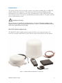
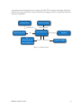
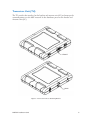
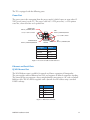
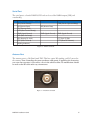
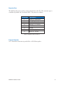
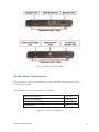
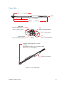
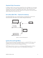
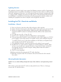
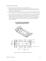
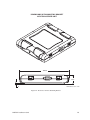
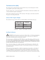
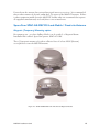
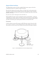
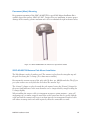
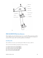
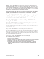
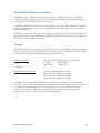
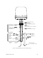
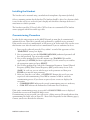
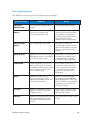
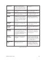
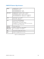
Introduction . . . . . . . . . . . . . . . . . . . . . . . . . . . . . . . . . . . . . . . . . . . . . . . . . . . . . . . . . . . . . . . . . . . .
Transceiver Unit (TU) . . . . . . . . . . . . . . . . . . . . . . . . . . . . . . . . . . . . . . . . . . . . . . . . . . . . . . . . . . .
Power Port . . . . . . . . . . . . . . . . . . . . . . . . . . . . . . . . . . . . . . . . . . . . . . . . . . . . . . . . . . . . . . . . . .
Ethernet and Serial Ports . . . . . . . . . . . . . . . . . . . . . . . . . . . . . . . . . . . . . . . . . . . . . . . . . . . . . .
RJ 45 Ethernet Port . . . . . . . . . . . . . . . . . . . . . . . . . . . . . . . . . . . . . . . . . . . . . . . . . . . . . . . . . . .
Serial Port . . . . . . . . . . . . . . . . . . . . . . . . . . . . . . . . . . . . . . . . . . . . . . . . . . . . . . . . . . . . . . . . . . .
Antenna Port . . . . . . . . . . . . . . . . . . . . . . . . . . . . . . . . . . . . . . . . . . . . . . . . . . . . . . . . . . . . . . . . .
Handset Port . . . . . . . . . . . . . . . . . . . . . . . . . . . . . . . . . . . . . . . . . . . . . . . . . . . . . . . . . . . . . . . . .
External Speaker . . . . . . . . . . . . . . . . . . . . . . . . . . . . . . . . . . . . . . . . . . . . . . . . . . . . . . . . . . . . . .
System Power Requirements . . . . . . . . . . . . . . . . . . . . . . . . . . . . . . . . . . . . . . . . . . . . . . . . . . . . .
Standard Cable Connections . . . . . . . . . . . . . . . . . . . . . . . . . . . . . . . . . . . . . . . . . . . . . . . . . . . . .
Horn Alert (Blue Wire - Optional Installation) . . . . . . . . . . . . . . . . . . . . . . . . . . . . . . . . . . . .
Ignition Sense (Orange Wire) . . . . . . . . . . . . . . . . . . . . . . . . . . . . . . . . . . . . . . . . . . . . . . . . . . . .
Basic Installation Procedure . . . . . . . . . . . . . . . . . . . . . . . . . . . . . . . . . . . . . . . . . . . . . . . . . . . . . .
Fixed-site Installation . . . . . . . . . . . . . . . . . . . . . . . . . . . . . . . . . . . . . . . . . . . . . . . . . . . . . . . . . . . .
Choosing a Location . . . . . . . . . . . . . . . . . . . . . . . . . . . . . . . . . . . . . . . . . . . . . . . . . . . . . . . . . .
Lightning Arrestors . . . . . . . . . . . . . . . . . . . . . . . . . . . . . . . . . . . . . . . . . . . . . . . . . . . . . . . . . . .
Installing the TU – Fixed-site and Vehicle . . . . . . . . . . . . . . . . . . . . . . . . . . . . . . . . . . . . . . . . . .
Installation – General . . . . . . . . . . . . . . . . . . . . . . . . . . . . . . . . . . . . . . . . . . . . . . . . . . . . . . . . .
Mounting Bracket Information . . . . . . . . . . . . . . . . . . . . . . . . . . . . . . . . . . . . . . . . . . . . . . . .
The Antenna Unit (AU) . . . . . . . . . . . . . . . . . . . . . . . . . . . . . . . . . . . . . . . . . . . . . . . . . . . . . . . . . .
Antenna Cable Lengths and Types . . . . . . . . . . . . . . . . . . . . . . . . . . . . . . . . . . . . . . . . . . . . .
Installing the Antenna . . . . . . . . . . . . . . . . . . . . . . . . . . . . . . . . . . . . . . . . . . . . . . . . . . . . . . . . .
SpaceCom SPAC-AS-MSV220 Land-Mobile / Fixed-site Antenna . . . . . . . . . . . . . . . . . . . .
Magnetic (Temporary) Mounting option . . . . . . . . . . . . . . . . . . . . . . . . . . . . . . . . . . . . . . . .
Permanent (Mast) Mounting . . . . . . . . . . . . . . . . . . . . . . . . . . . . . . . . . . . . . . . . . . . . . . . . . . .
SPAC-AS-MSV320 Maritime Antenna . . . . . . . . . . . . . . . . . . . . . . . . . . . . . . . . . . . . . . . . . . . . .
Pole Mount Kit . . . . . . . . . . . . . . . . . . . . . . . . . . . . . . . . . . . . . . . . . . . . . . . . . . . . . . . . . . . . . . .
Pole Mount Kit Component Description . . . . . . . . . . . . . . . . . . . . . . . . . . . . . . . . . . . . . . .
SPAC-AS-MSV320 Antenna Installation . . . . . . . . . . . . . . . . . . . . . . . . . . . . . . . . . . . . . . . . .
Vibration . . . . . . . . . . . . . . . . . . . . . . . . . . . . . . . . . . . . . . . . . . . . . . . . . . . . . . . . . . . . . . . . . . . . .
Installing the Handset . . . . . . . . . . . . . . . . . . . . . . . . . . . . . . . . . . . . . . . . . . . . . . . . . . . . . . . . . . .
Commissioning Procedure . . . . . . . . . . . . . . . . . . . . . . . . . . . . . . . . . . . . . . . . . . . . . . . . . . . . . . .
Troubleshooting the Installation . . . . . . . . . . . . . . . . . . . . . . . . . . . . . . . . . . . . . . . . . . . . . . . . . .
Steps to Basic Troubleshooting . . . . . . . . . . . . . . . . . . . . . . . . . . . . . . . . . . . . . . . . . . . . . . . .
Troubleshooting Some Typically Encountered Problems: . . . . . . . . . . . . . . . . . . . . . . . . .
MSAT-G2 Technical Specifications . . . . . . . . . . . . . . . . . . . . . . . . . . . . . . . . . . . . . . . . . . . . . . . . .
MSAT-G2 Installation Guide
1
3
4
4
4
5
5
6
6
7
9
9
9
10
10
10
11
11
11
11
14
14
14
15
16
17
18
18
19
21
21
23
23
26
26
27
28
Introduction
The purpose of this guide is to provide assistance to personnel installing the new MSAT-G2
mobile satellite radio equipment. The guide starts off by providing installation-specific
information on each component of the radio. Installation tips are then offered for fixed-site
and vehicular scenarios. A section on commissioning instructions follows. The guide concludes
with a troubleshooting section.
Installation Warning
This product is to be installed by Authorized Service Personnel. Damages resulting in the
failure to conform to the instructions found herein, as well as standard installation practices,
will be the responsibility of the installer.
MSAT-G2 Mobile Satellite Radio
The MSAT-G2 mobile satellite radio is comprised of three core component parts: the
transceiver unit (the small black box), the antenna system (white domes) and the handset.
Figure 1 – MSAT-G2 Mobile Satellite Radio Components
MSAT-G2 Installation Guide
1
An optional external speaker may be connected to the TU for remote monitoring. Serial and
ethernet ports are provided for external interfacing, debugging, software upgrading and future
expansion capabilities.
Antenna Unit
Antenna Cable
External Interface
Serial
PC
Debug/Upgrade/
Future Expansion
External Speaker
External Speaker
Transceiver Unit
Ethernet
Handset Cable
Power Cable
Handset
12 power supply
Figure 2 – System Overview
MSAT-G2 Installation Guide
2
Transceiver Unit (TU)
The TU provides the interface for the handset and antenna unit (AU) and manages the
communications over the MSV network. It also distributes power to the handset and
Antenna Unit (AU).
FRONT
BACK
Figure 3 - Transceiver Unit w/o Mounting Bracket
MSAT-G2 Installation Guide
3
The TU is equipped with the following ports:
Power Port
The power port is the connection from the power supply (vehicle battery or some other 12
VDC power source) to the TU. The power cable has a +12V power line, a +12V ignition
sense line, a horn alert line and a ground line.
HORN ALERT
AWG 20, STRANDED, BLUE
GND
AWG 16, STRANDED, BLACK
0.25 A, 1-1/4 BY 1/4 FUSE
5 A, 1 1/4 BY 1/4 FUSE
IGNITION SENSE
AWG 20, STRANDED, ORANGE
VIEW A
Line Type
+12VDC
Ground
Ignition Sense
Horn Alert
12 V
AWG 16, STRANDED, RED
Colour
Red
Black
Orange
Blue
Figure 4 – Power Port Cable Colour Reference
Ethernet and Serial Ports
RJ 45 Ethernet Port
The RJ 45 Ethernet port is available for upgrade and future expansion of functionality.
The port supplies standard Ethernet line levels and supports all defined control line signaling.
The pinout of the port supports a direct straight-through connection to a PC with a standard
Ethernet cable. The PC shall be supplied with a dynamic local IP address using a standard
DHCP exchange.
Pin
1
2
3
6
RX+
RXTX+
TX-
Figure 5 – Ethernet Port Pinout
MSAT-G2 Installation Guide
4
Serial Port
The serial port is a female DB-9F RS 232 and can be used for NMEA output (GPS) and
crossbanding.
Pin
Data (currently not supported)
1
2
3
4
5
6
7
8
9
CD (Carrier Detect)
RD (Receive Data)
TD (Transmit Data)
DTR (Data Terminal Ready)
GND (Signal Ground)
DSR (Data Set Ready)
RTS( Request To Send)
CTS (Clear To Send)
RI (Ring Indicator)
GPS
Crossband
COR (Carrier Operated Relay)
RD (Receive Data)
GND (Signal Ground)
GND (Signal Ground)
PTT (Push To Talk)
CTT (Clear To Transmit)
Figure 6 – Serial Port Pinout
Antenna Port
The antenna port is a 50 Ohm female TNC. This line carries RF, signaling, and DC power for
the antenna. Note: Grounding the center conductor while power is applied to the transceiver
can cause the transceiver's fuse and/or a fuse in the vehicle to blow. No modifications should
be made to the RF cable under any circumstance
Figure 7 – Antenna Port Detail
MSAT-G2 Installation Guide
5
Handset Port
The RJ45 handset port is used to connect the handset to the TU. The connector type is
a modular 8 position and 8 conductor RJ45. The pinout is as follows
Pin Number
Signal Name
1
2
3
4
5
6
7
Audio TX + Microphone
Audio TX – Microphone
Data TX – TU Send
Data RX – TU Receive
+ 12 VDC
Ground
Audio RX + Speaker
8
Audio RX - Speaker
Figure 8: Handset Connector Pin-out
External Speaker
A 3.5 mm mono connection is provided for a 4W 8Ohm speaker.
MSAT-G2 Installation Guide
6
Figure 9 – Transceiver Unit Front & Back
System Power Requirements
There is only one power connection for the entire radio. This must be connected to a
12 VDC power supply.
Power requirements and consumption are as follows:
Voltage Input Minimum
11.5 V DC
Voltage Input Maximum
15.6 V DC
Total Current for AU,TU & Handset (Max.)
3A
Required Fuse
5A
Figure 10 – System Power Requirements
MSAT-G2 Installation Guide
7
Power Cable
10 + / - 0 . 5 INCHES
VIEW A
6 + / - 0 . 5 INCHES
20 FEET + / - 4 INCHES
HORN ALERT
AWG 20, STRANDED, BLUE
GND
AWG 16, STRANDED, BLACK
0.25 A, 1-1/4 BY 1/4 FUSE
5 A, 1 1/4 BY 1/4 FUSE
IGNITION SENSE
AWG 20, STRANDED, ORANGE
VIEW A
12 V
AWG 16, STRANDED, RED
HOUSING : MOLEX PART NO. 39-01-2045
TERMINAL:
MOLEX PART NO. 44476-3111 (FOR AWG IG WIRE)
AND 44476-1111 (FOR 20 WIRE)
IN LINE FUSE HOLDER
Figure 11 – Power Cable Details
MSAT-G2 Installation Guide
8
Standard Cable Connections
In addition to the DC power connection, optional horn alert and ignition sense connections
may be made. These are all done using the four wire power cable. In the case of a vehicle
installation, the power source is typically the vehicle battery. Cables should be routed
appropriately and cable ties and clamps should be used as required to ensure that vibration
and/or rubbing of the cables does not occur.
Horn Alert (Blue Wire - Optional Installation)
To install the Horn Alert, route and splice the blue wire (Horn Alert) as shown below.
Note that the Horn Alert option is not available in Dispatch Radio mode.
12 VDC or ground as
required by vehicle
To auto horn
+12 VDC
Note: 0.25
amp fuse
required
To TU Horn Alert
(GND) (BLUE Wire)
Figure 12 – Horn Alert Wiring Diagram
Ignition Sense (Orange Wire)
Route and connect the orange wire (Ignition Sense) to a switched 12 VDC source, such
as ignition switch or fuse block. Extended use of ignition sense in accessory position
(ACC) by the end user may lead to a discharged car battery.
NOTE: Ensure that the connection is a switched source-OFF when ignition is off or in
start and ON only when ignition switch is in ACCESSORIES or RUN position.
MSAT-G2 Installation Guide
9
Basic Installation Procedure
While the installation of the MSAT-G2 mobile satellite radio is straightforward, it is essential
that the installation be done correctly.
The basic installation procedure is as follows:
1. Decide where you are going to install the antenna, TU and handset.
2. Ensure that the TU is located inside the vehicle or a building and that it is attached
to something structurally sound. Loose mounts that vibrate will degrade performance.
3. Determine the cabling required for the installation of each component.
4. Perform the installation of the antenna, TU and handset.
5. Connect the antenna and the handset to the TU
6. Connect the power to the TU.
7. Power up and commission the radio
Fixed-site Installation
Choosing a Location
It is important to choose a location for the antenna that will have a clear line-of-site to
the satellite(s). Preferably, avoid all obstructions within three (3) meters of the antenna.
Installation during windy conditions may be dangerous. The owner and installer assume all
responsibility to ensure that the equipment is properly installed with adequate structural
stability of mounting surface to withstand all loads (wind, weight, ice, etc.) and is properly
sealed to avoid leaks.
DO NOT ATTEMPT TO INSTALL OR DISMANTLE THE EQUIPMENT NEAR
ANY TYPE OF POWER LINE.
Safety Rules:
1) Select your installation site with safety as well as performance in mind.
2) Plan your installation carefully before beginning. Perform as many tasks as possible
while on the ground.
3) If any part of the equipment (i.e. antenna assembly) comes into contact with a power
line, do not try to remove it yourself. Contact your local power company.
4) When installing an antenna assembly, do not use a metal ladder.
5) If the antenna assembly starts to drop, get away from it and let it fall.
6) Verify that the antenna is properly grounded.
MSAT-G2 Installation Guide
10
Lightning Arrestors
The applicable electrical code(s) may require that lightning arrestors capable of supporting Lband transmissions be installed on all cabling between the fixed-site antenna and the structure
which the equipment is housed in. It is also suggested that any structure containing the radio
be equipped with a lightning rod connected to the ground. The professional doing the fixedsite installation is responsible for determining all such requirements with the customer and
installing the equipment such that it complies with all applicable standards.
Installing the TU – Fixed-site and Vehicle
Installation – General
1) For ease of service, route the radio cables and power cables together.
2) Always disconnect the negative side of the vehicle battery prior to any electrical work.
3) Whenever routing cable through holes drilled in metal or through bulkheads, use
grommets and RTV sealant to weatherproof all holes drilled on the outside of the
vehicle.
4) Use cable ties every 30 – 45 cm (12-18”).
5) The TU can be mounted in either the horizontal or vertical position.
6) The main power line should be connected directly to the vehicle battery (or 12 VDC
power supply). If you must connect it to another circuit, ensure sufficient amperage
is available. In the case of a fixed-site installation, tie the Battery and Ignition Sense
wires together on the 12 VDC power source.
7) The ground line should be connected directly to the vehicle’s battery ground.
8) Install the TU in a protected but ventilated area (inside building or vehicle). Allow
at least a one (1) inch space around all surfaces, except for the surface attached to
the mounting bracket to provide adequate cooling. Ensure that the location is
accessible for servicing.
9) The TU is not waterproof.
10) Always provision the wiring into the TU with a drip loop.
11) With the exception of the TU to Antenna cable, do not route the cables outside
the vehicle.
Mounting Bracket Information
NOTE: Use care when drilling through the body of the vehicle to avoid puncturing critical
items.
The bracket is connected to the TU with two (2) provided screws. There is a 5mm gap
between the TU and the bracket.
MSAT-G2 Installation Guide
11
Instructions for the installer:
1. The mounting bracket should be used for mounting the TU.
2. Mount the mounting bracket onto a flat surface using at least four (4) screws (not
supplied). Use screws with diameter between 3 to 4.5 mm. Vibration resistant screws
or lock washers should be used.
3. Choose any suitable holes and slots on the base of the mounting bracket for mounting
the screws. If space is available on the mounting surface, the screws should be spaced
as far as possible towards the corners of the mounting bracket to provide good stability.
4. Place the TU on the mounting bracket so that the holes on the side flanges of the
mounting bracket are aligned with the threaded inserts on the TU. Use only the two
screws and spring washers provided to secure the TU to the mounting bracket. Not
using the supplied bracket screws could result in damage to the TU (especially if
screws are too long).
MOUNTING HOLE DIMENSIONS
BOUNTING BRACKET, MSV
Dimensions are in mm
Figure 13 - Transceiver Unit Mounting Bracket Dimensions
MSAT-G2 Installation Guide
12
DIMENSIONS WITH MOUNTING BRACKET
MSV TRANSCEIVER UNIT
ETH
I
SER
HA
ND
AL
PO
ERN
ET
RT
SET
176.83
33.6
HANDSET
SERIAL PORT
ETHERNET
5
Dimensions are in mm
Figure 14 - Transceiver Unit w/ Mounting Bracket
MSAT-G2 Installation Guide
13
The Antenna Unit (AU)
The antenna unit is composed of the antenna element array, necessary high power and low
noise amplifier systems and a tracking system.
Two AU versions exist: a 2-axis unit intended for land-mobile and fixed-site installations and
a 3-axis unit for the maritime environment.
Connection to both AUs is made by a TNC connector. The single co-axial cable carries RX,
TX, power and tracking information.
Antenna Cable Lengths and Types
The radio has been type approved for use with the following cable lengths and types:
Cable Length
Antenna to Radio
20 ft
60 ft
150 ft
Cable Type
RG223/U
LMR240 (Equiv.)
LMR600 (Equiv.)
Figure 15 – Antenna Cable Lengths and Types
Installing the Antenna
WARNING: Avoid exposure to microwave radiation. Keep a safe distance of minimum
one 1 meter (39 inches) to the side and above the antenna. Always power the MSAT-G2
down prior to disconnecting or connecting the antenna.
The antenna port is a 50 Ohm female TNC. This line carries RF, signaling, and DC power for
the antenna. Note: Grounding the center conductor while power is applied to the transceiver
can cause the transceiver's fuse and/or a fuse in the vehicle to blow. No modifications should
be made to the RF cable under any circumstance.
Keep a clear line-of-sight to the satellite. Preferably, avoid all obstructions within three (3)
meters of the antenna. Obstructions less than 15 cm (6 inches) in diameter can be ignored
beyond this distance.
If the antenna is being mounted on a vehicle it is important to ensure there is a clear line-ofsite to the satellite(s) in all directions. After the radio is commissioned and operational it is
recommended that the signal strength be checked while the vehicle is slowly driven in a 360º
circle. The signal strength should not vary significantly or be degraded in any particular direction.
MSAT-G2 Installation Guide
14
Do not locate the antenna close to interfering signal sources or receivers. It is recommended
that no other antennas be located within three (3) meters of the MSAT-G2 antenna. If there
is other equipment installed near the MSAT-G2 satellite radio it is recommended to operate
all equipment simultaneously and verify there is no co-interference.
SpaceCom SPAC-AS-MSV220 Land-Mobile / Fixed-site Antenna
Magnetic (Temporary) Mounting option
For temporary use – or where drilling of holes is to be avoided – a Magnetic Mount
Installation Kit is offered. SpaceCom part no: SPAC-AC-1016.
Three (3) magnetic mounts each with an adhesive force of at least 420 N (Newton)
are required to secure the MSV220 antenna.
Figure 16 – SPAC-AS-MSV220 2-axis Antenna W/ Magnetic Mounts
MSAT-G2 Installation Guide
15
Magnetic Mount Installation
The Magnet Mount consists of (3) three individual high intensity magnets with rubber
coating. Each magnet has a stainless steel M5 center bolt.
First attach the magnets to the antenna. There are (3) three “legs” on the antenna where
the magnets are placed. Note the position of the two nylon (plastic) washers just below
and above each “leg”, the stainless steel washer above the upper nylon washer and the M5
protective nut on top.
Now place the antenna with magnets on the roof of the car.
When installing the antenna cable, it’s important to protect against moisture – using self
amalgating tape, or similar, wrapped around the coaxial connector. Also be careful with the
cable run from the antenna and secure it at short intervals. An unsupported length of cable
will vibrate when driving and could negatively affect the connection over time.
Dismounting:
Grab the antenna near one of the magnets and lift. When one magnet is loose, the other
two are easy to “break off”. In some situations the force of the magnet may be too great
and it will be necessary to unscrew the antenna first and remove the magnets separately.
Hex domed nut
M5 washer
Rubber washer
Rubber washer
High “intensity” magnet
Figure 17 – SPAC-AS-MSV220 2-axis Antenna W/ Magnetic Mounts
MSAT-G2 Installation Guide
16
Permanent (Mast) Mounting
For permanent mounting of the SPAC-AS-MSV220, a special Pole Mount Installation Kit is
available. SpaceCom part no.: SPAC-AC-1017. Designed for easy installation, it ensures proper
drainage of the antenna, galvanic insulation and is able to withstand the rigid mechanical stress.
Figure 18 – SPAC-AS-MSV220 2-axis Antenna W/ Optional Pole Mount
SPAC-AS-MSV220 Antenna Pole Mount Installation
The Pole Mount is made of stainless steel. The antenna is placed on the triangular top and
the pole fixed using the U-clamps. (To a short mast or similar)
First mount the antenna on top of the pole with (3) three pcs. M6x50 mm bolts. The (6) six
pcs. nylon washers are used just below and above the antenna “legs”
The 44 mm U-clamps are placed around the pole mount, leaving the 50 mm U-clamps for
the mast. Small tolerances in the mast diameter can be compensated by simply bending the
U-clamps slightly.
When installing the antenna cable, it is important to protect against moisture – using self
amalgating tape, or similar, wrapped around the coaxial connector. Also be careful with the
cable run from the antenna and secure it at short intervals. An unsupported length of cable
will vibrate in strong winds and could negatively affect the connection over time.
MSAT-G2 Installation Guide
17
M6X50 screw
M6 washer
Rubber washer
Rubber washer
U-clamp ø44 mm
M8 washer
M8 self-locking nut
M6 self-locking nut
Clamp bracket
U-clamp ø50mm
Figure 19 – SPAC-AS-MSV220 2-axis Antenna W/ Optional Pole Mount
SPAC-AS-MSV320 Maritime Antenna
When installing a SpaceCom Maritime Antenna on a vessel the following important guidelines
must be followed in order to ensure that the antenna will operate trouble-free throughout its
service life. The warranty will be void if the guidelines are not followed.
Pole Mount Kit
The installation is based on a pole mounting kit AC-1005 and is shown in FIG. 21.
The kit consist of the following components: (subject to change)
1pcs. Mounting Pole, Part No. SPAC-M00424
1pcs. Rubber Gasket, Part No. SPAC-M00425
6pcs. Plastic Bushings, Part No. SPAC-M00227
6pcs. Washer, Part No. SPAC-M90-10062
6pcs. Screw, Part No. SPAC-M90-10102
MSAT-G2 Installation Guide
18
2pcs. Clamp, Part No. SPAC-M00428
2pcs. Clamp, Part No. SPAC-M00429
8pcs. Nuts M8, Part No. SPAC-M90-10105
2pcs. Flange, Part No. SPAC-M00430
1pcs. Plug for Mounting Pole, Part No. SPAC-M00233
1pcs. Screw M5*10, Part No. SPAC-M90-10104
These components are shipped in one separate box. The installer, upon receipt of a
box, is required to check the contents.
Figure 20 – SPAC-AS-MSV320 Maritime Antenna W/ Optional Pole Mount
Pole Mount Kit Component Description
Mounting Pole Part No. SPAC-M00424 is a piece of standard tubing with a mounting flange
welded onto it. The component is made from a stainless steel alloy that is easy to cut, machine
and weld. It is part of the ventilating system for the dome. The standard length is 400mm
and must not be shortened in maritime applications. Shorter versions for non-maritime
applications may be supplied on special request.
Rubber Gasket, Part No. SPAC-M00425 is used to ensure that water or dust does not enter
into the area around the centre hole in the bottom of the dome. The centre hole is part of
the ventilating system for the dome and MUST NOT BE BLOCKED. The gasket will also
protect the TNC-type connector from water and dust.
MSAT-G2 Installation Guide
19
Bushings, Part No. SPAC-M00227 are used to ensure NO electrical contact between the
mechanical parts of the antenna (in the dome) and the mounting pole. This isolation is not
required in vehicle installations but is required in maritime installations, where the antenna
and co-axial cable to the antenna must be isolated from ships structure in order to avoid any
circulating DC current that could cause uncontrolled corrosion.
Washers, Part No. SPAC-M90-10062 are used to protect the plastic bushings SPAC-M00227
when the screws SPAC-M90-10102 are tightened to the specified torque. The washers
MUST be used.
Screws, Part No. SPAC-M90-10102 are M6 (metric), 25mm long screws made from stainless
steel (A4) are used for fastening the antenna to the flange on the mounting pole so that the
installation will endure vibrations and heavy loads due to wind or surges from rough sea.
DO NOT CHANGE THE LENGTH OF THE SCREWS.
Clamps, Part No. SPAC-M00428 are used to fasten the flanges SPAC-M00430 to the
mounting pole, refer to FIG.21.
Clamps, Part No. SPAC-M00429 are used to fasten the mounting pole to any post with a
diameter between 35 and 50 mm, refer to FIG.21.
Nuts, Part No. SPAC-M90-10105 are M8 nuts used for the clamps, refer to FIG.21 Nuts are
to be tightened to 5Nm.
Flange, Part No. SPAC-M00430 are used for linking the clamp holding forces.
Plug, Part No. SPAC-M00233 is used for partly closing the bottom of the Mounting Pole so
that no surge of water will fill the tube or damage any part of the antenna. Any condensing
water within the antenna and/or tube will drop out by the plug. The plug will also prevent
the coaxial cable from vibrating in the tube.
Screw, M5*10, Part No. SPAC-M90-10104 is used to secure the plug.
The kit offers the following advantages:
•
•
•
•
Flexible and easy installation.
Provides ventilation of the antenna while ensuring compliance with its relevant IP class.
Protects the co-axial cable going to the antenna and its N-type connector.
Isolates the antenna from the structure on which it is installed, this is a must in
maritime installations where no DC current is allowed to flow through any part
of the ship.
MSAT-G2 Installation Guide
20
SPAC-AS-MSV320 Antenna Installation
Installation of the 3-axis antenna on the mast is done according to FIG 21. The diameter
of the post shall preferably be between 35 and 50 mm using the standard clamp supplied
in the kit. Note the TORQUES for bolts and nuts.
A small loop should be made on the co-axial cable near the plug SPAC M00233 in order to
be able to pull the cable about 15 cm up through the mounting pole, when the antenna is
installed or removed.
If a long (e.g. 3m) post is used on board a ship it is recommended that this is fastened to the
ship using standard clamps rather than welding. This will enable the post to be laid down in
case removal of the antenna is required.
Vibration
The antennas (2- and 3-axis versions) are designed to meet the following operating vibration
levels in any of three perpendicular directions measured at the mounting base of the radome
i.e. at the flange of the standard mounting pole described above:
Random Vibration
1.05 Grms with the following spectral density
5-20 Hz………….0.02G2/Hz
20-150 Hz……….-3dB/octave
And further,
Single Frequency Vibration
5-10 Hz with amplitude 2.54 mm
10-15 Hz with amplitude 0.76mm
15-25 Hz with amplitude 0.40mm
25-33 Hz with amplitude 0.23mm
Vibration levels in a typical installation are usually much less than the above mentioned
values. It is, however, the responsibility of the installer to verify that the cited levels are not
exceeded in any mode of operation of the vehicle/vessel. In case of abnormal vibration,
typically at a resonance frequency, measures much be taken in order to displace the
resonance frequency or to dampen the vibration amplitude.
MSAT-G2 Installation Guide
21
Coax cable With TNC type
Connector
Rubber gasket
Part No.: SPAC-M00425 (1 ONLY).
Plastic bushing
Part No.: SPAC-M00227 (6 ONLY).
Washer
Part No.: SPAC- M90-10062 (6 ONLY).
Screw
Part No.: SPAC-M90-10102 (6 ONLY).
To be tightened to 4Nm
in two rounds
Mounting pole
Part No.: SPAC- M00421 (1 ONLY).
42.5
400
Nut M8 (8 ONLY)
To be tightened
to 10-1Nm
U-Clamp
SPAC-M00429
(2ONLY).
U-Clamp
SPAC-M00428
(2 ONLY).
Post on vessel
Flange
SPAC-M00430
(2 ONLY).
Screw M5x10
(1 ONLY)
Plug for mounting pole
Part No.: SPAC- MO0233 (1 0NLY)
35-50MM
Figure 21 – SPAC-AS-MSV320 3-axis Antenna Installation Details
MSAT-G2 Installation Guide
22
Installing the Handset
The handset can be mounted using a standard-sized microphone clip mount (included).
Select a mounting position for the handset. The handset should be placed in a location which
is easy for the user to see and reach (arm’s length) and which does not impede the user’s
movements or vehicle operation.
The handset is rated for 25 feet of cable. CAT5 or better is recommended. The handset
comes equipped with 6 foot coiled type cable.
Commissioning Procedure
In order for the unit to operate on the MSAT Network, it must first be commissioned –
authorized for use. This task is generally only performed by qualified service personnel.
If the unit has never been commissioned, it will power up in dealer mode. You can also access
this function even after the unit has been commissioned if you are authorized to do so.
1. Power up the radio and press the 5 key within 1 second of the appearance of the
“SEARCHING” message on display.
2. You are prompted to enter the DEALER PASSWORD (authorized personnel will
have this password). Type it in and press OK.
3. You are then prompted to select the antenna type: TRACKING (for mobile
applications) or OTHER (for future applications). Use the arrow keys to scroll to
the appropriate option and press SELECT.
4. You are then prompted for each of the Commission Parameters: Control Channel
Frequency (CFC), Pilot Channel Frequency (PFC), and Security Access Code
(SASK). In each case, you are asked to type in the parameter and then press
STORE to go onto the next parameter.
5. After you enter the set of values, a CONTINUE? Prompt asks you if you want
to proceed with commissioning. Press YES to continue or NO to cancel the
commissioning process. If you choose to proceed, two screens are displayed in
succession:
• COMMISSIONING indicates the general commissioning process is underway
• COM: PVT indicates the Performance Verification Test is underway.
If the entire commissioning process is successful a COM: SUCCESS screen is displayed.
Control then reverts to the initial Idle Mode screen.
If commissioning is not successful, you will receive a failure message (Network indicates that
commissioning has failed, refer to figure 22 – Error Code Diagnostics on the following pages).
Contact your Service Provider for assistance.
MSAT-G2 Installation Guide
23
Error Code Diagnostics
The following error messages may be displayed on the handset.
Error Condition
Definition
Action
FAILED TO
COMMISSION
The radio has been shutdown by the
network.
Contact MSV Customer Support.
COM: NO RESP RETRY?
Signifies that the network did not
respond to the commissioning
procedure initiated by the user.
Ensure that you have a clear view
of the southern sky and select YES
to re-initiate the commissioning
procedure. Contact MSV Customer
Support if the radio fails to
commission after several attempts
COM: FAILURE RETRY?
The commissioning process failed.
Select YES to re-initiate the
commissioning procedure. Contact
MSV Customer Support if the radio
fails to commission after several
attempts.
INVALID SASK
Signifies the user has entered an invalid
SASK while in the process of initiating
the commissioning procedure.
Check that you correctly entered
the SASK. If the problem persists,
contact MSV Customer Support
to obtain the proper SASK value.
SEARCHING…
If signal strength bars are seen, the
radio is in the process of connecting
to the MSAT network. If signal strength
bars are not seen, the radio cannot
receive a satellite signal.
If the condition persists, check
the radio has a clear view of the
southern sky and that the antenna
is connected and is functioning
(e.g. can hear the servo motor in
the antenna).
WAIT…
Signifies that the radio has not
received a response to the PTT
request from the MSAT network and
is attempting several retries.
Continue to press the PTT key.
If the call is successful, USER ON
will be displayed. In the event a call
fails, a PTT FAIL message will appear
requiring the user to release the
PTT key and try again.
PTT FAIL
Signifies the radio failed to receive a
response to the PTT request from
the MSAT network.
Release the PTT key and try again.
If this message continues, contact
MSV Customer Support.
PRESSPT
Signifies the PTT key was been pressed
then released just before the radio
received the confirmation from the
network.
Press and hold the PTT key in order
to talk.
MSAT-G2 Installation Guide
24
INVALID DN
Signifies the user has entered a
Directory Number (DN) that is not
a member of the private mode talk
group currently active on the radio.
Ensure a valid DN is entered in tag
position 00.
NO TG
No talk groups have been downloaded
to the radio.
If this condition persists, contact
MSV Customer Support.
BLOCKED
Signifies that the radio's antenna signal
to the satellite is blocked.
Ensure that the antenna has a clear
line-of-sight to the satellite.
X-OVER
FAILURE
Signifies that the user has initiated a
manual beam cross-over to a beam
that is not accessible. Following the
appearance of the failure message the
user will be returned to the beam
options list.
Ensure that the appropriate adjacent
satellite beam is chosen when
initiating a manual beam cross-over.
RF POWER
FAILURE
The radio detected a problem with its
RF transmissions and disabled that
transmitter.
Power cycle the radio. If this
condition persists, contact MSV
Customer Support.
ANTENNA
FAILURE
This indicates the radio has detected a
fault in the antenna and shut it down.
Power cycle the radio. If this problem
persists, contact MSV Customer
Support
WARNING!
OVERHEAT
Signifies that the radio is overheating.
This message will appear at 10 second
intervals until the temperature is
reduced. If the temperature continues
to increase then the radio will
shutdown.
Move the radio to a cooler place.
If the radio powers off, allow it to
cool down before re-initiating the
power-up sequence.
INVALID
PASSWORD
Signifies the user has entered the
wrong Dealer or SYSTEM Menu
password.
Enter the correct password. If the
password is unknown, contact MSV
Customer Support with the radio's
ESN. Customer Support can provide
a new SYSTEM password.
WRONG LOCK
CODE
Signifies the user has entered the
wrong Handset Lock code.
If you cannot remember the lock
code (default is 0000), enter the
SYSTEM password (default 1234)
when prompted to enter the code.
Figure 22 – Error Codes
MSAT-G2 Installation Guide
25
Troubleshooting the Installation
Steps to Basic Troubleshooting
When troubleshooting, always record as much information as possible at all times. Start
by asking the person who encountered the problem to describe the problem, the events
leading up to the problem and any troubleshooting work that may have been done already.
This information will be valuable when discussing the problem with others and will help
to debug similar problems in the future.
1) Characterize the problem.
Equipment performance:
Did the unit power up successfully?
What is shown on the handset display?
Were any error codes displayed?
Are you able to establish communications with another user?
What is the received communications quality like?
What does the transmitted communications quality sound like to other users?
Environmental conditions:
Record information about the location and the line-of-sight to the satellite:
Are there any blockages?
What are/were the weather conditions when the problem is/was encountered?
Is there any pattern as to when the problems occur (i.e. always when it rains, always
at 9 a.m., in the summertime but not the wintertime etc.)
How long has the problem existed?
When did it first show up?
Is it intermittent; or is it always present?
2) Eliminate operator error
Is the user familiar with the operation of the equipment?
Have they used it successfully in the past?
What was happening prior to the problem?
3) Is the problem really with the equipment?
4) Check the installation
What is the integrity of the installation?
Are the cable connections secure?
Are the cables damaged in any way?
Is the antenna system damaged?
Is the TU damaged?
Has any electrical or construction work been done near the TU, antenna or handset?
Is the power supply working properly?
MSAT-G2 Installation Guide
26
5) Troubleshoot by component
Does the problem sound TU-related, antenna-related, handset-related or external
equipment-related? Swap out a suspect component into a known working system
(i.e. if the TU is suspect, try it out with a known working antenna and handset).
It is highly recommended that a complete working satellite radio (TU, Handset,
and AU) be part of any troubleshooting kit.
Troubleshooting Some Typically Encountered Problems:
1) MT will not power up.
Start by checking that the power supply is working properly.
Check the power level supplied by the cable going into the TU.
Check that the power cable is securely connected to the TU.
2) Commissioning Fails
Is there sufficiently high enough signal strength?
Check the antenna for line-of-sight.
Check that the correct SASK, PFC & CFC are entered.
Check the TU ESN – is this the correct TU?
Check that the account is active and that the unit is in ready to commission status.
3) Signal Strength low/intermittent/none
Check the antenna cable connection both at the TU and antenna.
Check that the cable is not damaged in any way (pinched, cut etc.).
MSAT-G2 Installation Guide
27
MSAT-G2 Technical Specifications
Weight
HUGHES 2100 TU = 0.8 lbs
DT-200 Handset = 0.6 lbs
SPAC-AS-MSV220 Antenna = 4.6 lbs
SPAC-AS-MSV320 Antenna = 10.3 lbs
Dimensions
HUGHES 2100 TU = (W) 6.5” x (H) 1.1” x (D) 5.6”
DT-200 Handset = (W) 2.9” x (H) 1.4” x (D) 6.8”
SPAC-AS-MSV220 Antenna = (Diameter) 9.8” x (Height) 3.9”
SPAC-AS-MSV320 Antenna = (Diameter) 11” x (Height) 11”
Power
Input voltage: 11.5 to 15.6 VDC
Input current: 3 Amps max.
Fuses
Power cable assembly 3004028-0001
Battery (red wire): 5 Amp / 250 Volt
Horn Alert (blue wire): 0.25 Amp / 250 Volt
CAUTION: For continued protection against risk of fire, replace
only with same type and rating of fuse
Humidity
98% at 100.4°F (38°C)
Operating
Temperature
Antenna = -22°F(-30°C) to +109°F(+43°C)
TU = -22°F(-30°C) to +131°F(+55°C)
Dust
In Accordance with SAE J1455 section 4.7
Rain
Antenna = Precipitation rate of 2” /hour
Figure 23 – Technical Specifications
MSAT-G2 Installation Guide
28
Mobile Satellite Ventures
Customer Service
1-800-216-6728
[email protected]
Copyright © 2005 MSV
All rights reserved. This publication and its contents are proprietary
to Mobile Satellite Ventures, LP. No part of this publication may
be reproduced in any form or by any means without the written
permission of Mobile Satellite Ventures, LP, 10802 Parkridge
Boulevard, Reston, VA 20191-4334
Mobile Satellite Ventures, LP, has made every effort to ensure the
correctness and completeness of the material in this document.
Mobile Satellite Ventures, LP, shall not be liable for errors contained
herein. The information in this document is subject to change
without notice. Mobile Satellite Ventures, LP, makes no warranty
of any kind with regard to this material, including, but not limited
to, the implied warranties of merchantability and fitness for a
particular purpose.
Trademarks
All trademarks, marks, names, or product names referenced in this
publication are the property of their respective owners, and Mobile
Satellite Ventures, LP, neither endorses nor otherwise sponsors any
such products or services referred to herein.
MSV is a trademark of Mobile Satellite Ventures, LP.
MSAT-G2 Installation Guide
29